WO2011108747A1 - 中間画像生成方法、中間画像ファイル、中間画像生成装置、立体画像生成方法、立体画像生成装置、裸眼立体画像表示装置、立体画像生成システム - Google Patents
中間画像生成方法、中間画像ファイル、中間画像生成装置、立体画像生成方法、立体画像生成装置、裸眼立体画像表示装置、立体画像生成システム Download PDFInfo
- Publication number
- WO2011108747A1 WO2011108747A1 PCT/JP2011/055278 JP2011055278W WO2011108747A1 WO 2011108747 A1 WO2011108747 A1 WO 2011108747A1 JP 2011055278 W JP2011055278 W JP 2011055278W WO 2011108747 A1 WO2011108747 A1 WO 2011108747A1
- Authority
- WO
- WIPO (PCT)
- Prior art keywords
- rgb
- image
- staircase
- viewpoints
- pixel unit
- Prior art date
- Legal status (The legal status is an assumption and is not a legal conclusion. Google has not performed a legal analysis and makes no representation as to the accuracy of the status listed.)
- Ceased
Links
Images


















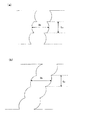


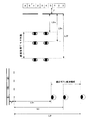

Classifications
-
- H—ELECTRICITY
- H04—ELECTRIC COMMUNICATION TECHNIQUE
- H04N—PICTORIAL COMMUNICATION, e.g. TELEVISION
- H04N13/00—Stereoscopic video systems; Multi-view video systems; Details thereof
- H04N13/30—Image reproducers
- H04N13/349—Multi-view displays for displaying three or more geometrical viewpoints without viewer tracking
- H04N13/351—Multi-view displays for displaying three or more geometrical viewpoints without viewer tracking for displaying simultaneously
-
- H—ELECTRICITY
- H04—ELECTRIC COMMUNICATION TECHNIQUE
- H04N—PICTORIAL COMMUNICATION, e.g. TELEVISION
- H04N13/00—Stereoscopic video systems; Multi-view video systems; Details thereof
- H04N13/10—Processing, recording or transmission of stereoscopic or multi-view image signals
- H04N13/106—Processing image signals
- H04N13/111—Transformation of image signals corresponding to virtual viewpoints, e.g. spatial image interpolation
-
- H—ELECTRICITY
- H04—ELECTRIC COMMUNICATION TECHNIQUE
- H04N—PICTORIAL COMMUNICATION, e.g. TELEVISION
- H04N13/00—Stereoscopic video systems; Multi-view video systems; Details thereof
- H04N13/10—Processing, recording or transmission of stereoscopic or multi-view image signals
- H04N13/106—Processing image signals
- H04N13/15—Processing image signals for colour aspects of image signals
-
- H—ELECTRICITY
- H04—ELECTRIC COMMUNICATION TECHNIQUE
- H04N—PICTORIAL COMMUNICATION, e.g. TELEVISION
- H04N13/00—Stereoscopic video systems; Multi-view video systems; Details thereof
- H04N13/30—Image reproducers
- H04N13/302—Image reproducers for viewing without the aid of special glasses, i.e. using autostereoscopic displays
- H04N13/31—Image reproducers for viewing without the aid of special glasses, i.e. using autostereoscopic displays using parallax barriers
-
- H—ELECTRICITY
- H04—ELECTRIC COMMUNICATION TECHNIQUE
- H04N—PICTORIAL COMMUNICATION, e.g. TELEVISION
- H04N13/00—Stereoscopic video systems; Multi-view video systems; Details thereof
- H04N13/30—Image reproducers
- H04N13/302—Image reproducers for viewing without the aid of special glasses, i.e. using autostereoscopic displays
- H04N13/317—Image reproducers for viewing without the aid of special glasses, i.e. using autostereoscopic displays using slanted parallax optics
-
- H—ELECTRICITY
- H04—ELECTRIC COMMUNICATION TECHNIQUE
- H04N—PICTORIAL COMMUNICATION, e.g. TELEVISION
- H04N13/00—Stereoscopic video systems; Multi-view video systems; Details thereof
- H04N13/30—Image reproducers
- H04N13/324—Colour aspects
-
- H—ELECTRICITY
- H04—ELECTRIC COMMUNICATION TECHNIQUE
- H04N—PICTORIAL COMMUNICATION, e.g. TELEVISION
- H04N13/00—Stereoscopic video systems; Multi-view video systems; Details thereof
- H04N13/10—Processing, recording or transmission of stereoscopic or multi-view image signals
- H04N13/106—Processing image signals
- H04N13/139—Format conversion, e.g. of frame-rate or size
Definitions
- the present invention relates to a method and apparatus for converting a plurality of viewpoint images taken from a plurality of viewpoints to generate an intermediate image and a stereoscopic image, a system for generating a stereoscopic image using them, and an apparatus for displaying the stereoscopic image And about.
- Patent Document 1 Conventionally, images taken from multiple viewpoints are arranged diagonally in pixel units or sub-pixel units for each viewpoint to form a display screen, and a barrier is placed on the front surface to give parallax to make stereoscopic images visible Technology is widely used (for example, Patent Document 1).
- Patent Document 2 discloses that the pixel arrangement of an image is converted into a pixel arrangement corresponding to a parallax barrier type stereoscopic image display device.
- This technique is disclosed in paragraph 0088 and FIG. Paragraph 0088 and FIG. 1 disclose a stereoscopic image display apparatus provided with an image composition circuit as a technical solution for converting the pixel arrangement of an image into a stereoscopic display in the apparatus.
- Non-Patent Document 1 discloses software for converting a pixel arrangement of an image for stereoscopic display to be executed on a personal computer.
- a large-scale stereoscopic image display system that is, a special and expensive graphic board capable of executing complex arithmetic processing for generating a stereoscopic image from a captured image at high speed is installed.
- a computer is an essential element.
- an image in which the images of the respective viewpoints are arranged in a tile shape often has a resolution and an aspect ratio that are different from the resolution of a stereoscopic image, that is, an autostereoscopic display.
- a stereoscopic image that is, an autostereoscopic display.
- the total problem is the same.
- the biggest problem is that it is not possible to provide images for each viewpoint for generating stereoscopic images in a standard format for storing and transmitting video on Blu-ray or STB. is there.
- the present invention generates a high-speed special computer or the like by generating in advance an intermediate image having the same resolution as that of the stereoscopic image that is the final output image and collecting pixels for each viewpoint. It is possible to generate a stereoscopic image by simply changing the arrangement of pixels without using it, and using an intermediate image in which the images of each viewpoint are arranged in a tile shape, standard image output devices such as Blu-ray and STB and image distribution It is a technical object to realize a stereoscopic image generation system that generates a stereoscopic image from the intermediate image output or transmitted by a server in a standard format by a simple and inexpensive stereoscopic image generation apparatus (converter).
- an intermediate image generation method is to generate a stereoscopic image converted from a plurality of viewpoint images photographed and / or drawn from a plurality of viewpoints from one viewpoint to N viewpoints.
- An intermediate image generation method for generating a plurality of intermediate images to be used in which RGB staircase-arranged pixel units in which sub-pixels are arranged in three rows in a diagonal direction in contact with corners from the one viewpoint to the N viewpoint in the horizontal direction
- RGB staircase-arranged pixel blocks arranged contiguously, the R value, G value, and B value of each of the sub-pixels constituting the RGB staircase-arranged pixel unit.
- An RGB parallel arrangement pixel unit in which subpixels constituting the RGB staircase arrangement pixel unit are arranged in the order of R, G, and B in the horizontal direction.
- the RGB parallel arrangement of the plurality of intermediate images and the RGB staircase arrangement pixel unit of the stereoscopic image by generating the intermediate image for each of the plurality of viewpoints by arranging according to an arrangement rule for arranging the viewpoints collectively
- the total number of pixel units or the total number of sub-pixels constituting each pixel unit is the same.
- the RGB staircase-arranged pixel unit has one column of subpixels for each row, and is composed of three subpixels having an R value, a G value, and a B value. It is desirable that the three subpixels are arranged in three rows in the order of R, G, and B in one row.
- the sub-pixel is a vertically long rectangle with a ratio of 1: 3
- the sub-pixels in which the three sub-pixels that are most appropriately stereoscopically viewable are arranged in 3 rows and 1 column in contact with the corner in an oblique direction.
- a plurality of intermediate images that can be converted into a stereoscopic image having an arrangement of pixels can be generated.
- the intermediate image generation method wherein the RGB staircase-arranged pixel unit has two columns of subpixels for each row, and each column of the two columns has an R value, a G value, and a B value.
- the RGB parallel arrangement pixel unit includes three subpixels arranged in three rows in one row and three rows in the first column of the RGB staircase arrangement pixel unit. Three sub-pixels arranged in three rows in the order of B and arranged in three rows in the second column of the RGB staircase-arranged pixel unit are arranged in three rows in the order of R, G, B. It is desirable that they are arranged side by side.
- the RGB staircase-arranged pixel unit has three columns of subpixels for each row, and each column of the three columns has an R value, a G value, and a B value.
- the RGB parallel arrangement pixel unit includes three subpixels arranged in three rows in one row and three rows in the first column of the RGB staircase arrangement pixel unit. Three sub-pixels arranged in three rows in the second column of the RGB staircase-arranged pixel unit are arranged in the order of R, G, and B. Further, it is desirable that the three sub-pixels arranged in the third row of the RGB staircase-arranged pixel unit are arranged in the order of R, G, and B in further connection with the arrangement.
- the intermediate image generation method wherein the plurality of intermediate images are arranged in a plurality of tiles including first to third rows that are at least vertically divided into three as image frames.
- the resolution and aspect ratio of the intermediate image and the autostereoscopic display become the same, and it is standardized by standard image output devices such as Blu-ray and STB and image distribution servers. It is possible to provide a practical 3D image display system that can easily generate a 3D image from an intermediate image output or transmitted in a format by a 3D image generation device (converter) at a very low price. .
- the intermediate image generation method when the plurality of viewpoints are two viewpoints, 2/3 of the intermediate image of one viewpoint and the second row of tiles in the first row
- the first tile is connected to 1/3 of the intermediate image of 1 viewpoint
- the second tile is 1/3 of the intermediate image of 2 viewpoints
- the third row tile is 2 of the intermediate image of 2 viewpoints.
- the intermediate images of the three viewpoints, the intermediate images of the remaining viewpoints on the tiles arranged in the first to third rows connected to the intermediate images of the first to third viewpoints In the case of the viewpoint, the intermediate image of 1 to 3 viewpoints and the 1 to 3 viewpoints of the first tile in each row 4 to 6 viewpoints of the intermediate image connected to the intermediate image from the first row to the third row, and tiles arranged from the first row to the third row connected to the intermediate image of the 4 to 6 viewpoints
- a part or all of the intermediate images may be arranged on the tiles in each row in the same manner from one viewpoint. desirable.
- the intermediate image generation method wherein, instead of the arrangement rule, the positions of subpixels constituting the RGB staircase arrangement pixel unit of the stereoscopic image and the RGB of the intermediate image for each of the plurality of viewpoints Referring to a previously created intermediate image generation table that associates the positions of subpixels constituting the parallel arrangement pixel unit, the subpixels constituting the RGB staircase arrangement pixel unit are arranged, and the RGB parallel arrangement pixel unit is It is desirable to generate.
- each of the plurality of viewpoint images and the stereoscopic image have the same aspect ratio, from the one viewpoint to the N viewpoints constituting the RGB staircase arranged pixel block.
- the RGB staircase-arranged pixel units of the RGB staircase-arranged pixel unit the R value, G value, and B value of each of the sub-pixels constituting the RGB staircase-arranged pixel unit at a predetermined reference viewpoint constitute the RGB staircase-arranged pixel unit.
- the RGB staircase arrangement for viewpoints other than the reference viewpoint obtained by interpolating from the RGB values of the subpixels constituting the pixel unit arranged in the vicinity of the corresponding position in the viewpoint image of the reference viewpoint corresponding to the arrangement position of the subpixel.
- the R, G, and B values of each of the sub-pixels that constitute the pixel unit constitute the RGB staircase arrangement pixel unit of the reference viewpoint. Obtaining by interpolating from the RGB values of the viewpoint image of the sub-pixels constituting at least one pixel unit arranged in the vicinity of the corresponding position in the viewpoint image of the viewpoint other than the reference viewpoint corresponding to the arrangement position of the subpixel. desirable.
- An intermediate image generation apparatus is an intermediate image generation apparatus for generating a plurality of intermediate images by the method according to claim 1, and the intermediate image generation apparatus includes at least a central processing unit and a storage device.
- the central processing unit arranges RGB staircase-arranged pixel units in which sub-pixels are arranged in three rows in a diagonal direction in contact with corners in a diagonal direction, and are connected in a horizontal direction from the 1 viewpoint to the N viewpoint.
- the R step, G value, and B value of each of the sub-pixels constituting the RGB staircase arranged pixel unit are converted into the RGB staircase arranged pixel unit.
- An RGB parallel arrangement pixel unit obtained by interpolating the RGB values of the subpixels formed and arranging the subpixels constituting the RGB staircase arrangement pixel unit in the horizontal direction in the order of R, G, and B is arranged for each of the plurality of viewpoints.
- the RGB staircase-arranged pixel units of the stereoscopic image and the RGB parallel-arranged pixel units having the same total number or the total number of sub-pixels constituting each of the RGB staircase-arranged pixel units An intermediate image for each of a plurality of viewpoints is generated.
- a stereoscopic image generation method is a method of generating a stereoscopic image from a plurality of intermediate images generated by the method according to claim 1, wherein the arrangement rule is determined from the intermediate images for each of the plurality of viewpoints.
- sub-pixels constituting the RGB parallel arrangement pixel unit are arranged as the RGB staircase arrangement pixel unit to generate the stereoscopic image.
- the position of subpixels constituting the RGB parallel arrangement pixel unit of the intermediate image for each of the plurality of viewpoints, and the stereo image are arranged as the RGB staircase arrangement pixel unit with reference to a previously created stereoscopic image generation table that associates the positions of the sub-pixels constituting the RGB staircase arrangement pixel unit. It is desirable.
- An intermediate image generation apparatus is a stereoscopic image generation apparatus for generating a stereoscopic image from a plurality of intermediate images by the method according to claim 11, wherein the stereoscopic image generation apparatus is at least a central processing unit.
- the central processing unit stores the intermediate images for each of the plurality of viewpoints in the storage device, and the RGB parallel arrangement according to the reverse order of the arrangement rules from the intermediate images for the plurality of viewpoints.
- Sub-pixels constituting a pixel unit are arranged as the RGB staircase-arranged pixel unit to generate the stereoscopic image.
- the stereoscopic image generation system includes at least a central processing unit, a storage device, a compression device, and a transmission device, and includes a plurality of viewpoint images captured and / or drawn from a plurality of viewpoints from one viewpoint to N viewpoints.
- a first information processing apparatus that generates a plurality of intermediate images used to generate a stereoscopic image to be converted, and at least a central processing unit, a storage device, a decompression device, and a receiving device,
- a stereoscopic image generation system including a second information processing device for generating an image, wherein the central processing unit of the first information processing device is arranged in three rows with sub-pixels contacting each other at a corner in an oblique direction
- the RGB staircase-arranged pixel unit is arranged by repeating RGB staircase-arranged pixel blocks in which the RGB staircase-arranged pixel units are arranged in a horizontal direction from the 1st viewpoint to the Nth viewpoint.
- the R value, the G value, and the B value of each of the sub-pixels constituting the RGB staircase-arranged pixel unit correspond to the arrangement positions of the sub-pixels constituting the RGB staircase-arranged pixel unit
- An RGB staircase-arranged pixel unit obtained by interpolating from RGB values of subpixels constituting at least one pixel unit arranged in the vicinity of the corresponding position in the plurality of viewpoint images stored in the storage device of the information processing apparatus
- An RGB parallel arrangement pixel unit in which sub-pixels constituting the image are arranged in the order of R, G, and B in the horizontal direction is arranged according to an arrangement rule for collectively arranging the plurality of viewpoints, and the RGB staircase arrangement of the stereoscopic image
- the plurality of views configured by the pixel unit and the RGB parallel arrangement pixel units in which the total number or the number of pixels constituting each unit is the same.
- An intermediate image for each of the plurality of viewpoints, the intermediate image for each of the plurality of viewpoints is compressed by the compression device, transmitted to the second information processing device by the transmission device, and the central processing of the second information processing device
- the apparatus receives the intermediate images for each of the plurality of viewpoints transmitted from the first information processing apparatus by the receiving device, decompresses the plurality of intermediate images by the decompressing device, and decompresses the intermediate images by the decompressing device.
- the stereoscopic image is generated by arranging the sub-pixels constituting the RGB parallel arrangement pixel unit as the RGB staircase arrangement pixel unit in the reverse order of the arrangement rules from the intermediate images for each of the plurality of viewpoints.
- the present invention it is possible to generate a compressible intermediate image with the minimum necessary resolution so that the total number of pixels constituting the image for each viewpoint is the same as the number of pixels of the stereoscopic image, and to configure such an intermediate image.
- 3D images can be generated at high speed without using a special computer by only rearranging (mapping) the subpixels to be used, and images of each viewpoint are arranged in tiles according to the present invention.
- the resolution and aspect ratio of the intermediate image and the autostereoscopic display (stereoscopic image) become the same, and the intermediate image is output or transmitted in a standard format by a standard image output device such as Blu-ray or STB or an image distribution server.
- a standard image output device such as Blu-ray or STB or an image distribution server.
- FIG. 1 is a block diagram schematically showing a configuration of an intermediate image generation device, a configuration of a stereoscopic image generation device, and a configuration of an information processing device used in a stereoscopic image generation system according to the present invention.
- the intermediate image generation device 31 in FIG. 1A includes a central processing unit 33 and a storage device 35.
- the storage device 35 stores a plurality of viewpoint images taken and / or drawn from a plurality of viewpoints from one viewpoint to N viewpoints.
- the generation of the viewpoint image includes taking a picture of an object from different viewpoints using a plurality of cameras and drawing it using computer graphics.
- the central processing unit 33 performs a plurality of arithmetic processes from a plurality of viewpoint images stored in the storage device 35 to generate an intermediate image.
- 1 (b) includes a central processing unit 33 and a storage device 35.
- the central processing unit 35 stores the plurality of input intermediate images in the storage device 35 (frame buffer), converts the pixel arrangement, and generates a stereoscopic image.
- the stereoscopic image generation system in FIG. 1C includes a first information processing device 41 and a second information processing device 47.
- the first information processing device 41 includes a central processing device 33, a storage device 35, and a compression device.
- the second information processing device 47 includes a central processing device 33, a storage device 35, a decompression device 49, and a reception device 51.
- the compression device 43 performs irreversible compression of a plurality of intermediate images by a predetermined method.
- JPEG is used for still images
- MPEG-2, MPEG-4, etc. are used for moving images.
- the transmission device 45 transmits the plurality of intermediate images compressed by the compression device 43 to the second information processing device 47.
- As a transmission method in addition to wired transmission via a USB port, wireless transmission such as optical communication, BLUETOOTH (registered trademark), and wireless LAN can be considered.
- the receiving device 51 receives a plurality of intermediate images transmitted by the transmitting device 45.
- the decompressing device 49 decompresses a plurality of intermediate images compressed by the compressing device 43.
- FIG. 2A is a flowchart of information processing executed by the intermediate image generation device 31 in FIG.
- the central processing unit 33 provided in the intermediate image generating device 31 is operated by a user (shooting an object with a camera from a plurality of viewpoints from one viewpoint to N viewpoints, or one viewpoint).
- a plurality of viewpoint images input according to computer graphics drawing from a plurality of viewpoints from N to N viewpoints are stored in the storage device 35 provided in the intermediate image generation device 31 (step S201).
- control information means a scanning method such as NTSC or PAL, a transmission method such as interlace or progressive, the number of viewpoints, resolution, pixel arrangement method, and the like.
- the control information is input by a user operation using a keyboard, a mouse, or the like further provided in the intermediate image generating device 31. As a result, the format is determined.
- the central processing unit 33 If the control information is input as a result of the determination in step S202, the central processing unit 33 generates a stereoscopic image based on the control information (step S203).
- the stereoscopic image refers to an image having a stereoscopically visible subpixel arrangement that is finally presented to the user.
- the subpixel In the case of autostereoscopic vision using a parallax barrier or the like, the subpixel is displayed in a diagonal direction.
- the RGB staircase-arranged pixel units arranged in three rows in contact with each other are arranged repeatedly by arranging RGB staircase-arranged pixel blocks arranged in a horizontal direction from the first viewpoint to the Nth viewpoint to form a stereoscopic image. It is desirable.
- the generation of a stereoscopic image based on the control information means that, for example, when the resolution of a display scheduled to display a stereoscopic image is 1980 ⁇ 1080, a stereoscopic image having a resolution suitable for output, that is, 1980 ⁇ 1080. A stereoscopic image having a resolution of 1 is generated. Note that the generation of the stereoscopic image performed in step S203 will be described later.
- the central processing unit 33 generates a plurality of intermediate images from the generated stereoscopic image (step S204).
- the intermediate image is an image used to generate a stereoscopic image, and each of the plurality of intermediate images has the subpixels constituting the RGB staircase arranged pixel unit arranged in the order of R, G, and B in the horizontal direction.
- the RGB parallel arrangement pixel units are collectively arranged for each of a plurality of viewpoints.
- a stereoscopic image is generated or assumed in advance from a plurality of viewpoint images photographed or drawn from a plurality of viewpoints, and an intermediate image is generated based on the stereoscopic image.
- the generation of the intermediate image performed in step S204 will be described in detail below as in step S203.
- the central processing unit 33 stores the intermediate image generated in step S204 in the storage device 35 (step S205).
- step S205 When the intermediate image is stored in step S205, this process ends.
- the process may return to step S203 again.
- a stereoscopic image and an intermediate image are repeatedly generated based on the same control information (when viewpoint images are input to the intermediate image generation device one after another), it is not necessary to input control information every time. Improvement of usability can be expected.
- the intermediate image generating apparatus 31 in order to make the intermediate image generating apparatus 31 recognize that the three-dimensional image and the intermediate image are continuously generated, the mode is changed by a specific operation such as a keyboard, and the three-dimensional image and the intermediate image are repeatedly generated. You may associate with a process.
- step S204 the following processing may be performed assuming a stereoscopic image without actually generating a stereoscopic image.
- FIG. 2C is a flowchart of information processing executed by the stereoscopic image generation system of FIG.
- step S204 in FIG. 2 (a) is basically the same as the processing up to step S204 in FIG. 2 (a), and redundant description of the same components is omitted, and only different parts are described below.
- the first information processing device 41 and the second information processing device 47 include a compression device 43, a transmission device 45, a decompression device 49, and a reception device 51, respectively, in the intermediate image generation device 31 used in FIG. An information processing apparatus further provided.
- the central processing unit 33 of the first information processing apparatus 41 compresses the plurality of intermediate images generated in step S204 by the compression apparatus 43 (step S205).
- step S205 the plurality of intermediate images compressed in step S205 are stored in the storage device 35 (step S206).
- the central processing unit 33 transmits a plurality of intermediate images compressed and stored from the transmission device 45 to the second information processing device 47 (step S207).
- the central processing unit 33 of the second information processing device 47 receives the plurality of intermediate images transmitted from the first information processing device 41 in step S207 by the receiving device 51 (step S208).
- the central processing unit 33 decompresses the received plurality of intermediate images by the decompressing device 49 (step S209).
- the central processing unit 33 generates a stereoscopic image that is finally output to the user from the plurality of decompressed intermediate images (step S210).
- the stereoscopic image in step S210 and the stereoscopic image in step S203 are the same.
- the generation of the intermediate image performed in step S210 will be described in detail below as in steps S203 and S204.
- the generated intermediate image may be output to the stereoscopic image display device 65. Further, when the intermediate image is continuously transmitted from the first information processing apparatus 41, the processing from step S208 to step S210 may be continuously performed.
- a plurality of viewpoints generated by the first information processing apparatus 41 one after another by installing a plurality of cameras at any point and continuously performing shooting. It is possible to distribute an intermediate image in which each image is arranged in a tile shape around the world in an existing format to allow many users to view a stereoscopic image simultaneously and in real time.
- the first information processing apparatus 41 is equipped with an expensive graphic board, a high-speed CPU, or the like for generating a plurality of intermediate images in real time, and a plurality of second information processing used by the user.
- the device 47 is equipped with a relatively low-speed CPU, an unprecedented stereoscopic image viewing environment that takes advantage of the characteristics of a plurality of intermediate images that can generate a stereoscopic image only by changing the pixel arrangement is provided in an existing format. Can be realized. That is, the generation of a compressible intermediate image with the minimum required resolution that the total number of pixels constituting the image for each viewpoint is the same as the number of pixels of the stereoscopic image, and the subpixels constituting such an intermediate image.
- a stereoscopic image that can be stereoscopically viewed only by rearrangement (mapping) can be generated at high speed without using a special computer.
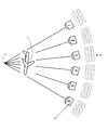
- FIG. 3 shows an example in which a certain object 1 is photographed by a camera 3 from a plurality of different viewpoints, and viewpoint images 5 for each viewpoint are generated. Since the gazing point 2 is shot from the six viewpoints using the camera 3, six viewpoint images 5 are obtained. Note that the resolution of the viewpoint image at this point is arbitrary.
- the cameras 3 may be arranged horizontally so that the optical axes of the respective cameras 3 are directed toward the gazing point 2.
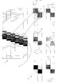
- FIG. 4 shows an example of generating a stereoscopic image 7 having a sub-pixel arrangement for finally outputting on the display from the plurality of viewpoint images 5 taken in FIG.
- the RGB value of the RGB staircase-arranged pixel unit 11 is obtained by interpolating from the RGB values of the sub-pixels constituting at least one or more pixel units arranged in the vicinity of the corresponding position.
- the central processing unit 33 described above first determines the sub-pixel arrangement of the stereoscopic image 7 according to the resolution of the display that performs the final output input in step S202 of FIG.
- the sub-pixel arrangement of the stereoscopic image for example, the one illustrated in FIG. 11 is used.
- the sub-pixels are vertically long rectangles with a ratio of 1: 3
- the three sub-pixels that are most suitable for stereoscopic viewing are arranged in 3 rows and 1 column in contact with the corners in an oblique direction.
- a stereoscopic image 7 having a subpixel arrangement is assumed.
- an RGB staircase-arranged pixel block corresponding to the number of viewpoints as shown in FIG.
- the RGB staircase-arranged pixel block refers to an RGB staircase-arranged pixel unit in which subpixels are arranged in three rows by contacting corners in an oblique direction and arranged in a horizontal direction from one viewpoint to N viewpoints.
- a group of pixels composed of 18 subpixels is defined as an RGB staircase arranged pixel block.
- the RGB staircase-arranged pixel blocks are repeatedly arranged to form the stereoscopic image 7, and the RGB values of the sub-pixels constituting the RGB staircase-arranged pixel unit are acquired.
- the acquisition of RGB values is desirably performed based on any RGB staircase-arranged pixel unit in the RGB staircase-arranged pixel block, and corresponds to the coordinate values on the stereoscopic image 7 of the subpixels constituting the RGB staircase-arranged pixel unit. Obtained from the RGB values of the sub-pixels arranged at the coordinate values on the viewpoint image.
- the coordinate value on the stereoscopic image 7 is U as the sub-pixel coordinate system and the vertical axis as V and the vertical axis as V.
- the subpixel arranged at the uppermost stage of the first viewpoint can be expressed as (U, V) as shown in the figure.
- the coordinate values on the viewpoint image have a horizontal axis of x and y of the vertical axis in the pixel coordinate system, and the coordinate values of the pixels on the viewpoint image of the first viewpoint as a reference in this embodiment are as shown in the figure ( x, y).
- a stereoscopic image and a plurality of viewpoint images have different numbers of subpixels, and since a subpixel coordinate system is used on a stereoscopic image and a pixel coordinate system is used on a viewpoint image, a predetermined conversion formula is is necessary.
- the total number of sub-pixels constituting the stereoscopic image in the horizontal direction is W
- the total number in the vertical direction is H
- the total number of pixels constituting the viewpoint image in the first viewpoint in the horizontal direction is a
- the total number in the vertical direction is b.
- the transformation from the sub-pixel coordinate system to the pixel coordinate system is
- RGB values can be obtained in units of individual sub-pixels, and a higher-definition stereoscopic image can be generated than when RGB values are obtained in units of pixels. Can do.
- the RGB values of other sub-pixels constituting the same RGB staircase arrangement pixel unit are similarly obtained by interpolating from the neighboring pixel units.
- interpolation methods There are various interpolation methods, and any interpolation method may be used as long as it is an appropriate interpolation method.
- the RGB values of the sub-pixels constituting the RGB staircase-arranged pixel unit other than the RGB staircase-arranged pixel unit of the first viewpoint as a reference are calculated.
- the RGB values are calculated from the pixels of other viewpoint images at the same position as the coordinate values on the viewpoint image corresponding to the coordinate values of the sub-pixels constituting the RGB staircase arranged pixel unit.
- the correspondence between the plurality of viewpoint images and the stereoscopic image is, for example, as illustrated in FIG.
- the RGB values of the sub-pixels constituting the stereoscopic image are obtained by interpolation calculation, and a stereoscopic image is generated or assumed.
- intermediate image generation step S204
- interpolation calculation for acquiring RGB values or interpolation calculation thereof is performed. It is necessary to rearrange the sub-pixels constituting the RGB staircase arrangement pixel unit of the obtained stereoscopic image to obtain RGB parallel arrangement pixel units of a plurality of intermediate images.
- step S204 the generation of the intermediate image performed in step S204 will be described in detail.
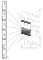
- FIG. 6 is a diagram illustrating an example of generating a plurality of intermediate images from a stereoscopic image.
- the RGB parallel arrangement pixel unit 17 in which the sub-pixels constituting the RGB staircase arrangement pixel unit 11 of the stereoscopic image generated in FIG. 4 are arranged in the horizontal direction in the order of R, G, and B is arranged in a plurality of viewpoints.
- Six intermediate images 15 are generated by arranging them together.
- the RGB parallel arrangement pixel unit 17 arranges the sub-pixels peeking from the slits arranged in a staircase shape or the holes arranged in a staircase shape as shown in the figure. This is performed for all the RGB staircase arranged pixel units 11. It should be noted that the generation of the plurality of intermediate images 15 from the stereoscopic image 7 is desirably performed using an intermediate image generation table.
- FIG. 7 is a diagram for explaining the intermediate image generation table.
- FIG. 7A shows which viewpoint image is displayed by the subpixel on the stereoscopic image, which of R, G, and B is displayed, and the coordinates in the subpixel coordinate system on the stereoscopic image.
- This is a table showing values.
- the sub-pixel at the upper left corner is (1I1) because it is located in the first column of the first row counting from the upper left corner.
- FIG. 7B shows at which point the subpixels constituting the intermediate image correspond to the subpixels arranged in the subpixel coordinate system on the stereoscopic image.
- the subpixel in the upper left corner of the first viewpoint corresponds to the 1, (1I1), R subpixel located in the upper left corner of the stereoscopic image, and the subpixel is arranged on the intermediate image.
- the subpixel in the upper left corner of the intermediate image at the second viewpoint corresponds to the subpixel at the position (2C1) on the stereoscopic image, and is arranged in the first column of the second row on the stereoscopic image.
- the subpixels being arranged will be arranged on the intermediate image.
- the RGB parallel arranged pixel unit constituting the intermediate image arranged at the upper left corner of the second viewpoint is also used.
- subpixels having B values are not arranged.
- the RGB staircase-arranged pixel units from the first viewpoint to the sixth viewpoint are rearranged in the horizontal direction to form the RGB parallel-arranged pixel unit, and the RGB staircase-arranged pixel block located at the upper left corner is
- the arrangement change is completed, the arrangement of the sub-pixels constituting the adjacent RGB staircase arrangement pixel block is also changed as shown in the figure.
- an intermediate image generation table that associates the positions of the subpixels constituting the RGB staircase arrangement pixel unit of the stereoscopic image with the positions of the subpixels constituting the RGB parallel arrangement pixel unit of the intermediate image for each of a plurality of viewpoints in advance If created, an intermediate image for each viewpoint can be generated by simply changing the arrangement of the subpixels constituting the stereoscopic image without requiring complicated arithmetic processing for interpolation.
- the intermediate image generation table is preferably stored in a storage device of the intermediate image generation apparatus. This makes it possible to use the table as a stereoscopic image generation table without creating a table again when generating a stereoscopic image using the intermediate image generating apparatus.
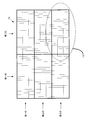
- FIG. 8 is a diagram illustrating an example of an arrangement of image frames of a particularly desirable intermediate image in the embodiment according to the present invention.
- the intermediate image 15 for each viewpoint includes, for example, a first viewpoint image in the first column of the first row, a second viewpoint image in the first column of the second row, and a first row of the third row.
- the third viewpoint image in the column, the fourth viewpoint image in the second column of the first row, the fifth viewpoint image in the second column of the second row, and the sixth viewpoint image in the second column of the third row. are arranged in tiles.
- the total number of subpixels constituting the stereoscopic image and the total number of subpixels on the image frame in which the intermediate image is arranged in a tile shape are the same both vertically and horizontally, there is no useless pixel, and each viewpoint Since the pixels are arranged together, there is no interference between different viewpoints, and irreversible compression can be used.
- the resolution and aspect ratio of the autostereoscopic display (stereoscopic image) and the image frame in which the intermediate image is arranged in a tile shape are the same.
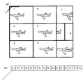
- FIG. 9 is a diagram showing an example in which a plurality of viewpoint images are arranged as they are in a tile-shaped image frame, and is a diagram for comparison with the image frame of the intermediate image described above.
- the resolution of the display that finally outputs is 16: 9
- the aspect ratio of the viewpoint image for one viewpoint in FIG. 9A is also 16: 9
- the entire image frame is 32:27.
- the RGB sub-pixels constituting the RGB staircase-arranged pixel unit are arranged in parallel in the RGB direction. Since the pixel unit is configured, the total number of pixels in the vertical direction is 1/3. Furthermore, when the number of viewpoints is 6, for example, the total number of pixels in the horizontal direction is
- the glue width is added to both sides of the image for each viewpoint.
- the ratio must be the same, and the resolution of the images at each viewpoint must be reduced so that the resolutions are the same when arranged in tiles.
- the viewpoint image for generating the stereoscopic image has a low resolution, and the quality of the stereoscopic image is significantly reduced.
- the present invention since an intermediate image is generated from high-quality viewpoint images, it is possible to completely maintain a resolution that is indispensable for stereoscopic image generation.
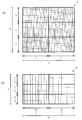
- FIG. 10 is a diagram illustrating an example of an image frame including a plurality of intermediate images.
- the image frames are shown when a stereoscopic image is generated from 2 viewpoints to 5 viewpoints and 7 viewpoints to 11 viewpoints, respectively, and the aspect ratio is the same as that of the stereoscopic image if the pixels of each viewpoint are arranged in tiles in the frame.
- An image file can be created.
- the stereoscopic image is composed of two viewpoints
- 2/3 of the intermediate image of one viewpoint is displayed on the first row tile and 1/3 of the intermediate image of one viewpoint is displayed on the first tile of the second row.
- 1/3 of the intermediate image of the two viewpoints is arranged on the second tile connected to the second tile, and 2/3 of the intermediate image of the two viewpoints is arranged on the tile of the third row.
- an intermediate image of each viewpoint is arranged on each row of tiles. If the stereoscopic image is composed of 4 to 6 viewpoints, the first tile connected to the intermediate image of 1 to 3 viewpoints and the intermediate image of 1 to 3 viewpoints from the first tile to the third line in the first tile of each line.
- the intermediate images of the remaining viewpoints are arranged on the arranged tiles.
- the first tile from the first row connected to the intermediate image of the first to third viewpoints is connected to the first tile of the third row on the first tile of each row.
- the intermediate images of the remaining viewpoints are arranged on the tiles arranged in the first to third rows connected to the intermediate images of the 4th to 6th viewpoints and the intermediate image of the 4th to 6th viewpoints.
- a part or all of the intermediate images are arranged on tiles in each row in order from one viewpoint.
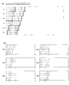
- FIG. 11 is a diagram showing an arrangement example of RGB staircase arrangement pixel units.
- FIG. 11A is a diagram illustrating an example of an RGB staircase-arranged pixel unit in which subpixels constituting a pixel unit of a viewpoint image from 1 viewpoint to 6 viewpoints are arranged in a staircase in contact with corners in an oblique direction. It is composed of 3 subpixels in 3 rows and 1 column.
- subpixels constituting the RGB staircase-arranged pixel unit are arranged in the horizontal direction to constitute an RGB parallel-arranged pixel unit.
- the RGB staircase-arranged pixel units of the same viewpoint arranged in a staircase in contact with the RGB staircase-arranged pixel units at the corners are also arranged horizontally in the RGB direction as shown in the figure,
- the RGB parallel arrangement pixel units are arranged in a staircase in contact with the corner in an oblique direction to form an intermediate image.
- FIG. 11B is a diagram showing an example of an RGB staircase-arranged pixel unit composed of 6 subpixels in 3 rows and 2 columns.
- a group of subpixels in the first column constituting the RGB staircase-arranged pixel unit is first arranged in the horizontal direction to form an RGB parallel-arranged pixel unit
- a group of sub-pixels in the second column is arranged so as to be further connected to the RGB parallel arrangement pixel units in the horizontal direction.
- RGB staircase-arranged pixel units of the same viewpoint arranged in a staircase in contact with the RGB staircase-arranged pixel units at the corners
- a group of subpixels in the first column is first arranged in the horizontal direction as shown in the figure.
- An RGB parallel arrangement pixel unit is configured, and a collection of subpixels in the second column is arranged so as to be further connected to the RGB parallel arrangement pixel unit in the horizontal direction.
- FIG. 11C is a diagram showing an example of an RGB staircase-arranged pixel unit composed of 9 subpixels in 3 rows and 3 columns.
- a group of subpixels in the first column constituting the RGB staircase-arranged pixel unit is first arranged in the horizontal direction to obtain an RGB parallel-arranged pixel unit.
- a group of subpixels constituting the RGB staircase-arranged pixel unit in the second column is arranged so as to be connected to the RGB parallel-arranged pixel unit in the horizontal direction.
- a group of sub-pixels constituting the RGB staircase-arranged pixel unit in the third column is arranged so as to be connected to each other.
- the RGB staircase-arranged pixel units shown in FIG. 11 it is desirable to obtain RGB values from a plurality of viewpoint images for each subpixel as shown in FIG. This prevents a decrease in resolution (for example, in FIG. 11B, the horizontal resolution is halved compared to FIG. 11A) due to the calculation and acquisition of RGB values in pixel units. And a clear stereoscopic image can be provided to the user.
- the subpixel is usually a vertically long rectangle at a ratio of 1: 3, but the shape of the subpixel is a circle, a circle, a V shape, or a shape obtained by rotating W by 90 degrees (see FIG. 51) (refer to the example shown in FIG.
- RGB staircase-arranged pixel unit in which three subpixels are arranged in a row.
- a mask with a wide slit and hole width of the parallax barrier for peeping a stereoscopic image and an arrangement interval thereof is created, and three subpixels (b It is desirable to generate RGB staircase-arranged pixel units arranged in two rows as in () or in three rows as in (c).
- the three-dimensional image is generated by arranging the subpixels constituting the RGB parallel arrangement pixel unit of the intermediate image transmitted from the optical disk such as BLU-RAY DISC (registered trademark), the server or the first information processing apparatus described above. This is done by changing the arrangement for stereoscopic viewing. That is, the sub-pixels constituting the RGB parallel arrangement pixel unit are rearranged in a staircase again to constitute the RGB staircase arrangement pixel unit. In this case, the stereoscopic image generation table relating the positions of these sub-pixels It is desirable to use
- the intermediate image generation table shown in FIG. 7 is used as a stereoscopic image generation table because the positions of the subpixels constituting the RGB parallel arrangement pixel unit and the positions of the subpixels constituting the RGB staircase arrangement pixel unit are related. It is possible.
- the RGB staircase arrangement pixel unit is generated again to generate a stereoscopic image.
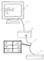
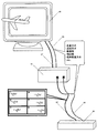
- FIG. 12 is an external view showing an example of the embodiment of the stereoscopic image generating apparatus 61 according to the present invention.
- the stereoscopic image generating device 61 is electrically connected by a video cable 67 between a general image output device 63 and a general stereoscopic image display device 65 (display).
- a general image output device 63 Connected to and used to receive images of a plurality of viewpoints transmitted as image signals (image input signals) from the image output device 63, and control information (scanning method, number of viewpoints, resolution, pixel arrangement method, etc.) set in advance Information) is converted into a pixel arrangement for stereoscopic image display, and the image after the pixel arrangement conversion is transmitted to the stereoscopic image display device 65 as an image signal (image output signal).
- the video cable 67 that electrically connects the stereoscopic image generation device 61, the image output device 63, and the stereoscopic image display device 65 is specifically the image output device 63 and the stereoscopic output of a standard such as VDI or HMVI.
- a cable for electrically connecting the image display device 65 and transmitting an image signal a cable that has been widely used can be used.
- FIG. 13 is an external view showing an example of another embodiment of the stereoscopic image generating apparatus 61 according to the present invention.
- the stereoscopic image generating device 61 receives a control signal by further electrically connecting to either one or both of an image output device 63 and a stereoscopic image display device 65 by a control cable 69.
- the control signal means a signal that gives control information other than an image such as a scanning method, a resolution, the number of viewpoints, and a pixel arrangement method to the stereoscopic image generating device 61.
- control cable 69 that is conventionally used as the control cable 69 for electrically connecting the image output device 63 and the stereoscopic image display device 65 of the standard such as i / LINK or serial is used. be able to.
- the video cable 67 and the control cable 69 have been described as separate cables in the figure, but these cables may be bundled to form a single cable.
- the image output device 63 uses the existing image output technology as it is. That is, the image output device 63 is an existing set-top box that acquires moving images by terrestrial broadcasting, satellite broadcasting, streaming or downloading from the Internet, or a stand-alone DVD player or Blu-ray (registered trademark) player. It is preferable to use a playback device such as a device having a recording function.
- the stereoscopic image display device 65 (display) be used as it is without any improvement on the existing stereoscopic image display device. That is, the stereoscopic image display device 65 is an autostereoscopic image display device such as a liquid crystal display, a plasma display, or an organic EL display that employs an existing parallax barrier method or lenticular method, or a two-viewpoint image at high speed. It is preferable that they are displayed alternately and viewed through shutter-type glasses.
- the stereoscopic image generating apparatus 61 according to the present invention can be used in addition to the stereoscopic image display apparatus described above.
- FIG. 14 is a diagram showing an example of a multi-viewpoint image received as an image signal by the stereoscopic image generating apparatus 61 according to the present invention.
- This is a recommended standardized tile format for multi-viewpoint images according to the present invention, in which only pixels to be read out from multi-viewpoint images are arranged for conversion to a pixel arrangement for stereoscopic image display.
- a predetermined compressed file is generated after being arranged in a tile format.
- the resolution is arbitrary, and usually the compression standard MPG2, which is lossy compression, is often used.
- an intermediate image may be generated in a tile format corresponding to an arbitrary number of viewpoints to form a multi-viewpoint image.
- an image having an arbitrary resolution with a 16: 9 aspect ratio is set to horizontal 960 pixels and each vertical 360 pixels. It is desirable to create an intermediate image of the viewpoint and convert it to a pixel arrangement for stereoscopic image display.
- the resolution of the six-view tile image is 1920 ⁇ 1080, and the tile image can be received as a high-definition image and converted into a stereoscopic image with the least image quality loss.
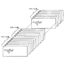
- FIG. 15 is a diagram showing an example of a moving image of a plurality of viewpoints received as a moving image signal by the stereoscopic image generating device 61 according to the present invention.
- a moving image is well known and can be created by multi-streaming of the compression standard MPG4.
- a plurality of moving images synchronized with one file can be recorded.
- the received intermediate images from one viewpoint to N viewpoints are stored in a storage unit in a predetermined arrangement and converted into a pixel arrangement for stereoscopic image display.
- FIG. 16 is a diagram showing an example of a moving image of a plurality of viewpoints received as a moving image signal by the stereoscopic image generating device 61 according to the present invention.
- the moving images of multiple viewpoints are repeatedly formed in the time direction by assigning the moving images of the respective viewpoints to each successive frame.
- the received intermediate images from one viewpoint to N viewpoints are sequentially stored in the storage means and converted into a pixel arrangement for stereoscopic image display.
- FIG. 17 is a diagram showing a first example of a multi-viewpoint intermediate image in which pixel information 71 is embedded, which is received as an image signal by the stereoscopic image generating device 61 according to the present invention.
- the pixel information is a predetermined encryption and defines information such as 2D image distinction, resolution, and the number of viewpoints. It is embedded in order to notify a stereoscopic image generation device or a converter (stereoscopic image generation device) whether a stereoscopic image or a normal image.
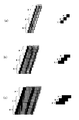
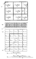
- FIG. 5A is a diagram showing an embedding position of the pixel information 71 on the image.
- the pixel information 71 is embedded in the upper left corner of the image.
- the embedding position of the pixel information 71 is based on a predefined arrangement pattern, it is not always necessary to be at the upper left end, but the end of the image is an image output device connected to the stereoscopic image generating device 61. Since it is a portion that overlaps with the 63 monitor frames and is invisible to the user, there is an advantage that even if the pixel information 71 is embedded, the display of the stereoscopic image to the user is not affected.
- FIG. 5B is an enlarged view showing the embedded pixel information 71.
- the pixel information 71 is embedded in the horizontal line without any gap. However, although not shown, it may be embedded at a predetermined interval.
- FIG. 18 is a diagram showing a second example of a multi-viewpoint intermediate image in which pixel information 71 is embedded, which the stereoscopic image generating apparatus 61 according to the present invention receives as an image signal.
- (A) in the figure is a diagram showing an embedding position of the pixel information 71 on the image.
- FIG. 5B is an enlarged view of a portion where the pixel information 71 is embedded.
- a pixel matrix 73 in which a plurality of pixel information 71 defined as the same image information is continuously arranged in the XY direction is embedded.
- FIG. 10C is an enlarged view showing one of the pixel matrices 73 in FIG. A 3 ⁇ 3 matrix surrounded by a central thick frame is a pixel matrix 73, and nine pieces of pixel information Cm ⁇ n in which the same image information is defined are arranged.
- image information is analyzed from pixel information 71 at the center of the pixel matrix 73 indicated by a circle.
- the position of the pixel information 71 at the center of the pixel matrix 73 is suitably specified by specifying the XY coordinates of the pixel information 71 based on a predefined arrangement pattern.
- image information may be obtained from an average value of a plurality of pieces of pixel information 71 in the pixel matrix 73.
- FIG. 19 is a diagram showing a third embodiment of an intermediate image of a plurality of viewpoints embedded with pixel information 71, which is received as an image signal by the stereoscopic image generating device 61 according to the present invention.
- (A) in the figure is a diagram showing an embedding position of the pixel information 71 on the image.
- FIG. 5B is an enlarged view of a portion where the pixel information 71 is embedded.
- FIG. 10C is an enlarged view showing one of the pixel matrices 73 in FIG.
- pixel information 71 defined as image information is arranged in the center of the pixel matrix 73, and an intermediate portion between the pixel adjacent to the pixel matrix 73 and the pixel information 71 in the outer periphery of the pixel matrix 73.
- Value pixel information 71 is embedded.
- FIG. 20 is a diagram showing a fourth embodiment of an intermediate image of a plurality of viewpoints embedded with pixel information 71, which is received as an image signal by the stereoscopic image generating apparatus 61 according to the present invention.
- (A) in the figure is a diagram showing an embedding position of the pixel information 71 on the image.
- FIG. 5B is an enlarged view of a portion where the pixel information 71 is embedded.
- the pixel matrix 73 is 2 ⁇ 3, and compared with the pixel matrix 73 of the third embodiment, the pixel information 71 in the upper line is removed and arranged at the upper end of the image. Yes.
- Such an embodiment is suitable because the influence on the image is reduced when the area occupied by the pixel matrix 73 is reduced.
- FIG. 10C is an enlarged view showing one of the pixel matrices 73 in FIG.
- the pixel information 71 defining the image information is arranged in the center of the row above the pixel matrix 73, and the pixel information 73 is an intermediate value between the pixel adjacent to the pixel matrix 73 and the pixel information 71 on the outer periphery of the pixel matrix 73. Pixels that are interpolated with predetermined weights are arranged on both pixels.
- weighting means multiplying the value of the pixel information 71 by a predetermined number when obtaining an intermediate value in order to analyze the image information defined by the pixel information 71 more reliably.
- the weighting is double the value of the pixel information 71, but may be tripled or quadrupled as necessary. It should be noted that weighting is possible in the third embodiment.
- 21 and 22 are diagrams for explaining what kind of information the image information actually means in the above embodiment.
- codes C 0 to C 23 are used as determination codes (headers).
- the combination of the RGB values of the determination code is a combination that is almost impossible in nature, so that the central processing unit 33 recognizes that the pixel information is embedded as defining image information. become able to.
- Codes C 24 to C 29 are used for parity check as shown in FIG.
- Codes C 30 to C 89 mean control information as specifically shown in FIG.
- the codes C 90 to C 95 are used for parity check as shown in FIG.
- the central processing unit 33 identifies the position where the pixel information 71 is embedded based on a predetermined arrangement pattern, determines the presence or absence of a header for collating image information, and analyzes the image information when there is a header.
- FIG. 23 is a flowchart showing a method for discriminating between a normal planar image and a multi-viewpoint intermediate image by always embedding pixel information 71 defined as image information in the multi-viewpoint intermediate image.
- the frames before and after the frame at the moment when the intermediate image of the multiple viewpoints starts, and the frames before and after the frame at the time of the end of the intermediate image of the multiple viewpoints may be embedded.
- the central processing unit 33 when receiving an image, the central processing unit 33 analyzes the presence / absence of a header at a predetermined position for each frame based on a predetermined pixel arrangement pattern defined in advance.
- the frame When there is a header, the frame is an intermediate image frame of a plurality of viewpoints, and image information is defined in the frame. Therefore, the central processing unit 33 analyzes the image information.
- the frame When there is no header, the frame is a normal planar image frame, and no image information is defined in the frame, so the central processing unit 33 does not analyze the image information.
- the central processing unit 33 proceeds to analysis of the next frame.
- a predetermined optimum stereoscopic visible position and a predetermined oblique moire elimination position are set at positions where the most people can be pooled, and back calculation is performed based on these values. Since it is possible to determine the distance from the image display surface of the display to the parallax barrier and the interval in the horizontal direction of one or more visible light transmission parts, the image is presented at a predetermined oblique moire elimination position. The subject can always visually recognize the predetermined position of the pixel displaying the image of the predetermined viewpoint through the visible light transmitting portion of the parallax barrier, and the moire is completely eliminated at the predetermined moire elimination position. become.
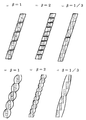
- the “visible light transmitting portion” is a portion that transmits visible light provided on a surface that does not transmit visible light constituting the parallax barrier. That is, the “visible light transmitting portion” referred to in the present invention means that the shape of the edge of the slit is a linear shape, a staircase shape, a zigzag shape, or a shape having a continuous circular arc or elliptical arc shape (a dumpling shape). good. Further, the shape of the arrangement of the slits may be a sine arc. Furthermore, the visible light transmitting portion may be a hole type that is independently arranged on the parallax barrier.
- not transmitting visible light means any one of the optical characteristics of (1) absorbing visible light, (2) diffusely reflecting visible light, and (3) specularly reflecting visible light.
- the “optimal stereoscopic view position” is a position where the person who presents the image can obtain the stereoscopic effect particularly effectively. That is, at the optimum stereoscopic visible position, both eyes of the image presentation target person visually recognize the center of the stereoscopic display pixel for the viewpoint to be visually recognized through the visible light transmitting portion of the parallax barrier.
- the “moire elimination position” refers to a position at which a subject can be made to visually recognize a stereoscopic image effectively in a form in which moiré is completely reduced, and an image is displayed at a predetermined moire elimination position.
- the presentation target person can visually recognize a predetermined position of a stereoscopic display pixel that always displays an image of a predetermined viewpoint through the visible light transmitting portion of the parallax barrier with either the left or right eye.
- the moiré elimination position even if the image presentation subject moves to the left or right or up and down in parallel with the autostereoscopic display, the effect of moiré elimination does not change.
- the concept of the moire elimination position includes an oblique direction moire elimination position and a horizontal direction moire elimination position, which will be described later.
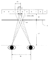
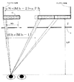
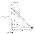
- Vh is the width of the effective visible region that is visible with one eye through the visible light transmitting portion of width Sh
- ⁇ Ph is the distance between the centers of the three-dimensional display pixels that display images of adjacent viewpoints
- Z is the image display surface of the display
- L1 is the distance from the image presentation target person to the parallax barrier at the optimal stereoscopic view position
- W is the distance between the pupils of the left and right eyes of the image presentation target person
- K is the image presentation target person The distance between the gazing points of both eyes is shown.
- a one-dot chain line extending from one eye of the image presentation target person toward the display indicates a gaze line of the image presentation target person.
- the optimal stereoscopic viewing position may be a position where the image presentation target person wants to visually recognize the autostereoscopic image particularly effectively in consideration of the application and installation location of the stereoscopic image display device. That is, the distance L1 from the optimal stereoscopic view position to the parallax barrier can take an arbitrary value.
- the distance W between the eyes of the left and right eyes of the image presentation subject is 60 to 65 mm if the main subject of the stereoscopic image is Western, 65 to 70 mm if Asian, and 50 if children. What is necessary is just to set and calculate to about ⁇ 60 mm.
- the distance ⁇ Ph between the centers of the stereoscopic display pixels that display the images of the adjacent viewpoints for example, constitutes one stereoscopic display pixel by three subpixels
- the value of ⁇ Ph is 1Ph when pixels are arranged in a stepwise manner in an oblique direction.
- the value of the width Vh of the effective visible region that is visually recognized with one eye of the image presentation target person through the visible light transmitting portion of the parallax barrier is determined.
- the effective visible region refers to a region on the image display surface that can be visually recognized through the visible light transmission part of the parallax barrier at the optimal stereoscopic viewing position. That is, it is the range of the display intended to be visually recognized by the image presentation target person at the optimum stereoscopic visible position.
- the width Vh of the effective visible region occurs when a person moves, when the image changes from one viewpoint to another, and when the left and right eyes view an image of the opposite viewpoint.
- Vh if Vh is large, the viewpoint is changed and the jump point is reduced.
- a stereoscopic display pixel that is different from the stereoscopic display pixel that displays an image of an adjacent viewpoint that should be visually recognized by both eyes.
- the stereoscopic effect is poor because the eyes are visually recognizing the same image.
- the value of Vh when the value of Vh is small, the stereoscopic effect of the image is enhanced and the stereoscopic image is clearly displayed, but the jump point is increased.
- the above effects are greatly different depending on the shape and arrangement of the slit or the visible light transmitting portion.
- the effective visible region width is appropriately widened according to the usage of the stereoscopic image, etc., so that the stereoscopic image can be provided more effectively in accordance with the demand and situation of the image presentation target person. be able to.
- the gaze line (FIG. 24, one-dot chain line) of the image presentation target person visually recognizes the center of each stereoscopic display pixel. Is the same value as ⁇ Ph.
- the value of the distance Z from the image display surface of the display to the parallax barrier is obtained based on the determined value of the effective visible region width Vh.
- Z is calculated by the following formula.
- Z is the distance from the display surface to the parallax barrier even when a processing such as transfer prevention is applied to the display surface of the stereoscopic image display device or a transparent sheet such as reflection prevention is applied. .
- the value of the lateral width Sh of the visible light transmitting portion is obtained.
- L1 is expressed as the following formula.
- the height Sh of the visible light transmitting portion is expressed by the following mathematical formula.
- the value of Sh can be obtained from the values of W, ⁇ Ph, and Vh.
- the shape of the edge of the slit which is the visible light transmitting portion constituting the parallax barrier, is a stepped shape, a circular arc shape, an elliptical arc shape, a polygonal continuous shape, or the parallax barrier.
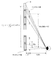
- the height Vv of the effective visible region of the parallax barrier is the range of the display visually recognized through the visible light transmitting portion having the height Sv at the optimum stereoscopic viewing position, and the value is a place where the autostereoscopic display is installed. It can be set to a predetermined value in accordance with the above conditions.
- the value of the effective visible region may be reduced.
- one unit of a plurality of continuous slit edges or a visible light transmitting portion may be used for one subpixel, or two or more sublights may be used.
- One continuous visible light transmitting portion or the plurality of hole-shaped visible light transmitting portions may be used for each pixel.
- the height Vv of the effective visible region is determined through the height of the visible light transmitting portion. The range of the display that is visible.
- the height Sv of the visible light transmitting portion is expressed by the following formula.
- the value of the height Sv of the visible light transmitting portion can be calculated backward by first determining the value of the effective visible region height Vv.
- the height Sv of the visible light transmission part can be obtained by the following formula based on the interval Hv of the visible light transmission part.
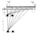
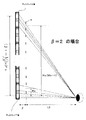
- the distance Hh between a plurality of visible light transmitting portions constituting the parallax barrier adjacent in the horizontal direction is obtained based on the distance from the predetermined oblique moire elimination position to the parallax barrier based on L2. .
- the person who presents the image is a three-dimensional image forming the RGB staircase-arranged pixel block 13 at the left end of the display through the visible light transmitting portion of the parallax barrier with one eye (left eye) at a predetermined oblique direction moire elimination position.
- the display pixel and the stereoscopic display pixel constituting the RGB staircase arrangement pixel block 13 at the right end of the display are visually recognized, and the stereoscopic display pixel visually recognized by the image presentation target person displays an image of the same viewpoint. To do.
- the image presentation target person does not visually recognize the moire on the screen.
- the parallax barrier of the RGB staircase arranged pixel block 13 at the right end of the display is set.
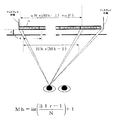
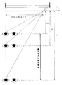
- the number Mh of visible light transmitting parts in the horizontal direction up to the visible light transmitting part can be expressed by the following expression using the number N of viewpoints for displaying a stereoscopic image and the horizontal resolution Ir.
- 3Ir obtained by multiplying the horizontal resolution Ir by 3 (R, G, B) is the number of sub-pixels in the horizontal direction.
- the sub-pixel at the right end of the display does not display the image of the seventh viewpoint, which is the last viewpoint of the viewpoint.
- the first viewpoint may be used, and in this case, it is necessary to calculate by subtracting the number of sub-pixels that display the image of the first viewpoint.
- adding 1 at the end is an integer obtained by subtracting 1 from the total number of subpixels even when the subpixel displaying the image of the first viewpoint is not at the right end of the display. This is to compensate for the lack of one Mh value.
- the RGB staircase at the right end of the display is a stereoscopic display pixel that displays an image of the same viewpoint as this.
- the distance to the center of the visible light transmitting part with respect to what constitutes the arranged pixel block 13 is a value obtained by multiplying Hh (the distance between visible light transmitting parts in the horizontal direction) by (Mh ⁇ 1).
- the distance to the center of the RGB staircase arranged pixel block 13 at the right end of the display is the number of viewpoints of an image for generating a naked-eye stereoscopic image, and the distance between adjacent viewpoints. This can be expressed by the following equation using the distance ⁇ Ph between the centers of the three-dimensional display pixels that display the image.
- the value of the interval Hh between the plurality of visible light transmitting portions constituting the parallax barrier adjacent in the horizontal direction can be obtained.
- the person who presents the image displays the RGB staircase-arranged pixel block 13 at the left end of the display in the same manner as the predetermined oblique moire elimination position (L2).
- 3D display pixels that display an image for the first viewpoint are visually recognized through the visible light transmitting portion of the parallax barrier, but through the visible light transmitting portion as the viewpoint shifts to the right. Therefore, not the stereoscopic display pixels for the first viewpoint, but the stereoscopic display pixels for other viewpoints are visually recognized.
- Hh can be obtained by the following equation.
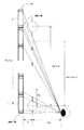
- Hh Similarly to the determination of the value of Hh based on L2n, it is the distance from the position where one moire in the oblique direction occurs to the parallax barrier, and the parallax is more of the two types of positions.
- the value of Hh can be obtained based on a predetermined distance L2f from a position far from the barrier to the parallax barrier.
- the person who presents the image displays the 3D display pixels constituting the RGB staircase-arranged pixel block 13 at the left end of the display in the same manner as the predetermined moire elimination position (L2) in the diagonal direction.
- the one that displays the image for the first viewpoint is viewed through the visible light transmission part of the parallax barrier, but for the stereoscopic display for the first viewpoint through the visible light transmission part as the viewpoint shifts to the right. Instead of this pixel, the stereoscopic display pixels for other viewpoints are visually recognized.
- the distance Hh between the plurality of visible light transmitting portions constituting the parallax barrier adjacent in the horizontal direction can be obtained based on the value of the point (L2n ⁇ L2f) where one moire occurs, for example,
- the region from the point L2n to the point L2f can be designated as a moire appropriate elimination region, and a point where the stereoscopic image can be visually recognized particularly effectively can be clearly shown to the image presentation target person.
- the moiré elimination area in a range where the most people can be collected, it is possible to attract the attention of the image presentation target person.
- the shape of the edge of the slit which is the visible light transmitting portion constituting the parallax barrier, is a stepped shape, a circular arc shape, an elliptical arc shape, a polygonal continuous shape, or the parallax barrier.
- the shape of the visible light transmitting portion to be formed is a hole shape formed independently, based on the value of the distance L3 from a predetermined horizontal moire elimination position to the parallax barrier, the parallax A method for obtaining the value of the interval Hv between the continuous visible light transmitting portions or the plurality of hole-shaped visible light transmitting portions connected in the vertical direction of the barrier will be described.
- the alternate long and short dash line in FIG. 34 indicates the gaze line of the image presentation target person
- K indicates the distance between the upper and lower gaze points of the image presentation target person.
- the value of the distance L3 from the parallax barrier to the predetermined horizontal moiré elimination position is determined depending on what distance from the display the user wants to provide a stereoscopic image with the moiré especially eliminated.
- the image presentation target person always gazes at the center of the sub-pixel through the visible light transmission part of the parallax barrier. It is equal to the subpixel height Pv.
- ⁇ represents the number of visible light transmission parts in the vertical direction corresponding to one subpixel. For example, as shown in FIGS. 35 (a) and 35 (d), one visible for one subpixel. When a light transmission part is formed, ⁇ is 1. Also, as shown in FIGS. 35B and 35E, when two visible light transmitting portions are formed for one subpixel, ⁇ is 2. Furthermore, as shown in FIGS. 35C and 35F, when one visible light transmitting portion is formed for three subpixels, ⁇ is 1/3.
- ⁇ is a unit of the visible light transmitting portion having the continuous shape corresponding to one subpixel or the number of the visible light transmitting portions having the plurality of hole shapes in the vertical direction.
- the number of visible light transmitting portions provided for one subpixel is an integer. In the case where one visible light transmission portion is provided for a plurality of subpixels, it is desirable to provide an integer number of visible light transmission portions for one stereoscopic display pixel.
- Hv is represented by the following equation.
- the shape of the edge of the slit which is the visible light transmitting portion constituting the parallax barrier, is a stepped shape, a circular arc shape, an elliptical arc shape, a polygonal continuous shape, or the parallax barrier.
- the shape of the visible light transmitting portion to be formed is a hole shape formed independently, the distance from the position where one horizontal moire occurs to the parallax barrier, Based on the value of L3n, a predetermined distance from the position closer to the parallax barrier to a position closer to the parallax barrier among the positions is connected to the vertical direction of the parallax barrier. A method of obtaining the value of the interval Hv between the visible light transmitting parts having the shape or the plurality of holes will be described.
- the image presentation target person visually recognizes the sub-pixel at the lower end of the display through the visible light transmitting portion of the parallax barrier, similarly to the predetermined horizontal moire elimination position (L3).
- L3 the predetermined horizontal moire elimination position
- the viewpoint shifts upward, not the sub-pixel that should be visually recognized at the point L3 but the sub-pixel above it is visually recognized through the visible light transmitting portion.
- the virtual subpixel 16 is assumed above the upper end of the display through the visible light transmitting portion through which visible light is transmitted when the subpixel at the upper end of the display is viewed at the point L3, the virtual subpixel 16 Will be visually recognized. Since such a cycle occurs once, it is considered that moire occurs once in L3n.
- the visible light transmitting portion of the shape that is continuous in the vertical direction from the visible light transmitting portion of the shape corresponding to the sub pixel at the upper end of the display to the visible light transmitting portion of the shape corresponding to the sub pixel at the lower end of the display.
- the number Mv of the visible light transmitting parts having one unit or the plurality of hole shapes will be described.
- Mv is for stereoscopic display in which an image presentation target person displays an image of the same viewpoint on a display at one point in a predetermined horizontal moire elimination position (L3). This is the number of visible light transmission parts of the parallax barrier necessary for visually recognizing all the pixels and obtaining a stereoscopic image effect.
- the number of units of the continuous visible light transmitting portion of the shape means, for example, when the shape of the slit that is the visible light transmitting portion of the parallax barrier is an elliptical arc, the elliptical arcs are the same It means the number of 3D display pixels for displaying the viewpoint image and the number of pixels formed on the corresponding slits. Also. “The number of the plurality of hole-shaped visible light transmitting portions” refers to how many holes-shaped visible light transmitting portions are formed corresponding to the arrangement of the three-dimensional display pixels displaying the same viewpoint image. Means number. Jr indicates the vertical resolution of the display.
- Mv can be expressed by the equation Jr ⁇ ⁇ .
- the shape of the edge of the slit which is a visible light transmitting portion constituting the parallax barrier
- the shape is a hole shape formed independently, the distance from the position where a single moire in the horizontal direction occurs to the parallax barrier.
- a predetermined distance from a position far from the lux barrier to the parallax barrier is connected to the vertical direction of the parallax barrier in the continuous visible light transmitting portion or the plurality of hole shapes.
- the image presentation target person visually recognizes the subpixel at the lower end of the display through the visible light transmitting portion of the parallax barrier, similarly to the predetermined horizontal moire elimination position (L3).
- L3 the predetermined horizontal moire elimination position
- the viewpoint shifts upward, not the sub-pixel that should be visually recognized at the point of L3 but the sub-pixel below it is visually recognized through the visible light transmitting portion.
- the subpixel below the upper end of the display is viewed through the visible light transmitting portion through which visible light passes when the subpixel at the upper end of the display is viewed at the point L3. Since such a cycle occurs once, it is considered that moire occurs once in L3n.
- Hv Hpv / ⁇ ( ⁇ is a natural number), where Hpv is the interval between subpixels connected in the vertical direction.
- L3n and L3f can be determined based on the value of L3. This will be described with reference to FIGS.
- the distance from the lower end of the display to the upper end of the display is obtained. Therefore, the distance from the center of the subpixel at the lower end of the display to the center of the virtual subpixel 16 above the upper end of the display can also be expressed as (Pv ⁇ Jr).
- the visible light of the parallax barrier that is transmitted when the image presentation target person visually recognizes the stereoscopic image is more than the number of subpixels in the vertical direction.
- the number of transmissive portions is small by one, the image presentation target person visually recognizes all the sub-pixels through the visible light transmissive portion.
- L3n is a point where a cycle of moire generation in the vertical direction occurs once.
- the distance from the center of the visible light transmitting portion of the parallax barrier corresponding to the sub pixel at the lower end of the display to the visible light transmitting portion of the parallax barrier corresponding to the virtual sub pixel 16 at the upper end of the display is It can be expressed as Hv ⁇ (Jr ⁇ 1).
- L3n is represented by the following equation.
- the visible light transmission of the parallax barrier that is transmitted when the image presentation target person visually recognizes the stereoscopic image is larger than the number of vertical subpixels. Although the number of parts is one, the image presentation target person visually recognizes all the sub-pixels through the visible light transmitting part.
- the distance from the center of the visible light transmitting portion of the parallax barrier corresponding to the sub-pixel at the lower end of the display to the visible light transmitting portion of the parallax barrier corresponding to the virtual sub-pixel 16 at the upper end of the display is It can be expressed as Hv ⁇ (Jr + 1).
- L3f can be expressed by the following equation if the same idea as the equation for obtaining L3n is used.
- a range from L3n to L3f is a moire appropriate elimination region in the vertical direction.
- the horizontal resolution Ir is 1920 and the vertical resolution Jr is 1080.
- the horizontal width Ph of the subpixel is 0.15375 mm
- the distance L1 from the parallax barrier to the optimum stereoscopic view position is 2500 mm
- the number N of viewpoints is 5
- the distance W between the left and right eye pupils of the image presentation target is 65 mm.
- the resolution Ir is 1920
- the vertical resolution Jr is 1080.
- the distances L2 and L3 from the parallax barrier to the moire elimination position in the oblique direction and the horizontal direction are also set to 2500 mm.
- L1, L2, and L3 are the same value, but L1, L2, and L3 are not necessarily the same value.
- the distance ⁇ Ph between the centers of the stereoscopic display pixels that display the images of the adjacent viewpoints is 1 Ph, and the width of the effective visible region that is visually recognized by one eye of the image presentation target person through the visible light transmitting portion of the parallax barrier. Vh is set to 1.2 Ph.
- Sh is obtained based on the obtained values of Z and Vh.
- the shape of the edge of the slit which is a visible light transmitting portion constituting the parallax barrier
- the shape is a hole shape formed by a plurality of independently, the value of the height Sv of the continuous visible light transmitting portion of the shape or the visible light transmitting portion of the plurality of hole shapes is obtained.
- the value of the height Vv of the effective visible region of the parallax barrier is ⁇ ⁇ Pv.
- ⁇ is a coefficient indicating the range of the sub-pixels visible through Sv, that is, the ratio of the height Vv of the effective visible region to the sub-pixel height Pv. In other words, the aperture ratio of the parallax barrier in the vertical direction.
- ⁇ is 0.9.
- one unit of the continuous visible light transmitting portion having the shape corresponding to one subpixel or the number ⁇ of the plurality of hole-shaped visible light transmitting portions in the vertical direction is 1.
- Vv is as follows.
- Sv is the following value.
- the distance from the predetermined oblique moire elimination position to the parallax barrier is obtained as follows as the spacing Hh between the plurality of slit regions constituting the parallax barrier adjacent in the horizontal direction. .
- the value of the interval Hh between the plurality of slit regions constituting the parallax barrier adjacent in the horizontal direction is the distance from the position where one moire in the oblique direction occurs to the parallax barrier, Among the positions, a predetermined distance L2n from a position closer to the parallax barrier to the parallax barrier or a predetermined distance L2f from a position farther from the parallax barrier to the parallax barrier is also obtained. be able to.
- the value of Hh is obtained by setting the predetermined value of L2n to 1000 mm and the value of L2f to 3000 mm.
- the value of Hh can be obtained by the following equation.
- the value of L2n can also be determined based on the value of the moire elimination position L2 in the oblique direction.
- the value of L2n is as follows.
- the value of L2f can be determined based on the value of the moire elimination position L2 in the oblique direction.
- the value of L2f is as follows.
- the shape of the edge of the slit which is a visible light transmission part constituting the parallax barrier, Stepwise or circular arc, elliptical arc, polygonal continuous shape, or the shape of the visible light transmitting part constituting the parallax barrier is a plurality of independently formed hole shapes, connected in the vertical direction.
- the value of the interval Hv between the continuous visible light transmitting portions having the shape or the plurality of hole-shaped visible light transmitting portions is obtained as follows.
- the interval Hv between the continuous visible light transmitting portions or the plurality of hole-shaped visible light transmitting portions connected in the vertical direction is determined from the position where one horizontal moire occurs.
- the distance L3n from the position closer to the parallax barrier to the parallax barrier, or from the position farther from the parallax barrier, The predetermined distance to the lux barrier can also be obtained based on the value of L3f.
- the value of Hv is obtained by setting the predetermined value of L3n to 1000 mm and the value of L3f to 3000 mm.
- the visible light transmitting portion having the shape corresponding to the sub-pixel at the lower end of the display is changed from the visible light transmitting portion corresponding to the sub-pixel at the upper end of the display at a predetermined horizontal direction moire elimination position.
- the value of the number Mv of one unit of the visible light transmitting part having the continuous shape in the vertical direction or the number of the visible light transmitting parts having the plurality of holes in the vertical direction is as follows.
- the value of Hv can be obtained by the following equation.
- L3n may be determined based on the value of the moire elimination position L3 in the horizontal direction.
- L3n is as follows.
- L3f can also be determined based on the value of the moire elimination position L3 in the horizontal direction.
- the value of L3f is as follows.
- the shortest distance L1n of the appropriate stereoscopic visible region is the following value.
- the longest distance L1f of the appropriate stereoscopic visible region is the following value.
- the appropriate stereoscopic visible region is 2078 mm to 4988 mm.
- L1n L1 has a relationship of approximately 0.8: 1.
- the L1n (the shortest distance to the optimum stereoscopic visible region), the L2n (the shortest distance to the moire appropriate elimination area in the oblique direction), and the L3n (the shortest distance to the moire appropriate elimination area in the horizontal direction).
- (distance) is set to the same distance.
- L1n, L2n, and L3n are different concepts as described above, they are not limited to the case where all of them are set to the same distance as described in the present embodiment.
- the horizontal resolution Ir is 1920
- the vertical resolution Jr is 1080
- the horizontal width Ph of the subpixel is 0.15375 mm
- the height of the subpixel is 0.46125 mm
- the number of viewpoints N is 5.
- the distance W between the pupils of the right and left eyes of the viewpoint and the image presentation target is 65 mm
- the distance from the parallax barrier to the optimal stereoscopic viewing position is 2500 mm
- the distance ⁇ Ph is 0.15375 mm
- the width Vh of the effective visible region visually recognized by one eye of the image presentation target person through the visible light transmission part of the parallax barrier is 0.1845 mm
- the image presentation target is through the visible light transmission part of the parallax barrier.
- the height Vv of the effective visible region visually recognized by a person is 0.415125 mm.
- a visible light transmitting portion of the parallax barrier to the RGB staircase arranged pixel block at the left end of the display at a predetermined oblique direction moire elimination position a visible light transmitting portion of the parallax barrier to the RGB staircase arranged pixel block at the right end of the display
- the number Mh of the visible light transmitting parts in the horizontal direction is 1152
- the number ⁇ in the left and right direction of the visible light transmitting parts corresponding to one subpixel is 1, which is continuous corresponding to one subpixel.
- One unit of the visible light transmitting portion having the shape or the number ⁇ of the plurality of hole-shaped visible light transmitting portions in the vertical direction is 1.
- L1n L1n
- L1n can be obtained by the following equation using Z, W, and Vh.
- L1n has the following value.
- L1f (the longest distance to the appropriate stereoscopic visible region) is the following value.
- the appropriate stereoscopic visible region is 2078 mm to 4988 mm.
- L2n and L3n are also set to 2078 mm, which is the same distance as L1n.
- the value of Z can be obtained based on the value of L1n.
- Z has the following value.
- the value of Hh can be obtained based on the value of L2n.
- Hh has the following value.
- the value of Hv can be obtained based on the value of L3n.
- Hv has the following value.
- the value of Sh can be obtained based on the following formula.
- Sh has the following value.
- Sv has the following value.
- 44 to 49 are diagrams for explaining an example of the shape of the slit of the parallax barrier.
- FIG. 44 is a diagram showing a case where the shape of the edge of the slit is stepped.
- the case where the shape of the slit edge is stepped means the case as shown in FIG. 44 (a), and the case where the shape of the slit edge is an arc is shown in FIG. 44 (b). Say such a case.
- the case where the shape of the slit edge is an elliptical arc refers to a case as shown as an example in FIGS. 45 (a) and 45 (b).
- the case where the shape of the slit edge is a shape in which polygonal openings are continuous refers to a case as shown as an example in FIGS. 46 (a) and 46 (b).
- the visible light transmitting portion is a hole-shaped opening formed with a plurality of independent shapes means that the periphery of the visible light transmitting portion is a parallax as shown as an example in FIGS. 47, 48 and 49. It is a state that is a hole surrounded by the mask portion of the Lux barrier.
Landscapes
- Engineering & Computer Science (AREA)
- Multimedia (AREA)
- Signal Processing (AREA)
- Physics & Mathematics (AREA)
- Optics & Photonics (AREA)
- Testing, Inspecting, Measuring Of Stereoscopic Televisions And Televisions (AREA)
- Devices For Indicating Variable Information By Combining Individual Elements (AREA)
- Controls And Circuits For Display Device (AREA)
- Stereoscopic And Panoramic Photography (AREA)
- Control Of Indicators Other Than Cathode Ray Tubes (AREA)
Abstract
Description

先ず、α=x-x1、β=x2-x、γ=y-y1、δ=y3-y、
視点画像のピクセルの中心点であるP1~4のRGB値をそれぞれC1~4とすると、PのRGB値は、線形補間により次式で表わされる。























次に、図42を参照して、前記L3nを求める。

L3n:(L3n+Z)と


















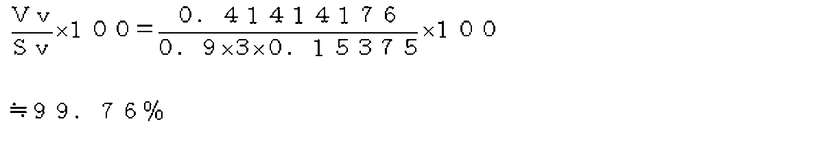













階段状もしくは円弧、楕円弧、多角形が連続した形状、または、前記パララックスバリアを構成する可視光透過部の形状が、独立して複数形成された穴形状である場合の、垂直方向に連接する、前記連続する前記形状の可視光透過部または前記複数の穴形状の可視光透過部の間隔Hvの値を以下のように求める。



























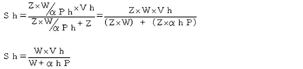


2 注視点
3 カメラ
5 視点画像
6 パララックスバリア
7 立体画像
9 画素ユニット
11 RGB階段配置画素ユニット
13 RGB階段配置画素ブロック
14 仮想画素
15 中間画像
16 仮想サブピクセル
17 RGB並列配置画素ユニット
19 画像フレーム
21 中間画像生成テーブル
23 立体画像生成テーブル
31 中間画像生成装置
33 中央処理装置
35 記憶装置
41 第一の情報処理装置
43 圧縮装置
45 送信装置
47 第二の情報処理装置
49 解凍装置
51 受信装置
61 立体画像生成装置
63 画像出力装置
65 立体画像表示装置
67 映像ケーブル
69 制御ケーブル
71 画素情報
73 画素マトリクス
75 元画像ファイル
77 画素埋め込み画像ファイル
Claims (13)
- 1視点からN視点までの複数の視点で撮影および/または描画した複数の視点画像から変換される立体画像を生成するために用いられる複数の中間画像を生成する中間画像生成方法であって、
サブピクセルが斜め方向にコーナーで接して3行で配列されたRGB階段配置画素ユニットを、水平方向に該1視点からN視点までを連接して配列したRGB階段配置画素ブロックを繰り返し配置して該立体画像を生成するために、
該RGB階段配置画素ユニットを構成するサブピクセルの各々のR値、G値、B値を、該RGB階段配置画素ユニットを構成するサブピクセルの配置位置に対応する、該複数の視点画像における対応位置近辺に配置された少なくとも1以上の画素ユニットを構成するサブピクセルのRGB値から補間して求め、
該RGB階段配置画素ユニットを構成するサブピクセルを水平方向にR、G、Bの順に並べて配列したRGB並列配置画素ユニットを、該複数の視点毎にまとめて配置する配置規則に従って配置して、該複数の視点毎の該中間画像を生成することによって、
該立体画像の該RGB階段配置画素ユニットと該複数の中間画像の該RGB並列配置画素ユニットの総数、またはそれぞれを構成するサブピクセルの総数が同数となる
ことを特徴とする中間画像生成方法。 - 前記RGB階段配置画素ユニットは、
各行毎のサブピクセルが1列であり、R値、G値、B値を有する3個の該サブピクセルから構成されており、
前記RGB並列配置画素ユニットは、
1行に、該3個のサブピクセルがR、G、Bの順に3列並べて配列されている
ことを特徴とする請求項1記載の中間画像生成方法。 - 前記RGB階段配置画素ユニットは、
各行毎のサブピクセルが2列であり、該2列の各列はR値、G値、B値を有する3個の該サブピクセルから構成されており、
前記RGB並列配置画素ユニットは、
1行に、該RGB階段配置画素ユニットの第一列に3行で配列された3個のサブピクセルがR、G、Bの順に3列並べて配列され、該配列に水平方向に連接して、該RGB階段配置画素ユニットの第二列に3行で配列された3個のサブピクセルがR、G、Bの順に3列並べて配列されている
ことを特徴とする請求項1記載の中間画像生成方法。 - 前記RGB階段配置画素ユニットは、
各行毎のサブピクセルが3列であり、該3列の各列はR値、G値、B値を有する3個の該サブピクセルから構成されており、
前記RGB並列配置画素ユニットは、
1行に、該RGB階段配置画素ユニットの第一列に3行で配列された3個のサブピクセルがR、G、Bの順に並べて配列され、該配列に水平方向に連接して、該RGB階段配置画素ユニットの第二列に3行で配列された3個のサブピクセルがR、G、Bの順に並べて配列され、該配列にさらに連接して、該RGB階段配置画素ユニットの第三列に配列された3個のサブピクセルがR、G、Bの順に並べて配列されている
ことを特徴とする請求項1記載の中間画像生成方法。 - 前記複数の中間画像を、画像フレームとして少なくとも縦方向に三等分割された第一行乃至第三行からなる複数のタイル状に配置することによって、
前記RGB階段配置画素ユニットを構成するサブピクセルと、前記RGB並列配置画素ユニットを構成するサブピクセルと、が、
前記立体画像と該複数の中間画像が配置された該画像フレームにおいて、縦横方向ともに同数となる
ことを特徴とする請求項1記載の中間画像生成方法。 - 前記複数の視点が2視点である場合においては、前記第一行のタイルに1視点の前記中間画像の2/3と、前記第二行の第1のタイルに1視点の該中間画像の1/3と連接した第2のタイルに2視点の該中間画像の1/3と、前記第三行のタイルに2視点の該中間画像の2/3を、
前記複数の視点が3視点である場合においては、各行のタイルに各視点の中間画像を、
前記複数の視点が4~6視点である場合においては、各行の先頭のタイルに1~3視点の該中間画像と、1~3視点の該中間画像に連接した第一行から第三行に配置されたタイルに残りの視点の該中間画像を、
前記複数の視点が7~9視点である場合においては、各行の先頭のタイルに1~3視点の該中間画像と、1~3視点の該中間画像に連接した該第一行から該第三行のタイルに4~6視点の該中間画像と、4~6視点の該中間画像に連接した第一行から第三行に配置されたタイルに残りの視点の該中間画像を、
配置し、
前記複数の視点が10視点以上である場合においても、同様に1視点から順に各行のタイルに該中間画像の一部または全部を配置する
ことを特徴とする請求項5記載の中間画像生成方法。 - 前記配置規則に代えて、前記立体画像の前記RGB階段配置画素ユニットを構成するサブピクセルの位置と、該複数の視点毎の中間画像の前記RGB並列配置画素ユニットを構成するサブピクセルの位置とを関連付ける、予め作成された中間画像生成テーブルを参照して、該RGB階段配置画素ユニットを構成するサブピクセルを配列して該RGB並列配置画素ユニットを生成する
ことを特徴とする請求項1記載の中間画像生成方法。 - 前記複数の視点画像のそれぞれと前記立体画像が同一のアスペクト比である場合において、
前記RGB階段配置画素ブロックを構成する前記1視点からN視点までの前記RGB階段配置画素ユニットのうち、
予め定められた基準視点の該RGB階段配置画素ユニットを構成するサブピクセルの各々のR値、G値、B値を、該RGB階段配置画素ユニットを構成するサブピクセルの配置位置に対応する、該基準視点の視点画像における対応位置近辺に配置された画素ユニットを構成するサブピクセルのRGB値から補間して求め、
該基準視点以外の視点の該RGB階段配置画素ユニットを構成するサブピクセルの各々のR値、G値、B値を、該基準視点の該RGB階段配置画素ユニットを構成するサブピクセルの配置位置に対応する、該基準視点以外の視点の視点画像における対応位置近辺に配置された少なくとも1以上の画素ユニットを構成するサブピクセルの該視点画像のRGB値から補間して求める
ことを特徴とする請求項1記載の中間画像生成方法。 - 請求項1記載の方法により複数の中間画像を生成するための中間画像生成装置であって、
該中間画像生成装置は、
少なくとも中央処理装置と記憶装置を備えており、
該中央処理装置は、
サブピクセルが斜め方向にコーナーで接して3行で配列されたRGB階段配置画素ユニットを、水平方向に該1視点からN視点までを連接して配列したRGB階段配置画素ブロックを繰り返し配置して該立体画像を生成するために、該RGB階段配置画素ユニットを構成するサブピクセルの各々のR値、G値、B値を、該RGB階段配置画素ユニットを構成するサブピクセルの配置位置に対応する、該記憶装置に記憶された該複数の視点画像における対応位置近辺に配置された少なくとも1以上の画素ユニットを構成するサブピクセルのRGB値から補間して求め、
該RGB階段配置画素ユニットを構成するサブピクセルを水平方向にR、G、Bの順に並べて配列したRGB並列配置画素ユニットを、該複数の視点毎にまとめて配置する配置規則に従って配置し、
該立体画像の該RGB階段配置画素ユニットと、その総数、またはそれぞれを構成するサブピクセルの総数が同数である該RGB並列配置画素ユニットから構成される該複数の視点毎の中間画像を生成する
ことを特徴とする中間画像生成装置。 - 請求項1記載の方法により生成された複数の中間画像から立体画像を生成する方法であって、
前記複数の視点毎の中間画像から前記配置規則の逆順に従って、前記RGB並列配置画素ユニットを構成するサブピクセルを前記RGB階段配置画素ユニットとして配置して該立体画像を生成する
ことを特徴とする立体画像生成方法。 - 請求項10記載の立体画像生成方法において、
前記配置規則に代えて、前記複数の視点毎の中間画像の前記RGB並列配置画素ユニットを構成するサブピクセルの位置と、前記立体画像の前記RGB階段配置画素ユニットを構成するサブピクセルの位置とを関連付ける、予め作成された立体画像生成テーブルを参照して、
該RGB並列配置画素ユニットを構成するサブピクセルを該RGB階段配置画素ユニットとして配置する
ことを特徴とする立体画像生成方法。 - 請求項10記載の方法により複数の中間画像から立体画像を生成するための立体画像生成装置であって、
該立体画像生成装置は、
少なくとも中央処理装置と記憶装置を備えており、
該中央処理装置は、
前記複数の視点毎の中間画像を該記憶装置に記憶し、
該複数の視点毎の中間画像から前記配置規則の逆順に従って、前記RGB並列配置画素ユニットを構成するサブピクセルを前記RGB階段配置画素ユニットとして配置して該立体画像を生成する
ことを特徴とする立体画像生成装置。 - 少なくとも中央処理装置と記憶装置と圧縮装置と送信装置を備える、1視点からN視点までの複数の視点で撮影および/または描画した複数の視点画像から変換される立体画像を生成するために用いられる複数の中間画像を生成する第一の情報処理装置と、
少なくとも中央処理装置と記憶装置と解凍装置と受信装置を備える、該複数の中間画像から立体画像を生成する第二の情報処理装置と、を備える立体画像生成システムであって、
該第一の情報処理装置の該中央処理装置は、
サブピクセルを斜め方向にコーナーで接して3行で配列されたRGB階段配置画素ユニットを、水平方向に該1視点からN視点までを連接して配列したRGB階段配置画素ブロックを繰り返し配置して該立体画像を生成するために、
該RGB階段配置画素ユニットを構成するサブピクセルの各々のR値、G値、B値を、該RGB階段配置画素ユニットを構成するサブピクセルの配置位置に対応する、該第一の情報処理装置の記憶装置に記憶された該複数の視点画像における対応位置近辺に配置された少なくとも1以上の画素ユニットを構成するサブピクセルのRGB値から補間して求め、該RGB階段配置画素ユニットを構成するサブピクセルを水平方向にR、G、Bの順に並べて配列したRGB並列配置画素ユニットを、該複数の視点毎にまとめて配置する配置規則に従って配置し、
該立体画像の該RGB階段配置画素ユニットと、その総数、またはそれぞれを構成するピクセル数が同数である該RGB並列配置画素ユニットから構成される該複数の視点毎の中間画像を生成し、該複数の視点毎の中間画像を該圧縮装置により圧縮して、該送信装置により第二の情報処理装置に送信し、
該第二の情報処理装置の該中央処理装置は、
該第一の情報処理装置から送信された該複数の視点毎の中間画像を該受信装置により受信して、該複数の中間画像を解凍装置により解凍し、該解凍装置により解凍された該複数の視点毎の中間画像から該配置規則の逆順に従って、該RGB並列配置画素ユニットを構成するサブピクセルを該RGB階段配置画素ユニットとして配置して該立体画像を生成する
ことを特徴とする立体画像生成システム。
Priority Applications (4)
| Application Number | Priority Date | Filing Date | Title |
|---|---|---|---|
| US13/582,847 US20130058563A1 (en) | 2010-03-05 | 2011-03-07 | Intermediate image generation method, intermediate image file, intermediate image generation device, stereoscopic image generation method, stereoscopic image generation device, autostereoscopic image display device, and stereoscopic image generation system |
| EP11750855.6A EP2544455A4 (en) | 2010-03-05 | 2011-03-07 | INTERMEDIATE GENERATION PROCESSING, INTERMEDIATE FILE, INTERMEDIATE GENERATION APPARATUS, METHOD OF GENERATING STEREOSCOPIC IMAGES, STEREOSCOPIC IMAGE GENERATING APPARATUS, AUTOSTEREOSCOPIC IMAGE DISPLAY APPARATUS AND SYSTEM FOR DISPLAYING STEREOSCOPIC IMAGES |
| KR1020127026150A KR20130014544A (ko) | 2010-03-05 | 2011-03-07 | 중간 화상 생성 방법, 중간 화상 파일, 중간 화상 생성 장치, 입체 화상 생성 방법, 입체 화상 생성 장치, 나안 입체 화상 표시 장치, 입체 화상 생성 시스템 |
| CN2011800125707A CN102792701A (zh) | 2010-03-05 | 2011-03-07 | 中间图像生成方法、中间图像文件、中间图像生成装置、立体图像生成方法、立体图像生成装置、裸眼立体图像显示装置、立体图像生成系统 |
Applications Claiming Priority (2)
| Application Number | Priority Date | Filing Date | Title |
|---|---|---|---|
| JP2010-049871 | 2010-03-05 | ||
| JP2010049871A JP4712898B1 (ja) | 2010-03-05 | 2010-03-05 | 中間画像生成方法、中間画像ファイル、中間画像生成装置、立体画像生成方法、立体画像生成装置、裸眼立体画像表示装置、立体画像生成システム |
Publications (1)
| Publication Number | Publication Date |
|---|---|
| WO2011108747A1 true WO2011108747A1 (ja) | 2011-09-09 |
Family
ID=44292651
Family Applications (1)
| Application Number | Title | Priority Date | Filing Date |
|---|---|---|---|
| PCT/JP2011/055278 Ceased WO2011108747A1 (ja) | 2010-03-05 | 2011-03-07 | 中間画像生成方法、中間画像ファイル、中間画像生成装置、立体画像生成方法、立体画像生成装置、裸眼立体画像表示装置、立体画像生成システム |
Country Status (6)
| Country | Link |
|---|---|
| US (1) | US20130058563A1 (ja) |
| EP (1) | EP2544455A4 (ja) |
| JP (1) | JP4712898B1 (ja) |
| KR (1) | KR20130014544A (ja) |
| CN (1) | CN102792701A (ja) |
| WO (1) | WO2011108747A1 (ja) |
Cited By (3)
| Publication number | Priority date | Publication date | Assignee | Title |
|---|---|---|---|---|
| CN102724537A (zh) * | 2012-06-01 | 2012-10-10 | 合肥工业大学 | 一种适用于柱镜式立体显示的分辨率可调子像素排布算法 |
| US20140340746A1 (en) * | 2011-12-19 | 2014-11-20 | Panasonic Intellectual Property Corporation Of America | Display device |
| EP2807827A4 (en) * | 2012-01-25 | 2015-03-04 | Lumenco Llc | CONVERTING A DIGITAL STEREO IMAGE IN SEVERAL VIEWS WITH PARALLAX FOR 3D VISUALIZATION WITHOUT GLASSES |
Families Citing this family (12)
| Publication number | Priority date | Publication date | Assignee | Title |
|---|---|---|---|---|
| JP5818674B2 (ja) * | 2011-12-21 | 2015-11-18 | 株式会社東芝 | 画像処理装置、方法、及びプログラム、並びに、画像表示装置 |
| KR20130080517A (ko) | 2012-01-05 | 2013-07-15 | 삼성디스플레이 주식회사 | 3차원 영상 표시 방법 및 이를 수행하기 위한 표시 장치 |
| JP2013231873A (ja) * | 2012-04-27 | 2013-11-14 | Panasonic Corp | 映像表示装置 |
| JP2013231874A (ja) * | 2012-04-27 | 2013-11-14 | Panasonic Corp | 映像表示装置 |
| JP6099892B2 (ja) * | 2012-07-09 | 2017-03-22 | パナソニック インテレクチュアル プロパティ コーポレーション オブ アメリカPanasonic Intellectual Property Corporation of America | 映像表示装置 |
| KR20150140798A (ko) * | 2013-04-09 | 2015-12-16 | 솔리디디디 코포레이션 | 오토스테레오스코픽 디스플레이 |
| WO2014185261A1 (ja) * | 2013-05-17 | 2014-11-20 | 堺ディスプレイプロダクト株式会社 | 液晶表示装置 |
| JP2015162706A (ja) * | 2014-02-26 | 2015-09-07 | ソニー株式会社 | 画像処理装置および方法、並びにプログラム |
| US10122992B2 (en) * | 2014-05-22 | 2018-11-06 | Disney Enterprises, Inc. | Parallax based monoscopic rendering |
| KR101975246B1 (ko) | 2014-10-10 | 2019-05-07 | 삼성전자주식회사 | 다시점 영상 디스플레이 장치 및 그 제어 방법 |
| KR101731905B1 (ko) | 2015-07-16 | 2017-05-24 | 장지훈 | 열차 속도개선 시스템 및 그 방법 |
| JP2018055446A (ja) * | 2016-09-29 | 2018-04-05 | 株式会社デンソー | 車両運行管理システム |
Citations (4)
| Publication number | Priority date | Publication date | Assignee | Title |
|---|---|---|---|---|
| JP2004179806A (ja) | 2002-11-26 | 2004-06-24 | Matsushita Electric Ind Co Ltd | 立体画像表示装置、およびその製造方法 |
| JP2004191570A (ja) | 2002-12-10 | 2004-07-08 | Toshiba Corp | 三次元画像表示装置 |
| JP2005086506A (ja) * | 2003-09-09 | 2005-03-31 | Sanyo Electric Co Ltd | 映像表示装置 |
| WO2010007787A1 (ja) * | 2008-07-15 | 2010-01-21 | Yoshida Kenji | 裸眼立体映像表示システム、裸眼立体映像表示装置、遊技ゲーム機、パララックスバリアシート |
Family Cites Families (19)
| Publication number | Priority date | Publication date | Assignee | Title |
|---|---|---|---|---|
| EP0637815B1 (en) * | 1993-08-04 | 2006-04-05 | Canon Kabushiki Kaisha | Image processing method and image processing apparatus |
| JPH07287761A (ja) * | 1994-04-19 | 1995-10-31 | Canon Inc | 画像処理装置及び画像処理方法 |
| US6608622B1 (en) * | 1994-10-14 | 2003-08-19 | Canon Kabushiki Kaisha | Multi-viewpoint image processing method and apparatus |
| US7190518B1 (en) * | 1996-01-22 | 2007-03-13 | 3Ality, Inc. | Systems for and methods of three dimensional viewing |
| US6173337B1 (en) * | 1996-03-08 | 2001-01-09 | Apple Computer, Inc. | Method and apparatus for relaying events intended for a first application program to a second application program |
| DE19737326A1 (de) * | 1997-08-27 | 1999-03-04 | Thomson Brandt Gmbh | Verfahren zur Gewinnung von Zeilensynchronisationsinformationen aus einem Videosignal und Vorrichtung zur Durchführung des Verfahrens |
| US7277121B2 (en) * | 2001-08-29 | 2007-10-02 | Sanyo Electric Co., Ltd. | Stereoscopic image processing and display system |
| EP1646012B1 (en) * | 2003-06-20 | 2016-04-13 | Nippon Telegraph And Telephone Corporation | Virtual visual point image generating method and 3-d image display method and device |
| JP4345467B2 (ja) * | 2003-12-12 | 2009-10-14 | セイコーエプソン株式会社 | 3次元映像表示装置 |
| JP4476905B2 (ja) * | 2005-08-31 | 2010-06-09 | 株式会社東芝 | 立体表示画像データの構造、立体表示画像データの記録方法、表示再生方法、記録プログラム、および表示再生プログラム |
| GB0708676D0 (en) * | 2007-05-04 | 2007-06-13 | Imec Inter Uni Micro Electr | A Method for real-time/on-line performing of multi view multimedia applications |
| JP2009049751A (ja) * | 2007-08-21 | 2009-03-05 | Toshiba Corp | 立体画像表示装置 |
| WO2009139396A1 (ja) * | 2008-05-01 | 2009-11-19 | 独立行政法人 国立印刷局 | 画像形成体、真偽判別具及び真偽判別方法 |
| JP4392520B1 (ja) * | 2008-07-15 | 2010-01-06 | 健治 吉田 | 裸眼立体映像表示装置 |
| JP4348487B1 (ja) * | 2008-07-15 | 2009-10-21 | 健治 吉田 | 裸眼立体映像表示装置 |
| JP4386298B1 (ja) * | 2008-07-15 | 2009-12-16 | 健治 吉田 | 裸眼立体映像表示装置 |
| US8482654B2 (en) * | 2008-10-24 | 2013-07-09 | Reald Inc. | Stereoscopic image format with depth information |
| EP2448280A2 (en) * | 2009-03-12 | 2012-05-02 | YOSHIDA, Kenji | Image-conversion device, image output device, image-conversion system, image, recording medium, image-conversion method, and image output method |
| WO2010140767A2 (ko) * | 2009-06-04 | 2010-12-09 | (주)브이쓰리아이 | 패럴렉스 배리어 및 이를 구비한 다시점 입체영상 디스플레이 장치 및 방법 |
-
2010
- 2010-03-05 JP JP2010049871A patent/JP4712898B1/ja not_active Expired - Fee Related
-
2011
- 2011-03-07 CN CN2011800125707A patent/CN102792701A/zh active Pending
- 2011-03-07 EP EP11750855.6A patent/EP2544455A4/en not_active Withdrawn
- 2011-03-07 WO PCT/JP2011/055278 patent/WO2011108747A1/ja not_active Ceased
- 2011-03-07 US US13/582,847 patent/US20130058563A1/en not_active Abandoned
- 2011-03-07 KR KR1020127026150A patent/KR20130014544A/ko not_active Withdrawn
Patent Citations (4)
| Publication number | Priority date | Publication date | Assignee | Title |
|---|---|---|---|---|
| JP2004179806A (ja) | 2002-11-26 | 2004-06-24 | Matsushita Electric Ind Co Ltd | 立体画像表示装置、およびその製造方法 |
| JP2004191570A (ja) | 2002-12-10 | 2004-07-08 | Toshiba Corp | 三次元画像表示装置 |
| JP2005086506A (ja) * | 2003-09-09 | 2005-03-31 | Sanyo Electric Co Ltd | 映像表示装置 |
| WO2010007787A1 (ja) * | 2008-07-15 | 2010-01-21 | Yoshida Kenji | 裸眼立体映像表示システム、裸眼立体映像表示装置、遊技ゲーム機、パララックスバリアシート |
Non-Patent Citations (1)
| Title |
|---|
| See also references of EP2544455A4 * |
Cited By (4)
| Publication number | Priority date | Publication date | Assignee | Title |
|---|---|---|---|---|
| US20140340746A1 (en) * | 2011-12-19 | 2014-11-20 | Panasonic Intellectual Property Corporation Of America | Display device |
| EP2807827A4 (en) * | 2012-01-25 | 2015-03-04 | Lumenco Llc | CONVERTING A DIGITAL STEREO IMAGE IN SEVERAL VIEWS WITH PARALLAX FOR 3D VISUALIZATION WITHOUT GLASSES |
| US9786253B2 (en) | 2012-01-25 | 2017-10-10 | Lumenco, Llc | Conversion of a digital stereo image into multiple views with parallax for 3D viewing without glasses |
| CN102724537A (zh) * | 2012-06-01 | 2012-10-10 | 合肥工业大学 | 一种适用于柱镜式立体显示的分辨率可调子像素排布算法 |
Also Published As
| Publication number | Publication date |
|---|---|
| CN102792701A (zh) | 2012-11-21 |
| JP4712898B1 (ja) | 2011-06-29 |
| US20130058563A1 (en) | 2013-03-07 |
| KR20130014544A (ko) | 2013-02-07 |
| JP2011188142A (ja) | 2011-09-22 |
| EP2544455A4 (en) | 2013-10-09 |
| EP2544455A1 (en) | 2013-01-09 |
Similar Documents
| Publication | Publication Date | Title |
|---|---|---|
| JP4712898B1 (ja) | 中間画像生成方法、中間画像ファイル、中間画像生成装置、立体画像生成方法、立体画像生成装置、裸眼立体画像表示装置、立体画像生成システム | |
| JP5707315B2 (ja) | 映像変換装置、映像出力装置、映像変換システム、映像変換方法および映像出力方法 | |
| US20080225113A1 (en) | Three-dimensional image display device, method for displaying three-dimensional image, and structure of three-dimensional image data | |
| JP5011316B2 (ja) | 出力画像のレンダリング | |
| US8441526B2 (en) | Structure of stereoscopic image data, stereoscopic image data recording method, reproducing method, recording program, and reproducing program | |
| JP5150255B2 (ja) | ビューモードの検出 | |
| KR20140089860A (ko) | 디스플레이 장치 및 그 디스플레이 방법 | |
| US8723920B1 (en) | Encoding process for multidimensional display | |
| CN103533336B (zh) | 高分辨率自由立体显示器 | |
| JP4714115B2 (ja) | 立体映像表示装置および立体映像表示方法 | |
| CN102186091B (zh) | 一种基于光栅的多视点立体手机视频像素排布方法 | |
| CN105959676B (zh) | 可横竖显示的裸眼3d显示系统 | |
| TWI772997B (zh) | 多視點3d顯示屏、多視點3d顯示設備 | |
| CN103581652A (zh) | 多视点立体视频数据处理方法及装置 | |
| JP2024527209A (ja) | 表示パネルの表示方法及びその表示制御装置、表示装置 | |
| JP2008067095A (ja) | 立体映像表示装置および立体映像表示方法 | |
| CN103002295B (zh) | 多视点裸眼三维显示设备的二维图像显示方法及系统 | |
| JP2009147508A (ja) | 立体視画像生成方法、その装置、及び立体視画像表示装置 | |
| CN102164291B (zh) | 同时显示二维影像和三维影像的方法及显示系统 | |
| JP5881959B2 (ja) | 中間画像生成方法、中間画像生成装置、立体画像生成方法、立体画像生成装置、立体画像生成システム | |
| JP4478992B1 (ja) | 映像変換装置、映像出力装置、映像変換システム、映像、記録媒体、映像変換方法 | |
| CN103313083B (zh) | 一种显示方法及电子设备 | |
| Zinger et al. | iGLANCE project: free-viewpoint 3D video | |
| JP2008083195A (ja) | 立体映像表示装置 | |
| WO2013124487A1 (en) | Display device with polarization-mask for a stereoscopic 3-dimensional presentation and method for operating a display device with perception true coding |
Legal Events
| Date | Code | Title | Description |
|---|---|---|---|
| WWE | Wipo information: entry into national phase |
Ref document number: 201180012570.7 Country of ref document: CN |
|
| 121 | Ep: the epo has been informed by wipo that ep was designated in this application |
Ref document number: 11750855 Country of ref document: EP Kind code of ref document: A1 |
|
| NENP | Non-entry into the national phase |
Ref country code: DE |
|
| WWE | Wipo information: entry into national phase |
Ref document number: 8608/DELNP/2012 Country of ref document: IN Ref document number: 2011750855 Country of ref document: EP |
|
| ENP | Entry into the national phase |
Ref document number: 20127026150 Country of ref document: KR Kind code of ref document: A |
|
| WWE | Wipo information: entry into national phase |
Ref document number: 13582847 Country of ref document: US |