WO2011111485A1 - エンジンの排気ガス処理システム - Google Patents
エンジンの排気ガス処理システム Download PDFInfo
- Publication number
- WO2011111485A1 WO2011111485A1 PCT/JP2011/053231 JP2011053231W WO2011111485A1 WO 2011111485 A1 WO2011111485 A1 WO 2011111485A1 JP 2011053231 W JP2011053231 W JP 2011053231W WO 2011111485 A1 WO2011111485 A1 WO 2011111485A1
- Authority
- WO
- WIPO (PCT)
- Prior art keywords
- engine
- exhaust gas
- regeneration
- speed
- rotational speed
- Prior art date
- Legal status (The legal status is an assumption and is not a legal conclusion. Google has not performed a legal analysis and makes no representation as to the accuracy of the status listed.)
- Ceased
Links
Images
Classifications
-
- F—MECHANICAL ENGINEERING; LIGHTING; HEATING; WEAPONS; BLASTING
- F01—MACHINES OR ENGINES IN GENERAL; ENGINE PLANTS IN GENERAL; STEAM ENGINES
- F01N—GAS-FLOW SILENCERS OR EXHAUST APPARATUS FOR MACHINES OR ENGINES IN GENERAL; GAS-FLOW SILENCERS OR EXHAUST APPARATUS FOR INTERNAL-COMBUSTION ENGINES
- F01N3/00—Exhaust or silencing apparatus having means for purifying, rendering innocuous, or otherwise treating exhaust
- F01N3/02—Exhaust or silencing apparatus having means for purifying, rendering innocuous, or otherwise treating exhaust for cooling, or for removing solid constituents of, exhaust
- F01N3/021—Exhaust or silencing apparatus having means for purifying, rendering innocuous, or otherwise treating exhaust for cooling, or for removing solid constituents of, exhaust by means of filters
- F01N3/023—Exhaust or silencing apparatus having means for purifying, rendering innocuous, or otherwise treating exhaust for cooling, or for removing solid constituents of, exhaust by means of filters using means for regenerating the filters, e.g. by burning trapped particles
-
- F—MECHANICAL ENGINEERING; LIGHTING; HEATING; WEAPONS; BLASTING
- F02—COMBUSTION ENGINES; HOT-GAS OR COMBUSTION-PRODUCT ENGINE PLANTS
- F02D—CONTROLLING COMBUSTION ENGINES
- F02D31/00—Use of speed-sensing governors to control combustion engines, not otherwise provided for
- F02D31/001—Electric control of rotation speed
- F02D31/007—Electric control of rotation speed controlling fuel supply
-
- F—MECHANICAL ENGINEERING; LIGHTING; HEATING; WEAPONS; BLASTING
- F02—COMBUSTION ENGINES; HOT-GAS OR COMBUSTION-PRODUCT ENGINE PLANTS
- F02D—CONTROLLING COMBUSTION ENGINES
- F02D41/00—Electrical control of supply of combustible mixture or its constituents
- F02D41/02—Circuit arrangements for generating control signals
- F02D41/0205—Circuit arrangements for generating control signals using an auxiliary engine speed control
-
- F—MECHANICAL ENGINEERING; LIGHTING; HEATING; WEAPONS; BLASTING
- F02—COMBUSTION ENGINES; HOT-GAS OR COMBUSTION-PRODUCT ENGINE PLANTS
- F02D—CONTROLLING COMBUSTION ENGINES
- F02D41/00—Electrical control of supply of combustible mixture or its constituents
- F02D41/02—Circuit arrangements for generating control signals
- F02D41/021—Introducing corrections for particular conditions exterior to the engine
- F02D41/0235—Introducing corrections for particular conditions exterior to the engine in relation with the state of the exhaust gas treating apparatus
- F02D41/024—Introducing corrections for particular conditions exterior to the engine in relation with the state of the exhaust gas treating apparatus to increase temperature of the exhaust gas treating apparatus
- F02D41/0245—Introducing corrections for particular conditions exterior to the engine in relation with the state of the exhaust gas treating apparatus to increase temperature of the exhaust gas treating apparatus by increasing temperature of the exhaust gas leaving the engine
-
- F—MECHANICAL ENGINEERING; LIGHTING; HEATING; WEAPONS; BLASTING
- F02—COMBUSTION ENGINES; HOT-GAS OR COMBUSTION-PRODUCT ENGINE PLANTS
- F02D—CONTROLLING COMBUSTION ENGINES
- F02D41/00—Electrical control of supply of combustible mixture or its constituents
- F02D41/02—Circuit arrangements for generating control signals
- F02D41/021—Introducing corrections for particular conditions exterior to the engine
- F02D41/0235—Introducing corrections for particular conditions exterior to the engine in relation with the state of the exhaust gas treating apparatus
- F02D41/027—Introducing corrections for particular conditions exterior to the engine in relation with the state of the exhaust gas treating apparatus to purge or regenerate the exhaust gas treating apparatus
- F02D41/029—Introducing corrections for particular conditions exterior to the engine in relation with the state of the exhaust gas treating apparatus to purge or regenerate the exhaust gas treating apparatus the exhaust gas treating apparatus being a particulate filter
-
- F—MECHANICAL ENGINEERING; LIGHTING; HEATING; WEAPONS; BLASTING
- F01—MACHINES OR ENGINES IN GENERAL; ENGINE PLANTS IN GENERAL; STEAM ENGINES
- F01N—GAS-FLOW SILENCERS OR EXHAUST APPARATUS FOR MACHINES OR ENGINES IN GENERAL; GAS-FLOW SILENCERS OR EXHAUST APPARATUS FOR INTERNAL-COMBUSTION ENGINES
- F01N2430/00—Influencing exhaust purification, e.g. starting of catalytic reaction, filter regeneration, or the like, by controlling engine operating characteristics
-
- F—MECHANICAL ENGINEERING; LIGHTING; HEATING; WEAPONS; BLASTING
- F01—MACHINES OR ENGINES IN GENERAL; ENGINE PLANTS IN GENERAL; STEAM ENGINES
- F01N—GAS-FLOW SILENCERS OR EXHAUST APPARATUS FOR MACHINES OR ENGINES IN GENERAL; GAS-FLOW SILENCERS OR EXHAUST APPARATUS FOR INTERNAL-COMBUSTION ENGINES
- F01N2560/00—Exhaust systems with means for detecting or measuring exhaust gas components or characteristics
- F01N2560/06—Exhaust systems with means for detecting or measuring exhaust gas components or characteristics the means being a temperature sensor
-
- F—MECHANICAL ENGINEERING; LIGHTING; HEATING; WEAPONS; BLASTING
- F01—MACHINES OR ENGINES IN GENERAL; ENGINE PLANTS IN GENERAL; STEAM ENGINES
- F01N—GAS-FLOW SILENCERS OR EXHAUST APPARATUS FOR MACHINES OR ENGINES IN GENERAL; GAS-FLOW SILENCERS OR EXHAUST APPARATUS FOR INTERNAL-COMBUSTION ENGINES
- F01N9/00—Electrical control of exhaust gas treating apparatus
- F01N9/002—Electrical control of exhaust gas treating apparatus of filter regeneration
-
- F—MECHANICAL ENGINEERING; LIGHTING; HEATING; WEAPONS; BLASTING
- F02—COMBUSTION ENGINES; HOT-GAS OR COMBUSTION-PRODUCT ENGINE PLANTS
- F02D—CONTROLLING COMBUSTION ENGINES
- F02D2200/00—Input parameters for engine control
- F02D2200/60—Input parameters for engine control said parameters being related to the driver demands or status
- F02D2200/604—Engine control mode selected by driver, e.g. to manually start particle filter regeneration or to select driving style
-
- F—MECHANICAL ENGINEERING; LIGHTING; HEATING; WEAPONS; BLASTING
- F02—COMBUSTION ENGINES; HOT-GAS OR COMBUSTION-PRODUCT ENGINE PLANTS
- F02D—CONTROLLING COMBUSTION ENGINES
- F02D41/00—Electrical control of supply of combustible mixture or its constituents
- F02D41/02—Circuit arrangements for generating control signals
- F02D41/14—Introducing closed-loop corrections
- F02D41/1438—Introducing closed-loop corrections using means for determining characteristics of the combustion gases; Sensors therefor
- F02D41/1444—Introducing closed-loop corrections using means for determining characteristics of the combustion gases; Sensors therefor characterised by the characteristics of the combustion gases
- F02D41/1446—Introducing closed-loop corrections using means for determining characteristics of the combustion gases; Sensors therefor characterised by the characteristics of the combustion gases the characteristics being exhaust temperatures
-
- Y—GENERAL TAGGING OF NEW TECHNOLOGICAL DEVELOPMENTS; GENERAL TAGGING OF CROSS-SECTIONAL TECHNOLOGIES SPANNING OVER SEVERAL SECTIONS OF THE IPC; TECHNICAL SUBJECTS COVERED BY FORMER USPC CROSS-REFERENCE ART COLLECTIONS [XRACs] AND DIGESTS
- Y02—TECHNOLOGIES OR APPLICATIONS FOR MITIGATION OR ADAPTATION AGAINST CLIMATE CHANGE
- Y02T—CLIMATE CHANGE MITIGATION TECHNOLOGIES RELATED TO TRANSPORTATION
- Y02T10/00—Road transport of goods or passengers
- Y02T10/10—Internal combustion engine [ICE] based vehicles
- Y02T10/12—Improving ICE efficiencies
Definitions
- the present invention relates to an engine exhaust gas treatment system.
- the PM collected in the DPF can be made harmless and removed.
- the exhaust gas temperature is lower than the regeneration temperature of the DPF, the PM collected in the DPF cannot be harmed and removed. Therefore, in this case, as the regeneration control of the DPF, the exhaust gas temperature is periodically controlled to be equal to or higher than the regeneration temperature by using exhaust gas with excessive EGR, and PM collected in the DPF is made harmless. It needs to be removed.
- Japanese Patent Application Laid-Open No. 2004-183506 discloses a configuration in which the exhaust gas temperature is set to be equal to or higher than the regeneration temperature by raising the engine to a predetermined rotational speed when performing manual regeneration control of the exhaust gas DPF.
- Manual regeneration control means that regeneration control is performed based on some manual operation by an operator.
- the engine exhaust gas treatment system of the present invention is provided with a filter for removing particulates of exhaust gas in the exhaust path, an exhaust gas temperature sensor for detecting the exhaust gas temperature upstream of the filter, and instructing regeneration of the filter
- the engine speed is set to the target speed when the target speed of the engine is set to the first set value when receiving the regeneration instruction signal from the manual regeneration means. Even if the exhaust gas temperature does not reach the regeneration temperature of the filter within a predetermined time even after it has been within a predetermined engine rotational speed range including the first set value, the target rotational speed is set to A range of a predetermined engine speed including a target speed that is increased by a predetermined speed from the first set value and reset, and then the engine speed is reset. If the exhaust gas temperature does not reach the regeneration temperature of the filter within the predetermined time even after the predetermined time has elapsed, the target rotational speed is increased from the current target rotational speed by a predetermined rotational speed and set again. Is repeated.
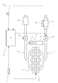
- the block diagram which showed the whole structure of the engine provided with the exhaust-air-treatment system which is one Embodiment of this invention.
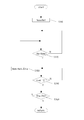
- the flowchart which similarly shows the flow of manual regeneration control.
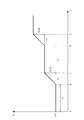
- the graph figure which similarly shows the time-sequential change of manual regeneration control.
- the engine 100 includes an engine body 11 having four cylinders, an intake path 12, an exhaust path 13, an EGR path 14, a regeneration switch 70 as a manual regeneration means, a fuel injection device 80, and an ECU (Engine Control Unit). 50.
- the intake path 12 is connected to the intake manifold of the engine body 11 and includes an air cleaner 25 and an intake throttle 20 on the path.
- the intake throttle 20 is disposed on the downstream side of the intake passage 12 with respect to the air cleaner 25.
- the exhaust path 13 is connected to an exhaust manifold of the engine body 11 and includes an exhaust throttle 30 and a DPF (Diesel Particulate Filter) 35 as a particulate removal filter on the path.
- the exhaust throttle 30 is disposed upstream of the DPF 35 in the exhaust path 13.
- the EGR path 14 is connected to the downstream side of the intake throttle 20 of the intake path 12 and is connected to the upstream side of the exhaust throttle 30 of the exhaust path 13, and an EGR valve 40, an EGR cooler 45, and Are provided.
- the ECU 50 is a control means of the engine 100, and includes an intake throttle 20, an exhaust throttle 30, an EGR valve 40, an engine speed sensor 61, an exhaust gas temperature sensor 62, and a regeneration switch 70 as a manual regeneration means.
- the fuel injection device 80 is connected.
- the ECU 50 performs fuel injection control of the fuel injection device 80 so that the engine speed Ne becomes the engine target speed Nem, and controls the engine speed Ne.
- the engine target speed Nem is set by engine target speed setting means such as an accelerator lever, for example.
- the regeneration switch 70 is arranged as a manual switch in the vicinity of the operation panel of the driver's seat. The operator manually regenerates the DPF 35 by turning on the regeneration switch 70 before performing work on the work vehicle.
- the exhaust gas treatment system 10 includes an ECU 50, an exhaust gas temperature sensor 62, a regeneration switch 70, and a fuel injection device 80.
- Regeneration control is performed in which the exhaust gas temperature The is increased to detoxify and remove PM (Particulate Matter) collected in the DPF 35.
- the exhaust gas processing system 10 of the present embodiment increases the engine speed Ne to increase the exhaust gas temperature The. Is raised to the regeneration temperature Th1 or higher to perform manual regeneration control.
- the ECU 50 performs the following manual regeneration control when the regeneration switch 70 is turned on and a manual regeneration signal is received.
- step S110 the ECU 50 controls the engine speed Ne with the engine target speed Nem as a first set value Ne1 that is arbitrarily set in advance.
- the first set value Ne1 is set as the low idle speed of the engine 100.
- step S120 the ECU 50 confirms whether the engine speed Ne has converged to the engine target speed Nem. If the engine speed Ne has converged to the engine target speed Nem, the ECU 50 proceeds to step S130.
- the convergence to the engine target speed Nem means a situation where the engine speed Ne is within a predetermined speed range including the engine target speed Nem for a predetermined time.
- step S130 the ECU 50 confirms whether the exhaust temperature monitoring time t2 has elapsed after the engine speed Ne has converged to the engine target speed Nem. If the exhaust temperature monitoring time t2 has elapsed, the ECU 50 proceeds to step S140. Migrate to The exhaust temperature monitoring time t2 is arbitrarily set in advance and stored in the ECU 50, and is set to a time sufficiently longer than the time (t1 in FIG. 3) in which the engine speed Ne described later increases by a predetermined speed ⁇ Ne. .
- step S140 the ECU 50 confirms whether the exhaust gas temperature The has reached the regeneration temperature Th1 necessary for regeneration of the DPF 35. If the ECU 50 has not reached the regeneration temperature Th1, the ECU 50 proceeds to step S150 and reaches the regeneration temperature Th1. If it has been reached, the current engine target speed Nem is continued. At this time, the PM collected by the DPF 35 is rendered harmless and removed.
- the regeneration temperature Th1 is stored in advance in the ECU 50, and is a temperature at which PM collected by the DPF 35 can be rendered harmless and removed.
- step S150 the ECU 50 resets the target engine speed Nem from the current value by increasing the first set value Ne1 by a predetermined speed ⁇ Ne, and then proceeds to step S120 again.
- the predetermined rotational speed ⁇ Ne is arbitrarily set in advance and stored in the ECU 50.
- FIG. 3 shows a time-series change in the engine speed Ne.
- the behavior of the engine speed Ne will be described according to a time series (sequentially elapsed time points AE).
- the target engine speed Nem is set to the first set value Ne1.
- the engine speed Ne is controlled so as to converge to the first set value Ne1.
- the exhaust gas temperature monitoring time t2 has elapsed, and the exhaust gas temperature The has not reached the regeneration temperature Th1, so the engine target speed Nem is currently From the first set value Ne1, which is a value of, is reset so as to increase by a predetermined rotational speed ⁇ Ne.
- the engine speed Ne is controlled so as to converge to the reset engine target speed Nem (Ne1 + ⁇ Ne).
- the exhaust gas processing system 10 is configured to exhaust the exhaust gas within a predetermined time even after the engine speed Ne has converged to the first set value Ne1 that is the engine target speed Nem after the start of the manual regeneration control. If the temperature The does not reach the regeneration temperature Th1 of the DPF 35, the engine target rotational speed Nem is increased by a predetermined rotational speed from the first set value Ne1, and then set again. Thereafter, the engine target Ne is reset.
- the engine target rotational speed Nem is set to the current engine target rotational speed Nem (Ne1 + ⁇ Ne). From the above, the setting is repeated by increasing the predetermined number of rotations ⁇ Ne.
- the exhaust gas temperature monitoring time t2 elapses for the engine target rotational speed Nem. Every time, the target engine speed Nem (Ne1 + ⁇ Ne), the engine target engine speed Nem (Ne1 + 2 ⁇ Ne), the engine target engine speed Nem (Ne1 + 3 ⁇ Ne), and the engine target engine speed Nem (Ne1 + 4 ⁇ Ne) are incremented step by step.
- the exhaust gas temperature The is raised to reach the regeneration temperature Th1. Therefore, it is possible to suppress an excessive increase in the engine speed Ne while ensuring the exhaust gas temperature The necessary for regeneration of the DPF 35. As a result, wasteful fuel consumption can be reduced.
- the present invention can be used in an engine exhaust gas treatment system that performs manual regeneration control for regenerating a particulate removal filter by increasing the engine speed.
Landscapes
- Engineering & Computer Science (AREA)
- Chemical & Material Sciences (AREA)
- Combustion & Propulsion (AREA)
- Mechanical Engineering (AREA)
- General Engineering & Computer Science (AREA)
- Processes For Solid Components From Exhaust (AREA)
- Electrical Control Of Air Or Fuel Supplied To Internal-Combustion Engine (AREA)
- Combined Controls Of Internal Combustion Engines (AREA)
Abstract
エンジン回転数を上昇させてパティキュレート除去フィルタを再生する手動再生制御において、パティキュレート除去フィルタの再生に必要な排気ガス温度を確保しながら、エンジン回転数の上昇を抑えることができるようにする。手動再生スイッチ70からの再生指示信号を受けたときにエンジン目標回転数Nemを第1設定値Ne1に設定するエンジン100の排気ガス後処理システム10において、エンジン回転数Neがエンジン目標回転数Nemである前記第1設定値Ne1を含む所定のエンジン回転数の範囲内に所定時間収まった後であっても所定時間内に排気ガス温度Theが前記フィルタの再生温度Th1に達しない場合は、エンジン目標回転数Nemを前記第1設定値Ne1から所定回転数だけ増加させて設定し直すことを繰り返す。
Description
本発明は、エンジンの排気ガス処理システムに関する。
従来、ディーゼルエンジンの排気ガスに含まれるPM(Particulate matter)をDPF(Diesel Particulate Filter)と称されるパティキュレート除去フィルタで減少させる技術は公知となっている。
排気ガス温度がDPFの再生温度以上に高い場合、DPFに捕集したPMを無害化させて除去できる。一方、排気ガス温度がDPFの再生温度よりも低い場合、DPFに捕集したPMを無害化させて除去できない。そこで、この場合には、DPFの再生制御として、EGRや燃料過多の排気ガスを用いて排気ガス温度を定期的に再生温度以上にする制御を行って、DPFに捕集したPMを無害化して取り除く必要がある。
特開2004-183506号公報には、排気ガスのDPFを手動再生制御するときにエンジンを所定回転数まで上昇させて、排気ガス温度を再生温度以上にする構成が開示されている。手動再生制御とは、作業者による何らかの手動操作に基づいて再生制御が行われることをいう。
しかし、前記特開2004-183506号公報に記載の構成は、DPFの手動再生制御を行うときには、常に、エンジン回転数を所定回転数まで上昇させるため、それまでの運転で排気ガス温度がDPFの再生温度に近い状態のときには、エンジン回転数が無駄に上昇して、余分な燃料を消費することになる。
本発明は、エンジン回転数を上昇させてパティキュレート除去フィルタを再生する手動再生制御において、パティキュレート除去フィルタの再生に必要な排気ガス温度を確保しながら、エンジン回転数の上昇を抑えることができるエンジンの排気処理システムを提供することを課題とする。
本発明のエンジンの排気ガス処理システムは、排気経路に排気ガスのパティキュレートを除去するフィルタを設け、該フィルタの上流に排気ガス温度を検出する排気ガス温度センサを設け、該フィルタの再生を指示する手動再生手段を設け、該手動再生手段からの再生指示信号を受けたときにエンジンの目標回転数を第1設定値に設定するエンジンの排気ガス処理システムにおいて、エンジン回転数が目標回転数である前記第一設定値を含む所定のエンジン回転数の範囲内に所定時間収まった後であっても所定時間内に排気ガス温度が前記フィルタの再生温度に達しない場合は、目標回転数を前記第1設定値から所定回転数だけ増加させて設定し直し、その後、エンジン回転数が設定し直した目標回転数を含む所定のエンジン回転数の範囲内に所定時間収まった後であっても所定時間内に排気ガス温度が前記フィルタの再生温度に達しない場合は、目標回転数を現在の目標回転数から所定回転数だけ増加させて設定し直すことを繰り返すものである。
本発明のエンジンの排気ガス処理システムによれば、エンジン回転数を上昇させてパティキュレート除去フィルタを再生する手動再生制御において、パティキュレート除去フィルタの再生に必要な排気ガス温度を確保しながら、エンジン回転数の上昇を抑えることができる。
図1を用いて、本発明の一実施形態である排気ガス処理システム10を備えるエンジン100について説明する。
エンジン100は、4気筒を備えるエンジン本体11と、吸気経路12と、排気経路13と、EGR経路14と、手動再生手段としての再生スイッチ70と、燃料噴射装置80と、ECU(Engine Control Unit)50と、を具備している。
エンジン100は、4気筒を備えるエンジン本体11と、吸気経路12と、排気経路13と、EGR経路14と、手動再生手段としての再生スイッチ70と、燃料噴射装置80と、ECU(Engine Control Unit)50と、を具備している。
吸気経路12は、エンジン本体11の吸気マニホールドに接続され、その経路上にエアクリーナ25と、吸気スロットル20と、を具備している。吸気スロットル20は、エアクリーナ25よりも吸気経路12の下流側に配置されている。
排気経路13は、エンジン本体11の排気マニホールドに接続され、その経路上に排気スロットル30と、パティキュレート除去フィルタとしてのDPF(Diesel Particulate Filter)35と、を具備している。排気スロットル30は、DPF35よりも排気経路13の上流側に配置されている。
EGR経路14は、吸気経路12の吸気スロットル20よりも下流側と接続されるとともに、排気経路13の排気スロットル30よりも上流側と接続され、その経路上にEGR弁40と、EGRクーラー45と、を具備している。
排気経路13は、エンジン本体11の排気マニホールドに接続され、その経路上に排気スロットル30と、パティキュレート除去フィルタとしてのDPF(Diesel Particulate Filter)35と、を具備している。排気スロットル30は、DPF35よりも排気経路13の上流側に配置されている。
EGR経路14は、吸気経路12の吸気スロットル20よりも下流側と接続されるとともに、排気経路13の排気スロットル30よりも上流側と接続され、その経路上にEGR弁40と、EGRクーラー45と、を具備している。
ECU50は、エンジン100の制御手段であって、吸気スロットル20と、排気スロットル30と、EGR弁40と、エンジン回転数センサ61と、排気ガス温度センサ62と、手動再生手段としての再生スイッチ70と、燃料噴射装置80と、に接続されている。
ECU50は、エンジン回転数Neがエンジン目標回転数Nemとなるように燃料噴射装置80の燃料噴射制御を行い、エンジン回転数Neの制御を行う。エンジン目標回転数Nemは、例えばアクセルレバーなどのエンジン目標回転数設定手段によって設定される。
再生スイッチ70は、例えばエンジン100が作業車両に搭載される場合は、運転席の操作パネルの近傍に手動スイッチとして配置されるものである。作業者は、作業車両で作業を実施する前に、再生スイッチ70をONとして、DPF35を手動再生する。
ECU50は、エンジン回転数Neがエンジン目標回転数Nemとなるように燃料噴射装置80の燃料噴射制御を行い、エンジン回転数Neの制御を行う。エンジン目標回転数Nemは、例えばアクセルレバーなどのエンジン目標回転数設定手段によって設定される。
再生スイッチ70は、例えばエンジン100が作業車両に搭載される場合は、運転席の操作パネルの近傍に手動スイッチとして配置されるものである。作業者は、作業車両で作業を実施する前に、再生スイッチ70をONとして、DPF35を手動再生する。
排気ガス処理システム10は、ECU50と、排気ガス温度センサ62と、再生スイッチ70と、燃料噴射装置80と、から構成され、排気ガス温度がDPF35の再生に必要な再生温度Th1よりも低いときには、排気ガス温度Theを上昇させてDPF35に捕集したPM(Particulate matter)を無害化して取り除く再生制御を行う。
本実施形態の排気ガス処理システム10は、再生スイッチ70によって再生指示信号を受信した場合に、排気ガス温度が再生温度Th1よりも低いときには、エンジン回転数Neを上昇させることで、排気ガス温度Theを再生温度Th1以上に上昇させて手動再生制御を行う。
本実施形態の排気ガス処理システム10は、再生スイッチ70によって再生指示信号を受信した場合に、排気ガス温度が再生温度Th1よりも低いときには、エンジン回転数Neを上昇させることで、排気ガス温度Theを再生温度Th1以上に上昇させて手動再生制御を行う。
図2を用いて、手動再生制御のフローについて説明する。
ECU50は、再生スイッチ70がONとされ、手動再生信号を受信したときには以下の手動再生制御を行う。
まず、ECU50は、ステップS110において、エンジン目標回転数Nemを予め任意に設定された第1設定値Ne1として、エンジン回転数Neを制御する。本実施形態では、第1設定値Ne1をエンジン100のローアイドル回転数としている。
次に、ECU50は、ステップS120において、エンジン回転数Neがエンジン目標回転数Nemに収束したかを確認し、エンジン目標回転数Nemに収束したならば、ステップS130へ移行する。なお、エンジン目標回転数Nemに収束するとは、エンジン回転数Neがエンジン目標回転数Nemを含む所定の回転数範囲に所定時間収まった状況をいう。
ECU50は、再生スイッチ70がONとされ、手動再生信号を受信したときには以下の手動再生制御を行う。
まず、ECU50は、ステップS110において、エンジン目標回転数Nemを予め任意に設定された第1設定値Ne1として、エンジン回転数Neを制御する。本実施形態では、第1設定値Ne1をエンジン100のローアイドル回転数としている。
次に、ECU50は、ステップS120において、エンジン回転数Neがエンジン目標回転数Nemに収束したかを確認し、エンジン目標回転数Nemに収束したならば、ステップS130へ移行する。なお、エンジン目標回転数Nemに収束するとは、エンジン回転数Neがエンジン目標回転数Nemを含む所定の回転数範囲に所定時間収まった状況をいう。
そして、ECU50は、ステップS130において、エンジン回転数Neがエンジン目標回転数Nemに収束してから排気温度監視時間t2が経過したかを確認し、排気温度監視時間t2が経過したならば、ステップS140へ移行する。なお、排気温度監視時間t2は、予め任意に設定されてECU50に記憶されており、後述するエンジン回転数Neが所定回転数ΔNe増加する時間(図3におけるt1)よりも十分に長い時間とする。
ECU50は、ステップS140において、排気ガス温度TheがDPF35の再生に必要な再生温度Th1に到達したかを確認し、再生温度Th1に到達してない場合は、ステップS150へ移行し、再生温度Th1に到達した場合は、現在のエンジン目標回転数Nemを継続する。この際、DPF35に捕集されたPMは、無害化されて取り除かれる。なお、再生温度Th1は、予めECU50に記憶されており、DPF35に捕集したPMを無害化して取り除くことができる温度である。
ECU50は、ステップS150において、エンジン目標回転数Nemを現在の値から第1設定値Ne1から所定回転数ΔNeだけ増加させて設定し直し、再度ステップS120に移行する。なお、所定回転数ΔNeは、予め任意に設定されてECU50に記憶されている。
ECU50は、ステップS150において、エンジン目標回転数Nemを現在の値から第1設定値Ne1から所定回転数ΔNeだけ増加させて設定し直し、再度ステップS120に移行する。なお、所定回転数ΔNeは、予め任意に設定されてECU50に記憶されている。
図3を用いて、手動再生制御によるエンジン回転数Neの変化の一例について説明する。
図3は、エンジン回転数Neの時系列変化を示している。以下では、時系列(順次経過する時点A~E)に従ってエンジン回転数Neの挙動を説明する。
図3は、エンジン回転数Neの時系列変化を示している。以下では、時系列(順次経過する時点A~E)に従ってエンジン回転数Neの挙動を説明する。
手動再生制御の開始直後の時点Aでは、エンジン目標回転数Nemは第1設定値Ne1に設定される。エンジン回転数Neは、この第1設定値Ne1に収束するように制御されている。
時点Bでは、エンジン回転数Neが第1設定値Ne1に収束した後、排気温度監視時間t2が経過し、排気ガス温度Theが再生温度Th1に到達していないため、エンジン目標回転数Nemは現在の値である第1設定値Ne1から所定回転数ΔNeだけ増加するように設定し直される。
時点Cでは、エンジン回転数Neは、設定し直されたエンジン目標回転数Nem(Ne1+ΔNe)に収束するように制御されている。
時点Bでは、エンジン回転数Neが第1設定値Ne1に収束した後、排気温度監視時間t2が経過し、排気ガス温度Theが再生温度Th1に到達していないため、エンジン目標回転数Nemは現在の値である第1設定値Ne1から所定回転数ΔNeだけ増加するように設定し直される。
時点Cでは、エンジン回転数Neは、設定し直されたエンジン目標回転数Nem(Ne1+ΔNe)に収束するように制御されている。
時点Dでは、エンジン回転数Neがエンジン目標回転数Nem(Ne1+ΔNe)に収束した後、排気温度監視時間t2が経過し、排気ガス温度Theが再生温度Th1に到達していないため、エンジン目標回転数Nemは、現在の値であるエンジン目標回転数Nem(Ne1+ΔNe)から更に所定回転数ΔNeだけ増加するように設定し直される。
時点Eでは、エンジン回転数Neは、エンジン目標回転数Nem(Ne1+2ΔNe)に収束するように制御されている。
以降、排気ガス温度Theが再生温度Th1に到達するまで、時点DからEまでと同様の制御が繰り返される。
時点Eでは、エンジン回転数Neは、エンジン目標回転数Nem(Ne1+2ΔNe)に収束するように制御されている。
以降、排気ガス温度Theが再生温度Th1に到達するまで、時点DからEまでと同様の制御が繰り返される。
以上のように、排気ガス処理システム10は、手動再生制御の開始後に、エンジン回転数Neがエンジン目標回転数Nemである第1設定値Ne1に収束した後であっても所定時間内に排気ガス温度TheがDPF35の再生温度Th1に達しない場合は、エンジン目標回転数Nemを第1設定値Ne1から所定回転数だけ増加させて設定し直し、その後、エンジン回転数Neが設定し直したエンジン目標回転数Nem(Ne1+ΔNe)に収束した後であっても所定時間内に排気ガス温度TheがDPF35の再生温度Th1に達しない場合は、エンジン目標回転数Nemを現在のエンジン目標回転数Nem(Ne1+ΔNe)から所定回転数ΔNeだけ増加させて設定し直すことを繰り返す。
つまり、排気ガス処理システム10は、排気ガス温度Theを監視しながら、排気ガス温度Theが再生温度Th1に到達していない場合には、エンジン目標回転数Nemを、排気温度監視時間t2が経過するたびに、エンジン目標回転数Nem(Ne1+ΔNe)、エンジン目標回転数Nem(Ne1+2ΔNe)、エンジン目標回転数Nem(Ne1+3ΔNe)、エンジン目標回転数Nem(Ne1+4ΔNe)のように、所定回転数ΔNeずつ段階的に上昇させて、排気ガス温度Theを上昇させ再生温度Th1に到達させる。
したがって、DPF35の再生に必要な排気ガス温度Theを確保しながら、余分なエンジン回転数Neの上昇を抑制できる。その結果、燃料の無駄な消費を低減することができる。
したがって、DPF35の再生に必要な排気ガス温度Theを確保しながら、余分なエンジン回転数Neの上昇を抑制できる。その結果、燃料の無駄な消費を低減することができる。
本発明は、エンジン回転数を上昇させてパティキュレート除去フィルタを再生する手動再生制御を行うエンジンの排気ガス処理システムに利用可能である。
Claims (1)
- 排気経路に排気ガスのパティキュレートを除去するフィルタを設け、該フィルタの上流に排気ガス温度を検出する排気ガス温度センサを設け、該フィルタの再生を指示する手動再生手段を設け、該手動再生手段からの再生指示信号を受けたときにエンジンの目標回転数を第1設定値に設定するエンジンの排気ガス処理システムにおいて、
エンジン回転数が目標回転数である前記第一設定値を含む所定のエンジン回転数の範囲内に所定時間収まった後であっても所定時間内に排気ガス温度が前記フィルタの再生温度に達しない場合は、目標回転数を前記第1設定値から所定回転数だけ増加させて設定し直し、その後、エンジン回転数が設定し直した目標回転数を含む所定のエンジン回転数の範囲内に所定時間収まった後であっても所定時間内に排気ガス温度が前記フィルタの再生温度に達しない場合は、目標回転数を現在の目標回転数から所定回転数だけ増加させて設定し直すことを繰り返すことを特徴とするエンジンの排気ガス処理システム。
Priority Applications (2)
| Application Number | Priority Date | Filing Date | Title |
|---|---|---|---|
| EP11753147.5A EP2546483B1 (en) | 2010-03-09 | 2011-02-16 | Exhaust gas treatment system for engine |
| US13/583,377 US8801822B2 (en) | 2010-03-09 | 2011-02-16 | Exhaust gas treatment system for engine |
Applications Claiming Priority (2)
| Application Number | Priority Date | Filing Date | Title |
|---|---|---|---|
| JP2010-052004 | 2010-03-09 | ||
| JP2010052004A JP5395709B2 (ja) | 2010-03-09 | 2010-03-09 | エンジンの排気ガス処理システム |
Publications (1)
| Publication Number | Publication Date |
|---|---|
| WO2011111485A1 true WO2011111485A1 (ja) | 2011-09-15 |
Family
ID=44563310
Family Applications (1)
| Application Number | Title | Priority Date | Filing Date |
|---|---|---|---|
| PCT/JP2011/053231 Ceased WO2011111485A1 (ja) | 2010-03-09 | 2011-02-16 | エンジンの排気ガス処理システム |
Country Status (4)
| Country | Link |
|---|---|
| US (1) | US8801822B2 (ja) |
| EP (1) | EP2546483B1 (ja) |
| JP (1) | JP5395709B2 (ja) |
| WO (1) | WO2011111485A1 (ja) |
Families Citing this family (8)
| Publication number | Priority date | Publication date | Assignee | Title |
|---|---|---|---|---|
| JP5235229B2 (ja) * | 2011-07-04 | 2013-07-10 | 株式会社小松製作所 | 粒子状物質除去フィルタの再生制御装置およびその再生制御方法 |
| US9534551B2 (en) | 2011-09-27 | 2017-01-03 | Kubota Corporation | Working machine |
| JP5795951B2 (ja) * | 2011-12-01 | 2015-10-14 | 株式会社クボタ | 作業機 |
| JP5679938B2 (ja) * | 2011-09-27 | 2015-03-04 | 株式会社クボタ | 作業機 |
| JP5871732B2 (ja) * | 2012-06-29 | 2016-03-01 | 株式会社クボタ | 作業機 |
| US20160084184A1 (en) * | 2014-09-19 | 2016-03-24 | Progress Rail Services Corporation | Exhaust system having aftertreatment regeneration cycle control |
| JP6734796B2 (ja) * | 2017-02-24 | 2020-08-05 | 三菱重工業株式会社 | 舶用ディーゼルエンジン並びにエンジン制御装置及び方法 |
| KR102336403B1 (ko) * | 2017-10-25 | 2021-12-08 | 현대자동차주식회사 | 차량용 배기정화장치의 재생방법 |
Citations (3)
| Publication number | Priority date | Publication date | Assignee | Title |
|---|---|---|---|---|
| JP2004183506A (ja) | 2002-11-29 | 2004-07-02 | Mitsubishi Fuso Truck & Bus Corp | 車両の排気浄化装置 |
| JP2009257323A (ja) * | 2008-03-17 | 2009-11-05 | Komatsu Ltd | ディーゼルエンジン微粒子除去フィルターの再生装置および方法 |
| JP2010007562A (ja) * | 2008-06-26 | 2010-01-14 | Hitachi Constr Mach Co Ltd | 建設機械の排ガス浄化システム |
Family Cites Families (9)
| Publication number | Priority date | Publication date | Assignee | Title |
|---|---|---|---|---|
| JP4083453B2 (ja) * | 2002-03-29 | 2008-04-30 | いすゞ自動車株式会社 | NOx浄化システム及びその触媒劣化回復方法 |
| JP3912294B2 (ja) * | 2003-02-19 | 2007-05-09 | トヨタ自動車株式会社 | 内燃機関の排気浄化方法および排気浄化装置 |
| FR2892641B1 (fr) * | 2005-10-27 | 2008-07-11 | Saint Gobain Ct Recherches | Mesure de l'homogeneite de depot des suies dans un filtre a particules et controle de la regeneration dudit filtre |
| FR2896823B1 (fr) * | 2006-01-31 | 2008-03-14 | Saint Gobain Ct Recherches | Filtre catalytique presentant un temps d'amorcage reduit |
| US20080053074A1 (en) * | 2006-08-31 | 2008-03-06 | Caterpillar Inc. | Method and system for particulate filter regeneration |
| US20080163610A1 (en) * | 2007-01-05 | 2008-07-10 | Matthew Thomas Baird | Method and system for regenerating exhaust system filtering and catalyst components using variable high engine idle |
| JP4948385B2 (ja) * | 2007-12-26 | 2012-06-06 | Udトラックス株式会社 | 排気温度制御装置 |
| JP2009167952A (ja) * | 2008-01-18 | 2009-07-30 | Mitsubishi Heavy Ind Ltd | Dpf付き無過給エンジンの排気温度上昇装置 |
| JP5210995B2 (ja) * | 2009-08-20 | 2013-06-12 | 株式会社クボタ | ディーゼルエンジンの排気処理装置 |
-
2010
- 2010-03-09 JP JP2010052004A patent/JP5395709B2/ja active Active
-
2011
- 2011-02-16 EP EP11753147.5A patent/EP2546483B1/en active Active
- 2011-02-16 US US13/583,377 patent/US8801822B2/en active Active
- 2011-02-16 WO PCT/JP2011/053231 patent/WO2011111485A1/ja not_active Ceased
Patent Citations (3)
| Publication number | Priority date | Publication date | Assignee | Title |
|---|---|---|---|---|
| JP2004183506A (ja) | 2002-11-29 | 2004-07-02 | Mitsubishi Fuso Truck & Bus Corp | 車両の排気浄化装置 |
| JP2009257323A (ja) * | 2008-03-17 | 2009-11-05 | Komatsu Ltd | ディーゼルエンジン微粒子除去フィルターの再生装置および方法 |
| JP2010007562A (ja) * | 2008-06-26 | 2010-01-14 | Hitachi Constr Mach Co Ltd | 建設機械の排ガス浄化システム |
Non-Patent Citations (1)
| Title |
|---|
| See also references of EP2546483A4 |
Also Published As
| Publication number | Publication date |
|---|---|
| EP2546483A1 (en) | 2013-01-16 |
| JP2011185178A (ja) | 2011-09-22 |
| JP5395709B2 (ja) | 2014-01-22 |
| EP2546483B1 (en) | 2022-04-13 |
| US20120325093A1 (en) | 2012-12-27 |
| EP2546483A4 (en) | 2016-05-25 |
| US8801822B2 (en) | 2014-08-12 |
Similar Documents
| Publication | Publication Date | Title |
|---|---|---|
| JP5395709B2 (ja) | エンジンの排気ガス処理システム | |
| JP5034536B2 (ja) | 車載内燃機関の排気浄化装置 | |
| EP2469050B1 (en) | Diesel engine | |
| JP2005214178A (ja) | 内燃機関の排気浄化装置 | |
| US20120227379A1 (en) | Filter Cleaning With An Engine Idle Bump | |
| CN108301900A (zh) | 内燃机的排气净化装置和内燃机的排气净化方法 | |
| CN104160123A (zh) | 内燃机的排气净化装置 | |
| JP6436132B2 (ja) | 内燃機関の排気浄化システム | |
| JP5530226B2 (ja) | エンジンの排気ガス処理システム | |
| CA2946484C (en) | Exhaust gas cleaning apparatus for internal combustion engine | |
| WO2017018083A1 (ja) | 内燃機関の制御装置 | |
| US7543446B2 (en) | System for controlling regeneration of exhaust gas aftertreatment components | |
| JP2018123776A (ja) | 内燃機関の排気浄化装置 | |
| KR102072193B1 (ko) | 촉매 미립자 필터를 포함하는 배기 가스 처리 시스템 및 배기 가스 처리 방법 | |
| JP2010249076A (ja) | 内燃機関の排気浄化装置 | |
| JP6345962B2 (ja) | エンジン | |
| JP2016211507A (ja) | エンジンの排気浄化装置 | |
| WO2017130408A1 (ja) | 排気浄化装置 | |
| JP2018087542A (ja) | 内燃機関の排気浄化装置 | |
| JP6617865B2 (ja) | エンジンの排気浄化装置 | |
| CN116658280B (zh) | 控制方法、装置和车辆 | |
| CN110118116A (zh) | 用于排气处理设备的方法和系统 | |
| JP4411942B2 (ja) | 内燃機関の排気浄化装置 | |
| JP2013108473A (ja) | 内燃機関の排気浄化装置 | |
| JP2013108474A (ja) | 内燃機関の排気浄化装置 |
Legal Events
| Date | Code | Title | Description |
|---|---|---|---|
| 121 | Ep: the epo has been informed by wipo that ep was designated in this application |
Ref document number: 11753147 Country of ref document: EP Kind code of ref document: A1 |
|
| WWE | Wipo information: entry into national phase |
Ref document number: 13583377 Country of ref document: US |
|
| NENP | Non-entry into the national phase |
Ref country code: DE |
|
| WWE | Wipo information: entry into national phase |
Ref document number: 2011753147 Country of ref document: EP |