WO2011111584A1 - Dpf故障検出方法及びdpf故障検出装置 - Google Patents
Dpf故障検出方法及びdpf故障検出装置 Download PDFInfo
- Publication number
- WO2011111584A1 WO2011111584A1 PCT/JP2011/054765 JP2011054765W WO2011111584A1 WO 2011111584 A1 WO2011111584 A1 WO 2011111584A1 JP 2011054765 W JP2011054765 W JP 2011054765W WO 2011111584 A1 WO2011111584 A1 WO 2011111584A1
- Authority
- WO
- WIPO (PCT)
- Prior art keywords
- dpf
- amount
- failure detection
- regeneration
- internal combustion
- Prior art date
- Legal status (The legal status is an assumption and is not a legal conclusion. Google has not performed a legal analysis and makes no representation as to the accuracy of the status listed.)
- Ceased
Links
Images


Classifications
-
- F—MECHANICAL ENGINEERING; LIGHTING; HEATING; WEAPONS; BLASTING
- F01—MACHINES OR ENGINES IN GENERAL; ENGINE PLANTS IN GENERAL; STEAM ENGINES
- F01N—GAS-FLOW SILENCERS OR EXHAUST APPARATUS FOR MACHINES OR ENGINES IN GENERAL; GAS-FLOW SILENCERS OR EXHAUST APPARATUS FOR INTERNAL-COMBUSTION ENGINES
- F01N11/00—Monitoring or diagnostic devices for exhaust-gas treatment apparatus
- F01N11/007—Monitoring or diagnostic devices for exhaust-gas treatment apparatus the diagnostic devices measuring oxygen or air concentration downstream of the exhaust apparatus
-
- F—MECHANICAL ENGINEERING; LIGHTING; HEATING; WEAPONS; BLASTING
- F01—MACHINES OR ENGINES IN GENERAL; ENGINE PLANTS IN GENERAL; STEAM ENGINES
- F01N—GAS-FLOW SILENCERS OR EXHAUST APPARATUS FOR MACHINES OR ENGINES IN GENERAL; GAS-FLOW SILENCERS OR EXHAUST APPARATUS FOR INTERNAL-COMBUSTION ENGINES
- F01N11/00—Monitoring or diagnostic devices for exhaust-gas treatment apparatus
- F01N11/002—Monitoring or diagnostic devices for exhaust-gas treatment apparatus the diagnostic devices measuring or estimating temperature or pressure in, or downstream of the exhaust apparatus
-
- F—MECHANICAL ENGINEERING; LIGHTING; HEATING; WEAPONS; BLASTING
- F02—COMBUSTION ENGINES; HOT-GAS OR COMBUSTION-PRODUCT ENGINE PLANTS
- F02D—CONTROLLING COMBUSTION ENGINES
- F02D41/00—Electrical control of supply of combustible mixture or its constituents
- F02D41/02—Circuit arrangements for generating control signals
- F02D41/021—Introducing corrections for particular conditions exterior to the engine
- F02D41/0235—Introducing corrections for particular conditions exterior to the engine in relation with the state of the exhaust gas treating apparatus
- F02D41/027—Introducing corrections for particular conditions exterior to the engine in relation with the state of the exhaust gas treating apparatus to purge or regenerate the exhaust gas treating apparatus
- F02D41/029—Introducing corrections for particular conditions exterior to the engine in relation with the state of the exhaust gas treating apparatus to purge or regenerate the exhaust gas treating apparatus the exhaust gas treating apparatus being a particulate filter
-
- F—MECHANICAL ENGINEERING; LIGHTING; HEATING; WEAPONS; BLASTING
- F02—COMBUSTION ENGINES; HOT-GAS OR COMBUSTION-PRODUCT ENGINE PLANTS
- F02D—CONTROLLING COMBUSTION ENGINES
- F02D41/00—Electrical control of supply of combustible mixture or its constituents
- F02D41/22—Safety or indicating devices for abnormal conditions
-
- F—MECHANICAL ENGINEERING; LIGHTING; HEATING; WEAPONS; BLASTING
- F01—MACHINES OR ENGINES IN GENERAL; ENGINE PLANTS IN GENERAL; STEAM ENGINES
- F01N—GAS-FLOW SILENCERS OR EXHAUST APPARATUS FOR MACHINES OR ENGINES IN GENERAL; GAS-FLOW SILENCERS OR EXHAUST APPARATUS FOR INTERNAL-COMBUSTION ENGINES
- F01N2550/00—Monitoring or diagnosing the deterioration of exhaust systems
- F01N2550/04—Filtering activity of particulate filters
-
- F—MECHANICAL ENGINEERING; LIGHTING; HEATING; WEAPONS; BLASTING
- F01—MACHINES OR ENGINES IN GENERAL; ENGINE PLANTS IN GENERAL; STEAM ENGINES
- F01N—GAS-FLOW SILENCERS OR EXHAUST APPARATUS FOR MACHINES OR ENGINES IN GENERAL; GAS-FLOW SILENCERS OR EXHAUST APPARATUS FOR INTERNAL-COMBUSTION ENGINES
- F01N2560/00—Exhaust systems with means for detecting or measuring exhaust gas components or characteristics
- F01N2560/12—Other sensor principles, e.g. using electro conductivity of substrate or radio frequency
-
- F—MECHANICAL ENGINEERING; LIGHTING; HEATING; WEAPONS; BLASTING
- F02—COMBUSTION ENGINES; HOT-GAS OR COMBUSTION-PRODUCT ENGINE PLANTS
- F02D—CONTROLLING COMBUSTION ENGINES
- F02D2200/00—Input parameters for engine control
- F02D2200/02—Input parameters for engine control the parameters being related to the engine
- F02D2200/08—Exhaust gas treatment apparatus parameters
- F02D2200/0812—Particle filter loading
-
- Y—GENERAL TAGGING OF NEW TECHNOLOGICAL DEVELOPMENTS; GENERAL TAGGING OF CROSS-SECTIONAL TECHNOLOGIES SPANNING OVER SEVERAL SECTIONS OF THE IPC; TECHNICAL SUBJECTS COVERED BY FORMER USPC CROSS-REFERENCE ART COLLECTIONS [XRACs] AND DIGESTS
- Y02—TECHNOLOGIES OR APPLICATIONS FOR MITIGATION OR ADAPTATION AGAINST CLIMATE CHANGE
- Y02T—CLIMATE CHANGE MITIGATION TECHNOLOGIES RELATED TO TRANSPORTATION
- Y02T10/00—Road transport of goods or passengers
- Y02T10/10—Internal combustion engine [ICE] based vehicles
- Y02T10/40—Engine management systems
Definitions
- the present invention relates to a DPF failure detection method and a DPF failure detection device that collect PM in exhaust gas of an internal combustion engine, and is realized with a simple configuration and detects a failure at a low cost.
- the present invention relates to a failure detection apparatus.
- a diesel particulate filter (hereinafter referred to as DPF) is installed in the exhaust pipe that guides the exhaust gas from the internal combustion engine to the atmosphere. That is, particulate matter (Particulate Matter; hereinafter referred to as PM) is collected.
- the DPF is a filter mainly made of ceramic and having a large number of honeycomb pores (or square pores). In the DPF, PM is collected by adhering to the surface of the honeycomb pores serving as exhaust gas passages.
- the PM sensor of Patent Document 1 is a fixed facility used for research and development of an internal combustion engine, and has a problem and is not suitable for being applied to a vehicle.
- an in-vehicle DPF failure detection device is required to be small, but the PM sensor disclosed in Patent Document 1 uses a high voltage of 2000 to 7000 V, so the device becomes very large and heavy. The cost is also high.
- an object of the present invention is to provide a DPF failure detection method and a DPF failure detection device that solves the above-described problems, is realized with a simple configuration, and detects a failure at low cost.
- a DPF failure detection method of the present invention is a failure detection method for detecting a failure of a diesel particulate filter (hereinafter referred to as DPF) inserted in an exhaust pipe that guides exhaust gas from an internal combustion engine to the atmosphere.
- DPF diesel particulate filter
- Capacitive PM sensor comprising two electrodes arranged on the DPF by calculating the amount of particulate matter (hereinafter referred to as PM) deposited on the DPF from the operating state of the internal combustion engine.
- the amount of PM deposited on the DPF (hereinafter, the actual deposition amount) is measured by the capacitance of the DPF, and when the deviation of the actual deposition amount from the theoretical deposition amount exceeds an allowable limit, it is diagnosed that the DPF has failed. To do.
- the DPF failure detection device of the present invention is a DPF failure detection device that detects a failure of a diesel particulate filter (hereinafter referred to as DPF) inserted in an exhaust pipe that guides exhaust gas from the internal combustion engine to the atmosphere.
- Capacitance type comprising a theoretical deposition amount calculation unit for calculating a deposition amount (hereinafter referred to as a theoretical deposition amount) of particulate matter (hereinafter referred to as PM) from the operating state to the DPF, and two electrodes arranged in the DPF A PM sensor, an actual deposition amount measurement unit that measures the PM deposition amount (hereinafter, actual deposition amount) on the DPF by the capacitance of the capacitance type PM sensor, and the theoretical deposition amount calculation unit calculate A failure diagnosing unit for diagnosing that the DPF has failed when the deviation of the actual deposited amount measured by the actual deposited amount measuring unit with respect to the theoretical deposited amount exceeds an allowable limit.
- the theoretical accumulation amount calculation unit includes a PM generation amount calculation unit that calculates a PM generation amount generated by the internal combustion engine, a PM regeneration amount calculation unit that calculates a PM regeneration amount by passive regeneration in the DPF, and a PM generation amount And a subtraction operation unit that is used for calculating the theoretical deposition amount by subtracting the PM regeneration amount.
- the PM generation amount calculation unit calculates a basic PM amount (basic part) generated by the internal combustion engine based on the engine speed, the fuel amount, and the EGR rate, and based on the engine speed, the fuel amount, and the air-fuel ratio,
- the transient PM amount (transient) generated by the internal combustion engine may be calculated, and the PM generation amount may be calculated as the sum of the basic component and the transient component.
- the PM regeneration amount calculation unit calculates the amount of PM (heat regeneration) regenerated by heat in the DPF based on the air-fuel ratio, oxygen amount, and DPF temperature, and generates NO 2 generation amount, exhaust gas temperature, and exhaust gas volume. Based on this, the amount of PM regenerated by the reaction with NO 2 (NO 2 regeneration) may be calculated, and the PM regeneration amount PMr may be calculated as the sum of heat regeneration and NO 2 regeneration.
- the subtraction calculation unit includes a difference unit that obtains a difference between the PM generation amount and the PM regeneration amount, and an accumulation unit that accumulates the difference while the internal combustion engine is operated, and the difference between the PM generation amount and the PM regeneration amount. Is accumulated, the theoretical deposition amount may be obtained, and the theoretical deposition amount may be cleared at the time of the DPF forced regeneration, and a new accumulation may be started.
- the capacitive PM sensor may be one in which one electrode is provided along one side of the DPF and another electrode is provided along the opposite side.
- the capacitive PM sensor may be one in which one cylindrical electrode is provided so as to cover the entire DPF, and another cylindrical electrode is provided at the center of the DPF. .
- the capacitive PM sensor is provided with one cylindrical electrode so as to cover the entire DPF and another electrode in which a plurality of lines are arranged at the center of the DPF. It may be.
- the capacitive PM sensor may be one in which mesh electrodes are provided on the upstream and downstream sides of the DPF.
- the present invention exhibits the following excellent effects.
- FIG. 1 It is a block diagram of the DPF failure detection apparatus which shows one Embodiment of this invention. It is a block diagram which shows the calculation content in the theoretical deposition amount calculating part of the DPF failure detection apparatus of this invention.
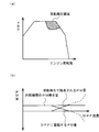
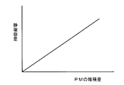
- (A) is a graph of the engine state represented by a two-dimensional plane of engine speed and torque, and (b) is a graph showing the correlation of the PM amount with the DPF temperature. It is a characteristic view of the capacitance type PM sensor used for the DPF failure detection device of the present invention.
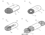
- (A)-(d) is a schematic block diagram of PM sensor used for the DPF failure detection apparatus of this invention.
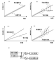
- (A)-(d) is a graph which shows the change of the calculated theoretical deposit amount and the measured actual deposit amount in the DPF failure detection apparatus of this invention, (e) is a block diagram of a failure diagnostic part.
- a DPF failure detection apparatus 1 detects a failure of a diesel particulate filter (hereinafter referred to as DPF) 4 inserted in an exhaust pipe 3 that guides exhaust gas from an internal combustion engine 2 to the atmosphere.
- DPF diesel particulate filter
- the theoretical deposition amount calculation unit 5 that calculates the amount of particulate matter (hereinafter referred to as PM) deposited on the DPF 4 from the operating state of the internal combustion engine 2 is disposed in the DPF 4.
- the capacitance type PM sensor 6 composed of the two electrodes and an actual accumulation amount measuring unit that measures the amount of PM deposited on the DPF 4 (hereinafter, the actual accumulation amount) by the capacitance of the capacitance type PM sensor 6.
- a failure diagnosis unit that diagnoses that the DPF 4 has failed when the difference between the actual deposition amount measured by the actual deposition amount measurement unit 7 and the theoretical deposition amount calculated by the theoretical deposition amount calculation unit 5 exceeds an allowable limit. 8 and be equipped That.
- the internal combustion engine 2 is a diesel engine.
- An intake pipe 9 that supplies air to the internal combustion engine 2 is provided with a MAF sensor 10 that detects an intake air amount, a turbocharger compressor 11, and an intake air cooler 12 in order from the atmosphere side.
- the exhaust pipe 3 is provided with a turbocharger turbine 13 and a DPF 4 in order from the internal combustion engine 2 side.
- an EGR device 14 that circulates exhaust gas to the intake air at an appropriate EGR rate is provided.
- the DPF 4 is a conventionally known one and is made of a ceramic having a large number of honeycomb pores. However, in the present invention, the electrode of the capacitive PM sensor 6 is provided on the DPF 4.
- the theoretical accumulation amount calculation unit 5 includes a PM generation amount calculation unit 21 that calculates a PM generation amount generated by the internal combustion engine 2 and a PM regeneration that calculates a PM regeneration amount by passive regeneration in the DPF 4.
- the PM generation amount calculation unit 21 calculates a basic PM amount (basic part) generated by the internal combustion engine 2 based on the engine speed, the fuel amount, and the EGR rate, and based on the engine speed, the fuel amount, and the air-fuel ratio.
- the transient PM amount (transient amount) generated by the internal combustion engine 2 is calculated, and the PM generation amount PMi is calculated as the sum of the basic amount and the transient amount. For each calculation, an approximate expression obtained by experiment or a map obtained by experiment may be used.
- the PM regeneration amount calculation unit 22 calculates the amount of PM (heat regeneration) regenerated by heat in the DPF 4 based on the air-fuel ratio, the oxygen amount, and the DPF temperature, and calculates the NO 2 generation amount, the exhaust gas temperature, and the exhaust gas volume. Based on the reaction with NO 2 (NOx reduction, PM oxidation), the amount of PM regenerated (NO 2 regeneration) is calculated, and the PM regeneration amount PMr is calculated as the sum of heat regeneration and NO 2 regeneration. It has become. For each calculation, an approximate expression obtained by experiment or a map obtained by experiment may be used.
- the subtraction calculation unit 23 includes a difference unit 24 that takes a difference between the PM generation amount PMi and the PM regeneration amount PMr, and an accumulation unit 25 that accumulates the difference while the internal combustion engine 2 is operated. By accumulating the difference of the PM regeneration amount PMr, the PM amount that should have been deposited on the DPF 4, that is, the theoretical deposition amount PMb is obtained.
- the arithmetic expression is as follows.
- the exhaust gas temperature is raised by the control in which the internal combustion engine 2 performs additional fuel injection after the main injection as necessary, and the PM accumulated in the DPF 4 is burned and removed.
- so-called DPF forced regeneration is performed.
- the theoretical accumulation amount PMb is cleared at the time of forced regeneration of the DPF, and accumulation is newly started.
- PM of the DPF 4 is removed without performing special regeneration control.
- FIG. 3A as a passive regeneration region, in an engine state where the engine speed is high and the torque is large, the temperature of the exhaust gas is remarkably high, so that PM deposited on the DPF 4 burns. This is heat regeneration. Furthermore, since the exhaust gas temperature is high, PM is oxidized by the reaction of NO 2 and PM in the exhaust gas, and NO 2 regeneration occurs.
- the capacitance between two electrodes provided in the DPF 4 changes according to the amount of accumulated PM collected. That is, when the capacitance is C, the dielectric constant is ⁇ , the electrode area is S, and the distance between the electrodes is d,
- the capacitance PM sensor 6 has a characteristic that the capacitance increases in proportion to the amount of PM collected in the DPF 4 increasing.
- the capacitive PM sensor 6a shown in FIG. 5 (a) is provided with one cylindrical piece-shaped electrode 51 along one half of the outer periphery of a columnar DPF 4, and a cylinder along the other half. Another piece-like electrode 52 is provided. As a result, when the two electrodes 51 and 52 face each other with the DPF 4 sandwiched from both sides and PM is collected in the DPF 4, the capacitance changes due to the PM existing between the electrodes 51 and 52.
- one cylindrical electrode 53 is provided so as to cover the entire outer periphery of the columnar DPF 4, and another cylinder-shaped electrode 53 is provided at the center of the DPF 4.
- An electrode 54 is provided.
- one cylindrical electrode 55 is provided so as to cover the entire outer periphery of the columnar DPF 4, and a plurality of lines are formed in the center of the DPF 4 in a cylindrical shape.
- Another electrode 56 arranged in this manner is provided.
- the capacitive PM sensor 6d shown in FIG. 5 (d) has two mesh-like electrodes 57 and 58 provided upstream and downstream of the cylindrical DPF 4, respectively.
- the actual deposition amount measuring unit 7 has a measurement map set based on the characteristics of FIG. 4, detects the capacitance of the capacitive PM sensor 6, and refers to the measurement map with this capacitance. The amount of PM deposition is measured.
- the actual deposition amount measurement unit 7 uses a variable capacitor whose capacitance can be controlled within an appropriate capacitance range, and sweeps the capacitance of the variable capacitor within the range, while The electrical balance between the PM sensor 6 and the variable capacitor is detected, and when the balance is achieved, the capacitance control value of the variable capacitor is read as the capacitance of the capacitance PM sensor 6.
- the failure diagnosis unit 8 obtains a difference between the theoretical deposition amount calculated by the theoretical deposition amount calculation unit 5 and the actual deposition amount measured by the actual deposition amount measurement unit 7, and the DPF 4 has failed when the difference exceeds an allowable limit. Are diagnosed. Specifically, the failure diagnosis unit 8 calculates the difference between the theoretical deposition amount and the actual deposition amount when the actual deposition amount is smaller than the theoretical deposition amount. The difference between the increase rate of the amount and the increase rate of the actual deposition amount is calculated, and when this difference in speed is greater than or equal to a predetermined value, it is diagnosed that the DPF 4 has failed.
- the failure diagnosis unit 8 calculates a difference between the actual deposition amount and the theoretical deposition amount when the actual deposition amount is larger than the theoretical deposition amount.
- the difference between the speed and the increase speed of the theoretical deposition amount is calculated, and when this speed difference is greater than or equal to a predetermined value, it can be diagnosed that an engine failure has occurred in which a large amount of PM is discharged.
- the theoretical accumulation amount calculation unit 5, the actual accumulation amount measurement unit 7, and the failure diagnosis unit 8 are preferably realized by a digital circuit that operates by a program, and is an electronic control unit (ECU) that controls fuel injection, a transmission, and the like of a vehicle ) Is preferably incorporated.
- ECU electronice control unit
- the theoretical deposition amount increases with time. However, for the sake of simplicity, the engine state is assumed to be constant, and the theoretical deposition amount increases linearly. On the other hand, if the DPF 4 is healthy, the actual deposition amount increases in exactly the same way as the theoretical deposition amount. In the figure, the theoretical deposition amount is shifted for distinction, and the actual deposition amount and the theoretical deposition amount actually overlap.
- the failure diagnosis unit 8 diagnoses that the DPF 4 has failed.
- the failure diagnosis unit 8 may diagnose that the DPF 4 has failed when the increase speed difference is equal to or greater than a predetermined value.
- the failure diagnosis unit 8 can diagnose that the DPF 4 has failed when the difference is equal to or greater than the predetermined value or the increase speed difference is equal to or greater than the predetermined value.
- the failure diagnosis unit 8 can diagnose that a failure that causes a large amount of PM in the internal combustion engine 2 has occurred.
- the failure diagnosis unit 8 when the actual deposition amount is smaller than the theoretical deposition amount, if the difference between the theoretical deposition amount and the actual deposition amount is equal to or greater than a predetermined value, the DPF 4 has failed.
- the actual deposition amount is larger than the theoretical deposition amount and the difference between the actual deposition amount and the theoretical deposition amount is equal to or greater than a predetermined value, it is diagnosed that the internal combustion engine 2 has failed.
- the result of diagnosing that the DPF 4 has failed in the failure diagnosing unit 8 is notified to the driver by audiovisual means, and an immediate countermeasure is possible.
- the DPF failure detection method (or DPF failure detection apparatus 1) of the present invention
- the theoretical deposition amount from the operating state of the internal combustion engine 2 to the DPF 4 is calculated, and the capacitance PM sensor 6 Since the actual deposition amount on the DPF 4 is measured by the capacitance, and the deviation of the actual deposition amount from the theoretical deposition amount exceeds the allowable limit, it is diagnosed that the DPF 4 has failed.
- failure detection can be realized at a low cost with a simple configuration.
- the capacitive PM sensor 6 does not require a high voltage, has a very simple configuration, does not require a safety measure for electrical insulation, and does not require a countermeasure for radiation noise. It becomes.
Landscapes
- Engineering & Computer Science (AREA)
- Chemical & Material Sciences (AREA)
- Combustion & Propulsion (AREA)
- Mechanical Engineering (AREA)
- General Engineering & Computer Science (AREA)
- Chemical Kinetics & Catalysis (AREA)
- Processes For Solid Components From Exhaust (AREA)
Abstract
簡素な構成で実現され、低コストに故障が検出されるDPF故障検出方法及びDPF故障検出装置を提供する。 内燃機関2の運転状態からDPF4へのPMの理論堆積量を演算し、静電容量型PMセンサ6の静電容量によってDPF4へのPMの実堆積量を測定し、理論堆積量に対して実堆積量の乖離が許容限界を超えたとき、DPF4が故障したと診断する。
Description
本発明は、内燃機関の排気ガス中のPMを捕集するDPFの故障検出方法及びDPF故障検出装置に係り、簡素な構成で実現され、低コストに故障が検出されるDPF故障検出方法及びDPF故障検出装置に関する。
ディーゼルエンジンなどの内燃機関が搭載された車両では、内燃機関から大気まで排気ガスを導く排気管にディーゼルパティキュレートフィルタ(Diesel Particulate Filter;以下、DPFという)が設置され、排気ガスに含まれる煤、すなわち粒子状物質(Particulate Matter;以下、PMという)が捕集される。DPFは、主としてセラミックからなり、ハニカム細孔(又は四角い細孔)を多数有するフィルタである。DPFでは、排気ガスの通路となるハニカム細孔の表面にPMが付着することでPMが捕集される。
しかし、DPFに損傷、割れなどの故障が発生すると、PMの捕集が不十分になり、DPFの下流にPMが流出し、PMが大気に放出されるおそれがある。これが防止されるには、DPFの故障が検出され、早急に対処されるようになることが望まれる。これに鑑み、米国では、OBD(On-board Diagnosis)法規により、DPF故障検出モニタが車両に搭載されることが義務化される運びとなった。
従来の技術では、DPFの前後の圧力差を測定する差圧センサが設置され、差圧センサの出力値が、DPFが正常な状態の出力範囲を大きく下回ったときに、DPFが故障であると判定されるのが主流である。しかしながら、差圧センサが使用された方法では、検出精度に問題があり今後強化される規制に対応できなくなる可能性がある。そこで、対応策として排気ガス中のPM量を検出するPMセンサとして、特許文献1のものが知られている。
しかしながら、特許文献1のPMセンサは、内燃機関の研究開発に使用される固定設備であって、車載に応用されるには問題があり、不向きであると考えられる。
例えば、車載であるDPF故障検出装置は小型であることが要求されるが、特許文献1のPMセンサは、2000~7000Vという高電圧が使用されるため、装置が非常に大掛かりとなり、重量も重く、コストも高くなる。
また、特許文献1のPMセンサは、高電圧が使用されるため、電気的絶縁がなされる安全対策が必要になり、それによってコストも高くなる。さらに、高電圧の使用によって輻射ノイズが発生することが懸念される。
そこで、本発明の目的は、上記課題を解決し、簡素な構成で実現され、低コストに故障が検出されるDPF故障検出方法及びDPF故障検出装置を提供することにある。
上記目的を達成するために本発明のDPF故障検出方法は、内燃機関から大気まで排気ガスを導く排気管に挿入されたディーゼルパティキュレートフィルタ(以下、DPF)の故障を検出する故障検出方法において、前記内燃機関の運転状態から前記DPFへの粒子状物質(以下、PM)の堆積量(以下、理論堆積量)を演算し、前記DPFに配置された2つの電極からなる静電容量型PMセンサの静電容量によって前記DPFへのPMの堆積量(以下、実堆積量)を測定し、理論堆積量に対して実堆積量の乖離が許容限界を超えたとき、前記DPFが故障したと診断するものである。
また、本発明のDPF故障検出装置は、内燃機関から大気まで排気ガスを導く排気管に挿入されたディーゼルパティキュレートフィルタ(以下、DPF)の故障を検出するDPF故障検出装置において、前記内燃機関の運転状態から前記DPFへの粒子状物質(以下、PM)の堆積量(以下、理論堆積量)を演算する理論堆積量演算部と、前記DPFに配置された2つの電極からなる静電容量型PMセンサと、前記静電容量型PMセンサの静電容量によって前記DPFへのPMの堆積量(以下、実堆積量)を測定する実堆積量測定部と、前記理論堆積量演算部が演算した理論堆積量に対して前記実堆積量測定部が測定した実堆積量の乖離が許容限界を超えたとき、前記DPFが故障したと診断する故障診断部とを備えたものである。
前記理論堆積量演算部は、前記内燃機関が発生するPM発生量を演算するPM発生量演算部と、前記DPFでの受動再生によるPM再生量を演算するPM再生量演算部と、PM発生量からPM再生量を差し引いて理論堆積量の演算に用いる差引演算部とを備えてもよい。
前記PM発生量演算部は、エンジン回転数と燃料量とEGR率に基づき前記内燃機関が発生する基本的なPM量(基本分)を演算し、エンジン回転数と燃料量と空燃比に基づき前記内燃機関が発生する過渡的なPM量(過渡分)を演算し、基本分と過渡分の和としてPM発生量を演算してもよい。
前記PM再生量演算部は、空燃比と酸素量とDPF温度に基づき前記DPFにおいて熱によって再生されるPM量(熱再生分)を演算し、NO2発生量と排気ガス温度と排気ガス体積に基づきNO2との反応によって再生されるPM量(NO2再生分)を演算し、熱再生分とNO2再生分の和としてPM再生量PMrを演算してもよい。
前記差引演算部は、PM発生量とPM再生量の差分をとる差分部と、前記内燃機関が運転されている間、差分を累積する累積部とからなり、PM発生量とPM再生量の差分が累積されることにより、理論堆積量が求められ、DPF強制再生時に理論堆積量がクリアされて新たに累積が開始されてもよい。
前記静電容量型PMセンサは、前記DPFの片側に沿わせて1つの電極が設けられ、反対側に沿わせてもう1つの電極が設けられたものであってもよい。
前記静電容量型PMセンサは、前記DPFの全体を覆うように筒状の1つの電極が設けられ、前記DPFの中心部に筒状のもう1つの電極が設けられたものであってもよい。
前記静電容量型PMセンサは、前記DPFの全体を覆うように筒状の1つの電極が設けられ、前記DPFの中心部に線が複数本配置されてなるもう1つの電極が設けられたものであってもよい。
前記静電容量型PMセンサは、前記DPFの上流と下流それぞれにメッシュ状の電極が設けられたものであってもよい。
本発明は次の如き優れた効果を発揮する。
(1)簡素な構成で実現される。
(2)低コストに故障が検出される。
以下、本発明の一実施形態を添付図面に基づいて詳述する。
図1に示されるように、本発明に係るDPF故障検出装置1は、内燃機関2から大気まで排気ガスを導く排気管3に挿入されたディーゼルパティキュレートフィルタ(以下、DPF)4の故障を検出するDPF故障検出装置1において、内燃機関2の運転状態からDPF4への粒子状物質(以下、PM)の堆積量(以下、理論堆積量)を演算する理論堆積量演算部5と、DPF4に配置された2つの電極からなる静電容量型PMセンサ6と、静電容量型PMセンサ6の静電容量によってDPF4へのPMの堆積量(以下、実堆積量)を測定する実堆積量測定部7と、理論堆積量演算部5が演算した理論堆積量に対して実堆積量測定部7が測定した実堆積量の乖離が許容限界を超えたとき、DPF4が故障したと診断する故障診断部8とを備える。
内燃機関2は、ディーゼルエンジンである。内燃機関2に空気を供給する吸気管9には、大気側から順に、吸入空気量を検出するMAFセンサ10、ターボチャージャのコンプレッサ11、吸入空気冷却器12が設けられる。排気管3には、内燃機関2側から順にターボチャージャのタービン13、DPF4が設けられる。内燃機関2の排気マニホールドと吸気マニホールドとの間には排気ガスを適宜なEGR率で吸気に循環させるEGR装置14が設けられる。
DPF4は、従来公知のもので、多数のハニカム細孔を有するセラミックから構成される。ただし、本発明では、DPF4に静電容量型PMセンサ6の電極が設けられる。
理論堆積量演算部5は、図2に示されるように、内燃機関2が発生するPM発生量を演算するPM発生量演算部21と、DPF4での受動再生によるPM再生量を演算するPM再生量演算部22と、PM発生量からPM再生量を差し引いて理論堆積量の演算に用いる差引演算部23とを備える。
PM発生量演算部21は、エンジン回転数と燃料量とEGR率に基づき、内燃機関2が発生する基本的なPM量(基本分)を演算し、エンジン回転数と燃料量と空燃比に基づき内燃機関2が発生する過渡的なPM量(過渡分)を演算し、基本分と過渡分の和として、PM発生量PMiを演算するようになっている。各演算には、実験により求めた近似式あるいは実験により求められたマップが用いられるとよい。
PM再生量演算部22は、空燃比と酸素量とDPF温度に基づき、DPF4において熱によって再生されるPM量(熱再生分)を演算し、NO2発生量と排気ガス温度と排気ガス体積に基づき、NO2との反応(NOx還元、PM酸化)によって再生されるPM量(NO2再生分)を演算し、熱再生分とNO2再生分の和として、PM再生量PMrを演算するようになっている。各演算には、実験により求められた近似式あるいは実験により求められたマップが用いられるとよい。
差引演算部23は、PM発生量PMiとPM再生量PMrの差分をとる差分部24と、内燃機関2が運転されている間、差分を累積する累積部25とからなり、PM発生量PMiとPM再生量PMrの差分が累積されることにより、DPF4に堆積されているはずのPM量、すなわち理論堆積量PMbが求められる。演算式は、次の通りである。
なお、DPF4が搭載された車両においては、内燃機関2において必要に応じて主噴射後に追加の燃料噴射が行われる制御によって、排気温度が上昇され、DPF4に堆積したPMが燃焼して除去される、いわゆるDPF強制再生が行われる。前述の演算式は、DPF強制再生時に理論堆積量PMbがクリアされ、新たに累積が開始される。
一方、受動再生は、格別な再生制御を行わないでDPF4のPMが除去されるものである。例えば、図3(a)に受動再生領域として示されるように、エンジン回転数が高く、かつトルクが大きいエンジン状態では、排気ガスの温度が顕著に高いため、DPF4に堆積したPMが燃焼する。これが熱再生である。さらに、排気ガス温度が高いために、排気ガス中でNO2とPMの反応によってPMが酸化されNO2再生が起きる。
図3(b)に示されるように、内燃機関2のPM発生量が一定と仮定したとき、DPF温度が高くなると、受動再生で除去されるPM量が多くなり、これに伴いDPF4に堆積するPM量は少なくなる。このような排気ガスの温度(DPF温度)に起因して再生されるPM量が前述の熱再生分とNO2再生分である。
次に、図1の静電容量型PMセンサ6は、DPF4に設けた2つの電極間の静電容量が捕集されたPMの堆積量に応じて変化するものである。すなわち、静電容量をC、誘電率をε、電極面積をS、電極間距離をdとすると、

の関係が成り立ち、電極間の媒体中にPMが増加して誘電率εが大きくなると、静電容量Cが大きくなるという原理に従う。
これにより、静電容量型PMセンサ6は、図4に示されるように、DPF4に捕集されたPMの堆積量が増えるとそれに比例して静電容量が増える特性を有する。
図5(a)に示した静電容量型PMセンサ6aは、円柱状のDPF4の外周の片側半分に沿わせて円筒片状の1つの電極51が設けられ、反対側半分に沿わせて円筒片状のもう1つの電極52が設けられたものである。これにより、2つの電極51,52がDPF4を両側から挟んで互いに対向し、DPF4にPMが捕集されると、電極51,52間に存在するPMの影響で静電容量が変化する。
図5(b)に示した静電容量型PMセンサ6bは、円柱状のDPF4の外周全体を覆うように円筒状の1つの電極53が設けられ、DPF4の中心部に円筒状のもう1つの電極54が設けられたものである。これにより、2つの電極53,54がDPF4の内外に同心状に配置され、DPF4にPMが捕集されると、電極53,54間に存在するPMの影響で静電容量が変化する。
図5(c)に示した静電容量型PMセンサ6cは、円柱状のDPF4の外周全体を覆うように円筒状の1つの電極55が設けられ、DPF4の中心部に線が円筒状に複数本配置されてなるもう1つの電極56が設けられたものである。
図5(d)に示した静電容量型PMセンサ6dは、円柱状のDPF4の上流と下流それぞれにメッシュ状の2つの電極57,58が設けられたものである。
図1の説明に戻る。
実堆積量測定部7は、図4の特性に基づいて設定された測定マップを有し、静電容量型PMセンサ6の静電容量を検出し、この静電容量で測定マップを参照してPM堆積量を測定するようになっている。例えば、実堆積量測定部7は、適宜な静電容量の範囲内で静電容量を制御可能な可変コンデンサを用い、可変コンデンサの静電容量を前記範囲内で掃引しつつ、静電容量型PMセンサ6と可変コンデンサの電気的平衡を検出し、平衡が取れた時点で、可変コンデンサの静電容量制御値を静電容量型PMセンサ6の静電容量として読み取るようになっている。
故障診断部8は、理論堆積量演算部5が演算した理論堆積量と実堆積量測定部7が測定した実堆積量との乖離を求め、この乖離が許容限界を越えたときDPF4が故障したと診断するものである。具体的には、故障診断部8は、理論堆積量より実堆積量が小さい場合に、理論堆積量と実堆積量との差分を演算し、この差分が所定値以上のとき、あるいは、理論堆積量の増加速度と実堆積量の増加速度の差を演算し、この速度差が所定値以上のとき、DPF4が故障したと診断することになる。
また、故障診断部8は、理論堆積量より実堆積量が大きい場合に、実堆積量と理論堆積量との差分を演算し、この差分が所定値以上のとき、あるいは、実堆積量の増加速度と理論堆積量の増加速度の差を演算し、この速度差が所定値以上のとき、PMが大量に排出されるエンジン故障が発生したと診断することができる。
理論堆積量演算部5、実堆積量測定部7、故障診断部8は、プログラムで動作するデジタル回路で実現されるのが好ましく、車両の燃料噴射、変速機等を制御する電子制御装置(ECU)に組み込まれるのが好ましい。
以下、本発明のDPF故障検出装置1の動作を説明する。
図6(a)に示されるように、理論堆積量は時間の経過と共に増加する。ただし、ここでは簡単のため、エンジン状態が一定であるものとしており、理論堆積量は直線的に増加している。一方、DPF4が健全であるとすると、実堆積量は理論堆積量と全く同じように増加する。なお、図では、区別のため理論堆積量をずらせて描いてあり、実際は実堆積量と理論堆積量が重なり合う。
図6(b)に示されるように、DPF4に故障が発生してDPF4の下流にPMが流出するようになると、実堆積量は増加が鈍る。図示例では、故障発生時点(円内)から実堆積量が全く増加していない。これにより差分(楕円内)が大きくなっていくので、差分が所定値以上になれば、故障診断部8は、DPF4が故障したと診断する。あるいは、故障診断部8は、増加速度差が所定値以上のとき、DPF4が故障したと診断してもよい。
また、図6(c)に示されるように、DPF4にもともと故障が発生しているとき、理論堆積量が一定の増加速度で直線的に増加するのに対し、実堆積量は直線的に増加するものの、増加速度が小さい。この場合でも、故障診断部8は、差分が所定値以上あるいは増加速度差が所定値以上のとき、DPF4が故障したと診断することができる。
図6(d)に示されるように、内燃機関2において、PMが大量に発生するような故障が発生した場合には、実堆積量が理論堆積量よりも大きく増加する。これにより差分(楕円内)が大きくなっていくので、差分が所定値以上になれば、故障診断部8は、内燃機関2にPMが大量に発生するような故障が発生したと診断できる。
故障診断部8では、図6(e)に示されるように、理論堆積量より実堆積量が小さい場合に、理論堆積量と実堆積量との差分が所定値以上であれば、DPF4が故障したと診断され、理論堆積量より実堆積量が大きい場合に、実堆積量と理論堆積量との差分が所定値以上になれば、内燃機関2が故障したと診断される。
故障診断部8においてDPF4が故障したと診断した結果は、視聴覚的手段によって運転者に通知され、早急な対処が可能となる。
以上説明したように、本発明のDPF故障検出方法(またはDPF故障検出装置1)によれば、内燃機関2の運転状態からDPF4への理論堆積量を演算し、静電容量型PMセンサ6の静電容量によってDPF4への実堆積量を測定し、理論堆積量に対して実堆積量の乖離が許容限界を超えたとき、DPF4が故障したと診断するようにしたので、特許文献1のものに比べて簡素な構成で、しかも低コストに故障検出が実現される。すなわち、静電容量型PMセンサ6には高電圧が必要なく、構成が非常に簡素となると共に、電気的絶縁がなされる安全対策が不要であり、輻射ノイズ対策も不要であるから、低コストとなる。
1 DPF故障検出装置
2 内燃機関
3 排気管
4 ディーゼルパティキュレートフィルタ(DPF)
5 理論堆積量演算部
6 静電容量型PMセンサ
7 実堆積量測定部
8 故障診断部
2 内燃機関
3 排気管
4 ディーゼルパティキュレートフィルタ(DPF)
5 理論堆積量演算部
6 静電容量型PMセンサ
7 実堆積量測定部
8 故障診断部
Claims (10)
- 内燃機関から大気まで排気ガスを導く排気管に挿入されたディーゼルパティキュレートフィルタ(以下、DPF)の故障を検出する故障検出方法において、
前記内燃機関の運転状態から前記DPFへの粒子状物質(以下、PM)の堆積量(以下、理論堆積量)を演算し、
前記DPFに配置された2つの電極からなる静電容量型PMセンサの静電容量によって前記DPFへのPMの堆積量(以下、実堆積量)を測定し、
理論堆積量に対して実堆積量の乖離が許容限界を超えたとき、前記DPFが故障したと診断することを特徴とするDPF故障検出方法。 - 内燃機関から大気まで排気ガスを導く排気管に挿入されたディーゼルパティキュレートフィルタ(以下、DPF)の故障を検出するDPF故障検出装置において、
前記内燃機関の運転状態から前記DPFへの粒子状物質(以下、PM)の堆積量(以下、理論堆積量)を演算する理論堆積量演算部と、
前記DPFに配置された2つの電極からなる静電容量型PMセンサと、前記静電容量型PMセンサの静電容量によって前記DPFへのPMの堆積量(以下、実堆積量)を測定する実堆積量測定部と、
前記理論堆積量演算部が演算した理論堆積量に対して前記実堆積量測定部が測定した実堆積量の乖離が許容限界を超えたとき、前記DPFが故障したと診断する故障診断部とを備えたことを特徴とするDPF故障検出装置。 - 前記理論堆積量演算部は、
前記内燃機関が発生するPM発生量を演算するPM発生量演算部と、
前記DPFでの受動再生によるPM再生量を演算するPM再生量演算部と、
PM発生量からPM再生量を差し引いて理論堆積量の演算に用いる差引演算部とを備えることを特徴とする請求項2記載のDPF故障検出装置。 - 前記PM発生量演算部は、
エンジン回転数と燃料量とEGR率に基づき前記内燃機関が発生する基本的なPM量(基本分)を演算し、
エンジン回転数と燃料量と空燃比に基づき前記内燃機関が発生する過渡的なPM量(過渡分)を演算し、
基本分と過渡分の和としてPM発生量を演算することを特徴とする請求項3記載のDPF故障検出装置。 - 前記PM再生量演算部は、
空燃比と酸素量とDPF温度に基づき前記DPFにおいて熱によって再生されるPM量(熱再生分)を演算し、
NO2発生量と排気ガス温度と排気ガス体積に基づきNO2との反応によって再生されるPM量(NO2再生分)を演算し、
熱再生分とNO2再生分の和としてPM再生量PMrを演算することを特徴とする請求項3又は4記載のDPF故障検出装置。 - 前記差引演算部は、
PM発生量とPM再生量の差分をとる差分部と、
前記内燃機関が運転されている間、差分を累積する累積部とからなり、
PM発生量とPM再生量の差分が累積されることにより、理論堆積量が求められ、
DPF強制再生時に理論堆積量がクリアされて新たに累積が開始されることを特徴とする請求項3~5いずれか記載のDPF故障検出装置。 - 前記静電容量型PMセンサは、前記DPFの片側に沿わせて1つの電極が設けられ、反対側に沿わせてもう1つの電極が設けられたものであることを特徴とする請求項2~6いずれか記載のDPF故障検出装置。
- 前記静電容量型PMセンサは、前記DPFの全体を覆うように筒状の1つの電極が設けられ、前記DPFの中心部に筒状のもう1つの電極が設けられたものであることを特徴とする請求項2~6いずれか記載のDPF故障検出装置。
- 前記静電容量型PMセンサは、前記DPFの全体を覆うように筒状の1つの電極が設けられ、前記DPFの中心部に線が複数本配置されてなるもう1つの電極が設けられたものであることを特徴とする請求項2~6いずれか記載のDPF故障検出装置。
- 前記静電容量型PMセンサは、前記DPFの上流と下流それぞれにメッシュ状の電極が設けられたものであることを特徴とする請求項2~6いずれか記載のDPF故障検出装置。
Priority Applications (3)
| Application Number | Priority Date | Filing Date | Title |
|---|---|---|---|
| CN201180013127.1A CN102869860B (zh) | 2010-03-10 | 2011-03-02 | Dpf故障检测方法及dpf故障检测装置 |
| US13/579,122 US8770016B2 (en) | 2010-03-10 | 2011-03-02 | DPF failure detection method and DPF failure detection device |
| EP11753243.2A EP2546484B1 (en) | 2010-03-10 | 2011-03-02 | Dpf failure detection method and dpf failure detection device |
Applications Claiming Priority (2)
| Application Number | Priority Date | Filing Date | Title |
|---|---|---|---|
| JP2010-053426 | 2010-03-10 | ||
| JP2010053426A JP5565005B2 (ja) | 2010-03-10 | 2010-03-10 | Dpf故障検出方法及びdpf故障検出装置 |
Publications (1)
| Publication Number | Publication Date |
|---|---|
| WO2011111584A1 true WO2011111584A1 (ja) | 2011-09-15 |
Family
ID=44563388
Family Applications (1)
| Application Number | Title | Priority Date | Filing Date |
|---|---|---|---|
| PCT/JP2011/054765 Ceased WO2011111584A1 (ja) | 2010-03-10 | 2011-03-02 | Dpf故障検出方法及びdpf故障検出装置 |
Country Status (5)
| Country | Link |
|---|---|
| US (1) | US8770016B2 (ja) |
| EP (1) | EP2546484B1 (ja) |
| JP (1) | JP5565005B2 (ja) |
| CN (1) | CN102869860B (ja) |
| WO (1) | WO2011111584A1 (ja) |
Cited By (3)
| Publication number | Priority date | Publication date | Assignee | Title |
|---|---|---|---|---|
| CN103857886A (zh) * | 2011-11-16 | 2014-06-11 | 三菱重工业株式会社 | Dpf的pm堆积量估算装置 |
| CN104024590A (zh) * | 2012-01-20 | 2014-09-03 | 三菱重工业株式会社 | 发动机的排气净化系统 |
| CN111936575A (zh) * | 2018-03-30 | 2020-11-13 | 太阳油墨制造株式会社 | 固化性树脂组合物、干膜、固化物和电子部件 |
Families Citing this family (22)
| Publication number | Priority date | Publication date | Assignee | Title |
|---|---|---|---|---|
| JP6136298B2 (ja) * | 2013-01-28 | 2017-05-31 | いすゞ自動車株式会社 | 内燃機関の排気浄化装置 |
| JP2014145277A (ja) * | 2013-01-28 | 2014-08-14 | Isuzu Motors Ltd | 内燃機関の排気浄化装置 |
| JP6136351B2 (ja) * | 2013-02-22 | 2017-05-31 | いすゞ自動車株式会社 | 内燃機関の排気浄化装置 |
| JP6197377B2 (ja) * | 2013-06-03 | 2017-09-20 | いすゞ自動車株式会社 | 排気浄化装置 |
| JP2015059478A (ja) * | 2013-09-18 | 2015-03-30 | いすゞ自動車株式会社 | 内燃機関の排気浄化装置 |
| JP2015059477A (ja) * | 2013-09-18 | 2015-03-30 | いすゞ自動車株式会社 | 内燃機関の排気浄化装置 |
| JP2015059476A (ja) * | 2013-09-18 | 2015-03-30 | いすゞ自動車株式会社 | 内燃機関の排気浄化装置 |
| JP2015075007A (ja) * | 2013-10-08 | 2015-04-20 | いすゞ自動車株式会社 | 排気浄化システム |
| US10132218B2 (en) | 2014-04-16 | 2018-11-20 | Continental Automotive Gmbh | Exhaust system for a motor vehicle |
| JP6379837B2 (ja) | 2014-08-11 | 2018-08-29 | いすゞ自動車株式会社 | センサ |
| US9399943B1 (en) | 2015-05-04 | 2016-07-26 | Ford Global Technologies, Llc | System and method for detecting particulate filter leakage |
| KR20160149898A (ko) | 2015-06-19 | 2016-12-28 | 현대자동차주식회사 | 입자상 물질 센서 |
| US9551259B1 (en) * | 2015-08-26 | 2017-01-24 | Ford Global Technologies, Llc | Method and system for diesel particulate filter diagnostics |
| US9645068B2 (en) | 2015-10-13 | 2017-05-09 | Ford Global Technologies, Llc | Method and system for particulate filter leakage detection |
| US9551262B1 (en) * | 2015-10-13 | 2017-01-24 | Ford Global Technologies, Llc | Method and system for particulate filter leakage detection |
| WO2017110581A1 (ja) * | 2015-12-25 | 2017-06-29 | 京セラ株式会社 | 粒子状物質の測定装置用部品 |
| CN108279334A (zh) * | 2017-12-29 | 2018-07-13 | 国网北京市电力公司 | 监测方法及装置、系统 |
| WO2019216901A1 (en) | 2018-05-10 | 2019-11-14 | Volvo Truck Corporation | Method and system for assessing engine faults |
| US11333056B2 (en) | 2019-07-15 | 2022-05-17 | Fca Us Llc | Gasoline particulate filter brick detection techniques |
| CN110751749B (zh) * | 2019-09-18 | 2021-08-20 | 中国第一汽车股份有限公司 | 一种gpf冰堵报警提示方法、系统、装置及存储介质 |
| CN110985166B (zh) * | 2019-12-11 | 2021-03-16 | 潍柴动力股份有限公司 | 一种清灰方法及设备 |
| JP7516886B2 (ja) * | 2020-06-09 | 2024-07-17 | 株式会社リコー | 粉体検知システム、トナー収容装置、及び、画像形成装置 |
Citations (5)
| Publication number | Priority date | Publication date | Assignee | Title |
|---|---|---|---|---|
| JP2002021537A (ja) * | 2000-07-03 | 2002-01-23 | Nissan Diesel Motor Co Ltd | ディーゼルエンジンの排気浄化装置 |
| JP2005344619A (ja) * | 2004-06-03 | 2005-12-15 | Denso Corp | 内燃機関の排気浄化装置 |
| JP2006153716A (ja) | 2004-11-30 | 2006-06-15 | Horiba Ltd | 排気ガス分析装置及びSoot測定方法 |
| JP2007262973A (ja) * | 2006-03-28 | 2007-10-11 | Ngk Insulators Ltd | 微粒子量検出システム |
| JP2008267199A (ja) * | 2007-04-17 | 2008-11-06 | Hino Motors Ltd | 排気浄化装置 |
Family Cites Families (6)
| Publication number | Priority date | Publication date | Assignee | Title |
|---|---|---|---|---|
| US20080048681A1 (en) * | 2004-02-12 | 2008-02-28 | Daimlerchrysler Ag | Device for Determining the State of a Soot Particle Filter |
| US7278304B2 (en) * | 2005-12-06 | 2007-10-09 | Ford Global Technologies Llc | System and method for performing a particulate sensor diagnostic |
| US20080155970A1 (en) * | 2006-12-27 | 2008-07-03 | Detroit Diesel Corporation | Method for verifying the functionality of the components of a diesel particulate filter system |
| DE102008015256A1 (de) * | 2008-03-20 | 2009-10-01 | Continental Automotive Gmbh | Diagnoseverfahren und Diagnosesystem für einen Partikelfilter eines Verbrennungsmotors, insbesondere für einen Rußfilter in einem Dieselkraftfahrzeug |
| US20120297750A1 (en) * | 2011-05-25 | 2012-11-29 | GM Global Technology Operations LLC | Method for monitoring an exhaust particulate filter |
| US9303579B2 (en) * | 2012-08-01 | 2016-04-05 | GM Global Technology Operations LLC | System and method for monitoring a particulate filter in a vehicle exhaust aftertreatment device |
-
2010
- 2010-03-10 JP JP2010053426A patent/JP5565005B2/ja not_active Expired - Fee Related
-
2011
- 2011-03-02 EP EP11753243.2A patent/EP2546484B1/en active Active
- 2011-03-02 US US13/579,122 patent/US8770016B2/en active Active
- 2011-03-02 WO PCT/JP2011/054765 patent/WO2011111584A1/ja not_active Ceased
- 2011-03-02 CN CN201180013127.1A patent/CN102869860B/zh active Active
Patent Citations (5)
| Publication number | Priority date | Publication date | Assignee | Title |
|---|---|---|---|---|
| JP2002021537A (ja) * | 2000-07-03 | 2002-01-23 | Nissan Diesel Motor Co Ltd | ディーゼルエンジンの排気浄化装置 |
| JP2005344619A (ja) * | 2004-06-03 | 2005-12-15 | Denso Corp | 内燃機関の排気浄化装置 |
| JP2006153716A (ja) | 2004-11-30 | 2006-06-15 | Horiba Ltd | 排気ガス分析装置及びSoot測定方法 |
| JP2007262973A (ja) * | 2006-03-28 | 2007-10-11 | Ngk Insulators Ltd | 微粒子量検出システム |
| JP2008267199A (ja) * | 2007-04-17 | 2008-11-06 | Hino Motors Ltd | 排気浄化装置 |
Cited By (6)
| Publication number | Priority date | Publication date | Assignee | Title |
|---|---|---|---|---|
| CN103857886A (zh) * | 2011-11-16 | 2014-06-11 | 三菱重工业株式会社 | Dpf的pm堆积量估算装置 |
| EP2781709A4 (en) * | 2011-11-16 | 2015-07-22 | Mitsubishi Heavy Ind Ltd | DEVICE FOR ESTIMATING THE DPF-PM ACCUMULATION AMOUNT |
| CN103857886B (zh) * | 2011-11-16 | 2016-07-06 | 三菱重工业株式会社 | Dpf的pm堆积量估算装置 |
| CN104024590A (zh) * | 2012-01-20 | 2014-09-03 | 三菱重工业株式会社 | 发动机的排气净化系统 |
| US9724643B2 (en) | 2012-01-20 | 2017-08-08 | Mitsubishi Heavy Industries, Ltd. | Exhaust gas purification system for engine |
| CN111936575A (zh) * | 2018-03-30 | 2020-11-13 | 太阳油墨制造株式会社 | 固化性树脂组合物、干膜、固化物和电子部件 |
Also Published As
| Publication number | Publication date |
|---|---|
| EP2546484B1 (en) | 2017-12-27 |
| JP5565005B2 (ja) | 2014-08-06 |
| CN102869860B (zh) | 2014-12-31 |
| EP2546484A1 (en) | 2013-01-16 |
| US20120318055A1 (en) | 2012-12-20 |
| US8770016B2 (en) | 2014-07-08 |
| JP2011185213A (ja) | 2011-09-22 |
| EP2546484A4 (en) | 2016-08-10 |
| CN102869860A (zh) | 2013-01-09 |
Similar Documents
| Publication | Publication Date | Title |
|---|---|---|
| JP5565005B2 (ja) | Dpf故障検出方法及びdpf故障検出装置 | |
| US10612445B2 (en) | Diagnostic device and sensor | |
| US10041916B2 (en) | Method and device for monitoring gas sensors | |
| CN105089759B (zh) | 用于对排气净化设备的组件的拆除进行诊断的方法和装置 | |
| EP1992800A1 (en) | Integrated DPF loading and failure sensor | |
| US20130090866A1 (en) | Diagnostic method for a soot sensor | |
| CN106536881A (zh) | 颗粒过滤器的故障诊断方法及装置 | |
| CN101855529A (zh) | 传感器合理性诊断 | |
| CN105089761A (zh) | 用于诊断颗粒过滤器的方法和装置 | |
| JP2016156357A (ja) | 排気装置の異常判定システム | |
| JP2004526959A (ja) | センサを監視する方法および装置 | |
| GB2538735B (en) | Variable sensitivity pressure differential detection in a vehicle aftertreatment system | |
| JP5120501B2 (ja) | 内燃機関のフィルタ故障検出装置 | |
| JP2007315275A (ja) | 排気浄化フィルタ故障診断装置及び方法 | |
| US20160237873A1 (en) | Diagnostic device | |
| JP4500359B2 (ja) | 排ガスの後処理装置の存在を診断する方法及び車搭載型診断技術の使用 | |
| JP5540585B2 (ja) | Pmセンサ | |
| Hoepfner et al. | PM sensor based on-board diagnosis of particulate filter efficiency | |
| WO2010143657A1 (ja) | Pmセンサ | |
| JP6365319B2 (ja) | Pmセンサの異常診断装置 | |
| JP2014222021A (ja) | 排気温度センサの異常診断装置 | |
| CN102787887B (zh) | 内燃机控制装置 | |
| JP6287896B2 (ja) | 触媒の劣化診断装置 | |
| CN106460627A (zh) | 用于检测颗粒过滤器的功能能力的方法 | |
| Linke et al. | Concept for Diesel Particulate Filter monitoring based on BOSCH Particulate Matter Sensor (PMS) |
Legal Events
| Date | Code | Title | Description |
|---|---|---|---|
| WWE | Wipo information: entry into national phase |
Ref document number: 201180013127.1 Country of ref document: CN |
|
| 121 | Ep: the epo has been informed by wipo that ep was designated in this application |
Ref document number: 11753243 Country of ref document: EP Kind code of ref document: A1 |
|
| WWE | Wipo information: entry into national phase |
Ref document number: 13579122 Country of ref document: US |
|
| NENP | Non-entry into the national phase |
Ref country code: DE |
|
| WWE | Wipo information: entry into national phase |
Ref document number: 2011753243 Country of ref document: EP |