WO2011111632A1 - 自動車用バルブステムシール - Google Patents
自動車用バルブステムシール Download PDFInfo
- Publication number
- WO2011111632A1 WO2011111632A1 PCT/JP2011/055117 JP2011055117W WO2011111632A1 WO 2011111632 A1 WO2011111632 A1 WO 2011111632A1 JP 2011055117 W JP2011055117 W JP 2011055117W WO 2011111632 A1 WO2011111632 A1 WO 2011111632A1
- Authority
- WO
- WIPO (PCT)
- Prior art keywords
- valve stem
- fluororesin
- fluororubber
- seal
- stem seal
- Prior art date
- Legal status (The legal status is an assumption and is not a legal conclusion. Google has not performed a legal analysis and makes no representation as to the accuracy of the status listed.)
- Ceased
Links
Images


Classifications
-
- F—MECHANICAL ENGINEERING; LIGHTING; HEATING; WEAPONS; BLASTING
- F16—ENGINEERING ELEMENTS AND UNITS; GENERAL MEASURES FOR PRODUCING AND MAINTAINING EFFECTIVE FUNCTIONING OF MACHINES OR INSTALLATIONS; THERMAL INSULATION IN GENERAL
- F16J—PISTONS; CYLINDERS; SEALINGS
- F16J15/00—Sealings
- F16J15/16—Sealings between relatively-moving surfaces
- F16J15/32—Sealings between relatively-moving surfaces with elastic sealings, e.g. O-rings
- F16J15/3284—Sealings between relatively-moving surfaces with elastic sealings, e.g. O-rings characterised by their structure; Selection of materials
-
- F—MECHANICAL ENGINEERING; LIGHTING; HEATING; WEAPONS; BLASTING
- F01—MACHINES OR ENGINES IN GENERAL; ENGINE PLANTS IN GENERAL; STEAM ENGINES
- F01L—CYCLICALLY OPERATING VALVES FOR MACHINES OR ENGINES
- F01L3/00—Lift-valve, i.e. cut-off apparatus with closure members having at least a component of their opening and closing motion perpendicular to the closing faces; Parts or accessories thereof
- F01L3/08—Valves guides; Sealing of valve stem, e.g. sealing by lubricant
-
- F—MECHANICAL ENGINEERING; LIGHTING; HEATING; WEAPONS; BLASTING
- F16—ENGINEERING ELEMENTS AND UNITS; GENERAL MEASURES FOR PRODUCING AND MAINTAINING EFFECTIVE FUNCTIONING OF MACHINES OR INSTALLATIONS; THERMAL INSULATION IN GENERAL
- F16J—PISTONS; CYLINDERS; SEALINGS
- F16J15/00—Sealings
- F16J15/16—Sealings between relatively-moving surfaces
- F16J15/32—Sealings between relatively-moving surfaces with elastic sealings, e.g. O-rings
- F16J15/3268—Mounting of sealing rings
- F16J15/3276—Mounting of sealing rings with additional static sealing between the sealing, or its casing or support, and the surface on which it is mounted
-
- F—MECHANICAL ENGINEERING; LIGHTING; HEATING; WEAPONS; BLASTING
- F01—MACHINES OR ENGINES IN GENERAL; ENGINE PLANTS IN GENERAL; STEAM ENGINES
- F01L—CYCLICALLY OPERATING VALVES FOR MACHINES OR ENGINES
- F01L2301/00—Using particular materials
-
- F—MECHANICAL ENGINEERING; LIGHTING; HEATING; WEAPONS; BLASTING
- F01—MACHINES OR ENGINES IN GENERAL; ENGINE PLANTS IN GENERAL; STEAM ENGINES
- F01L—CYCLICALLY OPERATING VALVES FOR MACHINES OR ENGINES
- F01L2303/00—Manufacturing of components used in valve arrangements
-
- F—MECHANICAL ENGINEERING; LIGHTING; HEATING; WEAPONS; BLASTING
- F01—MACHINES OR ENGINES IN GENERAL; ENGINE PLANTS IN GENERAL; STEAM ENGINES
- F01L—CYCLICALLY OPERATING VALVES FOR MACHINES OR ENGINES
- F01L2820/00—Details on specific features characterising valve gear arrangements
- F01L2820/01—Absolute values
Definitions
- the present invention relates to an automotive valve stem seal.
- valve stem seal In the engine valve of an automobile engine, the amount of engine oil supplied to the sliding surface between the valve stem (valve shaft) and the valve stem guide (valve bearing) is adjusted and the exhaust gas is sealed to seal the exhaust gas. A valve stem seal is used.
- Patent Document 1 for the purpose of reducing the sliding resistance between the seal member and the valve stem, a slide that forms a film layer of a diamond-like hard carbon film on the inner peripheral surface of the seal member fitted on the valve stem is disclosed.
- a partial structure is disclosed.
- Patent Document 2 discloses a valve stem seal having a fluororesin film on a sliding surface on the inner periphery of a seal lip portion.
- Patent Document 3 for the purpose of improving durability and sealing performance, a part or all of the sliding surface of the valve stem oil seal material is blended with thermoplastic fluororesin, fluororubber and low molecular weight fluoropolymer. It is disclosed that it is formed from a lubricating rubber composition.
- valve stem seals for automobiles using fluoro rubber or silicon rubber tend to have better sliding characteristics than those for automotive valve stem seals using acrylic rubber or nitrile rubber. There is a need for further improvement in sliding characteristics.
- JP 2005-180329 A JP-A-9-68011 Japanese Patent Laid-Open No. 6-49438
- An object of the present invention is to provide a valve stem seal for automobiles which has not only sealing performance but also durability and low sliding performance at a very high level.
- the present invention is an automotive valve stem seal that is disposed at the end of a valve stem guide and has an elastic member having a seal lip portion that is slidably in close contact with the valve stem of an engine, and the elastic member includes fluororubber And a fluororesin, and at least the surface of the seal lip portion has a convex portion, and the convex portion is substantially made of a fluororesin contained in the composition.
- the present invention relates to a valve stem seal for automobiles, characterized in that the fluororubber is a polymer containing a polymer unit based on vinylidene fluoride. .
- the automotive valve stem seal of the present invention includes an elastic member having a seal lip portion, and the elastic member is made of a specific composition, and at least the surface of the seal lip portion is substantially made of the specific member. Since it has the convex part which consists of a fluororesin contained in a composition, not only sealing performance but durability and low slidability are combined at a very high level. This effect will be described in detail later.
- FIG. It is sectional drawing of the valve stem seal for motor vehicles of this invention shown in FIG. It is sectional drawing which shows typically the engine which uses the valve stem seal for motor vehicles of this invention. It is sectional drawing which shows the usage aspect of the valve stem seal for motor vehicles of this invention typically, and is an enlarged view of A area
- region shown in FIG. (A) is a perspective view showing the shape of the convex portion of the sealing lip has schematically protrusion 31 in a plane containing the (b) is a straight line perpendicular B 1 and the line B 2 on the surface of the (a)
- FIG. 6C is a cross-sectional view taken along a plane including the straight line C 1 and the straight line C 2 having a distance of 0.15 ⁇ m from the surface of FIG. It is a schematic diagram of the stroke load measurement testing machine used in the Example.
- the valve stem seal for automobiles of the present invention is an automobile valve stem seal provided with an elastic member having a seal lip portion, and the elastic member is made of a composition containing fluororubber and fluororesin, and at least the seal
- the surface of the lip has a convex portion, and the convex portion is substantially made of a fluororesin contained in the composition, and the fluororesin includes a polymer unit based on ethylene and a polymer unit based on tetrafluoroethylene. It is a copolymer, and the fluororubber is a polymer containing polymerized units based on vinylidene fluoride.
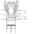
- FIG. 3 is a cross-sectional view schematically showing how the automotive valve stem seal of the present invention is used, and is an enlarged view of region A shown in FIG.
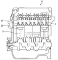
- FIG. 2 is a cross-sectional view schematically showing an engine using the automotive valve stem seal of the present invention
- FIG. 1 is a cross-sectional view of the automotive valve stem seal shown in FIG.
- the automotive valve stem seal 11 of the present invention is provided with a mounting ring 17 so as to be attached to one end (see FIG. 3) of the valve stem guide 13 in the axial direction.
- An elastic member 16 made of a composition containing a fluororesin and fluororubber is bonded to the ring 17.
- the elastic member 16 has a seal lip portion 16 a that is in close contact with the outer peripheral surface of the valve stem 12, and a stationary seal portion 16 b that is in close contact with the outer peripheral surface of the valve stem guide 13.
- a tension force is applied to the valve stem 12 by a spring spring 18 provided around the seal lip portion 16a.
- the elastic member 16 is made of a composition containing fluororesin and fluororubber, and has a convex portion (see FIG. 4) on the surface of the seal lip portion 16a. That is, the valve stem seal 11 has a convex portion at the contact portion with the valve stem 12.
- valve stem seal 11 for motor vehicles has the said convex part, a friction coefficient between the valve stems 12 is small, and it is excellent in a sliding characteristic.
- the said convex part consists of a fluororesin substantially contained in the said composition. Since the fluororesin has a much lower coefficient of friction than fluororubber, the frictional resistance when contacting the valve stem is much lower than that of fluororubber.
- a convex part can be formed by depositing the fluororesin contained in the composition on the surface, for example, by a method as described later. For this reason, there is no clear interface between the convex portion and the main body of the elastic member, and the elastic member 16 having the convex portion is integrally formed. It is possible to more reliably enjoy the effect that it is difficult to be lost or lost.
- the component-derived peak ratio outside the convex part is at least twice the peak ratio derived from the component of the convex part, Preferably it means 3 times or more.
- FIGS. 4A to 4C schematically depict a minute region of the seal lip portion 16a included in the automotive valve stem seal of the present invention.
- a convex portion 31 having a substantially conical shape (cone shape) is formed on the surface of the seal lip portion 16a.
- the height of the convex portion 31 refers to the height of a portion protruding from the surface of the seal lip portion main body (see H in FIG. 4B).
- the diameter of the convex portion 31 means that the convex portion 31 has a predetermined height from the surface of the seal lip portion main body (in this application, 0.15 ⁇ m / see FIG.
- a minimum rectangle inscribed in the closed curve forming the outer edge of the cross section is assumed, and the long side L1 and the short side of this rectangle are assumed.
- the shape of the convex portion preferably has an average height of 0.5 to 5.0 ⁇ m. This is because when the average height is within this range, the seal lip portion is particularly excellent in low slidability.
- a more preferable average height is 0.5 to 3.0 ⁇ m. More preferably, it is 0.5 to 2.0 ⁇ m.
- the average diameter of the convex portions is preferably 5 to 20 ⁇ m. More preferably, it is 5 to 15 ⁇ m. This is because when the average diameter of the convex portions is within this range, the seal lip portion is particularly excellent in low slidability.
- region which has the said convex part in the surface of a seal lip part is 10% or more. This is because if the convex portion is formed in at least 10% of the region, the low friction property of the seal lip portion is reliably improved. A more preferable ratio is 15% or more. More preferably, it is 18% or more. On the other hand, the preferable upper limit of the ratio of the area
- the convex portion is formed at least on the surface of the seal lip portion, may be formed only on the surface of the seal lip portion, or formed on the entire surface of the elastic member. May be. That is, in the valve stem seal for automobiles of the present invention, it is only necessary that a convex portion is formed at the contact portion with the valve stem.
- the shape of the convex portion can be confirmed by an atomic force microscope. For example, by observing the surface of the seal lip of an automotive valve stem seal using an atomic force microscope and analyzing the hardness of the surface from the obtained phase image, a convex portion substantially made of a fluororesin is obtained. It can be confirmed that it exists.
- the average diameter of the convex part in the said seal lip part surface is an average diameter in 100 measurement visual fields, for example, and the average diameter in a measurement visual field is about each convex part in a measurement visual field (100 micrometers square), It is an average value of values obtained by dividing the sum of the major axis and the minor axis of a region formed by cutting on a plane having a convex portion height of 0.15 ⁇ m by 2.
- the average height of a convex part is the average height in 100 measurement visual fields, for example, and the measurement visual field height is the height of each convex part about all the convex parts in a measurement visual field (100 micrometers square). It is the value which averaged the value of.
- region which has a convex part is the occupation rate in 100 measurement visual fields, for example, and the occupation rate in a measurement visual field is the height of a convex part about all the convex parts in a measurement visual field (100 micrometers square). This is the ratio of the area of the region cut by a 0.15 ⁇ m plane to the area of the measurement visual field (100 ⁇ m square).
- Atomic force microscope PM920-006-101 manufactured by VEECO Multimode V system cantilever: HMX-10 manufactured by VEECO Probes Measurement environment: Normal temperature and humidity Measurement field of view: 100 ⁇ m square measurement mode: Harmonics mode
- the shape of the convex portion can also be confirmed by a laser microscope. For example, using a laser microscope and analysis software described later, the diameter and height of the bottom cross section of each convex portion are measured for all convex portions existing in an arbitrary region (270 ⁇ m ⁇ 202 ⁇ m) on the surface of the seal lip portion. The average diameter and the average height can be obtained by averaging them. Further, the occupation ratio can be obtained as a ratio of the total sectional area of the convex portions existing in an arbitrary region (270 ⁇ m ⁇ 202 ⁇ m) on the surface of the seal lip portion to the area of the measurement visual field.
- Laser microscope manufactured by Keyence Corporation, color 3D laser microscope (VK-9700) Analysis software: manufactured by Mitani Shoji Co., Ltd., WinRooF Ver. 6.4.0 Measurement environment: Normal temperature and humidity Measurement field of view: 270 ⁇ m ⁇ 202 ⁇ m
- the overall shape of the automotive valve stem seal of the present invention is not limited to the shape shown in FIGS. 1 and 3, and may be appropriately selected according to the design of the engine. Therefore, the shape of the seal lip portion of the valve stem seal for automobiles is not limited to the figure.
- the automotive valve stem seal of the present invention only needs to include an elastic member having a seal lip portion, and each of the mounting ring and the spring spring is not necessarily provided depending on the design of the automotive valve stem seal. Also good.
- the elastic member constituting the automotive valve stem seal of the present invention is made of a composition containing fluororubber and fluororesin.
- the composition containing fluororubber and fluororesin preferably has a mass ratio of fluororubber to fluororesin (fluororubber) / (fluororesin) of 60/40 to 97/3. If the amount of fluororesin is too small, the effect of reducing the friction coefficient may not be sufficiently obtained. On the other hand, if the amount of fluororesin is too large, the rubber elasticity will be significantly impaired, the performance of sealing the original oil will be impaired, and oil leakage will occur. There is a risk of causing. From the viewpoint of good flexibility and low friction, (fluoro rubber) / (fluoro resin) is more preferably 65/35 to 95/5, and 70/30 to 90/10. Further preferred.
- the fluororubber is made of an amorphous polymer having a fluorine atom bonded to a carbon atom constituting the main chain and having rubber elasticity.
- the fluororubber may be composed of one kind of polymer or may be composed of two or more kinds of polymers.
- the fluororubber is a polymer containing polymerized units [VdF units] based on vinylidene fluoride [VdF].
- the fluororubber is preferably a copolymer containing polymer units (excluding VdF units) based on VdF units and fluorine-containing ethylenic monomers.
- the copolymer containing a VdF unit further comprises a copolymer unit based on a monomer copolymerizable with VdF and a fluorine-containing ethylenic monomer (provided that the copolymer is based on a VdF unit and a fluorine-containing ethylenic monomer). It is also preferable to include a unit.
- the fluororubber preferably contains 30 to 85 mol% of VdF units and 70 to 15 mol% of copolymerized units based on a fluorine-containing ethylenic monomer, and 30 to 80 mol% of VdF units and 70 to 20 mol%. More preferably, it contains a copolymer unit based on a mole% of a fluorine-containing ethylenic monomer.
- the copolymer unit based on the monomer copolymerizable with VdF and the fluorine-containing ethylenic monomer is 0 to 10 mol relative to the total amount of the copolymer unit based on the VdF unit and the fluorine-containing ethylenic monomer. % Is preferred.
- fluorine-containing ethylenic monomer examples include tetrafluoroethylene [TFE], chlorotrifluoroethylene [CTFE], trifluoroethylene, hexafluoropropylene [HFP], trifluoropropylene, tetrafluoropropylene, pentafluoropropylene, and trifluoro.
- fluorine-containing monomers such as lobutene, tetrafluoroisobutene, perfluoro (alkyl vinyl ether) [PAVE], and vinyl fluoride.
- at least selected from the group consisting of TFE, HFP, and PAVE One type is preferable.
- the PAVE is preferably perfluoro (methyl vinyl ether), perfluoro (ethyl vinyl ether) or perfluoro (propyl vinyl ether), and more preferably perfluoro (methyl vinyl ether). These can be used alone or in any combination.
- Examples of the monomer copolymerizable with VdF and the fluorine-containing ethylenic monomer include ethylene, propylene, alkyl vinyl ether and the like.
- the fluororubber is composed of VdF / HFP copolymer, VdF / HFP / TFE copolymer, VdF / CTFE copolymer, VdF / CTFE / TFE copolymer, VdF / PFE copolymer, VdF / TFE / PAVE copolymer.
- at least one copolymer selected from the group consisting of a VdF / HFP copolymer and a VdF / HFP / TFE copolymer is more preferable.
- the fluororubber has a Mooney viscosity (ML 1 + 10 (121 ° C.)) of preferably 5 to 140, more preferably 10 to 120, and more preferably 20 to 100 from the viewpoint of good processability. Further preferred.
- the fluororubber preferably has a number average molecular weight of 20,000 to 1,200,000, more preferably 30,000 to 300,000, and even more preferably 50,000 to 200,000.
- the number average molecular weight can be measured by GPC using a solvent such as tetrahydrofuran or n-methylpyrrolidone.
- a cross-linking system can be selected for the fluororubber depending on the application.
- examples of the crosslinking system include a peroxide crosslinking system, a polyol crosslinking system, and a polyamine crosslinking system.
- the fluororesin is a copolymer [ETFE] including a polymerized unit [Et unit] based on ethylene and a polymerized unit [TFE unit] based on tetrafluoroethylene.
- the molar ratio of the TFE unit to the Et unit is preferably 20:80 to 90:10, more preferably 37:63 to 85:15, and particularly preferably 38:62 to 80:20.
- ETFE may contain polymerized units based on monomers copolymerizable with TFE and ethylene.
- copolymerizable monomers CTFE, trifluoroethylene, HFP, trifluoropropylene, tetrafluoropropylene, pentafluoropropylene, trifluorobutene, tetrafluoroisobutene, perfluoro (alkyl vinyl ether), vinyl fluoride, 2 , 3,3,4,4,5,5-heptafluoro-1-pentene (CH 2 ⁇ CFCF 2 CF 2 CF 2 H) and the like, and HFP is preferred.
- the monomer copolymerizable with TFE and ethylene may be an aliphatic unsaturated carboxylic acid such as itaconic acid or itaconic anhydride.
- the polymerization unit based on the monomer copolymerizable with TFE and ethylene is preferably 0.1 to 5 mol%, more preferably 0.2 to 4 mol%, based on the total monomer units. preferable.
- ETFE preferably has a melting point of 120 to 340 ° C., more preferably 150 to 320 ° C., and even more preferably 170 to 300 ° C.
- compounding agents blended in the fluororubber for example, fillers, processing aids, plasticizers, colorants, stabilizers, adhesion aids, mold release agents, imparting conductivity.
- Various additives such as an agent, a thermal conductivity imparting agent, a surface non-adhesive agent, a flexibility imparting agent, a heat resistance improving agent, and a flame retardant can be blended, and these additives and blending agents are the effects of the present invention. May be used within a range that does not impair it.
- a conventionally known one can be used as a mounting ring and a spring spring constituting the automotive valve stem seal.
- the valve stem seal for automobiles of the present invention is (I) a kneading step of kneading the fluororesin and uncrosslinked fluororubber at a temperature of 5 ° C. lower than the melting point of the fluororesin,
- Uncrosslinked fluororubber is a fluororubber before crosslinking.
- the uncrosslinked fluororubber and the fluororesin are melt kneaded at a temperature that is 5 ° C. lower than the melting point of the fluororesin, preferably at a temperature that is higher than the melting point of the fluororesin.
- the upper limit of the heating temperature is lower than the lower thermal decomposition temperature of fluororubber or fluororesin.
- melt kneading of uncrosslinked fluororubber and fluororesin is not performed under conditions that cause crosslinking at that temperature (such as in the presence of a crosslinking agent, crosslinking accelerator, and acid acceptor), but at least 5 ° C lower than the melting point of the fluororesin
- Any component that does not cause crosslinking at the melt kneading temperature may be added and mixed during melt kneading.
- conditions that cause crosslinking include a combination of a polyol crosslinking agent, a crosslinking accelerator, and an acid acceptor.
- uncrosslinked fluororubber and fluororesin are melt-kneaded to prepare a pre-compound (preliminary mixture), and then other additives and compounding agents at a temperature lower than the crosslinking temperature.
- a two-stage kneading method is preferable in which knead is made into a full compound.
- a method of kneading all the components at a temperature lower than the crosslinking temperature of the crosslinking agent may be used.
- crosslinking agent well-known crosslinking agents, such as an amine crosslinking agent, a polyol crosslinking agent, and a peroxide crosslinking agent, can be used.
- Melt kneading is performed by kneading with fluororubber using a Banbury mixer, a pressure kneader, an extruder, etc. at a temperature of 5 ° C. lower than the melting point of the fluororesin, for example, 200 ° C. or more, usually 230 to 290 ° C. It can be carried out. Among these, it is preferable to use an extruder such as a pressure kneader or a twin screw extruder because a high shear force can be applied.
- full compounding in the two-stage kneading method can be performed using an open roll, a Banbury mixer, a pressure kneader, or the like at a temperature lower than the crosslinking temperature, for example, 100 ° C. or lower.
- Dynamic crosslinking is a method in which uncrosslinked rubber is blended in a matrix of thermoplastic resin, uncrosslinked rubber is crosslinked while kneading, and the crosslinked rubber is dispersed microscopically in the matrix.
- melt-kneading is performed under conditions that do not cause crosslinking (the absence of a component necessary for crosslinking, or a compound that does not cause a crosslinking reaction at that temperature), and the matrix becomes uncrosslinked rubber, which is uncrosslinked rubber. It is essentially different in that it is a mixture in which the fluororesin is uniformly dispersed.
- This step is a step for producing a crosslinked molded product having substantially the same shape as the elastic member to be produced by molding and crosslinking the kneaded product obtained in the kneading step.
- Examples of the molding method include, but are not limited to, a pressure molding method using a mold or the like, an injection molding method, and the like.
- crosslinking method a steam crosslinking method, a pressure molding method, a normal method in which a crosslinking reaction is started by heating, a radiation crosslinking method, or the like can be adopted.
- the molding and crosslinking methods and conditions may be within the range of known methods and conditions for the molding and crosslinking employed. Further, the molding and the crosslinking may be performed in any order, or may be performed in parallel at the same time.
- crosslinking conditions that are not limited may be appropriately determined depending on the type of the crosslinking agent to be used, usually within a temperature range of 150 to 300 ° C. and a crosslinking time of 1 minute to 24 hours.
- the molding cross-linking condition is preferably a temperature lower than the melting point of the fluororesin, more preferably the melting point of the fluororesin. The temperature is lower by 5 ° C. or more.
- crosslinking conditions is the crosslinking temperature of fluororubber.
- a post-treatment step called secondary crosslinking may be performed after the first crosslinking treatment (referred to as primary crosslinking), which will be described in the next heat treatment step (III).
- primary crosslinking the first crosslinking treatment
- the conventional secondary crosslinking step is different from the molding crosslinking step (II) and the heat treatment step (III) of the present invention.
- an attachment ring may be previously arrange
- the heat treatment step (III) in the present invention is a treatment step carried out to increase the ratio of the fluororesin on the surface of the crosslinked molded product. A temperature below the pyrolysis temperature is employed.
- the heating temperature When the heating temperature is lower than the melting point of the fluororesin, the ratio of the fluororesin on the surface of the crosslinked molded product is not sufficiently high.
- the heating temperature In order to avoid thermal decomposition of fluororubber and fluororesin, the heating temperature must be lower than the thermal decomposition temperature of fluororubber or fluororesin, whichever is lower.
- the preferred heating temperature is at least 5 ° C. higher than the melting point of the fluororesin because it is easy to reduce friction in a short time.
- the heating time is closely related to the heating temperature, and it is preferable to perform heating for a relatively long time when the heating temperature is relatively close to the lower limit, and to adopt a relatively short heating time when the heating temperature is relatively close to the upper limit. .
- the heating time may be appropriately set in relation to the heating temperature.
- the heat treatment temperature is practically up to 300 ° C. .
- the elastic member manufactured through the above steps (I) to (III) has a convex portion formed on the entire surface.
- at least the seal lip portion is formed.
- a convex portion is formed on the surface, there may be no convex portion on a portion other than the surface of the seal lip portion.
- what is necessary is just to remove the convex part of an unnecessary part by grinding
- the conventional secondary cross-linking completely decomposes the cross-linking agent remaining at the end of the primary cross-linking to complete the cross-linking of the fluororubber, thereby improving the mechanical properties and compression set properties of the cross-linked molded product. This is a process to be performed.
- the conventional secondary cross-linking conditions that do not assume the coexistence of fluororesin are the factors for setting the cross-linking conditions in the secondary cross-linking even if the cross-linking conditions coincide with the heating conditions of the heat treatment step.
- the heating condition within the range of the purpose of completing the crosslinking of the uncrosslinked fluororubber (completely decomposing the crosslinking agent) is adopted without considering it as a rubber cross-linked product (rubber The condition for softening or melting the fluororesin is not deduced.
- secondary crosslinking may be performed to complete the crosslinking of the uncrosslinked fluororubber (to completely decompose the crosslinking agent).
- the remaining crosslinking agent may be decomposed and the crosslinking of the uncrosslinked fluororubber may be completed.
- the crosslinking of the uncrosslinked fluororubber in the heat treatment step (III) is only a secondary effect. It is only an effect.
- the automotive valve stem seal obtained by the manufacturing method including the kneading step (I), the molding crosslinking step (II), and the heat treatment step (III) has a convex portion on the surface of the elastic member due to the surface migration phenomenon of the fluororesin. It is presumed that the fluororesin ratio is increased in the surface region (including the inside of the convex portion) while being formed.
- the kneaded product obtained in the kneading step (I) has a structure in which the uncrosslinked fluororubber forms a continuous phase and the fluororesin forms a dispersed phase, or both the uncrosslinked fluororubber and the fluororesin have a continuous phase. It is presumed that the structure is formed, and by forming such a structure, the crosslinking reaction in the molding crosslinking step (II) can be performed smoothly, and the crosslinked state of the resulting crosslinked product is also The surface becomes uniform and the surface transition phenomenon of the fluororesin in the heat treatment step (III) smoothly occurs, and the surface of the fluororesin ratio is increased.
- the heat treatment at the melting point of the fluororesin is particularly excellent in the heat treatment step.
- the state in which the ratio of the fluororesin in the surface region of the valve stem seal for automobiles is increased can be verified by chemically analyzing the surface of the elastic member by ESCA or IR.
- the atomic depth of up to about 10nm from the surface of the molded article can be identified by ESCA analysis after the heat treatment, the peak of binding energy from fluorocarbon rubber (P ESCA 1) and a fluororesin derived from the peak (P ESCA The ratio of 2) (P ESCA 1 / P ESCA 2) is smaller than that before the heat treatment, that is, the atomic groups of the fluororesin are increased.
- IR analysis can identify atomic groups having a depth of about 0.5 to 1.2 ⁇ m from the surface of the molded product, but after heat treatment, a peak of characteristic absorption derived from fluororubber at a depth of 0.5 ⁇ m ( P IR0.5 1) and the fluororesin ratio derived from the peak (P IR0.5 2) (P IR0.5 1 / P IR0.5 2) is smaller relative to prior heat treatment, i.e. fluororesin atoms The group is increasing.
- valve stem seal for automobiles provided with a convex portion in which the fluororesin is deposited on the surface is a novel automobile valve stem seal that has not existed before.
- the heat treatment step (III) by forming a convex portion on the surface of the elastic member by the heat treatment step (III), among the characteristics of the elastic member, for example, low friction and water / oil repellency are remarkably improved from those without heat treatment. To do.
- the properties of fluororubber can be exhibited on the other side than the surface portion, and since the elastic member as a whole has a good balance in terms of low friction, water and oil repellency, and elastomer, this elastic member is provided.
- the valve stem seal for automobiles has excellent balance between low friction, water / oil repellency and elastomer required for the valve stem seal for automobiles. Furthermore, since there is no clear interface state between the fluororesin and the fluororubber, the surface convex portions do not fall off, and the durability and reliability are excellent.
- Fluoro rubber A binary fluoro rubber capable of polyol crosslinking (G7401 manufactured by Daikin Industries, Ltd.).
- Fluorine resin ETFE (EP-610 manufactured by Daikin Industries, Ltd.)
- Filler Carbon black (MT carbon manufactured by Cancarb: N990)
- Acid acceptor Magnesium oxide (MA150 manufactured by Kyowa Chemical Industry Co., Ltd.)
- Crosslinking aid Calcium hydroxide (CALDIC2000 manufactured by Omi Chemical Co., Ltd.)
- Mounting ring Cold rolled steel plate SPCC Spring spring: Hard steel wire SWB
- Example 1 Kneading step (Precompound preparation) 100 parts by mass of fluororubber and 43 parts by mass of fluororesin are introduced into a pressure type kneader having an internal volume of 3 liters so that the volume filling rate is 85%, and the material (fluororubber and fluororesin) temperature becomes 230 ° C. To prepare a pre-compound. The rotation speed of the rotor was 45 rpm.
- the obtained pre-compound was wound around an open roll having two 8-inch rolls, 1 part by mass of filler, 3 parts by mass of acid acceptor, and 6 parts by mass of a crosslinking aid were added and kneaded for 20 minutes. Further, the obtained full compound was cooled for 24 hours and kneaded again at 30 to 80 ° C. for 20 minutes using an open roll equipped with two 8-inch rolls to prepare a full compound.
- the average diameter of the convex portions on the surface of the seal lip of the valve stem seal for automobiles is the average diameter in 100 measurement visual fields, and the average diameter in the measurement visual field is convex in the measurement visual field (100 ⁇ m square). It is the average value of the values obtained by dividing the sum of the major axis and minor axis of the region formed by cutting each convex part with a plane having a height of 0.15 ⁇ m by 2.
- the average height of the convex portion is the average height within 100 measurement fields, and the height within the measurement field is the value of the height of each projection for all the convex portions within the measurement field (100 ⁇ m square). Is an average value.
- the occupancy ratio of the convex portion is an occupancy ratio of 100 pieces in the measurement visual field, and the occupancy ratio in the measurement visual field is the height of the convex portion of 0.15 ⁇ m for all the convex portions in the measurement visual field (100 ⁇ m square).
- the area of the region formed by cutting along the plane is the ratio of the area of the measurement visual field (100 ⁇ m square).
- Atomic force microscope PM920-006-101 manufactured by VEECO Multimode V system cantilever: HMX-10 manufactured by VEECO Probes Measurement environment: Normal temperature and humidity Measurement field of view: 100 ⁇ m square measurement mode: Harmonics mode
- Table 1 shows the results of identifying the atomic groups of 0.5 ⁇ m depth from the tip of the convex portion on the surface of the seal lip portion of the valve stem seal and 0.5 ⁇ m depth from the surface outside the convex portion by IR analysis.
- the characteristic absorption peak derived from fluororubber is defined as ( PIR0.51 ), the characteristic absorption peak derived from fluororesin ( PIR0.52 ), and the ratio ( PIR0.51 / PIR0.5).
- the convex portion refers to a portion having a height of 0.15 ⁇ m or more.
- FIG. 5 is a schematic diagram of a stroke load measuring and testing machine used in the examples.
- a valve guide 54 is installed on the vibration exciter 53.
- a measurement valve stem seal 51 is slidably fixed to the valve stem shaft 57 at the distal end side of the valve guide 54. Further, the valve stem shaft 57 is fixed to the mount 58 via a load cell 56. Then, when the valve guide 54 is reciprocated at a predetermined reciprocating speed by the vibrator 53, the measurement valve stem seal 51 reciprocates in close contact with the valve stem shaft 57, and the valve stem shaft 57 at this time is applied.
- the load (stroke load) is measured by the load cell 56.
- the measurement conditions were normal temperature, and the reciprocating speed of the vibration exciter 53 was 9.6 cpm or 350 cpm.
- Example 2 A valve stem seal for automobiles was obtained in the same manner as in Example 1 except that the fluorine resin was changed to the blending amount shown in Table 1, and the stroke load was measured. The results are shown in Table 1.
- Comparative Example 1 The stroke load of a commercially available fluorine rubber automobile valve stem seal (part number for Hyundai car: 12211-PZ1-003) was measured. The results are shown in Table 1.
- valve stem seal for automobiles of the present invention has a stroke load reduced by 20% or more compared to the conventional product, and particularly at a low speed range (9.6 cpm), it is significantly less than half of the conventional product. The effect was seen.
- Valve stem seal for automobiles 12 Valve stem 13 Valve stem guide 16 Elastic member 16a Seal lip portion 16b Static seal portion 17 Mounting ring 18 Spring spring 23 Connecting rod 24 Piston 25 Engine valve 31 Convex portion 50 Stroke load measurement tester 51 Measurement Valve stem seal 53 Vibrator 54 Valve guide 56 Load cell 57 Valve stem shaft 58 Mounting base
Landscapes
- Engineering & Computer Science (AREA)
- General Engineering & Computer Science (AREA)
- Mechanical Engineering (AREA)
- Sealing With Elastic Sealing Lips (AREA)
- Compositions Of Macromolecular Compounds (AREA)
- Sealing Material Composition (AREA)
Abstract
Description
特許文献2には、シールリップ部の内周の摺動面にフッ素樹脂膜を有するバルブステムシールが開示されている。
特許文献3では、耐久性およびシール性の向上を目的として、バルブステムオイルシール材の摺動面を含む一部または全体を熱可塑性フルオロ樹脂、フッ素ゴムおよび低分子量含フッ素重合体とする配合からなる潤滑性ゴム組成物で形成することが開示されている。
この作用効果については、後に詳述する。
以下、図面を参照しながら本発明の自動車用バルブステムシールの実施形態について説明する。
弾性部材16は、バルブステム12の外周面に密接するシールリップ部16a、及び、バルブステムガイド13の外周面に密接する静止シール部16bを有している。シールリップ部16aの周囲に設けられたスプリングばね18によって、バルブステム12に対して緊迫力が付与される。
そのため、上記凸部は、上記弾性部材の本体との間に明確な界面等が存在せず、上記凸部を有する弾性部材16が一体的に構成されていることとなり、エンジンの駆動時に、脱落したり、欠損したりしにくいとの効果をより確実に享受することができる。
ここで、凸部が実質的に上記組成物に含まれるフッ素樹脂からなることは、IR分析やESCA分析によってフッ素ゴム由来とフッ素樹脂由来のピーク比を求めることで、凸部が実質的にフッ素樹脂からなることを示すことができる。具体的には、凸部を有する領域において、IR分析によって、フッ素ゴム由来の特性吸収のピークとフッ素樹脂由来の特性吸収のピークとの比(成分由来ピーク比=(フッ素ゴム由来のピーク強度)/(フッ素樹脂由来のピーク強度))を、凸部と凸部外のそれぞれの部分で測定し、凸部外の成分由来ピーク比が、凸部の成分由来ピーク比に対して2倍以上、好ましくは3倍以上であることをいう。
図4(a)は、シールリップ部が有する凸部の形状を模式的に示す斜視図であり、(b)は(a)の表面に垂直な直線B1と直線B2を含む平面で凸部31を切断した断面図であり、(c)は(a)の表面からの距離が0.15μmの直線C1と直線C2を含む平面で切断した断面図である。
そして、図4(a)~(c)には、本発明の自動車用バルブステムシールが備えるシールリップ部16aの微小領域を模式的に描画している。
シールリップ部16aの表面には、図4(a)~(c)に示すように、例えば、略円錐形状(コーン形状)の凸部31が形成されている。
また、凸部31の径とは、凸部31をシールリップ部本体の表面から所定の高さ(本願では0.15μm/図4(b)中、一点鎖線参照)で、シールリップ部本体の表面と平行に切断した面において観察される凸部31(図4(c)参照)の断面において、断面の外縁をなす閉曲線を内接する最小の長方形を仮定し、この長方形の長辺L1と短辺L2との和を2で除した値((L1+L2)/2)をいう。
上記平均高さがこの範囲にあると、シールリップ部が低摺動性に特に優れるからである。
より好ましい平均高さは、0.5~3.0μmである。更に好ましくは、0.5~2.0μmである。
凸部の平均径がこの範囲にあると、シールリップ部が低摺動性に特に優れるからである。
一方、上記凸部を有する領域の比率の好ましい上限は、80%である。
なお、上記凸部を有する領域の比率とは、上記凸部の径を評価する切断面において、凸部が占める面積の比率をいう。
即ち、本発明の自動車用バルブステムシールにおいては、バルブステムとの接触部に凸部が形成されていれば良いのである。
また、凸部の平均高さは、例えば、100個の測定視野内平均高さであり、測定視野内高さとは、測定視野(100μm四方)内の凸部全てについて、各凸部の高さの値を平均した値である。
また、凸部を有する領域の比率は、例えば、100個の測定視野内占有率であり、測定視野内占有率とは、測定視野(100μm四方)内の凸部全てについて、凸部の高さ0.15μmの平面で切断してできる領域の面積が測定視野(100μm四方)の面積に占める割合である。
カンチレバー:VEECO Probes社製HMX-10
測定環境:常温・常湿
測定視野:100μm四方
測定モード:ハーモニクスモード
レーザー顕微鏡:キーエンス社製、カラー3Dレーザー顕微鏡(VK-9700)
解析ソフト:三谷商事株式会社製、WinRooF Ver. 6.4.0
測定環境:常温・常湿
測定視野:270μm×202μm
また、本発明の自動車用バルブステムシールは、シールリップ部を有する弾性部材を備えていればよく、取付環及びスプリングばねのそれぞれは、自動車用バルブステムシールの設計によっては、必ずしも備えていなくてもよい。
(I)フッ素樹脂と未架橋フッ素ゴムとをフッ素樹脂の融点より5℃低い温度以上の温度で混練する混練工程、
(II)得られた混練物を成形架橋する成形架橋工程、および
(III)得られた架橋成形品をフッ素樹脂の融点以上の温度に加熱する熱処理工程
を含む方法により、所定の形状の弾性部材を製造し、さらに、必要に応じて、取付環を内蔵させたり、スプリングばねを配設することにより製造することができる。
混練工程(I)では、未架橋フッ素ゴムとフッ素樹脂とを、フッ素樹脂の融点より5℃低い温度以上の温度、好ましくはフッ素樹脂の融点以上の温度で溶融混練する。加熱温度の上限は、フッ素ゴムまたはフッ素樹脂のいずれか低い方の熱分解温度未満である。
この工程は、混練工程で得られた混練物を成形し架橋し、製造する弾性部材と略同形状の架橋成形品を製造する工程である。
この熱処理工程(III)では、得られた架橋成形品をフッ素樹脂の融点以上の温度に加熱する。
熱処理工程(III)を経ることにより、製造する弾性部材の表面に、(主にフッ素樹脂からなる)凸部を形成することができる。
フッ素樹脂:ETFE(ダイキン工業(株)製のEP-610)
充填剤:カーボンブラック(Cancarb社製のMTカーボン:N990)
受酸剤:酸化マグネシウム(協和化学工業(株)製のMA150)
架橋助剤:水酸化カルシウム(近江化学工業(株)製のCALDIC2000)
取付環:冷間圧延鋼板SPCC
スプリングばね:硬鋼線SWB
(I)混練工程
(プレコンパウンドの調製)
内容積3リットルの加圧型ニーダーに、体積充填率が85%になるようにフッ素ゴム100質量部とフッ素樹脂43質量部とを投入し、材料(フッ素ゴムとフッ素樹脂)温度が230℃になるまで練り、プレコンパウンドを調製した。ローターの回転数は45rpmとした。
得られたプレコンパウンドを8インチロール2本を備えたオープンロールに巻き付け、充填剤を1質量部、受酸剤を3質量部、架橋助剤を6質量部添加し、20分間混練りした。さらに得られたフルコンパウンドを24時間冷却し、再度8インチロール2本を備えたオープンロールを用いて、30~80℃で20分間混練りしてフルコンパウンドを調製した。
自動車用バルブステムシールの金型に取付環を配設し、フルコンパウンドを投入して、8MPaに加圧して、180℃で5分間加硫させて、架橋成形品(リップ内径4.9mm、外径12.8mm、高さ10.1mm)を得た。
得られた架橋成形品を230℃に維持された加熱炉中に24時間入れ、加熱処理をし、図1に示すような構造を有する自動車用バルブステムシールを得た。
架橋(加硫)特性を、JSRキュラストメーターII型を用いて、測定温度170℃で測定した。
また、自動車用バルブステムシールのシールリップ部表面にある凸部の平均径とは、100個の測定視野内平均径であり、測定視野内平均径とは、測定視野(100μm四方)内の凸部全てについて、各凸部の高さ0.15μmの平面で切断してできる領域の長径と短径との和を2で除した値の平均値である。
また、凸部の平均高とは、100個の測定視野内平均高さであり、測定視野内高さとは、測定視野(100μm四方)内の凸部全てについて、各凸部の高さの値を平均した値である。
また、凸部の占有率とは、100個の測定視野内占有率であり、測定視野内占有率とは、測定視野(100μm四方)内の凸部全てについて、凸部の高さ0.15μmの平面で切断してできる領域の面積が測定視野(100μm四方)の面積に占める割合である。
カンチレバー:VEECO Probes社製HMX-10
測定環境:常温・常湿
測定視野:100μm四方
測定モード:ハーモニクスモード
ここで、凸部とは、高さ0.15μm以上の部分をいう。
図5は、実施例で使用したストローク荷重測定試験機の模式図である。
図5に示すストローク荷重測定試験機50では、バルブガイド54が加振機53に設置されている。バルブガイド54の先端側には測定用バルブステムシール51がバルブステム軸57に摺動可能に固定される。また、バルブステム軸57は架台58にロードセル56を介して固定されている。
そして、バルブガイド54を加振機53により所定の往復速度で往復運動させると、測定用バルブステムシール51がバルブステム軸57に密接した状態で往復運動し、このときのバルブステム軸57にかかる荷重(ストローク荷重)をロードセル56で測定する。
ここで、測定条件は、常温で、加振機53の往復速度を9.6cpm又は350cpmとした。
フッ素樹脂を表1に示す配合量に変えた他は実施例1と同様に自動車用バルブステムシールを得て、ストローク荷重を測定した。結果を表1に示す。
市販のフッ素ゴム自動車用バルブステムシール(HONDA車用 部番:12211-PZ1-003)のストローク荷重を測定した。結果を表1に示す。

11 自動車用バルブステムシール
12 バルブステム
13 バルブステムガイド
16 弾性部材
16a シールリップ部
16b 静止シール部
17 取付環
18 スプリングばね
23 コンロッド
24 ピストン
25 エンジンバルブ
31 凸部
50 ストローク荷重測定試験機
51 測定用バルブステムシール
53 加振機
54 バルブガイド
56 ロードセル
57 バルブステム軸
58 架台
Claims (6)
- バルブステムガイドの末端に配置され、エンジンのバルブステムと摺動自在に密接するシールリップ部を有する弾性部材を備えた自動車用バルブステムシールであって、
前記弾性部材は、フッ素ゴム及びフッ素樹脂を含む組成物からなり、かつ、少なくとも前記シールリップ部の表面に凸部を有するとともに、前記凸部が実質的に前記組成物に含まれるフッ素樹脂からなり、
前記フッ素樹脂は、エチレンに基づく重合単位とテトラフルオロエチレンに基づく重合単位とを含む共重合体であり、
前記フッ素ゴムは、ビニリデンフルオライドに基づく重合単位を含む重合体である
ことを特徴とする自動車用バルブステムシール。 - フッ素ゴムは、
ビニリデンフルオライドに基づく重合単位と、
テトラフルオロエチレン、ヘキサフルオロプロピレン、及び、パーフルオロ(アルキルビニルエーテル)からなる群より選択される少なくとも1種の単量体に基づく重合単位と、
を含む共重合体である請求項1記載の自動車用バルブステムシール。 - フッ素ゴム及びフッ素樹脂を含む組成物は、フッ素ゴムとフッ素樹脂との質量比が60/40~97/3である請求項1又は2記載の自動車用バルブステムシール。
- 凸部の高さは、0.5~5μmである請求項1、2又は3記載の自動車用バルブステムシール。
- 凸部の平均径は、5~20μmである請求項1、2、3又は4記載の自動車用バルブステムシール。
- シールリップ部の表面において、凸部を有する領域の比率は、10%以上である請求項1、2、3、4又は5記載の自動車用バルブステムシール。
Priority Applications (4)
| Application Number | Priority Date | Filing Date | Title |
|---|---|---|---|
| CN201180012945.XA CN102792074B (zh) | 2010-03-08 | 2011-03-04 | 汽车用阀杆密封件 |
| EP11753291.1A EP2546558A4 (en) | 2010-03-08 | 2011-03-04 | VEHICLE VALVE STEM JOINT |
| JP2012504436A JP5475868B2 (ja) | 2010-03-08 | 2011-03-04 | 自動車用バルブステムシール |
| US13/583,495 US8931452B2 (en) | 2010-03-08 | 2011-03-04 | Vehicle valve stem seal |
Applications Claiming Priority (2)
| Application Number | Priority Date | Filing Date | Title |
|---|---|---|---|
| JP2010051024 | 2010-03-08 | ||
| JP2010-051024 | 2010-03-08 |
Publications (1)
| Publication Number | Publication Date |
|---|---|
| WO2011111632A1 true WO2011111632A1 (ja) | 2011-09-15 |
Family
ID=44563435
Family Applications (1)
| Application Number | Title | Priority Date | Filing Date |
|---|---|---|---|
| PCT/JP2011/055117 Ceased WO2011111632A1 (ja) | 2010-03-08 | 2011-03-04 | 自動車用バルブステムシール |
Country Status (5)
| Country | Link |
|---|---|
| US (1) | US8931452B2 (ja) |
| EP (1) | EP2546558A4 (ja) |
| JP (1) | JP5475868B2 (ja) |
| CN (1) | CN102792074B (ja) |
| WO (1) | WO2011111632A1 (ja) |
Cited By (2)
| Publication number | Priority date | Publication date | Assignee | Title |
|---|---|---|---|---|
| WO2013111643A1 (ja) | 2012-01-23 | 2013-08-01 | ダイキン工業株式会社 | 自動車用オイルシール |
| WO2013125579A1 (ja) * | 2012-02-20 | 2013-08-29 | 独立行政法人海洋研究開発機構 | 酵素の活性測定方法 |
Citations (6)
| Publication number | Priority date | Publication date | Assignee | Title |
|---|---|---|---|---|
| JP2000329234A (ja) * | 1999-05-18 | 2000-11-30 | Nok Corp | バルブステムシール |
| JP2001031795A (ja) * | 1999-07-21 | 2001-02-06 | Nsk Ltd | ゴム材料組成物 |
| JP2003049023A (ja) * | 2001-05-30 | 2003-02-21 | Daicel Degussa Ltd | 複合分散体及びその製造方法 |
| JP2005180329A (ja) * | 2003-12-19 | 2005-07-07 | Uchiyama Mfg Corp | 内燃機関の摺動部構造 |
| JP2010065203A (ja) * | 2008-09-10 | 2010-03-25 | Arai Seisakusho Co Ltd | ゴム組成物及びそれを用いた往復動軸用オイルシール |
| JP2011012212A (ja) * | 2009-07-03 | 2011-01-20 | Daikin Industries Ltd | フッ素ゴム成形品の製造方法及びフッ素ゴム成形品 |
Family Cites Families (17)
| Publication number | Priority date | Publication date | Assignee | Title |
|---|---|---|---|---|
| AR205075A1 (es) * | 1975-01-01 | 1976-03-31 | Leone M | Reten de lubricacion |
| US4811704A (en) * | 1988-03-07 | 1989-03-14 | Vernay Laboratories, Inc. | Valve stem seal |
| US5441782A (en) * | 1991-07-16 | 1995-08-15 | Central Glass Company, Limited | Plastic laminate having polyamide resin surface layer and fluororesin surface layer |
| US5269539A (en) * | 1992-04-13 | 1993-12-14 | Trw Inc. | Hydraulic shaft seal |
| JP3134511B2 (ja) | 1992-07-09 | 2001-02-13 | ダイキン工業株式会社 | 新規なフッ素ゴム組成物 |
| JPH0649438A (ja) * | 1992-07-29 | 1994-02-22 | Ntn Corp | バルブステムオイルシール材 |
| JPH08176388A (ja) * | 1994-12-22 | 1996-07-09 | Fujikura Rubber Ltd | 非粘着性フッ素ゴム組成物 |
| JP2878628B2 (ja) | 1995-08-30 | 1999-04-05 | 株式会社荒井製作所 | バルブステムシール |
| JP2001003179A (ja) | 1999-06-21 | 2001-01-09 | Nippon Kojundo Kagaku Kk | 無電解パラジウム・モリブデン合金めっき液及びめっき方法 |
| JP2002179737A (ja) * | 2000-10-06 | 2002-06-26 | Daikin Ind Ltd | エチレン−ヘキサフルオロプロピレン系共重合体エラストマー |
| JP4859313B2 (ja) | 2001-09-25 | 2012-01-25 | 三菱電線工業株式会社 | シール |
| JP2004138091A (ja) * | 2002-10-15 | 2004-05-13 | Nok Corp | 往復動シール |
| CN100402895C (zh) * | 2003-11-21 | 2008-07-16 | 大金工业株式会社 | 表面经涂布的密封材料及密封材料的制造方法 |
| US20090226654A1 (en) * | 2004-11-26 | 2009-09-10 | Daikin Industries, Ltd | Thermoplastic polymer composition and process for preparing thermoplastic polymer composition |
| CN101309962B (zh) * | 2005-11-16 | 2012-12-26 | Nok株式会社 | 氟橡胶组合物和氟橡胶交联体的制造方法 |
| EP2450395B1 (en) * | 2009-07-03 | 2014-06-11 | Daikin Industries, Ltd. | Crosslinkable fluorine rubber composition, fluorine rubber molded article, and method for producing the same |
| JP5475867B2 (ja) * | 2010-03-08 | 2014-04-16 | 本田技研工業株式会社 | 自動車用トランスミッションオイルシール |
-
2011
- 2011-03-04 JP JP2012504436A patent/JP5475868B2/ja not_active Expired - Fee Related
- 2011-03-04 WO PCT/JP2011/055117 patent/WO2011111632A1/ja not_active Ceased
- 2011-03-04 CN CN201180012945.XA patent/CN102792074B/zh not_active Expired - Fee Related
- 2011-03-04 US US13/583,495 patent/US8931452B2/en active Active
- 2011-03-04 EP EP11753291.1A patent/EP2546558A4/en not_active Withdrawn
Patent Citations (6)
| Publication number | Priority date | Publication date | Assignee | Title |
|---|---|---|---|---|
| JP2000329234A (ja) * | 1999-05-18 | 2000-11-30 | Nok Corp | バルブステムシール |
| JP2001031795A (ja) * | 1999-07-21 | 2001-02-06 | Nsk Ltd | ゴム材料組成物 |
| JP2003049023A (ja) * | 2001-05-30 | 2003-02-21 | Daicel Degussa Ltd | 複合分散体及びその製造方法 |
| JP2005180329A (ja) * | 2003-12-19 | 2005-07-07 | Uchiyama Mfg Corp | 内燃機関の摺動部構造 |
| JP2010065203A (ja) * | 2008-09-10 | 2010-03-25 | Arai Seisakusho Co Ltd | ゴム組成物及びそれを用いた往復動軸用オイルシール |
| JP2011012212A (ja) * | 2009-07-03 | 2011-01-20 | Daikin Industries Ltd | フッ素ゴム成形品の製造方法及びフッ素ゴム成形品 |
Cited By (6)
| Publication number | Priority date | Publication date | Assignee | Title |
|---|---|---|---|---|
| WO2013111643A1 (ja) | 2012-01-23 | 2013-08-01 | ダイキン工業株式会社 | 自動車用オイルシール |
| CN104067036A (zh) * | 2012-01-23 | 2014-09-24 | 大金工业株式会社 | 汽车用油封 |
| JPWO2013111643A1 (ja) * | 2012-01-23 | 2015-05-11 | ダイキン工業株式会社 | 自動車用オイルシール |
| EP2808585A4 (en) * | 2012-01-23 | 2015-10-07 | Daikin Ind Ltd | Oil seal for automobile |
| WO2013125579A1 (ja) * | 2012-02-20 | 2013-08-29 | 独立行政法人海洋研究開発機構 | 酵素の活性測定方法 |
| JP2013169163A (ja) * | 2012-02-20 | 2013-09-02 | Japan Agengy For Marine-Earth Science & Technology | 酵素の活性測定方法 |
Also Published As
| Publication number | Publication date |
|---|---|
| US8931452B2 (en) | 2015-01-13 |
| CN102792074B (zh) | 2015-08-19 |
| JPWO2011111632A1 (ja) | 2013-06-27 |
| JP5475868B2 (ja) | 2014-04-16 |
| EP2546558A4 (en) | 2014-04-02 |
| EP2546558A1 (en) | 2013-01-16 |
| CN102792074A (zh) | 2012-11-21 |
| US20120325175A1 (en) | 2012-12-27 |
Similar Documents
| Publication | Publication Date | Title |
|---|---|---|
| JP5475866B2 (ja) | 自動車用エンジンオイルシール | |
| JP5786967B2 (ja) | 自動車用オイルシール | |
| JP5475867B2 (ja) | 自動車用トランスミッションオイルシール | |
| JP5653255B2 (ja) | 自動車用オイルフィラーキャップ | |
| JP5676312B2 (ja) | 自動車用燃料キャップ | |
| JP5475868B2 (ja) | 自動車用バルブステムシール | |
| JP5880685B2 (ja) | 自動車用フィラーキャップ | |
| JP5528377B2 (ja) | 自動車用オイルレベルゲージ | |
| JP2016090013A (ja) | オイルシール | |
| KR20170140255A (ko) | 불소 고무 조성물 | |
| JP2011185355A (ja) | 自動車バルブ用部材 | |
| JP2013195234A (ja) | 自動車用オイルレベルゲージ | |
| JP2015152123A (ja) | オイルシール | |
| JP6515805B2 (ja) | ガソリンエンジン用シール | |
| JP2014178014A (ja) | 自動車用オイルシール | |
| JP2015151962A (ja) | バルブステムシール |
Legal Events
| Date | Code | Title | Description |
|---|---|---|---|
| WWE | Wipo information: entry into national phase |
Ref document number: 201180012945.X Country of ref document: CN |
|
| 121 | Ep: the epo has been informed by wipo that ep was designated in this application |
Ref document number: 11753291 Country of ref document: EP Kind code of ref document: A1 |
|
| WWE | Wipo information: entry into national phase |
Ref document number: 2012504436 Country of ref document: JP |
|
| WWE | Wipo information: entry into national phase |
Ref document number: 13583495 Country of ref document: US |
|
| NENP | Non-entry into the national phase |
Ref country code: DE |
|
| WWE | Wipo information: entry into national phase |
Ref document number: 2011753291 Country of ref document: EP |