WO2011111680A1 - 表面加工データの作成方法および装置 - Google Patents
表面加工データの作成方法および装置 Download PDFInfo
- Publication number
- WO2011111680A1 WO2011111680A1 PCT/JP2011/055301 JP2011055301W WO2011111680A1 WO 2011111680 A1 WO2011111680 A1 WO 2011111680A1 JP 2011055301 W JP2011055301 W JP 2011055301W WO 2011111680 A1 WO2011111680 A1 WO 2011111680A1
- Authority
- WO
- WIPO (PCT)
- Prior art keywords
- texture
- area
- boundary line
- vertex
- data
- Prior art date
- Legal status (The legal status is an assumption and is not a legal conclusion. Google has not performed a legal analysis and makes no representation as to the accuracy of the status listed.)
- Ceased
Links
Images















Classifications
-
- G—PHYSICS
- G06—COMPUTING OR CALCULATING; COUNTING
- G06T—IMAGE DATA PROCESSING OR GENERATION, IN GENERAL
- G06T15/00—Three-dimensional [3D] image rendering
- G06T15/04—Texture mapping
-
- G—PHYSICS
- G06—COMPUTING OR CALCULATING; COUNTING
- G06T—IMAGE DATA PROCESSING OR GENERATION, IN GENERAL
- G06T17/00—Three-dimensional [3D] modelling for computer graphics
- G06T17/20—Finite element generation, e.g. wire-frame surface description, tesselation
-
- Y—GENERAL TAGGING OF NEW TECHNOLOGICAL DEVELOPMENTS; GENERAL TAGGING OF CROSS-SECTIONAL TECHNOLOGIES SPANNING OVER SEVERAL SECTIONS OF THE IPC; TECHNICAL SUBJECTS COVERED BY FORMER USPC CROSS-REFERENCE ART COLLECTIONS [XRACs] AND DIGESTS
- Y02—TECHNOLOGIES OR APPLICATIONS FOR MITIGATION OR ADAPTATION AGAINST CLIMATE CHANGE
- Y02T—CLIMATE CHANGE MITIGATION TECHNOLOGIES RELATED TO TRANSPORTATION
- Y02T10/00—Road transport of goods or passengers
- Y02T10/80—Technologies aiming to reduce greenhouse gasses emissions common to all road transportation technologies
- Y02T10/82—Elements for improving aerodynamics
Definitions
- the present invention relates to a method and apparatus for creating surface processing data for forming a drawn pattern on the surface of a resin product.
- the surface of home appliances, stationery, or automobile interior parts is squeezed for various purposes such as improving appearance and touch, anti-glare, and anti-slip.
- Various types of fine patterns such as leather, wood grain, rock grain, sand grain, plain fabric, and geometric patterns are used for the drawing.
- a diaphragm pattern is given to the molding die by an etching method or an electrocasting method.
- the etching method Since the etching method generates a shape by corrosion, it can be applied to a molding die for a large product and is inexpensive. However, it is difficult to express a fine shape and it is difficult to repeatedly create the same shape.
- the aperture when the aperture is formed in the normal direction of the product curved surface, if a so-called under where the product removal direction intersects the product curved surface occurs on the surface along the mold opening direction of the injection mold, the mold will be removed when the molded product is removed. The unevenness of the aperture and the unevenness of the aperture transferred to the molded product will be caught, and if the molded product is forcibly removed from the mold, the aperture of the molded product will be damaged.
- the draft angle along the mold opening direction (90 ° complementary angle of the angle between the normal direction of the product curved surface and the product take-off direction) becomes closer to 0 ° in accordance with the change in draft angle. It is necessary to reduce the throttling depth to avoid the occurrence of under.
- the drawing depth cannot be changed continuously, and if the depth is gradually reduced, the joints will be exposed and the appearance may be impaired. Become.
- the electrocasting method a thin resin sheet embossed with a drawing is manually bonded to a model surface manufactured in a product shape, and this is used as a master model to form a mold through resin reversal and electrocasting processes.
- a resin sheet is pasted on a three-dimensional model, elongation or distortion occurs, or the joint pattern is inconsistent. Therefore, it is necessary to have an operator's skill to correct these inconspicuously.
- the electroforming method can be adopted only by a specialized manufacturer having dedicated equipment.
- the shape and size of the stop are determined by the stop of the resin sheet to be pasted when creating the master model, and it is difficult to attach an additional pattern to an arbitrary part later, and to enlarge or reduce the stop pattern. Both methods have the demerit that chemical treatment is necessary.
- Patent Document 1 and Patent Document 2 digitize the shape data of the drawing pattern by converting the surface measurement value obtained by reading the surface shape of a leather model or the like into image data representing the depth of the surface shape with a density of 256 gradations. Machining data is generated by a computer based on the processing data, and using this processing data, for example, a drawing is given to a flat surface such as an embossing roll or an embossing plate, or a die is drawn by cutting or laser processing. It is given to the three-dimensional thing.
- product shape data is converted into voxel data composed of small spheres and cubes, and the pixel of the aperture image data corresponding to each voxel data is determined. Then, the density of the pixel is converted into a displacement amount, and voxels corresponding to the displacement amount are stacked on the voxel data. This is converted into polygon data to be final data.
- the manual correction will change the shape of the apertures to be joined together, so the workmanship will change depending on the skill level of the operator, the corners will be rounded, the grooves and mountains will be thick, and it will bend. In many cases, it is out of the target of correction and looks bad, and the quality is not stable. Therefore, the actual application of the conventional method is limited to a flat surface or a cylindrical surface.
- the applicant of the present invention calculates a direction and an actual distance in a three-dimensional space by converting a product shape into a polygon mesh on a free-form surface and setting local coordinates at each vertex, and directly acquiring texture information. Proposed already. According to this, not only a developable surface that can be developed on a flat surface, but also a case where the Gaussian curvature is loose, which is not a developable surface, can be dealt with. This is possible with less computation time.
- the present invention is further improved, and does not require an excessive amount of data even if the product shape is composed of a large number of curved surfaces with a large Gaussian curvature or a large area even if the Gaussian curvature is loose.
- Provide a surface processing data creation method and device that can form a narrowing with less distortion on the product surface with a simple process, and even if the data is divided, surface processing data with smooth joints can be created It is an object of the present invention to provide a method and apparatus for creating surface processing data.
- the product shape data to be narrowed down defined by a free-form surface is converted into a polygon mesh
- the polygon mesh is divided into regions, One of the divided areas is set as an initial area, and a texture based on texture data is mapped to the initial area, Synthesize a new texture connected to the mapped texture with a change that satisfies a predetermined required level; Map the texture to all areas of the polygon mesh by repeating the mapping of the new texture to the area adjacent to the area where the texture data is synthesized and having no texture value, Displace each vertex of the polygon mesh in the normal direction based on the texture mapped to the polygon mesh, There is provided a method of creating surface processing data by generating new polygon mesh data based on the displaced vertices and using the new polygon mesh data as surface processing data to which a narrowing is applied.
- the polygon mesh area is preferably divided into a predetermined angular range calculated by a predetermined reference axis and the normal direction of the polygon mesh. Since new textures are synthesized in each area divided into small areas with respect to the entire product surface, the texture data does not need to cover the entire product surface, and it is only necessary to prepare relatively small sample data. .
- an overlapping area is set between the initial area and an adjacent area adjacent thereto, and the overlapping area is synthesized in units of patches, and texture mapping to all areas of the polygon mesh is performed.
- the new texture is synthesized by defining pixel information for each vertex that does not have a texture value adjacent to the boundary with the texture-mapped region in units of pixels, and to all regions of the polygon mesh.
- the texture mapping can be performed by mapping a new texture synthesized in units of pixels to the vertexes and repeating the new texture synthesis for each vertex having no texture value. Furthermore, it is possible to select a mode in which the above-mentioned patch unit synthesis and pixel unit synthesis can be selected.
- the setting of overlapping areas in texture synthesis in units of patches is performed by searching the boundary line with other areas in the adjacent area as a line connecting the vertices of the polygon mesh, and expanding the boundary line to the outside of the adjacent area for multiplexing.
- a region where the multiplexed boundary line overlaps the initial region can be defined as an overlapping region.
- the search for the boundary line can be performed with reference to the ID, and the efficiency is improved.
- Multiplexing of boundary lines is performed by tracing the vertices on the boundary line in order, obtaining the vertices at the other end of the ridge line connected to each vertex, connecting the vertices at the other end in order, and creating a new boundary line outside the boundary line It is possible to obtain a plurality of extended boundary lines by sequentially repeating the expansion of the above. If the first boundary line is smoothed before multiplexing, the expansion process is simplified.
- New texture synthesis in units of patches is performed by projecting the area being processed onto a two-dimensional plane, setting a rectangular area that covers the area being processed on the projection plane, assigning a new texture to the rectangular area, and overlapping areas.
- an optimum boundary line that minimizes the difference between the texture value mapped to the initial area and the texture value of the new texture is obtained, and the new texture is applied to the texture mapped to the initial area at the optimum boundary line.
- Image quilting techniques can be used. Since a relatively large texture is connected by the size of the rectangular area, it is possible to faithfully retain the aperture feature indicated by the texture data, and it does not require much computation time for processing.
- the texture For the new texture to be assigned to the rectangular area, it is preferable to use the texture most similar to the overlapping area of the texture mapped to the initial area from the texture data including the texture mapped to the initial area. An optimum boundary line with a particularly small deviation between the new texture and the new texture can be obtained. Therefore, since the new texture is assigned to the rectangular area on the two-dimensional plane, it is not necessary to follow the complicated outline of the area being processed for cutting out from the texture data, and the processing is simple.
- the optimum boundary line is one of the multiplexed boundary lines, the next vertex on the boundary line from the current vertex, or the inner boundary line or the outer boundary adjacent to each other on the condition that the traveling direction is not reversed.
- the vertices on the boundary line it can be easily obtained by moving to the vertex having the smallest texture value difference, and a smooth connection between the texture mapped to the initial region and the new texture can be obtained.
- the synthesis of a new texture in units of pixels is performed by searching for a vertex that does not have a pixel value adjacent to a vertex of a region having a pixel value, sets the target value as a target vertex for determining a pixel value, and sets a predetermined region including the target vertex.
- Project to a two-dimensional plane set a template that includes the target vertex and multiple vertices with texture values adjacent to the target vertex on the projection surface, and search for the template position where the difference between the texture data and the texture value of the template is minimized. Then, the texture value of the texture data corresponding to the target vertex position in the template at the searched template position can be mapped to the target vertex.
- Polygon meshing of product shape data Dividing the product shape data into a plurality of patches; In the parameter space of the free curved surface of each patch, a grid point is generated at a predetermined dividing line, and a point sequence is generated at a predetermined interval on the boundary line of the patch, After forming a three-dimensional polygon mesh having each vertex on a free-form surface using grid points inside the patch boundary line and a point sequence on the boundary line, The polygon meshes of all patches can be integrated into one polygon mesh.
- the dividing lines for generating the grid points and the point sequences on the boundary lines of the patches are set at uniform intervals within a predetermined range, respectively, and the formation of the three-dimensional polygon mesh is performed by connecting the grid points inside the boundary lines.
- a lattice mesh is formed, the lattice mesh is formed into a triangular polygon, and the grid points on the outer periphery of the lattice mesh and the point sequence on the boundary line are connected to form a triangular polygon.
- the point sequence on the boundary line of the patch is preferably shared at the same position between adjacent patches.
- the displacement amount for displacing each vertex of the polygon mesh is preferably obtained by multiplying the basic displacement amount based on the texture by a displacement amount reduction rate according to the draft of the mold. By continuously changing the displacement reduction rate, an appearance surface having a good appearance can be obtained by smoothly changing the depth of the aperture without causing an under.
- the basic displacement amount of the vertex of the polygon mesh can be obtained by multiplying the texture value corresponding to the vertex of the texture by a predetermined conversion rate.
- the texture data is preferably image data in which the pixel value obtained by assigning the aperture depth with respect to the two-dimensional position coordinates to the density gradation is the texture value. Since the texture data itself can express a texture with a small amount of data, data processing is simple.
- product shape data is polygon meshed and processed as curved surface data having no thickness, so that the amount of processing data can be reduced.
- the polygon mesh is divided into areas, and the texture that is connected to the texture of the previously mapped area with the specified smoothness is mapped to the adjacent area in order, and the texture is mapped to the entire polygon mesh.
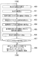
- 5 is a flowchart showing details of texture synthesis and mapping.
- 5 is a flowchart showing details of texture synthesis and mapping. It is explanatory drawing which shows the smoothing point of a boundary line. It is explanatory drawing which shows the smoothing point of a boundary line. It is explanatory drawing which shows the smoothing point of a boundary line. It is explanatory drawing which shows the smoothing point of a boundary line. It is explanatory drawing which shows the setting point of a rectangular area. It is a flowchart which shows the extraction process of the texture most similar to the texture of an overlap area
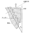
- FIG. 5 is a relationship diagram between a draft and a displacement reduction rate showing a concept of a change equation. It is a figure which shows the depth change of the aperture_diaphragm
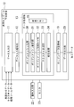
- FIG. 1 is a block diagram illustrating a configuration of a surface processing data creation apparatus according to an embodiment.
- the surface processing data creation apparatus 10 is based on data stored in the data input unit 11, the input data storage unit 12, and the input data storage unit 12 for inputting product surface shape and aperture texture data, and further processing tool data.
- a data processing unit 13 that generates polygon data in which the surface curved surface of the product is constricted, a polygon data storage unit 19 that stores the generated polygon data, and polygon data from the polygon data storage unit 19 is output as processed data.
- a data output unit 20 is connected to an operation input unit 22 including a keyboard and a jog lever and a monitor 23 capable of displaying image data.
- the surface shape data includes the entire size of the target portion to which the product is to be narrowed (hereinafter referred to as a narrowing target).
- the texture data is 256-gradation two-dimensional grayscale image data in which the aperture depth is assigned to the density.
- the texture data can be expressed with a small amount of data, and data processing is simple. In addition, processing can be performed even with a polygon mesh area divided into areas to be described later having an area size of about 2 to 4 times the area projected onto a two-dimensional plane. In this respect, the data amount can be reduced.
- the texture data is read as a pixel value for processing by the data processing unit 13.
- the processing tool data includes the polygon mesh area division angle, the number of extended boundary lines for forming overlapping areas in the patch unit mode described below, and the optimal boundary line that determines the range to be weighted when mixing textures.
- the maximum distance from the search the number of search exclusions when searching for the optimal boundary line, the size of the predetermined area projected in the pixel unit mode, the size of each template used in the patch unit mode and the pixel unit mode, and the reduction that changes according to the draft
- the data processing unit 13 in particular, in the determination of the texture to be applied to the product surface, a predetermined region from the sample texture is used for the purpose of giving a smooth continuous diaphragm with arbitrary accuracy to a free-form surface including a non-developable surface. Applying image quilting to copy and synthesize, generate the aperture. Therefore, the data processing unit 13 includes a polygon meshing unit 30, a polygon mesh integrating unit 31, a polygon mesh region dividing unit 32, a texture synthesizing unit 33, a narrowing generating unit 34, and a work memory 35.
- the polygon meshing unit 30 creates a triangular polygon mesh on the free curved surface of each patch W, and the polygon mesh integrating unit 31 integrates the triangular polygon meshes of all the patches W constituting the surface shape data into one file data.
- the polygon mesh area dividing unit 32 divides the integrated triangular polygon mesh into areas in a normal direction, for example, a predetermined angle from the z axis, and determines an initial area.
- the texture synthesizing unit 33 sequentially maps the texture to the triangular polygon mesh in the initial area, and sequentially synthesizes and maps the constricted continuous images to the adjacent areas by texture synthesis. At this time, there is a mode in which a new texture is assigned to a region being processed, which will be described later, in units of patches and a mode in units of pixels, as selected from the operation input unit 22.
- the aperture generation unit 34 shifts the position of each vertex to generate polygon data with an aperture.
- the displacement amount is changed by applying a displacement amount reduction rate corresponding to the die drawing gradient, thereby preventing the occurrence of under-molding.
- a plurality of change formulas that determine the displacement reduction rate are set in advance, and any one of the change formulas is determined by the operation of the operation input unit 22 in consideration of the characteristics of the molding material and the product shape. It is selectable.
- processing data in each unit in the data processing unit 13 is temporarily stored.
- the data processing unit 13 causes the polygon data storage unit 19 to store the polygon data to which the aperture is given.
- the monitor 23 can display the progress of each process including images.
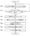
- FIG. 2 is a main flowchart showing the flow of processing.
- Product surface shape data, aperture texture data, angle information in mold opening direction, integrated polygon mesh interval upper limit b described later, polygon mesh area division angle, number of extended boundary lines to form overlapping area When the maximum distance from the optimum boundary line and the number of search exclusions are input to the data input unit 11 by the operation of the operation input unit 22, each data is stored in the input data storage unit 12, and the process is started. Along with these data inputs, the operation input unit 22 also selects a change formula that determines the texture assignment mode and the displacement reduction rate.
- step 100 the polygon meshing unit 30 reads the information of the patch W from the input data storage unit 12, and creates a triangular polygon mesh Qc.
- step 101 it is checked whether unprocessed patch information still remains in the input data storage unit 12, that is, whether the creation of the triangular polygon mesh Qc has been completed for all the patches W.
- the process returns to step 100.
- step 102 the polygon mesh integration unit 31 integrates the triangular polygon meshes Qc of all the patches W into one file integrated polygon mesh QT indicating one curved surface.
- the polygon mesh region dividing unit 32 performs region division of the integrated polygon mesh QT.
- the image is divided by an angle range calculated by the reference axis and the normal direction of the polygon mesh.
- This angle range is given as a division angle of the processing tool data.
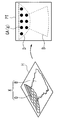
- FIG. 3A is an example of a Gaussian hemisphere, where the z-axis direction is schematically taken as the die removal direction, and 360 ° is equally divided in the longitude direction with respect to the normal direction of the mesh around the zenith that is the maximum point on the z-axis. Shows an example of 12 divisions and a latitude direction of 90 ° divided into four.
- step 104 the texture synthesis unit 33 synthesizes and maps the texture so that adjacent boundary portions smoothly change with respect to the divided polygon mesh regions.
- step 105 the aperture generation unit 34 moves each vertex of the integrated polygon mesh QT by displacement mapping based on the texture data and the processing tool data, and stores it in the polygon data storage unit 19 as polygon data to which the aperture shape is given. Store.
- the data output unit 20 can read the polygon data from the polygon data storage unit 19 by the operation of the operation input unit 22 and output the polygon data as processing data to a processing apparatus or the like.
- FIG. 4 is a flowchart showing details of the creation of the triangular polygon mesh Qc in step 100.
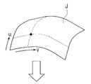
- step 200 the number of divisions of the parameters u and v for dividing the free-form surface J of the selected patch as shown in FIG. 5A so that the lattice spacing is equal to or smaller than the spacing upper limit b is calculated.
- the parameter interval (maximum value ⁇ minimum value) of u of the patch W is divided by an integer m to obtain the parameter interval c.
- the patch is divided using c, compared with the upper limit value b, and if larger than b, m is increased. This process is repeated until all the lattice intervals are smaller than the interval upper limit b. Similar processing is performed for the parameter v.
- FIG. 5B shows a dividing line on a free-form surface.
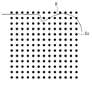
- step 201 the parameter values of each grid point are calculated using the division numbers of u and v calculated above, and points are generated on the free-form surface as shown in FIG.
- the generated point is referred to as a grid point Ca.
- FIG. 6 is an enlarged view along the uv plane, and an isoparametric curve is omitted for simplification.
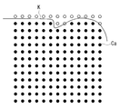
- step 202 grid points Ca for polygon mesh formation are extracted. Specifically, among the grid points Ca, as shown in white in FIG. 7, those outside the boundary line including the boundary line K of the patch W are deleted, and further, the grid points Ca are located inside the boundary line K. Even those whose distance from the boundary line is less than 1/100 of the lattice spacing are deleted.
- the lattice interval may be the interval upper limit b or the actually divided lattice interval.
- the boundary line K includes a trim line and is indicated by a B-spline curve.
- the shape of the boundary line K is arbitrary for each patch. The reason why the grid point Ca whose distance from the boundary line K is less than the predetermined distance is excluded is to avoid that the polygon formed by using the points on the boundary line K described below becomes extremely small.
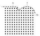
- step 203 the number of divisions for dividing the boundary line K so as to be equal to or smaller than the interval upper limit value b is calculated.
- step 204 as shown in FIG. A column Cb is generated.
- individual points in the point sequence are also represented by Cb.
- the entire circumference can be equally divided as in the case of the grid point Ca.
- the division of the grid points Ca and the point sequence Cb is equally divided by the interval upper limit b. Only the part exceeding the upper last interval upper limit b may be divided into two. As a result, the grid points and the sequence of points are each spaced uniformly within a predetermined range.
- the boundary line in each of the boundary lines K is generated so that the same point sequence Cb is generated in a range where the patches W1 and W2 of the boundary line K are adjacent to each other.
- K1 and K2 are expressed by the same curve formula. If the expressions do not match, it is assumed that the two curves match in phase, and the point sequence Cb generated on the boundary line K1 of one patch W1 is on the boundary line K2 of the other patch W2. It shall be shared as a sequence of points.
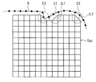
- a square lattice mesh Sqc is generated using the grid points Ca extracted in the previous step 412 as shown in FIG. In addition, although each intersection corresponds to the grid point Ca, the black circle display is omitted.
- step 206 when the outer peripheral shape of the square lattice mesh Sqc is stepped and has a concave portion, as shown in E1 and E2 portions of FIG. 10, two grid points on the outer periphery sandwiching the inner corner of the concave portion are straight lines. Are connected to form triangles ⁇ 1 and ⁇ 2. However, a triangle is not formed when the straight line connecting the two grid points crosses the boundary line K as shown by the broken line in the E3 part.
- a triangular polygon Tpc is generated by connecting a set of diagonal grid points in each lattice of the square lattice mesh Sqc. Subsequently, in step 208, a triangular polygon is also generated between the grid point Ca on the outer periphery of the square lattice mesh Sqc and the point sequence Cb on the boundary line K.
- one of the grid points Ca1 on the outer periphery is selected and connected to the point Cb1 on the boundary line K closest thereto.
- Each of the connecting straight lines R0 as one side, and a triangle ⁇ Ca1-Cb1-Ca2 composed of adjacent grid points Ca2 on the outer periphery of the square lattice mesh Sqc and a triangle ⁇ Ca1- composed of adjacent points Cb2 on the boundary line K Cb1-Cb2 is calculated, and the closest of the two triangles to the regular triangle is adopted as the triangle polygon Tpc.
- Whether or not it is close to an equilateral triangle is determined to be closer to an equilateral triangle as the difference between the maximum inner angle and the minimum inner angle of the triangle is closer to 0 (zero), or the ratio of the length of the longest side to the length of the shortest side is 1. It can be determined that the closer to, the closer to an equilateral triangle.
- the above processing is repeated for grid points (for example, Ca2) on the outer periphery of the square grid mesh Sqc that is sequentially adjacent to the selected grid point Ca1.
- the order in which the processing is repeated may be determined in advance so that the processing is repeated in the direction adjacent to the counterclockwise or clockwise direction.
- a triangular polygon mesh Qc expanded from the outer periphery of the square lattice mesh Sqc to the point sequence Cb on the boundary line K is generated on the free curved surface J of the patch.
- the triangular polygon mesh Qc is shaped by edge swap.
- the triangular polygon mesh generated in step 208 is a process of selecting and generating a triangle that is close to a good regular triangle for each step. However, when the entire generated triangular polygon mesh is viewed, it is more effective by edge swapping. In some cases, a good triangle can be generated.
- the grid point Ca3 on the outer periphery of the square lattice mesh Sqc indicated by the broken line in FIG. 13 and the point Cb3 on the boundary line are connected, and one ridgeline R1 in which a triangular polygon exists on both sides thereof is indicated by a thick solid line.
- the ridgeline R2 that connects the point Cb4 on the boundary line constituting one triangle polygon and the grid point Ca4 on the outer circumference constituting the other triangle polygon is calculated. Then, two triangles (triangles after edge swap) formed on both sides of the new ridge line R2 are obtained.
- two triangles ⁇ Ca4-Cb4-Ca3 and ⁇ Ca4-Cb4-Cb3 after edge swapping are two triangles ⁇ Ca3-Cb3-Cb4 and ⁇ Ca3-Cb3-Ca4 before edge swapping. If the triangle is closer to the regular triangle, the broken ridge line R1 is eliminated, and the triangles ⁇ Ca4-Cb4-Ca3 and ⁇ Ca4-Cb4-Cb3 after the edge swap are replaced as triangle polygons and adopted.
- the triangular polygon mesh Qc is shaped by repeating the above processing for the grid points that are sequentially adjacent on the outer periphery of the square lattice mesh Sqc. As described in the processing of step 204, between patches that share a boundary line, the point sequence of the boundary line is shared. Therefore, in the integration of the triangular polygon mesh Qc in step 102, each patch is one continuous sheet.
- the grid point Ca and the point Cb on the boundary line become the vertex pc (see FIG. 12) of the integrated polygon mesh QT.
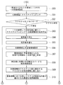
- step 300 a region-specific ID is assigned to the triangular polygons forming each region of the integrated polygon mesh divided in step 103, and one region is set as an initial region.
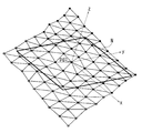
- the region surrounding the zenith is integrated into one region in consideration of projecting in the z-axis direction, and this is defined as the initial region A.
- step 301 the texture synthesis unit 33 extracts an arbitrary texture GA that covers the initial region A from the texture data stored in the input data storage unit 12, and sets the reference direction (z-axis direction) to the initial region A. Then, the pixel value information of the texture is mapped (hereinafter simply referred to as texture mapping).
- step 302 it is checked whether the previously selected texture assignment is the patch unit mode or the pixel unit mode. When the mode is the patch unit mode, the process proceeds to step 303, and when the mode is the pixel unit mode, the process proceeds to step 320.
- step 303 as preparation for setting the overlapping area, a boundary line F0 that goes around the periphery of one adjacent area B (see FIG. 3B) adjacent to the initial area A is searched by following the vertices of the triangular polygons. Since each triangle polygon is assigned an ID unique to the region, it can be searched efficiently.
- step 304 the searched boundary line F0 is smoothed in order to simplify the expansion of the boundary line performed in the subsequent stage. Specifically, as shown in FIG. 16, if two continuous ridgelines constituting the boundary line F0 are two sides of one triangle, the remaining one side of the triangle instead of the two sides The boundary line F1 is replaced with the ridgeline.
- the black circles in the figure are the vertices of the polygon mesh.
- step 305 as shown in FIG. 17A, the vertices on the smoothed boundary line F1 are sequentially traced in the direction indicated by the arrow, and the vertex of the other end of the ridge line (broken line) connected to each vertex (black circle) is obtained.
- This is a boundary line F2 extended by connecting.
- FIG. 17B based on the boundary line F2, similarly, the other end of the ridge line connected to each vertex is connected to form a boundary line F3.
- FIG. 17C shows the setting of the boundary line F4 based on the boundary line F3.
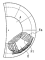
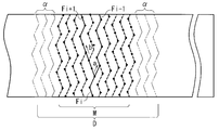
- a multiplexed boundary line Fm as shown in FIG. 3C By sequentially repeating the expansion of the boundary line F up to the number of expansions set as processing tool data, a multiplexed boundary line Fm as shown in FIG. 3C can be obtained.
- the overlap area to be described later is for smoothly connecting textures within the area.
- the expanded number of boundary lines F indicates the area range of the overlap area, the texture characteristics and the details of the polygon mesh. In consideration of this, it is set in advance.
- the innermost side of the boundary line Fm shown in FIG. 3C is the boundary line F1.
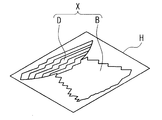
- an area that overlaps the initial area A and is surrounded by the multiplexed boundary line Fm is set as an overlapping area D.
- the triangular polygon is planarized with the median of the angular range of the adjacent region B given as processing tool data when dividing the adjacent region B searched for the overlap region D and the boundary line F0 as the normal direction. Project to 2D.
- the adjacent region B searched for the boundary line F0 and the overlapping region D are combined and are also referred to as a “processing region” X in the sense that it is a processing target to be mapped from now on.
- a rectangular area H that covers the area X being processed on the projection plane is set.
- step 309 the texture GB most similar to the overlapping region D portion in the texture GA mapped to the initial region A is searched from the texture data by template matching and assigned to the rectangular region H.
- FIG. 19 is a flowchart showing details of the procedure for extracting the most similar texture GB. If there are n vertices in the initial region A in the overlapping region D, each vertex has pixel information of the texture GA. Therefore, in step 330, as shown in FIG. 20A, a template PT having the same size as that of the rectangular area H including the n pixel values of the overlapping area D is set.
- step 331 the square value of the difference between the pixel value GA (g) of the vertex in the template PT and the pixel value GS (g) of the texture data while shifting the texture data in the xy direction.
- Is calculated as follows. Sum of differences between the pixel value GS (g) in the texture data and the pixel value GA (g) of the rectangular area H (GS 1 (g) ⁇ GA 1 (g)) 2 + (GS 2 (g) ⁇ GA 2 (G)) 2 +... + (GS n (g) ⁇ GA n (g)) 2 Then, the template PT position having the smallest total value is determined.
- step 332 the texture at the template PT position with the smallest sum of the differences between the pixel value GS (g) and the pixel GA (g) is taken as the most similar texture, and the texture GB corresponding to the rectangular area H is cut out.
- the texture GB is filled up.
- a broken line in the figure is a multiplexed boundary line Fm.
- the polygon mesh has vertices indicated by black circles only on the boundary lines.
- “optimal boundary line” for smoothly connecting the texture GA of the initial region A and the texture GB assigned to the region X being processed in the overlapping region D in step 310.
- Search for FS That is, image quilting for obtaining the boundary line FS that minimizes the difference between the pixel values is performed.
- the search for the optimum boundary line FS is performed as a search area M in an intermediate area excluding ⁇ boundary lines at both ends of the overlap area D.
- the search exclusion number ⁇ is stored as processing tool data in the input data storage unit 12 and will be described in detail later.
- an arrow a indicates an example of movement from the boundary line Fi to the vertex of the boundary line Fi-1
- an arrow b indicates an example of movement from the boundary line Fi to the vertex of the boundary line Fi + 1.
- the search is started from all the boundary lines of the search area M, and the one having the smallest difference in pixel values in the entire path is set as the optimal boundary line FS.
- the pixel value at the vertex position is calculated by bilinear interpolation from the pixel values of the surrounding four pixels. Further, in a region where the texture is not yet mapped (adjacent region B), the pixel value difference is set to 0 (zero) and the current position is traced on the boundary line.
- the optimum boundary line FS obtained in this way divides the end of the texture GB to be mapped to the region X being processed, and the texture GB on the optimum boundary line FS.
- both textures can be smoothly connected with a small change in pixel value.
- the new texture is connected to the existing texture with a change in the level at which the difference between the pixel values of the texture of the initial region A and the new texture (that is, the texture assigned to the region X being processed) is the smallest. become.
- step 311 the optimum boundary line FS is centered.
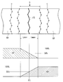
- the pixel values of the texture GA and GB are weighted with the optimum distance from the boundary line FS and mixed.
- the object to be mixed is set to the pixel value of the vertex in the range of Lmax in both directions from the optimum boundary line FS.
- the pixel value GA (g) of the texture GA and the pixel value GB (g) of the texture GB are 50% each, and from the optimal boundary line FS from the optimal boundary line FS on the adjacent region B side.
- the ratio of the pixel value GA (g) is decreased and the ratio of the pixel value GB (g) is increased.
- the ratio of the pixel value GA (g) is 0, and the pixel value GB (G) is set to 100%.
- the ratio of the pixel value GA (g) increases, the ratio of the pixel value GB (g) decreases, and the position of Lmax
- the ratio of the pixel value GA (g) is set to 100% and the pixel value GB (g) is set to 0 at the vertices. That is, the pixel value GR of each vertex after mixing is expressed by the following equation, where L is the distance from the optimal boundary line, and positive (+) is the direction opposite to the adjacent region B from the optimal boundary line.
- GR (g) GA (g) (Lmax + L) / 2Lmax + GB (g) (Lmax-L) / 2Lmax As the distance L from the optimum boundary line of the vertex, the shortest distance from the vertex to the optimum boundary line is used.
- the search for the optimum boundary line FS is limited to the search area M excluding the search exclusion number ⁇ at both ends in the overlapping area.
- the texture GB is not assigned to the initial region side of the optimum boundary line FS, and therefore, the purpose is to avoid the case where mixing is not possible. For this reason, even when the optimum boundary line FS passes through the vertex on the boundary line at the end of the search region M, the texture GB is assigned to the vertex in the range of the optimum boundary line FS to Lmax. It is positioned within the overlapping area so that pixel values can be mixed. Therefore, the search exclusion number ⁇ is preferably set to a value with a slight margin in the number of boundary lines that can cover the distance of Lmax. Similarly, the search exclusion number ⁇ is also set on the adjacent area side in the overlap area so that the pixel values can be mixed in the overlap area.
- step 312 the texture in which the pixel values are mixed in the overlapping region D is mapped to the region X being processed.
- the texture GA of the initial region A and the texture GB mapped to the region X being processed are more smoothly connected between 2Lmax centered on the optimum boundary line.
- step 313 it is checked whether texture mapping has been completed for all the divided regions.
- step 314 If an unprocessed area remains, in step 314, the initial area A and the area X being processed are integrated into a new initial area, the triangle polygon ID is reset, and the process returns to step 303.
- the processing up to step 312 is repeated.
- texture synthesis is performed in the above patch unit mode, the size cut out from the texture data is large, so that the aperture feature indicated by the texture data input to the data input unit 11 can be held faithfully. There is an advantage that the calculation time in processing does not require much.
- texture mapping is completed for all regions, the process proceeds to step 105.
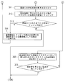
- step 320 branched from step 302, a template matching is performed on the boundary portion between the area where the texture has already been mapped and the pixel value (starting area A as a start) and the area not having the pixel value (adjacent area B). Then, pixels that are smoothly connected with the smallest change with respect to the area having the pixel value are extracted from the texture data, and mapped to the area having no pixel value for each vertex.
- FIG. 23 is a flowchart showing details of the mapping in pixel units.
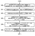
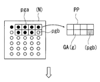
- step 340 a vertex that does not have a pixel value adjacent to a vertex of a region having a pixel value is searched for, and this vertex is set as a target vertex pgb for determining a pixel value.
- step 341 as shown in FIG. 24A, local coordinates having the normal direction at the vertex obtained from the polygon adjacent to the target vertex pgb as the Z coordinate axis are set, and in step 342, shown in FIG. 24B.
- the predetermined area N including the target vertex pgb such as 1 mm in the x direction and 1 mm in the y direction, is projected onto the xy plane of the local coordinates to be two-dimensional.
- the projected vertices are within the range specified by searching for the vertices around the target vertex pgb in the order of one layer (vertex connected by one ridgeline), two layers (vertex connected by two ridgelines), and three layers in order. Are all vertices.
- the vertices are not always arranged regularly.
- the vertex position is projected onto the xy plane of local coordinates as described above, and the pixel value at that position is calculated. Need to be confirmed.
- the pixel value GA (g) at the vertex is obtained by bilinear interpolation from the pixel values of the surrounding four pixels at the position projected onto the xy plane.
- step 343 as schematically shown in FIG. 25A, a region including a plurality of vertices pga having pixel values and a target vertex pgb having no set pixel value is set as a template PP.
- a black circle indicates a vertex pga having a pixel value
- a white circle indicates a vertex having no pixel value
- a white circle in the region designated as the template PP is a target vertex pgb for determining a pixel value.
- the arrangement of the vertices shown in FIGS. 25A and 25B is not matched with FIG.
- the pixel value of the vertex pga is outlined, and the target vertex portion having no pixel value is hatched.
- the position of the target vertex pgb in the template PP is input in advance as a processing tool together with the size of the template, and can be arbitrarily input before processing.
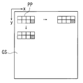
- step 344 as shown in FIG. 25B, the square value of the difference between the pixel value GA (g) of the vertex in the template PP and the pixel value GS (g) of the texture data while shifting the texture data in the xy direction.
- the template PP position having the smallest total value is searched for.
- the calculation procedure of the total value is the same as that in the extraction of the texture GB most similar to the texture GA of the overlapping region D portion in step 309.
- step 345 the texture data at the position corresponding to the vertex having no pixel value at the template PP position where the sum of the square values of the difference between the pixel value GA (g) and the pixel value GS (g) is the smallest.
- the pixel value GS (g) calculated by bilinear interpolation from the pixel values of the four pixels around is mapped to the target vertex pgb.
- step 321 it is checked whether or not vertices having no pixel value remain in the integrated polygon mesh QT. If vertices having no pixel value remain, the process returns to step 320, and pixel value extraction and mapping in units of pixels are repeated. This iterative process is repeated until there are no vertices having no pixel value over the entire surface of the polygon mesh.
- the integrated polygon mesh may be sequentially executed in each area in the order of ID numbers divided in the previous step 103. At this time, the vertex pgb to which the pixel value is mapped in step 320 is naturally changed to the vertex pga having the pixel value in the next processing.
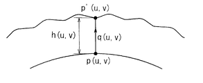
- a curved surface p ′ that is displaced by displacement mapping is expressed by Expression (1).
- p ′ (u, v) p (u, v) + h (u, v) q (u, v) (1)
- p (u, v) is a curved surface (basic curved surface) before displacement
- h (u, v) is a displacement amount
- q (u, v) is a unit vector in a displacement direction. is there. Therefore, here, each vertex pc at the position of p (u, v) in the polygon mesh QT is displaced by the above equation.
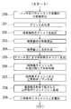
- FIG. 27 is a flowchart showing details of the stop shape assignment in the stop generation unit 32 in step 105.
- step 400 one of the vertexes pc of the integrated polygon mesh QT is selected, and the normal direction of the vertex pc is calculated.
- the position of the selected vertex is arbitrary.
- the normal direction may be obtained from a free-form surface using the parameter value of the vertex pc, or may be obtained as an average of normal directions of surrounding polygons including the vertex pc. This normal direction becomes the unit vector q when the vertex is displaced later and when the draft is calculated.
- the draft is calculated based on the mold opening direction of the machining target mold that is set in advance and stored in the input data storage unit 12 and the normal direction of the vertex coordinates.
- the displacement amount reduction rate at the apex position is obtained based on the expression for changing the drawing depth with respect to the draft selected at the start of processing.
- the draft is an angle ⁇ between the direction that forms 90 ° with respect to the normal direction of the apex and the mold opening direction indicated by the white arrow, the smaller the draft, the larger the under.
- the mold at the time of mold opening interferes with the restriction on the product side. For this reason, as shown in FIG.
- the change equation is set so that the displacement amount reduction rate increases as the draft angle ⁇ decreases (that is, the displacement amount decreases). At this time, the change equation is determined in consideration of the fact that the actual interference between the mold and the product is slightly relaxed due to the resin shrinkage after molding. The displacement reduction rate changes continuously according to the draft.
- step 403 the pixel value (density) g is read from the vertex information stored in the working memory.
- step 404 a reference displacement amount of the vertex is obtained based on the conversion rate of the pixel value g and the aperture depth.
- the maximum aperture depth that is, the maximum displacement amount is h max
- the conversion rate is h max / 255
- the reference displacement amount h is 150 ⁇ m.
- the final displacement amount is calculated by multiplying the reference displacement amount h by the displacement amount reduction rate.
- the displacement reduction rate is 0%
- the final displacement hf remains 200 ⁇ m
- the displacement is reduced in the range of 0 ° to 25 °.
- the final displacement amount hf can be changed from 20 ⁇ m to 200 ⁇ m at a rate of 90 to 0%.
- the final displacement amount hf obtained above is set to h (u, v), and the vertex pc of the polygon mesh QT is displaced by the above-described equation (1) using the unit vector q (normal direction).
- step 407 it is checked whether or not there are vertices that have not been subjected to the above processing. If unprocessed vertices remain, the process returns to step 400 and the process up to step 406 is repeated.
- the process proceeds from step 407 to step 408, where the vertices pc at the new displaced positions are connected to create polygon data with a narrowed shape.
- This polygon data is stored in the polygon data storage unit 19. According to this polygon data, when the draft angle is small, the depth (height) of the diaphragm Rs can be reduced as shown in FIG. A continuously changing product is obtained.
- the white arrow indicates the mold opening direction.
- the process of creating the narrowed polygon data ends.
- the texture unit is provided with the patch unit mode and the pixel unit mode, for example, when the patch unit mode is selected, the polygon data storage unit 19 is operated by the operation input unit 22 after the series of processing ends.
- the polygon data can be read out from the data and displayed on the monitor 23 for confirmation.
- textures are assigned in units of patches, it is possible to faithfully retain the aperture feature indicated by the texture data input to the data input unit 11 and not require much computation time in processing. There are advantages.
- reference numerals 100 to 102 in the flowchart of FIG. 2 constitute polygon meshing means in the invention, and step 103 corresponds to polygon mesh area dividing means.
- Steps 300 to 314 in the flowcharts of FIGS. 14 and 15 constitute the texture synthesis / mapping means in the invention of claim 24.
- steps 303 to 306 are the overlapping area setting means
- steps 307 and 308 are the rectangular area setting means.
- Step 309 constitutes a texture assigning means
- Step 310 constitutes an optimum boundary line searching means.
- Steps 311 and 312 constitute image quilting means, and steps 313 and 314 constitute initial area resetting means.
- the texture GB mapped to the region X being processed and “connected to the texture GA mapped to the initial region A at the“ optimal boundary line ”FS that minimizes the difference in pixel values” is “predetermined in the present invention.
- Steps 300 to 302, 320, and 321 constitute the texture synthesis / mapping means in the invention of claim 25.
- step 340 in the flowchart of FIG. 23 is the target vertex search means, and steps 341 to 343 are template settings.
- Step 344 constitutes template position searching means, and step 345 constitutes texture mapping means. “At the template position where the sum of the square values of the difference between the pixel value GA (g) of the vertex in the template PP including the target vertex and the pixel value GS (g) of the texture data is smallest” of the texture data corresponding to the target vertex The pixel value corresponds to a new texture “connected by a change satisfying a predetermined required level” in the present invention.
- Steps 400 to 407 in the flowchart of FIG. 27 constitute the vertex displacement means in the invention, and step 408 constitutes the narrowed polygon mesh creating means.
- the embodiment is configured as described above.
- the product shape data defined by the free-form surface input to the data input unit 11 is converted into a polygon mesh, and one of the divided areas is input as the initial area A.
- the texture GA cut out from the sample texture data input to the unit 11 is mapped.
- a new texture GB is synthesized so as to be connected to the mapped texture GA with a smooth change, and the texture GB is mapped to the adjacent area having no texture value to map the texture to all areas of the polygon mesh. To do.
- each of the vertices of the polygon mesh QT is displaced in the normal direction based on the mapped texture, and the new polygon mesh data created by connecting the displaced vertices is subjected to the surface processing data to which the aperture is given. To do.
- the product shape data is polygon meshed and processed as curved surface data having no thickness, so that the amount of processing data can be reduced. And since new textures are synthesized in each area divided into small areas with respect to the entire product surface, it is possible to give a good-looking aperture with little distortion even in the case of a product shape whose surface is not a developable surface.
- texture data to be input to the data input unit 11 relatively small sample data may be prepared.
- an overlapping region D is set between the initial region A and the adjacent region B, and the texture of the patch unit prepared with the size of the rectangular region H in the overlapping region D is set.
- the region X being processed, which is composed of the overlapping region D and the adjacent region B.
- the mapped region X and the initial region A are reset as new initial regions, and the subsequent processing of setting the overlapping region D is repeated to map the texture to all regions of the polygon mesh. Since a relatively large texture is connected with the size of the rectangular area H, it is possible to faithfully hold the aperture feature indicated by the texture data input to the data input unit 11 and to increase the calculation time in processing. Is not required.
- the overlapping area D is set by searching for the boundary line F of the adjacent area B as a line connecting the vertices of the polygon mesh, expanding the boundary line F outwardly of the adjacent area B, and multiplexing the boundary line F.
- a region where F1, F2, F3,... Overlap with the initial region A is defined as an overlapping region D. Therefore, it is easy to set various sizes of the overlapping region D by increasing or decreasing the number of boundary lines F to be multiplexed. Since an ID is assigned to the polygon of each divided region for each region to which the polygon belongs, the search for the boundary line F can be efficiently performed by referring to the ID.
- the boundary line F0 before multiplexing is replaced with the ridge line of the remaining one side of the triangle instead of the two sides. Since the boundary line F1 is the same, the multiplexing process is simplified.
- the polygon mesh QT is divided into regions by dividing it into a predetermined angle range calculated by a predetermined reference axis and the normal direction of the polygon mesh. Therefore, the texture is mapped by appropriately selecting the angle range. It is possible to control the accuracy when doing so.
- Multiplexing of the boundary line F is performed by tracing the vertices on the boundary line F1 in order, obtaining the vertices at the other ends of the ridge lines connected to the respective vertices, connecting the vertices at the other ends in order, and outside the boundary line F1.
- the multiplexing of the boundary line F can be easily realized at every interval of the triangle unit constituting the polygon mesh.
- a region X being processed is projected onto a two-dimensional plane, a rectangular region H that covers the region X being processed is set on the projection plane, and a new texture GB is added to the rectangular region.
- the optimum boundary line FS that minimizes the difference between the pixel values of the texture GA mapped to the initial area A and the new texture GB in the overlapping area D is obtained.
- the new texture GB to be assigned to the rectangular area H cuts out the texture most similar to the overlapping area D of the texture GA mapped to the initial area A from the sample texture data including the texture GA mapped to the initial area A. Therefore, an absolute small value can be obtained as the minimum value of the difference between the pixel values, and an optimum boundary line FS with a particularly small deviation between the textures GA and GB can be obtained.
- the optimum boundary line FS is the next boundary line on the boundary line from the current vertex or the adjacent inner boundary line on the condition that the traveling direction is not reversed while going around one boundary line in the multiplexed boundary line Fm.
- it is obtained by moving to the vertex having the smallest difference in pixel values among the vertices on the outer boundary line, so that the search is easy.
- the end of the search area becomes the optimum boundary line FS.
- a predetermined range 2Lmax centered on the optimum boundary line can be secured.
- the texture value of the texture GA mapped to the initial area A in the predetermined range 2Lmax and the texture value of the new texture GB allocated to the rectangular area H can be weighted with the optimum distance from the boundary line FS and mixed.
- the texture change from the area A to the adjacent area B becomes particularly smooth.
- the synthesis of a new texture in pixel units is performed as follows. First, a vertex that does not have a pixel value adjacent to a vertex of a region having a pixel value is searched, the vertex is set as a target vertex for determining the pixel value, and a predetermined region including the target vertex is projected onto a two-dimensional plane. Then, a template including a target vertex and a plurality of vertices having texture values adjacent thereto is set on the projection plane. Then, the template position where the difference between the texture data and the texture value of the template is minimized is searched, and the texture value of the texture data corresponding to the target vertex position in the template at the searched template position is mapped to the target vertex. Go. Therefore, it is possible to synthesize a new texture with high accuracy that smoothly changes without performing pixel value mixing processing or the like.
- Polygon meshing of product shape data is performed by dividing the product shape data into a plurality of patches, generating grid points with predetermined dividing lines in the parameter space of the free-form surface of each patch, and predetermined on the patch boundary line. Generate a sequence of points at intervals of, and use the grid points inside the boundary line and the point sequence on the boundary line to form a 3D polygon mesh with each vertex on a free-form surface. This is done by integrating them into one polygon mesh. After forming the polygon mesh for each of the plurality of patches W obtained by dividing the surface shape data, the polygon meshes of all the patches are integrated into one polygon mesh Qc. Therefore, the surface shape data can be obtained by repeating a small number of calculation processes for each patch. The entire polygon mesh can be easily created.
- the dividing lines for generating the grid points and the point sequences on the boundary line are arranged so as to have a uniform interval within a predetermined range, and a three-dimensional polygon mesh is formed by connecting grid points inside the boundary line.
- a mesh is formed, and the lattice mesh is formed into a triangular polygon, and a triangular polygon is formed by connecting grid points on the outer periphery of the lattice mesh and a sequence of points on the boundary line. Therefore, since the projection of the 3D polygon mesh onto the 2D plane and the process of restoring the triangle polygon to 3D are not performed, the calculation burden is reduced and the processing time is shortened. Similarly, there is no distortion caused by the two-dimensional and three-dimensional processes. Moreover, since the point sequence on the boundary line is shared at the same position between adjacent patches, it is easy to integrate each patch into one polygon mesh continuously without a break.
- the displacement amount for displacing each vertex of the polygon mesh is set by multiplying the basic displacement amount based on the texture by the displacement amount reduction rate corresponding to the draft of the mold. Therefore, a drawing shape having a good-looking appearance surface can be obtained by smoothly changing the depth of drawing without causing under-molding.
- the aperture feature indicated by the texture data input to the data input unit 11 can be held faithfully, and the computation time required for processing does not require much.
- the texture of the aperture is a geometric pattern composed of straight lines and curves such as squares and circles, deviations may remain even if pixel values are mixed.
- the pixel unit mode can also be selected, so that it may take a little processing time depending on the target level, but the pixel unit mode can synthesize a texture without discontinuity such as a shift. it can.
- the size of the surface-shaped patch W may be arbitrarily determined according to the processing capability of the computer of the surface processing data creation apparatus 10.
- an example of generating a triangular polygon mesh in units of individual patches defined by patch information input to the data input unit 11 has been described.
- the surface shape data is small and corresponds to one patch
- the example in which the B-spline curve is used as the free curve of the boundary line has been described.
- the present invention can be similarly applied to other free curves.
- step 311 in the texture synthesis in the patch unit mode at the joint portion of the region where the integrated polygon mesh QT is divided into regions, in step 311, the texture GA and GB on both sides centering on the optimum boundary line FS.
- the pixel values are mixed, but due to the characteristics of the texture, the fineness of the polygon mesh, etc., the connection between the texture GA and GB on the optimum boundary line FS as shown in FIG. In this case, the pixel value mixing process can be omitted.
- the texture data is provided as 256 gray scale image data.
- image data in which the depth information about the concentration of a plurality of color components is provided may be used.
- the direction in which each vertex pc of the polygon mesh QT is displaced based on the texture data of the aperture is the normal direction, but this can also be set to an arbitrary direction.
- the reduction rate is continuously changed for the reduction of the displacement against the draft, but it is naturally possible to intentionally make a stepwise change at any step. It is.
- the change equation for determining the displacement reduction rate is selected at the start of processing together with the input of the surface shape data and texture data. However, after the displacement mapping stage, the monitor 23 displays a display requesting selection. The displacement mapping process may be started after waiting for the selection operation.
- the present invention has a great effect when used in the field of manufacturing various resin products that form a drawn pattern on the product surface.
Landscapes
- Engineering & Computer Science (AREA)
- Physics & Mathematics (AREA)
- Computer Graphics (AREA)
- General Physics & Mathematics (AREA)
- Theoretical Computer Science (AREA)
- Geometry (AREA)
- Software Systems (AREA)
- Image Generation (AREA)
- Moulds For Moulding Plastics Or The Like (AREA)
- Shaping Of Tube Ends By Bending Or Straightening (AREA)
- Processing Or Creating Images (AREA)
Abstract
可展面でない製品形状であっても、製品表面に歪みの少ない、見栄えの良い絞が形成される表面加工データを作成する。ポリゴンメッシュ化した製品表面を領域分けし、初期領域AにテクスチャGAをマッピングする。隣接領域Bの境界線を外方へ多重化して初期領域との間に重複領域Dを設け、処理中の領域X(重複領域+隣接領域)を2次元平面に射影してテクスチャGBを割り当てる。重複領域で両テクスチャGA、GBの画素値の差が最小となる最適な境界線FSを求め、最適な境界線でテクスチャGAにつなげてテクスチャGBを処理中の領域Xにマッピングする。最適な境界線を中心に画素値の混ぜ合わせもできる。初期領域と隣接領域とを新たな初期領域として上記を繰り返し、全領域にマッピングしたテクスチャに基づいて変位させたポリゴンメッシュの頂点を結び、絞付与ポリゴンデータとする。
Description
本発明は、樹脂製品の表面に絞(しぼ)模様を形成するための表面加工データの作成方法および装置に関する。
家電製品、文具、または自動車用内装品などの表面には、見栄えや触感の向上、防眩、滑り止めなど様々な目的で絞が施されている。絞の模様には皮革、木目、岩目、砂目、なし地、幾何学模様などさまざまな微細形状の模様が採用されている。これらの絞を樹脂製品の表面に形成するために、従来はエッチング工法や電気鋳造法などにより成形金型に絞模様が付与されている。
上記エッチング工法は、腐食により形状を生成するため、大型の製品の成形金型にも適用できかつ安価であるが、細かな形状表現が難しく、また繰り返し同一形状を作成することも難しい。
また、絞を製品曲面の法線方向に形成する場合、射出成形金型の型開き方向にそった面で製品取り出し方向と製品曲面が交差する所謂アンダーが生じると、成形品の取り出し時に型の絞の凸凹と成形品に転写された絞の凸凹が引っ掛かることになり、成形品を強引に金型から取り出せば成形品の絞が損傷を受ける。これを避けるために型開き方向にそった抜き勾配(製品曲面の法線方向と製品取り出し方向とのなす角の90°の補角)が0°に近い領域になるほど抜き勾配の変化に応じて絞の深さを浅くしてアンダーの発生を回避する必要がある。
また、エッチング工法によって絞模様を成形金型に付与する場合は、連続的に絞の深さを変化させることができず、段階的に浅くするとそのつなぎ目が露わになって見栄えを損なうことになる。
また、絞を製品曲面の法線方向に形成する場合、射出成形金型の型開き方向にそった面で製品取り出し方向と製品曲面が交差する所謂アンダーが生じると、成形品の取り出し時に型の絞の凸凹と成形品に転写された絞の凸凹が引っ掛かることになり、成形品を強引に金型から取り出せば成形品の絞が損傷を受ける。これを避けるために型開き方向にそった抜き勾配(製品曲面の法線方向と製品取り出し方向とのなす角の90°の補角)が0°に近い領域になるほど抜き勾配の変化に応じて絞の深さを浅くしてアンダーの発生を回避する必要がある。
また、エッチング工法によって絞模様を成形金型に付与する場合は、連続的に絞の深さを変化させることができず、段階的に浅くするとそのつなぎ目が露わになって見栄えを損なうことになる。
一方、電気鋳造法は、製品形状に製作されたモデル表面に絞をエンボス加工した薄い樹脂シートを手作業で貼り合せ、これをマスターモデルとして樹脂反転や電気鋳造工程を経て成形型とする。しかし、立体形状のモデルに樹脂シートを貼る際に伸びや歪みが生じ、あるいはつなぎ目の模様に不整合が生じるのでこれらを目立たないように修正するのに作業者の熟練を要する。さらに、多くの工程を要する結果工期が長くコスト高となるので、専用の設備を持つ専業メーカでしか電気鋳造法を採用できない。そして、絞の形状、サイズはマスターモデル作成時に貼り合わせる樹脂シートの絞で決定され、あとで任意の部位に追加の模様を付したり、絞模様の拡大、縮小も困難である。
そして両工法とも、薬液処理等が必要であるというデメリットをもつ。
そして両工法とも、薬液処理等が必要であるというデメリットをもつ。
また、より簡便にかつ品質の高い絞形成を可能とするために、例えば特許文献1や特許文献2で公知な方法も提案されている。この方法は、皮革モデルなどの表面形状を読み取った表面測定値から表面形状の深さを256階調の濃度で表わした画像データに変換することにより、絞模様の形状データをデジタル化して、これに基づいてコンピュータにより加工データを生成し、この加工データを用いて、例えば、エンボスロールやエンボス板などの平面的なものに絞を付与するものや、切削加工やレーザ加工により絞を金型などの立体的なものに付与するものである。
この絞形状データから加工データを生成するに当って、金型などの3次元形状の立体物表面に投影した加工データとするだけでは、立体物の傾斜面において個々の絞が延びて歪んでしまうので、絞は曲面の製品表面に対してその法線方向に形成される必要がある。
このため、絞を製品表面の法線方向に形成するものとして、例えば画像データにおける絞の深さに対応する濃度に応じて、製品曲面上にボクセルを積み上げて絞を生成するボクセルデータ変換を用いたモデリングソフトなどが提供されている。
このため、絞を製品表面の法線方向に形成するものとして、例えば画像データにおける絞の深さに対応する濃度に応じて、製品曲面上にボクセルを積み上げて絞を生成するボクセルデータ変換を用いたモデリングソフトなどが提供されている。
このボクセル方式では、製品形状データを小さな球や立方体で構成するボクセルデータに変換し、それぞれのボクセルデータに対応する絞の画像データの画素を決定する。そして、当該画素の濃度を変位量に換算してボクセルデータ上に変位量に相当するボクセルを積み上げる。これをポリゴンデータに変換して最終データとする。
しかしながら、上述の方式では、先ず製品形状データをボクセルデータに変換するために膨大なデータ量を必要とする。
さらに、一般のコンピュータのデータ処理能力を勘案すると、複数の曲面からなる連続した複雑形状の製品表面に対しては、分割した範囲ごとに絞を生成し、絞生成後に隣接する絞形状とのつなぎ目処理が必要となるが、これに対する満足な処理が未解決である。
さらに、一般のコンピュータのデータ処理能力を勘案すると、複数の曲面からなる連続した複雑形状の製品表面に対しては、分割した範囲ごとに絞を生成し、絞生成後に隣接する絞形状とのつなぎ目処理が必要となるが、これに対する満足な処理が未解決である。
すなわち、つなぎ目の絞を同じ形状で合せることが難しく、つなぎ目が目立たないようにするには多大な工数を要する手作業による修正が必要となる。しかも、手作業による修正はつなぎ合わせようとする絞形状を変形させることとなるので、作業者の熟練度により出来栄えが変り、角が丸くなったり、溝や山が太くなったり、曲がったりして、修正の狙いから外れて見栄えの悪いものとなってしまうことも多く、品質が安定しない。したがって従来の手法はその主な適用対象が平面や円筒面に限定されているのが実情である。
そこで、本出願人は、製品形状を自由曲面上でポリゴンメッシュ化し各々の頂点に局所座標を設定することで3次元空間上の方向と実距離を算出し、直接にテクスチャ情報を取得する手法をすでに提案した。これによれば、平面に展開できる可展面はもちろん、可展面ではないがガウス曲率が緩い場合にも対応でき、メータフード部の折り返し等、一価関数として表現できない形状への絞付与が少ない演算時間で可能となる。
しかし、可展面でなくガウス曲率が大きかったり、あるいはガウス曲率が緩くても面積が広くなる多数の曲面で構成されている製品形状の場合には、局所座標の基点から遠ざかるほどテクスチャ上での間隔が広がって歪みが拡大するおそれが残っている。
しかし、可展面でなくガウス曲率が大きかったり、あるいはガウス曲率が緩くても面積が広くなる多数の曲面で構成されている製品形状の場合には、局所座標の基点から遠ざかるほどテクスチャ上での間隔が広がって歪みが拡大するおそれが残っている。
したがって本発明は、さらなる改良を図り、ガウス曲率が大きかったり、あるいはガウス曲率が緩くても面積が広くなる多数の曲面で構成される製品形状であっても、過大なデータ量を必要としない簡単な処理で製品表面に歪みの少ない絞が形成されるようにした表面加工データの作成方法および装置を提供し、また、データを分割したとしても絞形状のつなぎ目が滑らかな表面加工データを作成できる表面加工データの作成方法および装置を提供することを目的とする。
上記目的を達成するために、本発明によれば、
自由曲面で定義される絞付与対象の製品形状データをポリゴンメッシュ化し、
前記ポリゴンメッシュを領域分けし、
領域分けした領域の1つを初期領域に設定して、前記初期領域にテクスチャデータに基づくテクスチャをマッピングし、
前記マッピングされたテクスチャに所定の要求レベルを満たす変化でつながる新たなテクスチャを合成し、
前記テクスチャデータを合成した領域に隣接しテクスチャ値を有しない領域に前記新たなテクスチャをマッピングすることを繰り返して前記ポリゴンメッシュのすべての領域にテクスチャをマッピングし、
ポリゴンメッシュの各頂点を前記ポリゴンメッシュにマッピングされたテクスチャに基づいてそれぞれの法線方向に変位させ、
変位させた前記各頂点に基づいて新たなポリゴンメッシュデータを作成して、前記新たなポリゴンメッシュデータを絞が付与された表面加工データとする表面加工データの作成方法が提供される。
ポリゴンメッシュの領域分けは、予め定めた基準軸とポリゴンメッシュの法線方向とで算出される所定の角度範囲で分割することが好ましい。
製品表面全体に対して小さく領域分けされた各領域で新たなテクスチャの合成を進めるので、テクスチャデータは製品表面全体をカバーするサイズは必要なく、比較的小サイズのサンプルデータを準備するだけで済む。
自由曲面で定義される絞付与対象の製品形状データをポリゴンメッシュ化し、
前記ポリゴンメッシュを領域分けし、
領域分けした領域の1つを初期領域に設定して、前記初期領域にテクスチャデータに基づくテクスチャをマッピングし、
前記マッピングされたテクスチャに所定の要求レベルを満たす変化でつながる新たなテクスチャを合成し、
前記テクスチャデータを合成した領域に隣接しテクスチャ値を有しない領域に前記新たなテクスチャをマッピングすることを繰り返して前記ポリゴンメッシュのすべての領域にテクスチャをマッピングし、
ポリゴンメッシュの各頂点を前記ポリゴンメッシュにマッピングされたテクスチャに基づいてそれぞれの法線方向に変位させ、
変位させた前記各頂点に基づいて新たなポリゴンメッシュデータを作成して、前記新たなポリゴンメッシュデータを絞が付与された表面加工データとする表面加工データの作成方法が提供される。
ポリゴンメッシュの領域分けは、予め定めた基準軸とポリゴンメッシュの法線方向とで算出される所定の角度範囲で分割することが好ましい。
製品表面全体に対して小さく領域分けされた各領域で新たなテクスチャの合成を進めるので、テクスチャデータは製品表面全体をカバーするサイズは必要なく、比較的小サイズのサンプルデータを準備するだけで済む。
上記新たなテクスチャの合成は、前記初期領域とこれに隣接する隣接領域との間に重複領域を設定し、前記重複領域においてパッチ単位で合成し、ポリゴンメッシュのすべての領域へのテクスチャのマッピングは、前記重複領域と前記隣接領域とからなる処理中の領域にパッチ単位で合成した新たなテクスチャをマッピングし、前記マッピングした処理中の領域と前記初期領域とを新たな初期領域として、新たなテクスチャの合成を繰り返させて行うものとすることができる。
あるいは、上記新たなテクスチャの合成は、ピクセル単位で、テクスチャがマッピングされた領域との境界に隣接するテクスチャ値を有しない頂点ごとに画素情報を定めることで合成し、ポリゴンメッシュのすべての領域へのテクスチャのマッピングは、ピクセル単位で合成した新たなテクスチャを上記頂点にマッピングし、新たなテクスチャの合成をテクスチャ値を有しない頂点ごとに繰り返して行うこともできる。
さらには、上記パッチ単位の合成とピクセル単位の合成を選択可能なモードとすることもできる。
さらには、上記パッチ単位の合成とピクセル単位の合成を選択可能なモードとすることもできる。
また、パッチ単位のテクスチャ合成における重複領域の設定は、隣接領域の他の領域との境界線をポリゴンメッシュの頂点を結ぶ線として探索し、境界線を隣接領域の外方へ拡大して多重化し、前記多重化した境界線が初期領域と重なる領域を重複領域とすることができる。
この際、領域分けした各領域のポリゴンには、前記ポリゴンが属する領域ごとのIDを付与しておくことにより、境界線の探索をそのIDを参照して行うことができ効率が良くなる。
この際、領域分けした各領域のポリゴンには、前記ポリゴンが属する領域ごとのIDを付与しておくことにより、境界線の探索をそのIDを参照して行うことができ効率が良くなる。
境界線の多重化は、境界線上の頂点を順番に辿って、各頂点に接続する稜線の他端の頂点を求め、前記他端の頂点を順番に繋いで境界線の外側に新たな境界線を拡張することを順次繰り返すことにより、複数の拡張した境界線を得ることができ、多重化の前に最初の境界線を平滑化しておくと、拡張処理が単純化される。
パッチ単位の新たなテクスチャの合成は、処理中の領域を2次元平面に射影し、射影面に処理中の領域をカバーする矩形領域を設定し、前記矩形領域に新たなテクスチャを割り当て、重複領域において、前記初期領域にマッピングされたテクスチャと新たなテクスチャのテクスチャ値の差が最小となる最適な境界線を求め、前記最適な境界線で前記初期領域にマッピングされたテクスチャに上記新たなテクスチャをつなげるイメージキルティング手法を採ることができる。
矩形領域のサイズで比較的まとまったテクスチャをつないでいくので、テクスチャデータが示す絞の特徴を忠実に保持することが可能であるとともに、処理に要する演算時間も多くを要しない。
矩形領域のサイズで比較的まとまったテクスチャをつないでいくので、テクスチャデータが示す絞の特徴を忠実に保持することが可能であるとともに、処理に要する演算時間も多くを要しない。
矩形領域に割り当てる新たなテクスチャは、初期領域にマッピングしたテクスチャを含むテクスチャデータから、初期領域にマッピングしたテクスチャの重複領域部分と最も類似するテクスチャを切り出して使用するのが好ましく、初期領域にマッピングされたテクスチャと新たなテクスチャ間のズレがとくに小さい最適な境界線が得られる。
したがって、新たなテクスチャは2次元平面の矩形領域に割り当てるので、テクスチャデータからの切り出しも処理中の領域の複雑な輪郭を辿る必要がなく、処理が簡単である。
したがって、新たなテクスチャは2次元平面の矩形領域に割り当てるので、テクスチャデータからの切り出しも処理中の領域の複雑な輪郭を辿る必要がなく、処理が簡単である。
最適な境界線は、多重化した境界線のなかの1の境界線を巡りながら、現在の頂点から前記境界線上の次の頂点、あるいは進行方向を逆戻りさせない条件で隣接する内側の境界線または外側の境界線上の頂点のうち、テクスチャ値の差が最も小さい頂点へ移動していくことにより容易に求めることができ、初期領域にマッピングされたテクスチャと新たなテクスチャの滑らかなつながりが得られる。
最適な境界線の探索にあたっては、重複領域における両端の所定本数の境界線を除外して行うことが望ましい。
そして、最適な境界線を中心とする所定範囲において、初期領域にマッピングされたテクスチャと矩形領域に割り当てた新たなテクスチャのテクスチャ値を最適な境界線からの距離でウエイト付けして、混ぜ合わせることにより、両テクスチャの特段に滑らかなつながりが得られる。
そして、最適な境界線を中心とする所定範囲において、初期領域にマッピングされたテクスチャと矩形領域に割り当てた新たなテクスチャのテクスチャ値を最適な境界線からの距離でウエイト付けして、混ぜ合わせることにより、両テクスチャの特段に滑らかなつながりが得られる。
ピクセル単位の新たなテクスチャの合成は、画素値を有する領域の頂点と隣接した、画素値を有しない頂点を探索して、画素値を定める対象頂点として設定し、前記対象頂点を含む所定領域を2次元平面に射影し、射影面に対象頂点とこれに隣接するテクスチャ値を有する複数の頂点とを含むテンプレートを設定し、テクスチャデータとテンプレートのテクスチャ値との差が最小となるテンプレート位置を探索し、探索した前記テンプレート位置における前記テンプレート内の対象頂点位置に対応するテクスチャデータのテクスチャ値を対象頂点にマッピングするものとすることができる。
製品形状データのポリゴンメッシュ化は、
前記製品形状データを複数のパッチに分割し、
前記各パッチの自由曲面のパラメータ空間において、所定の分割線でグリッド点を生成するとともに、パッチの境界線上に所定の間隔で点列を生成し、
パッチの境界線内側のグリッド点および前記境界線上の点列を用いて、各頂点を自由曲面上に有する3次元のポリゴンメッシュを形成したあと、
すべてのパッチのポリゴンメッシュを1枚のポリゴンメッシュに統合して行なうことができる。
この際、グリッド点を生成する分割線およびパッチの境界線上の点列は、それぞれ所定範囲内に均一化した間隔とし、3次元のポリゴンメッシュの形成は、境界線内側のグリッド点を連結して格子メッシュを形成し、前記格子メッシュを三角形ポリゴン化するとともに、格子メッシュの外周における前記グリッド点と前記境界線上の前記点列を連結して三角形ポリゴン化して形成するのが好ましい。
特に、パッチの境界線上の点列は、隣接するパッチ間で同位置として共有されることが望ましい。
前記製品形状データを複数のパッチに分割し、
前記各パッチの自由曲面のパラメータ空間において、所定の分割線でグリッド点を生成するとともに、パッチの境界線上に所定の間隔で点列を生成し、
パッチの境界線内側のグリッド点および前記境界線上の点列を用いて、各頂点を自由曲面上に有する3次元のポリゴンメッシュを形成したあと、
すべてのパッチのポリゴンメッシュを1枚のポリゴンメッシュに統合して行なうことができる。
この際、グリッド点を生成する分割線およびパッチの境界線上の点列は、それぞれ所定範囲内に均一化した間隔とし、3次元のポリゴンメッシュの形成は、境界線内側のグリッド点を連結して格子メッシュを形成し、前記格子メッシュを三角形ポリゴン化するとともに、格子メッシュの外周における前記グリッド点と前記境界線上の前記点列を連結して三角形ポリゴン化して形成するのが好ましい。
特に、パッチの境界線上の点列は、隣接するパッチ間で同位置として共有されることが望ましい。
また、前記ポリゴンメッシュの前記各頂点を変位させる変位量は、テクスチャに基づく基本変位量に金型の抜き勾配に応じた変位量縮小率を乗じたものとするのが好ましい。変位量縮小率を連続的に変化させることにより、アンダーを発生させず、絞の深さを滑らかに変化させて見栄えの良い外観表面が得られる。
ポリゴンメッシュの頂点の基本変位量は、テクスチャの前記頂点に対応するテクスチャ値に所定の変換レートを乗じて求めることができる。そして、テクスチャデータは、2次元の位置座標に対する絞の深さを濃度階調に割り当てた画素値をテクスチャ値とする画像データが好ましい。
テクスチャデータ自体も少ないデータ量でテクスチャを表現できるので、データ処理が簡単である。
ポリゴンメッシュの頂点の基本変位量は、テクスチャの前記頂点に対応するテクスチャ値に所定の変換レートを乗じて求めることができる。そして、テクスチャデータは、2次元の位置座標に対する絞の深さを濃度階調に割り当てた画素値をテクスチャ値とする画像データが好ましい。
テクスチャデータ自体も少ないデータ量でテクスチャを表現できるので、データ処理が簡単である。
以上のように本発明は、まず、製品形状データをポリゴンメッシュ化し厚みを持たない曲面データとして処理することで、処理データ量が少なくて済む。
ポリゴンメッシュを領域分けして、先にマッピングされた領域のテクスチャと所定の滑らかさでつながるテクスチャを隣接領域にマッピングすることを順次繰り返してポリゴンメッシュ全体にテクスチャをマッピングするので、領域分けの細かさを選択することにより、表面が可展面でない製品形状の場合でも歪みの少ない見栄えの良い絞を付与することができるという効果を有する。
そして、領域分けされた各領域で新たなテクスチャの合成を進めるので、テクスチャデータは製品表面全体をカバーするサイズを有する必要がなく、比較的小サイズのサンプルデータを準備するだけで済む。
ポリゴンメッシュを領域分けして、先にマッピングされた領域のテクスチャと所定の滑らかさでつながるテクスチャを隣接領域にマッピングすることを順次繰り返してポリゴンメッシュ全体にテクスチャをマッピングするので、領域分けの細かさを選択することにより、表面が可展面でない製品形状の場合でも歪みの少ない見栄えの良い絞を付与することができるという効果を有する。
そして、領域分けされた各領域で新たなテクスチャの合成を進めるので、テクスチャデータは製品表面全体をカバーするサイズを有する必要がなく、比較的小サイズのサンプルデータを準備するだけで済む。
以下、本発明の実施の形態について説明する。
図1は、実施の形態にかかる表面加工データ作成装置の構成を示すブロック図である。
表面加工データ作成装置10は、製品の表面形状および絞のテクスチャデータとさらに処理ツールデータを入力するデータ入力部11と、入力データ格納部12と、入力データ格納部12に格納されたデータを基に製品の表面曲面に絞形状を付したポリゴンデータを生成するデータ処理部13と、生成したポリゴンデータを記憶するポリゴンデータ記憶部19と、ポリゴンデータ記憶部19からポリゴンデータを加工データとして出力するデータ出力部20とからなる。
表面加工データ作成装置10には、キーボードやジョグレバーなどからなる操作入力部22と、画像データを表示可能なモニタ23とが接続される。
図1は、実施の形態にかかる表面加工データ作成装置の構成を示すブロック図である。
表面加工データ作成装置10は、製品の表面形状および絞のテクスチャデータとさらに処理ツールデータを入力するデータ入力部11と、入力データ格納部12と、入力データ格納部12に格納されたデータを基に製品の表面曲面に絞形状を付したポリゴンデータを生成するデータ処理部13と、生成したポリゴンデータを記憶するポリゴンデータ記憶部19と、ポリゴンデータ記憶部19からポリゴンデータを加工データとして出力するデータ出力部20とからなる。
表面加工データ作成装置10には、キーボードやジョグレバーなどからなる操作入力部22と、画像データを表示可能なモニタ23とが接続される。
データ入力部11に入力される製品形状データとしての表面形状データは、CADデータとして多く用いられる各々の座標をパラメータu、vの関数S=F(u、v)とした自由曲面で定義され、あらかじめ自由曲線で表わした境界線により複数の曲面に分割されたパッチ情報として構成され、入力データ格納部12に格納される。
なお、境界線はとくに断らない限り、いわゆるトリムラインを含むものであり製品形状の端縁を画して隣接するパッチのない境界線を含むものである。
表面形状データには、製品の絞を付与する対象部分(以下、絞付与対象という)の全体サイズが含まれている。
なお、境界線はとくに断らない限り、いわゆるトリムラインを含むものであり製品形状の端縁を画して隣接するパッチのない境界線を含むものである。
表面形状データには、製品の絞を付与する対象部分(以下、絞付与対象という)の全体サイズが含まれている。
テクスチャデータは、絞の深さを濃度に割り当てた256 階調の2次元のグレースケール画像データであり、少ないデータ量でテクスチャを表現でき、データ処理が簡単である。
しかも、後述する領域分けしたポリゴンメッシュ領域の2次元平面への射影面積の2~4倍程度の面積サイズを有するものでも処理が可能で、この点でもデータ量が少なくて済む。
テクスチャデータはデータ処理部13での処理のため画素値として読み出される。
しかも、後述する領域分けしたポリゴンメッシュ領域の2次元平面への射影面積の2~4倍程度の面積サイズを有するものでも処理が可能で、この点でもデータ量が少なくて済む。
テクスチャデータはデータ処理部13での処理のため画素値として読み出される。
処理ツールデータには、ポリゴンメッシュ領域分けの分割角度、後述のパッチ単位モードにおける重複領域を形成するための境界線の拡張本数、テクスチャの混ぜ合わせの際に重み付けを行う範囲を定める最適な境界線からの最大距離、最適な境界線探索時の探索除外本数、ピクセル単位モードにおいて射影する所定領域のサイズ、パッチ単位モードおよびピクセル単位モードで用いる各テンプレートのサイズ、そして抜き勾配に応じて変化させる縮小率の算出に用いる射出成形型の型開き方向などがある。
データ処理部13では、とくに、非可展面を含む自由曲面にも任意の精度で滑らかに連続する絞を付与することを目的として、製品表面に適用するテクスチャの決定において、サンプルテクスチャから所定領域をコピーして合成していくイメージキルティングを応用して絞を生成する。
このため、データ処理部13は、ポリゴンメッシュ化部30、ポリゴンメッシュ統合部31、ポリゴンメッシュ領域分け部32、テクスチャ合成部33、絞生成部34、および作業メモリ35を備えている。
このため、データ処理部13は、ポリゴンメッシュ化部30、ポリゴンメッシュ統合部31、ポリゴンメッシュ領域分け部32、テクスチャ合成部33、絞生成部34、および作業メモリ35を備えている。
ポリゴンメッシュ化部30は、各パッチWにその自由曲面上に三角形ポリゴンメッシュを作成し、ポリゴンメッシュ統合部31は表面形状データを構成するすべてのパッチWの三角形ポリゴンメッシュを1つのファイルデータに統合する。
ポリゴンメッシュ領域分け部32は、統合された三角形ポリゴンメッシュを法線方向、例えばz軸からの所定角度で領域分けを行い、初期領域を定める。
テクスチャ合成部33は、初期領域の三角形ポリゴンメッシュにテクスチャをマッピングするとともに、隣接する領域にテクスチャシンセシスにより連続する絞画像を合成してマッピングすることを各領域に順次繰り返す。この際、操作入力部22からの選択により、後述する処理中の領域への新たなテクスチャの割り当てをパッチ単位とするモードと、ピクセル単位とするモードを有する。
ポリゴンメッシュ領域分け部32は、統合された三角形ポリゴンメッシュを法線方向、例えばz軸からの所定角度で領域分けを行い、初期領域を定める。
テクスチャ合成部33は、初期領域の三角形ポリゴンメッシュにテクスチャをマッピングするとともに、隣接する領域にテクスチャシンセシスにより連続する絞画像を合成してマッピングすることを各領域に順次繰り返す。この際、操作入力部22からの選択により、後述する処理中の領域への新たなテクスチャの割り当てをパッチ単位とするモードと、ピクセル単位とするモードを有する。
絞生成部34は、統合されたポリゴンメッシュの各頂点に対応するテクスチャデータの濃度階調に基づいて、当該各頂点の位置を変位させて、絞が付与されたポリゴンデータを生成する。
統合ポリゴンメッシュの頂点位置変位については、金型の抜き勾配に応じた変位量縮小率を適用して変位量を変化させ、型抜き時のアンダーの発生を防止する。データ処理部13には、変位量縮小率を定める複数の変化式があらかじめ設定されており、成形材料や製品形状の特性等を考慮して、操作入力部22の操作によりいずれかの変化式を選択可能となっている。
統合ポリゴンメッシュの頂点位置変位については、金型の抜き勾配に応じた変位量縮小率を適用して変位量を変化させ、型抜き時のアンダーの発生を防止する。データ処理部13には、変位量縮小率を定める複数の変化式があらかじめ設定されており、成形材料や製品形状の特性等を考慮して、操作入力部22の操作によりいずれかの変化式を選択可能となっている。
作業メモリ35には、データ処理部13内の各部における処理データが一時記憶される。
データ処理部13は絞が付与されたポリゴンデータをポリゴンデータ記憶部19に記憶させる。
モニタ23には、各処理の進捗状態を画像を含めて表示することができる。
データ処理部13は絞が付与されたポリゴンデータをポリゴンデータ記憶部19に記憶させる。
モニタ23には、各処理の進捗状態を画像を含めて表示することができる。
次に、上記表面加工データ作成装置における処理の詳細について説明する。
図2は処理の流れを示すメインフローチャートである。
製品の表面形状データ、絞のテクスチャデータ、型開き方向の角度情報、および後述する統合ポリゴンメッシュの間隔上限値b、ポリゴンメッシュ領域分けの分割角度、重複領域を形成するための境界線の拡張本数、最適な境界線からの最大距離、探索除外本数が操作入力部22の操作によりデータ入力部11に入力されると、各データが入力データ格納部12に格納されて、処理が開始される。なお、これらのデータ入力とともに、テクスチャの割り当てモードと変位量縮小率を定める変化式も操作入力部22により選択される。
図2は処理の流れを示すメインフローチャートである。
製品の表面形状データ、絞のテクスチャデータ、型開き方向の角度情報、および後述する統合ポリゴンメッシュの間隔上限値b、ポリゴンメッシュ領域分けの分割角度、重複領域を形成するための境界線の拡張本数、最適な境界線からの最大距離、探索除外本数が操作入力部22の操作によりデータ入力部11に入力されると、各データが入力データ格納部12に格納されて、処理が開始される。なお、これらのデータ入力とともに、テクスチャの割り当てモードと変位量縮小率を定める変化式も操作入力部22により選択される。
先ずステップ100において、ポリゴンメッシュ化部30は、入力データ格納部12からパッチWの情報を読み出し、三角形ポリゴンメッシュQcを作成する。
ステップ101では、入力データ格納部12にまだ未処理のパッチ情報が残っていないかどうか、すなわちすべてのパッチWについて三角形ポリゴンメッシュQcの作成が完了したかどうかをチェックする。
すべてのパッチWについて三角形ポリゴンメッシュQcの作成が完了していないときはステップ100に戻る。
ステップ101では、入力データ格納部12にまだ未処理のパッチ情報が残っていないかどうか、すなわちすべてのパッチWについて三角形ポリゴンメッシュQcの作成が完了したかどうかをチェックする。
すべてのパッチWについて三角形ポリゴンメッシュQcの作成が完了していないときはステップ100に戻る。
すべてのパッチWについて三角形ポリゴンメッシュQcの作成が終わり、入力データ格納部12に残る未処理のパッチ情報がなくなると、ステップ102へ進む。
ステップ102では、ポリゴンメッシュ統合部31がすべてのパッチWの三角形ポリゴンメッシュQcを統合して1枚の曲面を示す1ファイルの統合ポリゴンメッシュQTとする。
ステップ102では、ポリゴンメッシュ統合部31がすべてのパッチWの三角形ポリゴンメッシュQcを統合して1枚の曲面を示す1ファイルの統合ポリゴンメッシュQTとする。
ステップ103では、ポリゴンメッシュ領域分け部32が統合ポリゴンメッシュQTの領域分けを行う。
ここでは、基準軸とポリゴンメッシュの法線方向とで算出される角度範囲で分割する。この角度範囲は処理ツールデータの分割角度として与えられる。
図3Aはガウス半球を例として、模式的にz軸方向を金型の抜き方向として、z軸上の最大点である天頂を中心にメッシュの法線方向についての経度方向に360°を等分に12分割、緯度方向90°を4分割した例を示す。各方向の分割数を多くするほど、すなわち角度範囲を小さくするほど後述の2次元平面に射影したとき三角形ポリゴンメッシュの頂点の位置ずれが小さくなり、精度が高くなる。
ステップ104において、テクスチャ合成部33は領域分けされた各ポリゴンメッシュの領域について、隣接する境界部分が滑らかに変化するようにテクスチャを合成しマッピングする。
ここでは、基準軸とポリゴンメッシュの法線方向とで算出される角度範囲で分割する。この角度範囲は処理ツールデータの分割角度として与えられる。
図3Aはガウス半球を例として、模式的にz軸方向を金型の抜き方向として、z軸上の最大点である天頂を中心にメッシュの法線方向についての経度方向に360°を等分に12分割、緯度方向90°を4分割した例を示す。各方向の分割数を多くするほど、すなわち角度範囲を小さくするほど後述の2次元平面に射影したとき三角形ポリゴンメッシュの頂点の位置ずれが小さくなり、精度が高くなる。
ステップ104において、テクスチャ合成部33は領域分けされた各ポリゴンメッシュの領域について、隣接する境界部分が滑らかに変化するようにテクスチャを合成しマッピングする。
ステップ105で、絞生成部34がテクスチャデータおよび処理ツールデータに基づいて、ディスプレイスメントマッピングにより統合ポリゴンメッシュQTの各頂点を移動させ、絞形状を付与されたポリゴンデータとして、ポリゴンデータ記憶部19に格納する。
ポリゴンデータの作成が終わると、ステップ106においてモニタ23に処理が完了した旨を表示して、本処理を終了する。
このあと、データ出力部20は、操作入力部22の操作により、ポリゴンデータ記憶部19からポリゴンデータを読み出し、加工データとして加工装置等へ出力可能となる。
ポリゴンデータの作成が終わると、ステップ106においてモニタ23に処理が完了した旨を表示して、本処理を終了する。
このあと、データ出力部20は、操作入力部22の操作により、ポリゴンデータ記憶部19からポリゴンデータを読み出し、加工データとして加工装置等へ出力可能となる。
図4は、ステップ100における三角形ポリゴンメッシュQc作成の詳細を示すフローチャートである。
ステップ200において、選択したパッチの図5Aに示すような自由曲面Jを格子の間隔が間隔上限値b以下となるように分割するパラメータu、vの分割数を算出する。例えばパッチWのuのパラメータ間隔(最大値-最小値)をある整数mで分割し、パラメータ間隔cを求める。cを用いてパッチを分割し、間隔上限値bと比較し、bより大きい場合にはmを増やす。すべての格子間隔が間隔上限値bより小さくなるまでこの処理を繰り返す。パラメータvに対しても同様の処理を行う。図5Bは自由曲面上の分割線を示す。
ステップ200において、選択したパッチの図5Aに示すような自由曲面Jを格子の間隔が間隔上限値b以下となるように分割するパラメータu、vの分割数を算出する。例えばパッチWのuのパラメータ間隔(最大値-最小値)をある整数mで分割し、パラメータ間隔cを求める。cを用いてパッチを分割し、間隔上限値bと比較し、bより大きい場合にはmを増やす。すべての格子間隔が間隔上限値bより小さくなるまでこの処理を繰り返す。パラメータvに対しても同様の処理を行う。図5Bは自由曲面上の分割線を示す。
ステップ201では、上で算出したu、vそれぞれの分割数を用いて各格子点のパラメータ値を算出し、図6に示すように、自由曲面上に点を生成する。この生成した点を以下、グリッド点Caと言う。なお、図6はu-v面にそった拡大図で、簡単化のためアイソパラメトリック曲線を省いてある。
ステップ202において、ポリゴンメッシュ形成用のグリッド点Caを抽出する。
具体的には、グリッド点Caのうち、図7に白抜きで示すように、パッチWの境界線Kを含んで境界線の外部にあるものを削除し、さらに、境界線Kより内部にあっても境界線からの距離が格子間隔の1/100未満のものも削除する。格子間隔は間隔上限値b、あるいは実際に分割した格子間隔でもよい。
なお、境界線Kはトリムラインを含み、B-spline曲線で示される。境界線Kの形状はパッチごとに任意である。
境界線Kからの距離が所定距離未満のグリッド点Caを排除するのは、次に述べる境界線K上の点を用いて形成するポリゴンが極端に小さくなってしまうことを避けるためである。
具体的には、グリッド点Caのうち、図7に白抜きで示すように、パッチWの境界線Kを含んで境界線の外部にあるものを削除し、さらに、境界線Kより内部にあっても境界線からの距離が格子間隔の1/100未満のものも削除する。格子間隔は間隔上限値b、あるいは実際に分割した格子間隔でもよい。
なお、境界線Kはトリムラインを含み、B-spline曲線で示される。境界線Kの形状はパッチごとに任意である。
境界線Kからの距離が所定距離未満のグリッド点Caを排除するのは、次に述べる境界線K上の点を用いて形成するポリゴンが極端に小さくなってしまうことを避けるためである。
ステップ203では、境界線Kを間隔上限値b以下の間隔となるように分割する分割数を算出し、ステップ204で、図8に示すように、当該分割数を用いて境界線K上に点列Cbを生成する。なお、以下では点列の個々の点もCbで表す。
なお、分割数についてはグリッド点Caの場合と同様に全周が等分割される値にすることができるが、グリッド点Caおよび点列Cbの分割についてはいずれも間隔上限値bで等分割した上最後の間隔上限値bを越える部分のみを2分してもよい。これにより、グリッド点および点列がそれぞれ所定範囲内に均一化した間隔となる。
なお、分割数についてはグリッド点Caの場合と同様に全周が等分割される値にすることができるが、グリッド点Caおよび点列Cbの分割についてはいずれも間隔上限値bで等分割した上最後の間隔上限値bを越える部分のみを2分してもよい。これにより、グリッド点および点列がそれぞれ所定範囲内に均一化した間隔となる。
隣接するパッチW1、W2がある場合、すなわち境界線を共有するパッチ間では、境界線Kの当該パッチW1、W2が互いに隣接する範囲において、同じ点列Cbが生成されるようにそれぞれにおける境界線K1、K2を同じ曲線式で表現する。
なお、表現式が一致しない場合には、位相的にそれら2つの曲線が一致するものとして、一方のパッチW1の境界線K1上に生成した点列Cbを他方のパッチW2の境界線K2上の点列として共有するものとする。
なお、表現式が一致しない場合には、位相的にそれら2つの曲線が一致するものとして、一方のパッチW1の境界線K1上に生成した点列Cbを他方のパッチW2の境界線K2上の点列として共有するものとする。
ステップ205において、先のステップ412で抽出したグリッド点Caを用いて図9に示すように、四角格子メッシュSqcを生成する。なお、各交点がグリッド点Caに対応するが、その黒丸表示は省いている。
ステップ206において、四角格子メッシュSqcの外周形状が階段状になって凹部がある場合には、図10のE1、E2部に示すように、当該凹部の内角を挟む外周の2つのグリッド点を直線で連結して三角形Δ1、Δ2を形成する。ただし、E3部の破線で示すように、2つのグリッド点を連結する直線が境界線Kを横切る場合は三角形を形成しない。
ステップ206において、四角格子メッシュSqcの外周形状が階段状になって凹部がある場合には、図10のE1、E2部に示すように、当該凹部の内角を挟む外周の2つのグリッド点を直線で連結して三角形Δ1、Δ2を形成する。ただし、E3部の破線で示すように、2つのグリッド点を連結する直線が境界線Kを横切る場合は三角形を形成しない。
ステップ207において、図11に示すように、四角格子メッシュSqcの各格子における1組の対角位置にあるグリッド点を連結して三角形ポリゴンTpcを生成する。
続いてステップ208において、四角格子メッシュSqcの外周にあるグリッド点Caと境界線K上の点列Cbとの間にも三角形ポリゴンを生成する。
続いてステップ208において、四角格子メッシュSqcの外周にあるグリッド点Caと境界線K上の点列Cbとの間にも三角形ポリゴンを生成する。
ここでは、図11に示すように、まず外周にあるグリッド点の1つCa1を選び、これに最も近い境界線K上の点Cb1と連結する。この連結直線R0をそれぞれ1辺として、さらに四角格子メッシュSqcの外周にある隣接のグリッド点Ca2とからなる三角形ΔCa1-Cb1-Ca2と、境界線K上の隣接の点Cb2とからなる三角形ΔCa1-Cb1-Cb2とを演算して、これら2つの三角形のうち正三角形に近い方を三角形ポリゴンTpcとして採用する。
正三角形に近いかどうかは、三角形の最大内角度と最小内角度の差が0(ゼロ)に近いほど正三角形に近いとするか、あるいは最長辺の長さと最短辺の長さの比が1に近いほど正三角形に近いとして判断することができる。
正三角形に近いかどうかは、三角形の最大内角度と最小内角度の差が0(ゼロ)に近いほど正三角形に近いとするか、あるいは最長辺の長さと最短辺の長さの比が1に近いほど正三角形に近いとして判断することができる。
つぎに、上記選択したグリッド点Ca1に順次隣接する四角格子メッシュSqcの外周上のグリッド点(例えばCa2)について以上の処理を繰り返す。処理を繰り返す順番は、は左回りまたは右回りに隣接する方向に処理を繰り返すと予め定めておけばよい。
以上により、図12に示すように、四角格子メッシュSqcの外周から境界線K上の点列Cbまで拡大した三角形ポリゴンメッシュQcがパッチの自由曲面J上に生成される。
以上により、図12に示すように、四角格子メッシュSqcの外周から境界線K上の点列Cbまで拡大した三角形ポリゴンメッシュQcがパッチの自由曲面J上に生成される。
ステップ209において、エッジスワップによる三角形ポリゴンメッシュQcの整形を行う。ステップ208において生成される三角形ポリゴンメッシュはステップごとに形の良い正三角形に近い三角形を選択して生成する処理となっているが、生成された三角形ポリゴンメッシュ全体で見るとエッジスワップすることでより良い三角形を生成できる場合がある。
ここでは、図13に破線で示す四角格子メッシュSqcの外周上のグリッド点Ca3と境界線上の点Cb3を連結してその両側に三角形ポリゴンが存在する1つの稜線R1に対して、太実線で示すように一方の三角形ポリゴンを構成する境界線上の点Cb4と他方の三角形ポリゴンを構成する外周上のグリッド点Ca4とを連結する稜線R2を演算する。そして、この新たな稜線R2の両側に形成される2つの三角形(エッジスワップ後の三角形)を求める。
ここでは、図13に破線で示す四角格子メッシュSqcの外周上のグリッド点Ca3と境界線上の点Cb3を連結してその両側に三角形ポリゴンが存在する1つの稜線R1に対して、太実線で示すように一方の三角形ポリゴンを構成する境界線上の点Cb4と他方の三角形ポリゴンを構成する外周上のグリッド点Ca4とを連結する稜線R2を演算する。そして、この新たな稜線R2の両側に形成される2つの三角形(エッジスワップ後の三角形)を求める。
図13に示されるように、エッジスワップ後の2つの三角形△Ca4-Cb4-Ca3と△Ca4-Cb4-Cb3が、エッジスワップ前の2つの三角形△Ca3-Cb3-Cb4と△Ca3-Cb3-Ca4よりも正三角形に近づく場合には、破線の稜線R1を廃して、エッジスワップ後の三角形△Ca4-Cb4-Ca3と△Ca4-Cb4-Cb3を三角形ポリゴンとして入れ替え、採用する。
三角形ポリゴンメッシュQcは四角格子メッシュSqcの外周上の順次隣接するグリッド点について以上の処理を繰り返して整形される。
ステップ204の処理で述べたように、境界線を共有するパッチ間では、当該境界線の点列を共有するので、ステップ102における三角形ポリゴンメッシュQcの統合では各パッチが切れ目なく連続して1枚の統合ポリゴンメッシュQTとなる。
グリッド点Caおよび境界線上の点Cbが統合ポリゴンメッシュQTの頂点pc(図12参照)となる。
ステップ204の処理で述べたように、境界線を共有するパッチ間では、当該境界線の点列を共有するので、ステップ102における三角形ポリゴンメッシュQcの統合では各パッチが切れ目なく連続して1枚の統合ポリゴンメッシュQTとなる。
グリッド点Caおよび境界線上の点Cbが統合ポリゴンメッシュQTの頂点pc(図12参照)となる。
図14、15は、図2のフローチャートのステップ104におけるテクスチャの合成、マッピングの詳細を示すフローチャートである。
ステップ300において、先のステップ103で領域分けされた統合ポリゴンメッシュの各領域を構成する三角形ポリゴンに領域固有のIDを割り付けるとともに、1つの領域を初期領域として設定する。
例えば図3Bの例では、天頂を取り囲む領域をz軸方向に射影することを考慮して1つの領域に統合し、これを初期領域Aとする。
ステップ300において、先のステップ103で領域分けされた統合ポリゴンメッシュの各領域を構成する三角形ポリゴンに領域固有のIDを割り付けるとともに、1つの領域を初期領域として設定する。
例えば図3Bの例では、天頂を取り囲む領域をz軸方向に射影することを考慮して1つの領域に統合し、これを初期領域Aとする。
ステップ301において、テクスチャ合成部33は、入力データ格納部12に格納されているテクスチャデータから初期領域Aをカバーする任意のテクスチャGAを切リ出して、初期領域Aに基準方向(z軸方向)から射影してテクスチャの画素値情報をマッピング(以下、単にテクスチャのマッピングという)する。
つぎにステップ302で、先に選択されたテクスチャ割り当てがパッチ単位モードであるか、ピクセル単位モードであるかをチェックする。
パッチ単位モードであるときはステップ303へ進み、ピクセル単位モードであるときはステップ320へ進む。
つぎにステップ302で、先に選択されたテクスチャ割り当てがパッチ単位モードであるか、ピクセル単位モードであるかをチェックする。
パッチ単位モードであるときはステップ303へ進み、ピクセル単位モードであるときはステップ320へ進む。
ステップ303では、重複領域設定のための準備として、初期領域Aに隣接する1つの隣接領域B(図3B参照)の周縁を一巡する境界線F0を、三角形ポリゴンの頂点を追うことにより探索する。各三角形ポリゴンには領域固有のIDを割り付けてあるので、効率よく探索することができる。
そして、後段で行う境界線の拡張を単純化するため、ステップ304において、上記探索した境界線F0を平滑化する。
具体的には、図16に示すように、境界線F0を構成している連続する2本の稜線が1つの三角形の2辺であれば、その2辺のかわりに当該三角形の残りの1辺の稜線に置き換えて、境界線F1とする。図中の黒丸はポリゴンメッシュの頂点である。
具体的には、図16に示すように、境界線F0を構成している連続する2本の稜線が1つの三角形の2辺であれば、その2辺のかわりに当該三角形の残りの1辺の稜線に置き換えて、境界線F1とする。図中の黒丸はポリゴンメッシュの頂点である。
ステップ305では、図17Aに示すように、平滑化した境界線F1上の頂点を順番に矢示方向に辿って、各頂点(黒丸)に接続する稜線(破線)の他端の頂点を求め、これを繋いで拡張した境界線F2とする。次には図17Bのように、境界線F2を基にして同様に各頂点に接続する稜線の他端を繋いで境界線F3とする。図17Cは境界線F3を基にした境界線F4の設定を示す。これらの境界線Fはポリゴンメッシュを構成する三角形の1つ相当分ずつ外方へ拡張したものとなっている。
この境界線Fの拡張を処理ツールデータとして設定してある拡張本数まで順次繰り返すことにより、図3Cに示すような多重化された境界線Fmを求めることができる。
後述する重複領域はその領域内でテクスチャを滑らかにつなげるためのものであるが、境界線Fの拡張本数は、その重複領域をどのような面積範囲とするか、テクスチャの特性やポリゴンメッシュの細かさを勘案して予め設定される。
なお、図3Cに示された境界線Fmの最内側が境界線F1である。
そして、ステップ306で、初期領域Aと重なって、多重化された境界線Fmで囲まれた領域を重複領域Dとして設定する。
後述する重複領域はその領域内でテクスチャを滑らかにつなげるためのものであるが、境界線Fの拡張本数は、その重複領域をどのような面積範囲とするか、テクスチャの特性やポリゴンメッシュの細かさを勘案して予め設定される。
なお、図3Cに示された境界線Fmの最内側が境界線F1である。
そして、ステップ306で、初期領域Aと重なって、多重化された境界線Fmで囲まれた領域を重複領域Dとして設定する。
ステップ307で、上記重複領域Dと境界線F0を探索した隣接領域Bを、領域分割する際の処理ツールデータとして与えられた隣接領域Bの角度範囲の中央値を法線方向として三角形ポリゴンを平面に射影して2次元化する。
境界線F0を探索した隣接領域Bと重複領域Dとをあわせて、これからテクスチャをマッピングする処理対象であるという意味で「処理中の領域」Xとも言う。
ステップ308において、図18に示すように、射影面上の処理中の領域Xをカバーする矩形領域Hを設定する。
境界線F0を探索した隣接領域Bと重複領域Dとをあわせて、これからテクスチャをマッピングする処理対象であるという意味で「処理中の領域」Xとも言う。
ステップ308において、図18に示すように、射影面上の処理中の領域Xをカバーする矩形領域Hを設定する。
ステップ309において、初期領域AにマッピングされたテクスチャGAにおける重複領域D部分と最も類似するテクスチャGBをテンプレートマッチングによりテクスチャデータから探索して定め矩形領域Hに割り当てる。
図19はこの最も類似するテクスチャGBの抽出要領の詳細を示すフローチャートである。
重複領域Dにおける初期領域Aの頂点がn個あるとすると、各頂点はそれぞれテクスチャGAの画素情報を有している。そこで、ステップ330において、図20Aに示すように、重複領域Dの当該n個の画素値を含んで矩形領域Hと同サイズのテンプレートPTを設定する。
図19はこの最も類似するテクスチャGBの抽出要領の詳細を示すフローチャートである。
重複領域Dにおける初期領域Aの頂点がn個あるとすると、各頂点はそれぞれテクスチャGAの画素情報を有している。そこで、ステップ330において、図20Aに示すように、重複領域Dの当該n個の画素値を含んで矩形領域Hと同サイズのテンプレートPTを設定する。
ステップ331では、図20Bに示すように、テクスチャデータ上をx-y方向にずらしながらテンプレートPT内の頂点の画素値GA(g)とテクスチャデータの画素値GS(g)の差の2乗値の合計を次式のように算出する。
テクスチャデータ内の画素値GS(g)と矩形領域Hの画素値GA(g)の差の合計
=(GS1(g)-GA1(g))2+(GS2(g)-GA2(g))2+・・・+(GSn(g)-GAn(g))2
そして、合計値が最も少ないテンプレートPT位置を定める。
テクスチャデータ内の画素値GS(g)と矩形領域Hの画素値GA(g)の差の合計
=(GS1(g)-GA1(g))2+(GS2(g)-GA2(g))2+・・・+(GSn(g)-GAn(g))2
そして、合計値が最も少ないテンプレートPT位置を定める。
ステップ332において、画素値GS(g)と画素GA(g)の差の合計値が最も少ないテンプレートPT位置のテクスチャを最も類似するテクスチャとし、当該矩形領域H相当面積のテクスチャGBを切り出す。
テクスチャGBを矩形領域Hのサイズで割り当てることにより、処理中の領域Xを埋め尽くすことになる。
これにより、図21Aに示すように、重複領域Dには、初期領域AにマッピングされたテクスチャGAと矩形領域H(処理中の領域X)に割り当てられたテクスチャGBとが重なる。図中の折れ線は多重化された境界線Fmである。なお、煩雑を避けるため、ポリゴンメッシュは頂点を境界線上にのみ黒丸で示している。
テクスチャGBを矩形領域Hのサイズで割り当てることにより、処理中の領域Xを埋め尽くすことになる。
これにより、図21Aに示すように、重複領域Dには、初期領域AにマッピングされたテクスチャGAと矩形領域H(処理中の領域X)に割り当てられたテクスチャGBとが重なる。図中の折れ線は多重化された境界線Fmである。なお、煩雑を避けるため、ポリゴンメッシュは頂点を境界線上にのみ黒丸で示している。
このあと、図14、15のフローチャートに戻り、ステップ310において、初期領域AのテクスチャGAと処理中の領域Xに割り当てたテクスチャGBとを重複領域Dにおいて滑らかにつなげるための「最適な境界線」FSを探索する。すなわち、互いの画素値の差が最小となる境界線FSを求めるイメージキルティングを行うことになる。
最適な境界線FSの探索は、重複領域Dの両端部それぞれα本の境界線を除外した中間の領域を探索領域Mとして行なう。探索除外本数αについては、入力データ格納部12に処理ツールデータとして格納されているが、詳細は後述する。
最適な境界線FSの探索は、重複領域Dの両端部それぞれα本の境界線を除外した中間の領域を探索領域Mとして行なう。探索除外本数αについては、入力データ格納部12に処理ツールデータとして格納されているが、詳細は後述する。
ここでは、図21Bに実線で示すように、探索領域Mにおける境界線上の1点から順番に頂点を巡りながら、現在i番目の境界線Fi上であれば、同一境界線上の次の頂点、あるいは射影面における進行方向の角度が例えば90°など逆戻りさせない条件で内側のi-1番目の境界線Fi-1または外側のi+1番目の境界線Fi+1上の頂点のうち、画素値の差が最も小さい頂点へ移動していく。図21Bにおける矢印aは境界線Fiから境界線Fi-1の頂点へ移動した例、矢印bは境界線Fiから境界線Fi+1の頂点へ移動した例を示している。
探索開始を探索領域Mのすべての境界線から行って、経路全体における画素値の差が最小のものを最適な境界線FSとする。
なお、頂点位置の画素値は、その周囲の4画素の画素値からバイリニア補間して算出する。
また、まだテクスチャのマッピングがなされていない領域(隣接領域B)においては、画素値の差を0(ゼロ)として現在位置の境界線上を辿る。
探索開始を探索領域Mのすべての境界線から行って、経路全体における画素値の差が最小のものを最適な境界線FSとする。
なお、頂点位置の画素値は、その周囲の4画素の画素値からバイリニア補間して算出する。
また、まだテクスチャのマッピングがなされていない領域(隣接領域B)においては、画素値の差を0(ゼロ)として現在位置の境界線上を辿る。
こうして求めた最適な境界線FSにより、図21Cに例示するように、処理中の領域XにマッピングされるべきテクスチャGBの初期領域A側端を区画し、最適な境界線FS上でテクスチャGBを初期領域のテクスチャGAに接続することにより、画素値の小さな変化で両テクスチャを滑らかにつなげることができる。
換言すれば、初期領域Aのテクスチャと新たなテクスチャ(すなわち処理中の領域Xに割り当てたテクスチャ)の画素値の差が最も少ないレベルの変化で、新たなテクスチャが既存のテクスチャにつながっていくことになる。
換言すれば、初期領域Aのテクスチャと新たなテクスチャ(すなわち処理中の領域Xに割り当てたテクスチャ)の画素値の差が最も少ないレベルの変化で、新たなテクスチャが既存のテクスチャにつながっていくことになる。
本実施の形態では、最適な境界線FS上でテクスチャGBとテクスチャGAを突き合わせて接続する代わりに、隣接するテクスチャGA、GBをさらに滑らかにつなげるため、ステップ311において、最適な境界線FSを中心にした両側で、テクスチャGAとGBの画素値を最適な境界線FSからの距離でウエイト付けして混ぜ合わせる。
ここでは、図22に示すように、混ぜ合わせる対象を最適な境界線FSから両方向それぞれLmaxの範囲にある頂点の画素値とする。最適な境界線FS上ではテクスチャGAの画素値GA(g)とテクスチャGBの画素値GB(g)が各50%ずつとし、最適な境界線FSから隣接領域B側では最適な境界線FSからの距離が大きくなるほど、画素値GA(g)の割合を減じ、画素値GB(g)の割合を増し、Lmaxの位置にある頂点においては画素値GA(g)の割合が0、画素値GB(g)が100%となるようにする。
ここでは、図22に示すように、混ぜ合わせる対象を最適な境界線FSから両方向それぞれLmaxの範囲にある頂点の画素値とする。最適な境界線FS上ではテクスチャGAの画素値GA(g)とテクスチャGBの画素値GB(g)が各50%ずつとし、最適な境界線FSから隣接領域B側では最適な境界線FSからの距離が大きくなるほど、画素値GA(g)の割合を減じ、画素値GB(g)の割合を増し、Lmaxの位置にある頂点においては画素値GA(g)の割合が0、画素値GB(g)が100%となるようにする。
一方、最適な境界線FSから初期領域A側では最適な境界線FSからの距離が大きくなるほど、画素値GA(g)の割合を増し、画素値GB(g)の割合を減じ、Lmaxの位置にある頂点においては画素値GA(g)の割合が100%、画素値GB(g)が0となるようにする。
すなわち、混ぜ合わせ後の各頂点の画素値GRは、最適な境界線からの距離をLとし、最適な境界線から隣接領域Bと反対方向を正(+)として次式で表わされる。
GR(g)=GA(g)(Lmax+L)/2Lmax
+ GB(g)(Lmax-L)/2Lmax
なお、頂点の最適な境界線からの距離Lは、当該頂点から最適な境界線への最短距離を用いる。
すなわち、混ぜ合わせ後の各頂点の画素値GRは、最適な境界線からの距離をLとし、最適な境界線から隣接領域Bと反対方向を正(+)として次式で表わされる。
GR(g)=GA(g)(Lmax+L)/2Lmax
+ GB(g)(Lmax-L)/2Lmax
なお、頂点の最適な境界線からの距離Lは、当該頂点から最適な境界線への最短距離を用いる。
また、最適な境界線FSの探索を重複領域内の両端の探索除外本数αを除いた探索領域Mに限定しているのは、もし最適な境界線FSが重複領域の最外側(初期領域側)の境界線となった場合に、当該最適な境界線FSより初期領域側にはテクスチャGBが割り当ててないので、混ぜ合わせができない場合が生じるのを避ける目的である。
このため、最適な境界線FSが探索領域Mの最端部の境界線上の頂点を通ったときにも、当該最適な境界線FSからLmaxの範囲にある頂点が、テクスチャGBが割り当てられている重複領域内に位置して、画素値の混ぜ合わせが可能となるようにしている。したがって、探索除外本数αとしてはLmaxの距離をカバーできる境界線の本数に若干の余裕を持たせた値にするのが好ましい。
同様に、重複領域内で画素値の混ぜ合わせが可能なように、重複領域内の隣接領域側にも探索除外本数αを設定している。
このため、最適な境界線FSが探索領域Mの最端部の境界線上の頂点を通ったときにも、当該最適な境界線FSからLmaxの範囲にある頂点が、テクスチャGBが割り当てられている重複領域内に位置して、画素値の混ぜ合わせが可能となるようにしている。したがって、探索除外本数αとしてはLmaxの距離をカバーできる境界線の本数に若干の余裕を持たせた値にするのが好ましい。
同様に、重複領域内で画素値の混ぜ合わせが可能なように、重複領域内の隣接領域側にも探索除外本数αを設定している。
ステップ312で、重複領域D内で画素値が混ぜ合わされた上記テクスチャを、処理中の領域Xにマッピングする。
これにより、初期領域AのテクスチャGAと処理中の領域XにマッピングしたテクスチャGBとが最適な境界線を中心にした2Lmaxの間で一層滑らかにつなげられたことになる。
ステップ313において、領域分けされたすべての領域に対してテクスチャのマッピングが完了したかどうかをチェックする。
これにより、初期領域AのテクスチャGAと処理中の領域XにマッピングしたテクスチャGBとが最適な境界線を中心にした2Lmaxの間で一層滑らかにつなげられたことになる。
ステップ313において、領域分けされたすべての領域に対してテクスチャのマッピングが完了したかどうかをチェックする。
未処理の領域が残っている場合には、ステップ314において、初期領域Aと処理中の領域Xを統合して新たな初期領域とし、三角形ポリゴンのIDを再設定したあと、ステップ303へ戻り、ステップ312までの処理を繰り返す。
以上のパッチ単位モードでテクスチャの合成を行う場合には、テクスチャデータから切り取るサイズが大きいため、データ入力部11に入力されたテクスチャデータが示す絞の特徴を忠実に保持することが可能であるとともに、処理における演算時間も多くを要しないという利点がある。
すべての領域に対してテクスチャのマッピングが完了したら、ステップ105へ進む。
以上のパッチ単位モードでテクスチャの合成を行う場合には、テクスチャデータから切り取るサイズが大きいため、データ入力部11に入力されたテクスチャデータが示す絞の特徴を忠実に保持することが可能であるとともに、処理における演算時間も多くを要しないという利点がある。
すべての領域に対してテクスチャのマッピングが完了したら、ステップ105へ進む。
一方、ステップ302から分岐したステップ320では、すでにテクスチャがマッピングされて画素値を有する領域(スタートとしては初期領域A)と画素値を有しない領域(隣接領域B)の境界部分について、テンプレートマッチングにより、すでに画素値を有する領域に対して最も小さな変化で滑らかにつながるピクセルをテクスチャデータから抽出して、画素値を有しない領域に頂点ごとにマッピングする。
図23はこのピクセル単位のマッピングの詳細を示すフローチャートである。
まずステップ340において、画素値を有する領域の頂点と隣接した、画素値を有しない頂点を探索し、この頂点を画素値を定める対象頂点pgbとして設定する。
続いてステップ341で、図24Aに示すように、この対象頂点pgbに隣接するポリゴンから求めたその頂点での法線方向をZ座標軸とする局所座標を設定し、ステップ342で、図24Bに示すように、対象頂点pgbを含む例えばx方向1mm、y方向1mmなど所定領域Nを局所座標のxy平面に射影することにより2次元化する。
射影される頂点は、対象頂点pgbの周囲の頂点を1層(稜線1本で繋がっている頂点)、2層(稜線2本で繋がっている頂点)、3層と順に探索し指定した範囲内のすべての頂点である。
まずステップ340において、画素値を有する領域の頂点と隣接した、画素値を有しない頂点を探索し、この頂点を画素値を定める対象頂点pgbとして設定する。
続いてステップ341で、図24Aに示すように、この対象頂点pgbに隣接するポリゴンから求めたその頂点での法線方向をZ座標軸とする局所座標を設定し、ステップ342で、図24Bに示すように、対象頂点pgbを含む例えばx方向1mm、y方向1mmなど所定領域Nを局所座標のxy平面に射影することにより2次元化する。
射影される頂点は、対象頂点pgbの周囲の頂点を1層(稜線1本で繋がっている頂点)、2層(稜線2本で繋がっている頂点)、3層と順に探索し指定した範囲内のすべての頂点である。
3次元形状のメッシュでは、頂点は規則正しく並んでいるとは限らないので、適切なテクスチャを得るためには、上述のように頂点位置を局所座標のxy平面に射影し、その位置での画素値を確定させる必要がある。
なお、頂点の画素値GA(g)はxy平面に射影した位置でその周囲の4画素の画素値からバイリニア補間して求める。
ステップ343において、図25Aに模式的に示すように、画素値を有する複数の頂点pgaと、設定した画素値を有しない対象頂点pgbを含む領域をテンプレートPPとして設定する。
なお、頂点の画素値GA(g)はxy平面に射影した位置でその周囲の4画素の画素値からバイリニア補間して求める。
ステップ343において、図25Aに模式的に示すように、画素値を有する複数の頂点pgaと、設定した画素値を有しない対象頂点pgbを含む領域をテンプレートPPとして設定する。
図24A~図25Bにおいて、黒丸が画素値を有する頂点pgaを示し、白丸が画素値を有しない頂点を示し、とくにテンプレートPPとした領域内にある白丸が画素値を定める対象頂点pgbである。なお、図25A,図25Bに示した頂点の配置は模式化のため図24Bとは合致させていない。
また、テンプレートPPでは頂点pgaの画素値を白抜き、画素値がない対象頂点部分をハッチングで示している。
テンプレートPP内の対象頂点pgbの位置は、テンプレートのサイズとともに予め処理ツールとして入力されるほか、処理前にも任意に入力が可能である。
また、テンプレートPPでは頂点pgaの画素値を白抜き、画素値がない対象頂点部分をハッチングで示している。
テンプレートPP内の対象頂点pgbの位置は、テンプレートのサイズとともに予め処理ツールとして入力されるほか、処理前にも任意に入力が可能である。
ステップ344では、図25Bに示すように、テクスチャデータ上をx-y方向にずらしながらテンプレートPP内の頂点の画素値GA(g)とテクスチャデータの画素値GS(g)の差の2乗値の合計を算出して、その合計値が最も少ないテンプレートPP位置を探索する。合計値の算出要領は、ステップ309における重複領域D部分のテクスチャGAと最も類似するテクスチャGBの抽出におけるのと同様である。
それから、ステップ345において、画素値GA(g)と画素値GS(g)の差の2乗値の合計値が最も少ないテンプレートPP位置における、画素値を有しない頂点に対応する位置にあるテクスチャデータの周囲の4画素の画素値からバイリニア補間して算出した画素値GS(g)を対象頂点pgbにマッピングする。
これにより、対象頂点まわりの画素値とテクスチャデータの画素値の差の2乗値の合計が最も少ないレベルの変化で、新たなテクスチャが既存のテクスチャにつながっていくことになる。
これにより、対象頂点まわりの画素値とテクスチャデータの画素値の差の2乗値の合計が最も少ないレベルの変化で、新たなテクスチャが既存のテクスチャにつながっていくことになる。
図15のフローチャートに戻り、ステップ321において、統合ポリゴンメッシュQTに画素値を有しない頂点が残っているかどうかをチェックする。
画素値を有しない頂点が残っている場合には、ステップ320に戻って、ピクセル単位での画素値の抽出とマッピングを繰り返す。この繰り返し処理はポリゴンメッシュの全面にわたって画素値を有しない頂点がなくなるまで繰り返す。先のステップ103で統合ポリゴンメッシュが領域分けされたID番号順の各領域に順次実行すればよい。
この際、ステップ320で画素値がマッピングされた頂点pgbは次回の処理では当然に画素値を有する頂点pgaに変わる。
画素値を有しない頂点が残っている場合には、ステップ320に戻って、ピクセル単位での画素値の抽出とマッピングを繰り返す。この繰り返し処理はポリゴンメッシュの全面にわたって画素値を有しない頂点がなくなるまで繰り返す。先のステップ103で統合ポリゴンメッシュが領域分けされたID番号順の各領域に順次実行すればよい。
この際、ステップ320で画素値がマッピングされた頂点pgbは次回の処理では当然に画素値を有する頂点pgaに変わる。
以上のピクセル単位モードでテクスチャの合成を行う場合には、画素単位で作っていくため、歪みがなく不連続箇所は発生しないので滑らかな変化を高精度で得ることができる。したがって境界線の拡張や画素値の混ぜ合わせ処理なども不要であるという利点を有する。
ポリゴンメッシュのすべての頂点に対して画素値のマッピングが完了したら、ステップ105へ進む。
ポリゴンメッシュのすべての頂点に対して画素値のマッピングが完了したら、ステップ105へ進む。
つぎに、図2のフローチャートのステップ105におけるディスプレイスメントマッピングによる3次元ポリゴンメッシュ(統合ポリゴンメッシュQT)への絞形状付与の詳細について説明する。
ディスプレイスメントマッピングによって変位する曲面p’は式(1)で表わされる。
p’(u,v)=p(u,v)+h(u,v)q(u,v) ・・・(1)
ここで、図26に示すように、p(u,v)は変位前の曲面(基礎曲面)、h(u,v)は変位量、q(u,v)は変位させる方向の単位ベクトルである。
したがって、ここでは、ポリゴンメッシュQTにおけるp(u,v)の位置にある各頂点pcを上式により変位させることになる。
ディスプレイスメントマッピングによって変位する曲面p’は式(1)で表わされる。
p’(u,v)=p(u,v)+h(u,v)q(u,v) ・・・(1)
ここで、図26に示すように、p(u,v)は変位前の曲面(基礎曲面)、h(u,v)は変位量、q(u,v)は変位させる方向の単位ベクトルである。
したがって、ここでは、ポリゴンメッシュQTにおけるp(u,v)の位置にある各頂点pcを上式により変位させることになる。
図27はステップ105の絞生成部32における絞形状付与の詳細を示すフローチャートである。
まずステップ400において、統合ポリゴンメッシュQTの頂点pcの1つを選択して、当該頂点pcの法線方向を算出する。選択する頂点の位置は任意である。
法線方向は、頂点pcのパラメータ値を用いて自由曲面から求めてもよいし、あるいは当該頂点pcを含む周囲のポリゴンの法線方向の平均として求めることもできる。
なお、この法線方向は後で頂点を変位させる際、および抜き勾配算出の際の単位ベクトルqとなる。
まずステップ400において、統合ポリゴンメッシュQTの頂点pcの1つを選択して、当該頂点pcの法線方向を算出する。選択する頂点の位置は任意である。
法線方向は、頂点pcのパラメータ値を用いて自由曲面から求めてもよいし、あるいは当該頂点pcを含む周囲のポリゴンの法線方向の平均として求めることもできる。
なお、この法線方向は後で頂点を変位させる際、および抜き勾配算出の際の単位ベクトルqとなる。
続くステップ401において、あらかじめ設定されて入力データ格納部12に格納されている加工対象金型の型開き方向と頂点座標の法線方向とに基づいて、抜き勾配を算出する。
そして、ステップ402において、処理開始の際に選択されている抜き勾配に対する絞深さの変化式に基づいて、頂点位置における変位量縮小率を求める。
図28に示すように、抜き勾配を、頂点の法線方向に対して90°をなす方向と白抜き矢印で示す型開き方向との角度θとすると、抜き勾配が小さいほど大きなアンダーが生じて型開き時の金型と製品側の絞とが干渉することになる。このため、変化式は、図29に示すように抜き勾配θが小さいほど変位量縮小率が大きくなるように(すなわち変位量が小さくなるように)設定されている。この際、成形後の樹脂収縮により、金型と製品の実際の干渉程度は若干緩和されることも考慮して、変化式が定められる。変位量縮小率は抜き勾配に応じて連続的に変化する。
そして、ステップ402において、処理開始の際に選択されている抜き勾配に対する絞深さの変化式に基づいて、頂点位置における変位量縮小率を求める。
図28に示すように、抜き勾配を、頂点の法線方向に対して90°をなす方向と白抜き矢印で示す型開き方向との角度θとすると、抜き勾配が小さいほど大きなアンダーが生じて型開き時の金型と製品側の絞とが干渉することになる。このため、変化式は、図29に示すように抜き勾配θが小さいほど変位量縮小率が大きくなるように(すなわち変位量が小さくなるように)設定されている。この際、成形後の樹脂収縮により、金型と製品の実際の干渉程度は若干緩和されることも考慮して、変化式が定められる。変位量縮小率は抜き勾配に応じて連続的に変化する。
ステップ403では、作業メモリーに格納された頂点情報から、画素値(濃度)gを読み出す。
ステップ404において、画素値gと絞の深さの変換レートに基づいて、頂点の基準変位量を求める。
絞の最大深さ、すなわち最大変位量をhmax とすると、変換レートはhmax /255となり、画素値gから基準変位量h は式(2)で表される。
h=(g/255)hmax ・・・(2)
例えば、hmax が300μmのとき、画素値gが128であれば基準変位量h は150μmとなる。
ステップ404において、画素値gと絞の深さの変換レートに基づいて、頂点の基準変位量を求める。
絞の最大深さ、すなわち最大変位量をhmax とすると、変換レートはhmax /255となり、画素値gから基準変位量h は式(2)で表される。
h=(g/255)hmax ・・・(2)
例えば、hmax が300μmのとき、画素値gが128であれば基準変位量h は150μmとなる。
ステップ405では、基準変位量hに変位量縮小率を掛けて最終変位量を算出する。
こうして例えば、基準変位量hが200μmのとき、抜き勾配が25°より大きければ変位量縮小率0%として最終変位量hfは200μmのまま、抜き勾配が0°~25°の範囲では変位量縮小率90~0%として最終変位量hfを20μm~200μmのように変化させることができる。
ステップ406において、上に求めた最終変位量hfをh(u,v)とし、単位ベクトルq(法線方向)を用いて、上述した式(1)によりポリゴンメッシュQTの頂点pcを変位させる。
こうして例えば、基準変位量hが200μmのとき、抜き勾配が25°より大きければ変位量縮小率0%として最終変位量hfは200μmのまま、抜き勾配が0°~25°の範囲では変位量縮小率90~0%として最終変位量hfを20μm~200μmのように変化させることができる。
ステップ406において、上に求めた最終変位量hfをh(u,v)とし、単位ベクトルq(法線方向)を用いて、上述した式(1)によりポリゴンメッシュQTの頂点pcを変位させる。
つぎに、ステップ407において、以上の処理を行っていない頂点が残っているかをチェックする。
未処理の頂点が残っている場合は、ステップ400へ戻り、ステップ406までの処理を繰り返す。
すべての頂点についてテクスチャデータに基づく法線方向の変位が終わると、ステップ407からステップ408へ進み、変位した新たな位置の各頂点pcを連結して、絞形状を付与したポリゴンデータを作成する。このポリゴンデータはポリゴンデータ記憶部19に格納される。
このポリゴンデータにより、抜き勾配が小さいところでは前述の変位量縮小により、金型と製品との間にアンダーを生じさせることなく、図30に示すように、絞Rsの深さ(高さ)が連続的に変化する製品が得られる。図中、白抜き矢印は型開き方向である。
未処理の頂点が残っている場合は、ステップ400へ戻り、ステップ406までの処理を繰り返す。
すべての頂点についてテクスチャデータに基づく法線方向の変位が終わると、ステップ407からステップ408へ進み、変位した新たな位置の各頂点pcを連結して、絞形状を付与したポリゴンデータを作成する。このポリゴンデータはポリゴンデータ記憶部19に格納される。
このポリゴンデータにより、抜き勾配が小さいところでは前述の変位量縮小により、金型と製品との間にアンダーを生じさせることなく、図30に示すように、絞Rsの深さ(高さ)が連続的に変化する製品が得られる。図中、白抜き矢印は型開き方向である。
以上により絞付与ポリゴンデータを作成する処理は終了する。
本実施の形態ではテクスチャ合成にパッチ単位モードとピクセル単位モードを備えているので、例えばパッチ単位モードを選択した場合に、一連の処理終了後、操作入力部22の操作により、ポリゴンデータ記憶部19からポリゴンデータを読み出してモニタ23に表示して確認を行うことができる。
上述したようにパッチ単位でテクスチャを割り当てた場合には、データ入力部11に入力されたテクスチャデータが示す絞の特徴を忠実に保持することが可能で、処理における演算時間の多くを要しないという利点がある。その一方で、領域分けした各領域の境界部分で不連続な箇所が生じ易いので、モニタで確認した結果、パッチ単位モードで採用したイメージキルティングによっても許容困難な不連続が残っている場合には、処理時間は延びるがあらためてピクセル単位モードを選択すれば、不連続箇所のない絞付与ポリゴンデータを得ることができる。
本実施の形態ではテクスチャ合成にパッチ単位モードとピクセル単位モードを備えているので、例えばパッチ単位モードを選択した場合に、一連の処理終了後、操作入力部22の操作により、ポリゴンデータ記憶部19からポリゴンデータを読み出してモニタ23に表示して確認を行うことができる。
上述したようにパッチ単位でテクスチャを割り当てた場合には、データ入力部11に入力されたテクスチャデータが示す絞の特徴を忠実に保持することが可能で、処理における演算時間の多くを要しないという利点がある。その一方で、領域分けした各領域の境界部分で不連続な箇所が生じ易いので、モニタで確認した結果、パッチ単位モードで採用したイメージキルティングによっても許容困難な不連続が残っている場合には、処理時間は延びるがあらためてピクセル単位モードを選択すれば、不連続箇所のない絞付与ポリゴンデータを得ることができる。
本実施の形態では、図2のフローチャートにおける100~102が発明におけるポリゴンメッシュ化手段を構成し、ステップ103がポリゴンメッシュ領域分け手段に該当する。
図14、15のフローチャートにおけるステップ300~314が請求項24の発明におけるテクスチャ合成・マッピング手段を構成し、とくに、ステップ303~306が重複領域設定手段を、ステップ307、308が矩形領域設定手段を、ステップ309がテクスチャ割当手段を、そしてステップ310が最適境界線探索手段を構成している。ステップ311、312がイメージキルティング手段を、ステップ313、314が初期領域再設定手段を構成している。
また、処理中の領域Xにマッピングされ、「画素値の差が最小となる「最適な境界線」FSで初期領域AにマッピングされたテクスチャGAとつながる」テクスチャGBが、本発明における「所定の要求レベルを満たす変化でつながる」新たなテクスチャに相当する。
図14、15のフローチャートにおけるステップ300~314が請求項24の発明におけるテクスチャ合成・マッピング手段を構成し、とくに、ステップ303~306が重複領域設定手段を、ステップ307、308が矩形領域設定手段を、ステップ309がテクスチャ割当手段を、そしてステップ310が最適境界線探索手段を構成している。ステップ311、312がイメージキルティング手段を、ステップ313、314が初期領域再設定手段を構成している。
また、処理中の領域Xにマッピングされ、「画素値の差が最小となる「最適な境界線」FSで初期領域AにマッピングされたテクスチャGAとつながる」テクスチャGBが、本発明における「所定の要求レベルを満たす変化でつながる」新たなテクスチャに相当する。
また、ステップ300~302、320、321が請求項25の発明におけるテクスチャ合成・マッピング手段を構成し、とくに、図23のフローチャートにおけるステップステップ340が対象頂点探索手段を、ステップ341~343がテンプレート設定手段を、ステップ344がテンプレート位置探索手段を、そして、ステップ345がテクスチャマッピング手段を構成している。
「対象頂点を含むテンプレートPP内の頂点の画素値GA(g)とテクスチャデータの画素値GS(g)の差の2乗値の合計が最も少ないテンプレート位置における」対象頂点に対応するテクスチャデータの画素値が、本発明における「所定の要求レベルを満たす変化でつながる」新たなテクスチャに相当する。
図27のフローチャートのステップ400~407が発明における頂点変位手段を構成し、ステップ408が絞付与ポリゴンメッシュ作成手段を構成している。
「対象頂点を含むテンプレートPP内の頂点の画素値GA(g)とテクスチャデータの画素値GS(g)の差の2乗値の合計が最も少ないテンプレート位置における」対象頂点に対応するテクスチャデータの画素値が、本発明における「所定の要求レベルを満たす変化でつながる」新たなテクスチャに相当する。
図27のフローチャートのステップ400~407が発明における頂点変位手段を構成し、ステップ408が絞付与ポリゴンメッシュ作成手段を構成している。
実施の形態は以上のように構成され、まずデータ入力部11に入力された自由曲面で定義される製品形状データをポリゴンメッシュ化し、これを領域分けした領域の1つを初期領域Aとしてデータ入力部11に入力されたサンプルのテクスチャデータから切り取ったテクスチャGAをマッピングする。そして、マッピングされたテクスチャGAに滑らかな変化でつながるように新たなテクスチャGBを合成し、テクスチャ値を有しない隣接領域にテクスチャGBをマッピングすることを繰り返してポリゴンメッシュのすべての領域にテクスチャをマッピングする。そして、ポリゴンメッシュQTの各頂点をマッピングされたテクスチャに基づいてそれぞれの法線方向に変位させ、変位させた各頂点を結んで作成した新たなポリゴンメッシュデータを絞が付与された表面加工データとする。
以上の実施形態によれば、製品形状データをポリゴンメッシュ化し厚みを持たない曲面データとして処理するので、処理データ量が少なくて済む。
そして、製品表面全体に対して小さく領域分けされた各領域で新たなテクスチャの合成を進めるので、表面が可展面でない製品形状の場合でも歪みの少ない見栄えの良い絞を付与することができるとともに、データ入力部11に入力するテクスチャデータとしては比較的小サイズのサンプルデータを準備すればよい。
そして、製品表面全体に対して小さく領域分けされた各領域で新たなテクスチャの合成を進めるので、表面が可展面でない製品形状の場合でも歪みの少ない見栄えの良い絞を付与することができるとともに、データ入力部11に入力するテクスチャデータとしては比較的小サイズのサンプルデータを準備すればよい。
とくに、パッチ単位モードによる新たなテクスチャの合成では、初期領域Aと隣接領域Bとの間に重複領域Dを設定し、この重複領域Dにおいて矩形領域Hのサイズで準備されるパッチ単位のテクスチャを用いて合成して、重複領域Dと隣接領域Bとからなる処理中の領域Xにマッピングする。そして、このマッピングした処理中の領域Xと初期領域Aとを新たな初期領域として再設定し、重複領域Dを設定するという以降の処理を繰り返してポリゴンメッシュのすべての領域にテクスチャをマッピングする。
矩形領域Hのサイズで比較的まとまったテクスチャをつないでいくので、データ入力部11に入力されたテクスチャデータが示す絞の特徴を忠実に保持することが可能であるとともに、処理における演算時間も多くを要しない。
矩形領域Hのサイズで比較的まとまったテクスチャをつないでいくので、データ入力部11に入力されたテクスチャデータが示す絞の特徴を忠実に保持することが可能であるとともに、処理における演算時間も多くを要しない。
重複領域Dの設定は、隣接領域Bの境界線Fをポリゴンメッシュの頂点を結ぶ線として探索し、境界線Fを隣接領域Bの外方へ拡大して多重化して、この多重化した境界線F1、F2、F3、・・が初期領域Aと重なる領域を重複領域Dとする。したがって、多重化する境界線Fの本数を増減させることにより重複領域Dのサイズを様々に設定することが容易である。
領域分けした各領域のポリゴンには、当該ポリゴンが属する領域ごとにIDを付与するので、上記境界線Fの探索は当該IDを参照することにより効率よく行うことができる。
また、多重化する前の境界線F0を、その連続する2本の稜線が1つの三角形の2辺であれば、その2辺のかわりに当該三角形の残りの1辺の稜線に置き換えることにより平滑な境界線F1とするので、多重化の処理も簡単になる。
領域分けした各領域のポリゴンには、当該ポリゴンが属する領域ごとにIDを付与するので、上記境界線Fの探索は当該IDを参照することにより効率よく行うことができる。
また、多重化する前の境界線F0を、その連続する2本の稜線が1つの三角形の2辺であれば、その2辺のかわりに当該三角形の残りの1辺の稜線に置き換えることにより平滑な境界線F1とするので、多重化の処理も簡単になる。
ポリゴンメッシュQTの領域分けは、予め定めた基準軸とポリゴンメッシュの法線方向とで算出される所定の角度範囲で分割することで行われるので、当該角度範囲を適宜選択することによりテクスチャをマッピングする際の精度を制御することができる。
境界線Fの多重化は、境界線F1上の頂点を順番に辿って、各頂点に接続する稜線の他端の頂点を求め、該他端の頂点を順番に繋いで当該境界線F1の外側に新たな境界線を設定することを順次繰り返して、複数の拡張した境界線F2、F3、・・を得ることにより行われる。したがって、境界線Fの多重化はポリゴンメッシュを構成する三角形単位の間隔ごとに簡便に実現できる。
パッチ単位の新たなテクスチャの合成は、処理中の領域Xを2次元平面に射影し、射影面に当該処理中の領域Xをカバーする矩形領域Hを設定し、該矩形領域に新たなテクスチャGBを割り当て、重複領域Dにおいて初期領域AにマッピングされたテクスチャGAと新たなテクスチャGBの画素値の差が最小となる最適な境界線FSを求めることにより行われる。
この際、矩形領域Hに割り当てる新たなテクスチャGBは、初期領域AにマッピングしたテクスチャGAを含むサンプルのテクスチャデータから、初期領域AにマッピングしたテクスチャGAの重複領域D部分と最も類似するテクスチャを切り出して用いるので、画素値の差の最小値としても絶対的に小さな値が得られ、テクスチャGA、GB間のズレがとくに小さい最適な境界線FSが得られる。
この際、矩形領域Hに割り当てる新たなテクスチャGBは、初期領域AにマッピングしたテクスチャGAを含むサンプルのテクスチャデータから、初期領域AにマッピングしたテクスチャGAの重複領域D部分と最も類似するテクスチャを切り出して用いるので、画素値の差の最小値としても絶対的に小さな値が得られ、テクスチャGA、GB間のズレがとくに小さい最適な境界線FSが得られる。
特に最適な境界線FSは、多重化した境界線Fm中の1の境界線を巡りながら、現在の頂点から当該境界線上の次の頂点、あるいは進行方向を逆戻りさせない条件で隣接する内側の境界線または外側の境界線上の頂点のうち、画素値の差が最も小さい頂点へ移動していくことにより求めるので、探索が容易である。
そして、最適な境界線FSの探索は、重複領域D内の両端の探索除外本数αを除いた探索領域Mに限定しているので、探索領域の最端部が最適な境界線FSとなった場合にも、最適な境界線を中心とする所定範囲2Lmaxを確保できる。この所定範囲2Lmaxで初期領域AにマッピングされたテクスチャGAと矩形領域Hに割り当てた新たなテクスチャGBのテクスチャ値を最適な境界線FSからの距離でウエイト付けして、混ぜ合わせることができ、初期領域Aから隣接領域Bへのテクスチャの変化が特段に滑らかとなる。
ピクセル単位の新たなテクスチャの合成は以下のようにして行われる。まず、画素値を有する領域の頂点と隣接した画素値を有しない頂点を探索して、当該頂点を画素値を定める対象頂点として設定し、当該対象頂点を含む所定領域を2次元平面に射影して、射影面に対象頂点とこれに隣接するテクスチャ値を有する複数の頂点とを含むテンプレートを設定する。そして、テクスチャデータとテンプレートのテクスチャ値との差が最小となるテンプレート位置を探索し、探索したテンプレート位置における当該テンプレート内の対象頂点位置に対応するテクスチャデータのテクスチャ値を上記対象頂点にマッピングしていく。したがって、画素値の混ぜ合わせ処理などをしなくても滑らかに変化する高精度の新たなテクスチャを合成することができる。
また、製品形状データのポリゴンメッシュ化は、製品形状データを複数のパッチに分割し、各パッチの自由曲面のパラメータ空間において、所定の分割線でグリッド点を生成するとともに、パッチの境界線上に所定の間隔で点列を生成し、境界線内側のグリッド点および境界線上の点列を用いて、各頂点を自由曲面上に有する3次元のポリゴンメッシュを形成したあと、すべてのパッチのポリゴンメッシュを1枚のポリゴンメッシュに統合することにより行われる。
表面形状データを分割した複数のパッチWについてそれぞれポリゴンメッシュを形成したあと、すべてのパッチのポリゴンメッシュを1枚のポリゴンメッシュQcに統合するので、パッチごとの少ない演算処理を繰り返すことで表面形状データ全体のポリゴンメッシュ化が簡単に行える。
表面形状データを分割した複数のパッチWについてそれぞれポリゴンメッシュを形成したあと、すべてのパッチのポリゴンメッシュを1枚のポリゴンメッシュQcに統合するので、パッチごとの少ない演算処理を繰り返すことで表面形状データ全体のポリゴンメッシュ化が簡単に行える。
上記グリッド点を生成する分割線および境界線上の点列はそれぞれ所定範囲内に均一な間隔を有するように配列させ、3次元のポリゴンメッシュの形成は、境界線内側のグリッド点を連結して格子メッシュを形成し、該格子メッシュを三角形ポリゴン化するとともに、格子メッシュの外周におけるグリッド点と境界線上の点列を連結して三角形ポリゴン化して形成している。したがって、3次元ポリゴンメッシュの2次元平面への射影とさらに三角形ポリゴンの3次元への復元処理とを行わないため、演算負担が少なく、処理時間が短縮される。また同じく2次元化および3次元化の処理に伴う歪の発生もない。
また、境界線上の点列は、隣接するパッチ間で同位置として共有されるので、各パッチが切れ目なく連続して1枚のポリゴンメッシュへの統合が容易である。
また、境界線上の点列は、隣接するパッチ間で同位置として共有されるので、各パッチが切れ目なく連続して1枚のポリゴンメッシュへの統合が容易である。
絞生成部34における処理については、ポリゴンメッシュの各頂点を変位させる変位量を、テクスチャに基づく基本変位量に金型の抜き勾配に応じた変位量縮小率を乗じて設定している。したがって、型抜き時のアンダーを発生させず、絞の深さを滑らかに変化させて見栄えの良い外観表面を有する絞形状が得られる。
パッチ単位モードでテクスチャの合成を行う場合には、前述のように、データ入力部11に入力されたテクスチャデータが示す絞の特徴を忠実に保持できるとともに、処理に要する演算時間も多くを要しないという利点がある。しかし、絞のテクスチャが四角や円といった直線や曲線で構成される幾何学模様であるような場合には画素値の混ぜ合わせを行ってもズレが残ることもあり得る。これに対して、本実施の形態ではピクセル単位モードも選択可能となっているので、目標レベルによっては若干処理時間は要するがピクセル単位モードによってズレなどの不連続箇所がないテクスチャを合成することができる。
なお、表面形状のパッチWのサイズは表面加工データ作成装置10のコンピュータの処理能力に応じて任意に決めればよい。
本実施の形態では、データ入力部11に入力されるパッチ情報で定義される個々のパッチ単位で三角形ポリゴンメッシュ生成を行う例について説明したが、表面形状データが小さくて1つのパッチ相当となる場合には、当然に複数パッチへの分割は不要であり、図2におけるステップ102の統合ポリゴンメッシュ化も不要となる。
本実施の形態では、境界線の自由曲線としてB-spline曲線が用いられた例について説明したが、他の自由曲線の場合にも本発明は同様に適用できる。
本実施の形態では、データ入力部11に入力されるパッチ情報で定義される個々のパッチ単位で三角形ポリゴンメッシュ生成を行う例について説明したが、表面形状データが小さくて1つのパッチ相当となる場合には、当然に複数パッチへの分割は不要であり、図2におけるステップ102の統合ポリゴンメッシュ化も不要となる。
本実施の形態では、境界線の自由曲線としてB-spline曲線が用いられた例について説明したが、他の自由曲線の場合にも本発明は同様に適用できる。
また、本実施の形態では、統合ポリゴンメッシュQTを領域分けした領域のつなぎ部分でのパッチ単位モードのテクスチャ合成において、ステップ311で、最適な境界線FSを中心にした両側でテクスチャGAとGBの画素値を混ぜ合わせるものとしたが、テクスチャの特性やポリゴンメッシュの細かさ等により、図21Cのように、最適な境界線FS上でテクスチャGAとGBを接続するだけで、十分滑らかなつながりとなる場合には、画素値の混ぜ合わせ処理を省略することもできる。
テクスチャデータは256階調のグレースケール画像データで提供されるものとしたが、これに限定されず、複数の色成分の濃度に絞の深さ情報を持たせた画像データを用いてもよい。
ポリゴンメッシュQTの各頂点pcを絞のテクスチャデータに基づいて変位させる方向を法線方向としたが、これも任意の方向に設定することができる。
絞模様のディスプレイスメントマッピングにおいて、抜き勾配に対する変位量縮小については縮小率を連続的に変化させるものとしたが、任意のステップで意図的に段階的な変化をなすようにすることも当然に可能である。
ポリゴンメッシュQTの各頂点pcを絞のテクスチャデータに基づいて変位させる方向を法線方向としたが、これも任意の方向に設定することができる。
絞模様のディスプレイスメントマッピングにおいて、抜き勾配に対する変位量縮小については縮小率を連続的に変化させるものとしたが、任意のステップで意図的に段階的な変化をなすようにすることも当然に可能である。
また、変位量縮小率を定める変化式は表面形状データおよびテクスチャデータの入力とともに処理開始の際に選択するものとしたが、ディスプレイスメントマッピングの段階になってから、モニタ23に選択を求める表示を行い、選択操作を待ってからディスプレイスメントマッピングの処理を開始するようにしてもよい。
本発明を詳細にまた特定の実施態様を参照して説明したが、本発明の精神と範囲を逸脱することなく様々な変更や修正を加えることができることは当業者にとって明らかである。
本出願は、2010年3月9日出願の日本特許出願(特願2010-052123)に基づくものであり、その内容はここに参照として取り込まれる。
本出願は、2010年3月9日出願の日本特許出願(特願2010-052123)に基づくものであり、その内容はここに参照として取り込まれる。
本発明は、製品表面に絞模様を形成する種々の樹脂製品の製造分野において利用して、多大の効果を有する。
10 表面加工データ作成装置
11 データ入力部
12 入力データ格納部
13 データ処理部
19 ポリゴンデータ記憶部
20 データ出力部
22 操作入力部
23 モニタ
30 ポリゴンメッシュ化部
31 ポリゴンメッシュ統合部
32 ポリゴンメッシュ領域分け部
33 テクスチャ合成部
34 絞生成部
35 作業メモリ
A 初期領域
b 間隔上限値
B 隣接領域
Ca、Ca1、Ca2、Ca3、Ca4 グリッド点
Cb 点列
Cb1、Cb2、Cb3、Cb4 点
D 重複領域
F0、F1、F2、F3、F4 境界線
GA、GB テクスチャ
H 矩形領域
J 自由曲面
K、K1、K2 境界線
M 探索領域
N 所定領域
PP、PT テンプレート
pc 頂点
Qc 三角形ポリゴンメッシュ
QT 統合ポリゴンメッシュ
R0 連結直線
R1、R2 稜線
Sqc 四角格子メッシュ
Tpc 三角形ポリゴン
W、W1、W2 パッチ
X 処理中の領域
Δ1、Δ2 三角形
11 データ入力部
12 入力データ格納部
13 データ処理部
19 ポリゴンデータ記憶部
20 データ出力部
22 操作入力部
23 モニタ
30 ポリゴンメッシュ化部
31 ポリゴンメッシュ統合部
32 ポリゴンメッシュ領域分け部
33 テクスチャ合成部
34 絞生成部
35 作業メモリ
A 初期領域
b 間隔上限値
B 隣接領域
Ca、Ca1、Ca2、Ca3、Ca4 グリッド点
Cb 点列
Cb1、Cb2、Cb3、Cb4 点
D 重複領域
F0、F1、F2、F3、F4 境界線
GA、GB テクスチャ
H 矩形領域
J 自由曲面
K、K1、K2 境界線
M 探索領域
N 所定領域
PP、PT テンプレート
pc 頂点
Qc 三角形ポリゴンメッシュ
QT 統合ポリゴンメッシュ
R0 連結直線
R1、R2 稜線
Sqc 四角格子メッシュ
Tpc 三角形ポリゴン
W、W1、W2 パッチ
X 処理中の領域
Δ1、Δ2 三角形
Claims (25)
- 自由曲面で定義される絞付与対象の製品形状データをポリゴンメッシュ化し、
前記ポリゴンメッシュを領域分けし、
領域分けした領域の1つを初期領域に設定して、前記初期領域にテクスチャデータに基づくテクスチャをマッピングし、
前記マッピングされたテクスチャに所定の要求レベルを満たす変化でつながる新たなテクスチャを前記テクスチャデータから合成し、
前記テクスチャデータを合成した領域に隣接しテクスチャ値を有しない領域に、前記新たなテクスチャをマッピングすることを繰り返して前記ポリゴンメッシュのすべての領域にテクスチャをマッピングし、
前記ポリゴンメッシュの各頂点を前記ポリゴンメッシュにマッピングされたテクスチャに基づいてそれぞれの法線方向に変位させ、
変位させた前記各頂点に基づいて新たなポリゴンメッシュデータを作成し、
前記新たなポリゴンメッシュデータを絞が付与された表面加工データとすることを特徴とする表面加工データの作成方法。 - 前記新たなテクスチャの合成は、前記初期領域内に隣接領域と隣接する重複領域を設定し、前記重複領域においてパッチ単位で合成し、
前記ポリゴンメッシュのすべての領域へのテクスチャのマッピングは、前記重複領域と前記隣接領域とからなる処理中の領域に前記パッチ単位で合成した新たなテクスチャをマッピングし、前記マッピングした処理中の領域と前記初期領域とを新たな初期領域として、前記新たなテクスチャの合成を繰り返して行うものであることを特徴とする請求項1に記載の表面加工データの作成方法。 - 前記新たなテクスチャの合成は、前記テクスチャがマッピングされた領域と隣接する領域内にあり、かつ、テクスチャ値を有する頂点に隣接するテクスチャ値を有しない頂点ごとに、ピクセル単位で合成し、
前記ポリゴンメッシュのすべての領域へのテクスチャのマッピングは、前記ピクセル単位で合成した新たなテクスチャを前記頂点にマッピングし、前記新たなテクスチャの合成をテクスチャ値を有しない前記頂点ごとに繰り返して行うものであることを特徴とする請求項1に記載の表面加工データの作成方法。 - 前記新たなテクスチャの合成は、選択可能なパッチ単位モードとピクセル単位モードからなり、
前記パッチ単位モードでは、
前記初期領域内に隣接領域と隣接する重複領域を設定し、前記重複領域においてパッチ単位で合成し、
前記ポリゴンメッシュのすべての領域へのテクスチャのマッピングを、前記重複領域と前記隣接領域とからなる処理中の領域に前記パッチ単位で合成した新たなテクスチャをマッピングし、前記マッピングした処理中の領域と前記初期領域とを新たな初期領域として、前記新たなテクスチャの合成を繰り返して行い、
前記ピクセル単位モードでは、
前記テクスチャがマッピングされた領域と隣接する領域内にあり、かつ、テクスチャ値を有する頂点に隣接するテクスチャ値を有しない頂点ごとに、ピクセル単位で合成し、
前記ポリゴンメッシュのすべての領域へのテクスチャのマッピングを、前記ピクセル単位で合成した新たなテクスチャを前記頂点にマッピングし、前記新たなテクスチャの合成をテクスチャ値を有しない前記頂点ごとに繰り返して行うことを特徴とする請求項1に記載の表面加工データの作成方法。 - 前記重複領域の設定は、
前記隣接領域の他の領域との境界線を前記ポリゴンメッシュの頂点を結ぶ線として探索し、
前記境界線を前記隣接領域の外方へ拡大して多重化し、
前記多重化した境界線が前記初期領域と重なる領域を前記重複領域と設定することを特徴とする請求項2または4に記載の表面加工データの作成方法。 - 領域分けした前記各領域の前記ポリゴンには、前記ポリゴンが属する領域ごとにIDを付与し
前記境界線の探索は前記IDを参照して行うことを特徴とする請求項5に記載の表面加工データの作成方法。 - 前記重複領域の設定において、前記境界線を前記多重化の前に平滑化することを特徴とする請求項5または6に記載の表面加工データの作成方法。
- 前記境界線の多重化は、前記境界線上の頂点を順番に辿って、各頂点に接続する稜線の他端の頂点を求め、前記他端の頂点を順番に繋いで前記境界線の外側に新たな境界線を設定することを順次繰り返して、複数の拡張した境界線を得るものであることを特徴とする請求項5から7のいずれか1に記載の表面加工データの作成方法。
- 前記パッチ単位での新たなテクスチャの合成は、
前記処理中の領域を2次元平面に射影し、
射影面に前記処理中の領域をカバーする矩形領域を設定し、
前記矩形領域に新たなテクスチャを割り当て、
前記重複領域において前記初期領域にマッピングされたテクスチャと新たなテクスチャのテクスチャ値の差が最小となる最適な境界線を探索し、
前記最適な境界線で前記初期領域にマッピングされたテクスチャに前記新たなテクスチャをつなげるものであることを特徴とする請求項2ならびに4から8のいずれか1に記載の表面加工データの作成方法。 - 前記パッチ単位での新たなテクスチャの合成は、
前記処理中の領域を2次元平面に射影し、
射影面に前記処理中の領域をカバーする矩形領域を設定し、
前記矩形領域に新たなテクスチャを割り当て、
前記重複領域において前記初期領域にマッピングされたテクスチャと新たなテクスチャのテクスチャ値の差が最小となる最適な境界線を探索し、
前記最適な境界線を中心とする所定範囲において、前記初期領域にマッピングされたテクスチャと前記矩形領域に割り当てた新たなテクスチャのテクスチャ値を最適な境界線からの距離でウエイト付けして、混ぜ合わせることを特徴とする請求項2ならびに4から8のいずれか1に記載の表面加工データの作成方法。 - 前記矩形領域に割り当てる新たなテクスチャは、前記初期領域にマッピングしたテクスチャを含むテクスチャデータから、前記初期領域にマッピングしたテクスチャの前記重複領域部分と最も類似するテクスチャを切り出したものであることを特徴とする請求項9または10に記載の表面加工データの作成方法。
- 前記最適な境界線は、
前記多重化した境界線のなかの1の境界線を巡りながら、現在の頂点から前記境界線上の次の頂点、あるいは進行方向を逆戻りさせない条件で隣接する内側の境界線または外側の境界線上の頂点のうち、テクスチャ値の差が最も小さい頂点へ移動していくことにより探索することを特徴とする請求項9から11のいずれか1に記載の表面加工データの作成方法。 - 前記最適な境界線の探索は、前記重複領域における両端の所定本数の境界線を除外して行うことを特徴とする請求項12に記載の表面加工データの作成方法。
- 前記ピクセル単位での新たなテクスチャの合成は、
画素値を有する領域の頂点と隣接した、画素値を有しない頂点を探索し、画素値を定める対象頂点として設定し、
前記対象頂点を含む所定領域を2次元平面に射影し、
射影面に前記対象頂点とこれに隣接するテクスチャ値を有する複数の頂点とを含むテンプレートを設定し、
前記テクスチャデータと前記テンプレートのテクスチャ値との差が最小となるテンプレート位置を探索し、
探索した前記テンプレート位置における前記テンプレート内の対象頂点位置に対応する前記テクスチャデータのテクスチャ値を前記対象頂点にマッピングするものであることを特徴とする請求項3または4に記載の表面加工データの作成方法。 - 前記製品形状データのポリゴンメッシュ化は、
前記製品形状データを複数のパッチに分割し、
前記各パッチの前記自由曲面のパラメータ空間において、所定の分割線でグリッド点を生成するとともに、パッチの境界線上に所定の間隔で点列を生成し、
前記境界線内側のグリッド点および前記境界線上の点列を用いて、各頂点を前記自由曲面上に有する3次元のポリゴンメッシュを形成したあと、
すべての前記パッチの前記ポリゴンメッシュを1枚のポリゴンメッシュに統合して行なうことを特徴とする請求項1から14のいずれか1に記載の表面加工データの作成方法。 - 前記グリッド点を生成する分割線および境界線上の点列は、それぞれ所定範囲内に均一な間隔を有するように設定され、
前記3次元のポリゴンメッシュの形成は、
前記境界線内側のグリッド点を連結して格子メッシュを形成し、
前記格子メッシュを三角形ポリゴン化するとともに、前記格子メッシュの外周における前記グリッド点と前記境界線上の点列を連結して三角形ポリゴン化して形成するものであることを特徴とする請求項15に記載の表面加工データの作成方法。 - 前記境界線上の前記点列は、隣接する前記パッチ間で同位置として共有されることを特徴とする請求項15または16に記載の表面加工データの作成方法。
- 前記ポリゴンメッシュの領域分けは、予め定めた基準軸と前記ポリゴンメッシュの法線方向とで算出される所定の角度範囲で分割することにより行うことを特徴とする請求項1から17のいずれか1に記載の表面加工データの作成方法。
- 領域分けした前記各領域の前記ポリゴンには、前記ポリゴンが属する領域ごとのIDを付与することを特徴とする請求項1から18のいずれか1に記載の表面加工データの作成方法。
- 前記ポリゴンメッシュの前記各頂点を変位させる前記変位量は、前記テクスチャに基づく基本変位量に金型の抜き勾配に応じた変位量縮小率を乗じたものであることを特徴とする請求項1から19のいずれか1に記載の表面加工データの作成方法。
- 前記ポリゴンメッシュの頂点の前記基本変位量は、前記テクスチャの前記頂点に対応するテクスチャ値に所定の変換レートを乗じて求めることを特徴とする請求項20に記載の表面加工データの作成方法。
- 前記テクスチャデータが、2次元の位置座標に対する絞の深さを濃度階調に割り当てた画素値をテクスチャ値とする画像データであることを特徴とする請求項1から21のいずれか1に記載の表面加工データの作成方法。
- 自由曲面で定義される絞付与対象の製品形状データとテクスチャデータを入力するデータ入力部と、
前記製品形状データをポリゴンメッシュ化するポリゴンメッシュ化手段と、
前記ポリゴンメッシュを領域分けするポリゴンメッシュ領域分け手段と、
領域分けした領域の1つを初期領域に設定して、前記初期領域にテクスチャをマッピングし、以後、このマッピングされたテクスチャに所定の要求レベルを満たす変化でつながる新たなテクスチャを合成して隣接する隣接領域へのマッピングを繰り返して、前記ポリゴンメッシュのすべての領域にテクスチャをマッピングするテクスチャ合成・マッピング手段と、
前記ポリゴンメッシュの各頂点を前記マッピングされたテクスチャに基づいてそれぞれの法線方向に変位させる頂点変位手段と、
頂点変位手段による変位後の頂点を結んで、絞形状を含む絞付与ポリゴンメッシュを作成する絞付与ポリゴンメッシュ作成手段とを有し、
前記絞付与ポリゴンメッシュのデータを表面加工データとして出力することを特徴とする表面加工データ作成装置。 - 前記テクスチャ合成・マッピング手段は、
テクスチャがマッピングされた前記初期領域内に前記隣接領域と隣接する重複領域を設定する重複領域設定手段と、
前記重複領域と前記隣接領域とからなる処理中の領域を2次元平面に射影し、射影面において前記処理中の領域をカバーする矩形領域を設定する矩形領域設定手段と、
前記初期領域にマッピングされたテクスチャの前記重複領域部分に最も類似するテクスチャを前記矩形領域に割り当てるテクスチャ割当手段と、
前記重複領域において前記初期領域にマッピングされたテクスチャと前記矩形領域に割り当てられたテクスチャのテクスチャ値の差が最小となる最適な境界線を求める最適境界線探索手段と、
前記最適な境界線で前記初期領域にマッピングされたテクスチャにつなげて、前記矩形領域に割り当てたテクスチャを前記処理中の領域にマッピングするイメージキルティング手段と、
前記初期領域とテクスチャをマッピングされた前記処理中の領域を、テクスチャがマッピングされた新たな初期領域として設定する初期領域再設定手段とからなることを特徴とする請求項23に記載の表面加工データ作成装置。 - 前記テクスチャ合成・マッピング手段は、
画素値を有する領域の頂点と隣接し、画素値を有しない頂点を探索して、画素値を定める対象頂点に設定する対象頂点探索手段と、
前記対象頂点を含む所定領域を2次元平面に射影して、前記対象頂点とこれに隣接するテクスチャ値を有する複数の頂点とを含むテンプレートを設定するテンプレート設定手段と、前記テクスチャデータと前記テンプレートのテクスチャ値との差が最小となるテンプレート位置を探索するテンプレート位置探索手段と、
探索した前記テンプレート位置における前記テンプレート内の対象頂点位置に対応する前記テクスチャデータのテクスチャ値を前記対象頂点にマッピングするテクスチャマッピング手段とからなることを特徴とする請求項23に記載の表面加工データ作成装置。
Priority Applications (3)
| Application Number | Priority Date | Filing Date | Title |
|---|---|---|---|
| EP11753338.0A EP2546768A4 (en) | 2010-03-09 | 2011-03-08 | Method and device for forming surface processing data |
| CN201180012819.4A CN102792302B (zh) | 2010-03-09 | 2011-03-08 | 用于形成表面处理数据的方法和装置 |
| US13/583,638 US9013481B2 (en) | 2010-03-09 | 2011-03-08 | Method and device for forming surface processing data |
Applications Claiming Priority (2)
| Application Number | Priority Date | Filing Date | Title |
|---|---|---|---|
| JP2010-052123 | 2010-03-09 | ||
| JP2010052123A JP5562075B2 (ja) | 2010-03-09 | 2010-03-09 | 表面加工データの作成方法および装置 |
Publications (1)
| Publication Number | Publication Date |
|---|---|
| WO2011111680A1 true WO2011111680A1 (ja) | 2011-09-15 |
Family
ID=44563481
Family Applications (1)
| Application Number | Title | Priority Date | Filing Date |
|---|---|---|---|
| PCT/JP2011/055301 Ceased WO2011111680A1 (ja) | 2010-03-09 | 2011-03-08 | 表面加工データの作成方法および装置 |
Country Status (5)
| Country | Link |
|---|---|
| US (1) | US9013481B2 (ja) |
| EP (1) | EP2546768A4 (ja) |
| JP (1) | JP5562075B2 (ja) |
| CN (1) | CN102792302B (ja) |
| WO (1) | WO2011111680A1 (ja) |
Cited By (3)
| Publication number | Priority date | Publication date | Assignee | Title |
|---|---|---|---|---|
| CN105894582A (zh) * | 2016-03-29 | 2016-08-24 | 浙江大学城市学院 | 三维地质表面模型中的边界过滤数据处理方法 |
| CN110675508A (zh) * | 2019-09-10 | 2020-01-10 | 长江勘测规划设计研究有限责任公司 | 一种bim模型几何图形化简方法 |
| CN115620840A (zh) * | 2022-10-14 | 2023-01-17 | 中国科学院长春光学精密机械与物理研究所 | 扭曲量评估方法 |
Families Citing this family (20)
| Publication number | Priority date | Publication date | Assignee | Title |
|---|---|---|---|---|
| JP5791312B2 (ja) * | 2011-03-08 | 2015-10-07 | カルソニックカンセイ株式会社 | 表面加工データの作成方法および装置 |
| PL3401876T5 (pl) * | 2011-07-15 | 2022-12-05 | 3Shape A/S | Wykrywanie obiektu ruchomego podczas skanowania 3d obiektu sztywnego |
| US20140267357A1 (en) * | 2013-03-15 | 2014-09-18 | Dreamworks Animation Llc | Adaptive importance sampling for point-based global illumination |
| US9965893B2 (en) * | 2013-06-25 | 2018-05-08 | Google Llc. | Curvature-driven normal interpolation for shading applications |
| JP6388489B2 (ja) * | 2014-04-25 | 2018-09-12 | カルソニックカンセイ株式会社 | 表面加工用データ作成方法および装置 |
| JP6420160B2 (ja) * | 2015-01-19 | 2018-11-07 | 日本ユニシス株式会社 | 金型設計装置および金型設計用プログラム |
| US9842282B2 (en) * | 2015-05-22 | 2017-12-12 | Here Global B.V. | Method and apparatus for classifying objects and clutter removal of some three-dimensional images of the objects in a presentation |
| JP2018125318A (ja) * | 2015-06-05 | 2018-08-09 | 綜研化学株式会社 | 構造体及びその製造方法 |
| US10573070B1 (en) * | 2015-10-02 | 2020-02-25 | Ansys, Inc. | Systems and methods for generating a surface that approximates one or more CAD surfaces |
| US10249087B2 (en) * | 2016-01-29 | 2019-04-02 | Magic Leap, Inc. | Orthogonal-projection-based texture atlas packing of three-dimensional meshes |
| CN105931297A (zh) * | 2016-03-29 | 2016-09-07 | 浙江大学 | 三维地质表面模型中的数据处理方法 |
| CN115311376B (zh) * | 2016-06-15 | 2025-08-01 | 北京大基康明医疗设备有限公司 | 对晶体条位置映射表生成算法中不连续边界点的处理方法 |
| EP3494647B1 (en) * | 2016-08-10 | 2023-04-26 | Huawei Technologies Co., Ltd. | Unit-norm codebook design and quantization |
| JP6972647B2 (ja) * | 2017-05-11 | 2021-11-24 | 富士フイルムビジネスイノベーション株式会社 | 三次元形状データの編集装置、及び三次元形状データの編集プログラム |
| CN110675728B (zh) * | 2018-07-03 | 2021-08-31 | 百度在线网络技术(北京)有限公司 | 热力图的生成方法、装置、设备及计算机可读存储介质 |
| CN110599597B (zh) * | 2019-08-22 | 2023-02-21 | 深圳大学 | 基于高斯曲率滤波的三维网格处理方法、装置及存储介质 |
| CN113838212B (zh) * | 2021-09-22 | 2025-07-15 | 杭州趣村游文旅集团有限公司 | 一种数字乡村三维模型的区块拼接方法 |
| JP2023159629A (ja) * | 2022-04-20 | 2023-11-01 | キヤノン株式会社 | 情報処理装置、情報処理方法及びプログラム |
| CN116468838B (zh) * | 2023-06-13 | 2023-08-18 | 江西省水投江河信息技术有限公司 | 一种区域资源渲染方法、系统、计算机及可读存储介质 |
| CN118570417B (zh) * | 2024-07-31 | 2024-11-01 | 山东观享世界数字科技有限公司 | 一种数字孪生3d模型虚拟纹理自动衔接方法、介质及系统 |
Citations (5)
| Publication number | Priority date | Publication date | Assignee | Title |
|---|---|---|---|---|
| JPH07241909A (ja) | 1994-03-07 | 1995-09-19 | Dainippon Printing Co Ltd | 合成皮革原版作製システム及び合成皮革原版作製方法 |
| JPH096828A (ja) * | 1995-06-19 | 1997-01-10 | Matsushita Electric Works Ltd | 3次元形状のデザイン方法およびデザイン装置 |
| JP2004358662A (ja) | 2003-05-30 | 2004-12-24 | Tatsuta Kagaku Kk | 凹凸模様及び押型の作成方法並びに押型 |
| JP2008257591A (ja) * | 2007-04-06 | 2008-10-23 | Hitachi Ltd | 解析メッシュ生成装置 |
| JP2010052123A (ja) | 2008-08-29 | 2010-03-11 | Utsunomiya Univ | 超精密磁気研磨方法及び超精密磁気研磨用の研磨スラリー |
Family Cites Families (5)
| Publication number | Priority date | Publication date | Assignee | Title |
|---|---|---|---|---|
| US5744081A (en) | 1995-06-19 | 1998-04-28 | Matsushita Electric Works, Ltd. | Building material manufacturing method |
| US7327365B2 (en) | 2004-07-23 | 2008-02-05 | Microsoft Corporation | Shell texture functions |
| US7283140B2 (en) * | 2005-06-21 | 2007-10-16 | Microsoft Corporation | Texture montage |
| US7733350B2 (en) | 2006-06-30 | 2010-06-08 | Microsoft Corporation | Anisometric texture synthesis |
| JP5561975B2 (ja) * | 2009-03-09 | 2014-07-30 | カルソニックカンセイ株式会社 | 表面加工データの作成方法および装置 |
-
2010
- 2010-03-09 JP JP2010052123A patent/JP5562075B2/ja not_active Expired - Fee Related
-
2011
- 2011-03-08 EP EP11753338.0A patent/EP2546768A4/en not_active Withdrawn
- 2011-03-08 CN CN201180012819.4A patent/CN102792302B/zh not_active Expired - Fee Related
- 2011-03-08 US US13/583,638 patent/US9013481B2/en not_active Expired - Fee Related
- 2011-03-08 WO PCT/JP2011/055301 patent/WO2011111680A1/ja not_active Ceased
Patent Citations (5)
| Publication number | Priority date | Publication date | Assignee | Title |
|---|---|---|---|---|
| JPH07241909A (ja) | 1994-03-07 | 1995-09-19 | Dainippon Printing Co Ltd | 合成皮革原版作製システム及び合成皮革原版作製方法 |
| JPH096828A (ja) * | 1995-06-19 | 1997-01-10 | Matsushita Electric Works Ltd | 3次元形状のデザイン方法およびデザイン装置 |
| JP2004358662A (ja) | 2003-05-30 | 2004-12-24 | Tatsuta Kagaku Kk | 凹凸模様及び押型の作成方法並びに押型 |
| JP2008257591A (ja) * | 2007-04-06 | 2008-10-23 | Hitachi Ltd | 解析メッシュ生成装置 |
| JP2010052123A (ja) | 2008-08-29 | 2010-03-11 | Utsunomiya Univ | 超精密磁気研磨方法及び超精密磁気研磨用の研磨スラリー |
Non-Patent Citations (4)
| Title |
|---|
| ALEXEI A. EFROS ET AL.: "Image Quilting for Texture Synthesis and Transfer", PROC. ACM SIGGRAPH 2001, 12 August 2001 (2001-08-12), pages 341 - 346, XP001049903 * |
| HIROAKI DATE ET AL.: "A Textured Shape Design System using Mesh Modeling", IPSJ SIG NOTES, vol. 2005, no. 44, 20 May 2005 (2005-05-20), pages 55 - 60, XP055106122 * |
| MICHAEL ASHIKHMIN: "Synthesizing Natural Textures", PROC. 2001 SYMP. INTERACTIVE 3D GRAPHICS, March 2001 (2001-03-01), pages 217 - 226, XP001113649 * |
| See also references of EP2546768A4 * |
Cited By (4)
| Publication number | Priority date | Publication date | Assignee | Title |
|---|---|---|---|---|
| CN105894582A (zh) * | 2016-03-29 | 2016-08-24 | 浙江大学城市学院 | 三维地质表面模型中的边界过滤数据处理方法 |
| CN110675508A (zh) * | 2019-09-10 | 2020-01-10 | 长江勘测规划设计研究有限责任公司 | 一种bim模型几何图形化简方法 |
| CN110675508B (zh) * | 2019-09-10 | 2023-04-25 | 长江勘测规划设计研究有限责任公司 | 一种bim模型几何图形化简方法 |
| CN115620840A (zh) * | 2022-10-14 | 2023-01-17 | 中国科学院长春光学精密机械与物理研究所 | 扭曲量评估方法 |
Also Published As
| Publication number | Publication date |
|---|---|
| EP2546768A4 (en) | 2017-03-08 |
| CN102792302A (zh) | 2012-11-21 |
| US9013481B2 (en) | 2015-04-21 |
| JP5562075B2 (ja) | 2014-07-30 |
| EP2546768A1 (en) | 2013-01-16 |
| CN102792302B (zh) | 2015-09-16 |
| US20130002670A1 (en) | 2013-01-03 |
| JP2011186845A (ja) | 2011-09-22 |
Similar Documents
| Publication | Publication Date | Title |
|---|---|---|
| JP5562075B2 (ja) | 表面加工データの作成方法および装置 | |
| JP5561975B2 (ja) | 表面加工データの作成方法および装置 | |
| JP5791312B2 (ja) | 表面加工データの作成方法および装置 | |
| CN111581776B (zh) | 一种基于几何重建模型的等几何分析方法 | |
| US5774124A (en) | Finite element modeling method and computer system for converting a triangular mesh surface to a quadrilateral mesh surface | |
| CN110489778B (zh) | 面向激光刻蚀加工的图形分割方法、激光刻蚀控制系统 | |
| CN106463003B (zh) | 制造带浮雕的三维对象 | |
| JPWO2007083602A1 (ja) | 補間処理方法、補間処理装置、形状評価方法、および形状評価装置 | |
| US20080036760A1 (en) | Method, Apparatus And Computer Program Product Enabling A Dynamic Global Parameterization Of Triangle Meshes Over Polygonal Domain Meshes | |
| CN105046735B (zh) | 一种基于基元分布的三维表面纹理合成方法 | |
| CN101441780A (zh) | 三维网格模型的剖切方法 | |
| JP2002324250A (ja) | コンピュータ実現ツールを用いてグラフィクスオブジェクトを編集する方法 | |
| US8085266B2 (en) | System and method for smoothing three dimensional images | |
| JP2002334347A (ja) | グラフィクスモデルの適応的サンプル距離フィールドを三角形モデルに変換する方法 | |
| JP2002324251A (ja) | グラフィクスオブジェクトを編集する方法 | |
| JP4760140B2 (ja) | 表面にパイプを有する物体の三次元形状データの作成装置および作成方法 | |
| JP2005149245A (ja) | Cadシステム、曲面解析装置、曲面再生装置、その方法及びそのプログラム | |
| JP2002352270A (ja) | モデルの適応的サンプル距離フィールドを訂正する方法 | |
| JP3463843B2 (ja) | 自由曲面生成装置および自由曲面生成方法 | |
| JP2017215844A (ja) | 点群面張りによる曲面生成装置および曲面生成用プログラム | |
| CN116168183B (zh) | 一种vr环境中3d模型的自动切割方法及系统 | |
| Kovacs et al. | Real-time creased approximate subdivision surfaces with displacements | |
| JP3103790B2 (ja) | 三次元オブジェクトのモデリング方法、装置および記録媒体 | |
| CN121564232A (zh) | 三维模型体素化方法、装置、电子设备及计算机存储介质 | |
| JP2767806B2 (ja) | 物体の表面形状データ作成方法 |
Legal Events
| Date | Code | Title | Description |
|---|---|---|---|
| WWE | Wipo information: entry into national phase |
Ref document number: 201180012819.4 Country of ref document: CN |
|
| 121 | Ep: the epo has been informed by wipo that ep was designated in this application |
Ref document number: 11753338 Country of ref document: EP Kind code of ref document: A1 |
|
| WWE | Wipo information: entry into national phase |
Ref document number: 2011753338 Country of ref document: EP |
|
| WWE | Wipo information: entry into national phase |
Ref document number: 13583638 Country of ref document: US |
|
| NENP | Non-entry into the national phase |
Ref country code: DE |