WO2011114624A1 - 車両の周辺監視装置 - Google Patents
車両の周辺監視装置 Download PDFInfo
- Publication number
- WO2011114624A1 WO2011114624A1 PCT/JP2011/000960 JP2011000960W WO2011114624A1 WO 2011114624 A1 WO2011114624 A1 WO 2011114624A1 JP 2011000960 W JP2011000960 W JP 2011000960W WO 2011114624 A1 WO2011114624 A1 WO 2011114624A1
- Authority
- WO
- WIPO (PCT)
- Prior art keywords
- vehicle
- calibration
- infrared camera
- temperature
- driver
- Prior art date
- Legal status (The legal status is an assumption and is not a legal conclusion. Google has not performed a legal analysis and makes no representation as to the accuracy of the status listed.)
- Ceased
Links
Images


Classifications
-
- G—PHYSICS
- G08—SIGNALLING
- G08G—TRAFFIC CONTROL SYSTEMS
- G08G1/00—Traffic control systems for road vehicles
- G08G1/16—Anti-collision systems
-
- G—PHYSICS
- G01—MEASURING; TESTING
- G01S—RADIO DIRECTION-FINDING; RADIO NAVIGATION; DETERMINING DISTANCE OR VELOCITY BY USE OF RADIO WAVES; LOCATING OR PRESENCE-DETECTING BY USE OF THE REFLECTION OR RERADIATION OF RADIO WAVES; ANALOGOUS ARRANGEMENTS USING OTHER WAVES
- G01S17/00—Systems using the reflection or reradiation of electromagnetic waves other than radio waves, e.g. lidar systems
- G01S17/86—Combinations of lidar systems with systems other than lidar, radar or sonar, e.g. with direction finders
-
- G—PHYSICS
- G01—MEASURING; TESTING
- G01S—RADIO DIRECTION-FINDING; RADIO NAVIGATION; DETERMINING DISTANCE OR VELOCITY BY USE OF RADIO WAVES; LOCATING OR PRESENCE-DETECTING BY USE OF THE REFLECTION OR RERADIATION OF RADIO WAVES; ANALOGOUS ARRANGEMENTS USING OTHER WAVES
- G01S17/00—Systems using the reflection or reradiation of electromagnetic waves other than radio waves, e.g. lidar systems
- G01S17/88—Lidar systems specially adapted for specific applications
- G01S17/93—Lidar systems specially adapted for specific applications for anti-collision purposes
- G01S17/931—Lidar systems specially adapted for specific applications for anti-collision purposes of land vehicles
-
- G—PHYSICS
- G08—SIGNALLING
- G08G—TRAFFIC CONTROL SYSTEMS
- G08G1/00—Traffic control systems for road vehicles
- G08G1/16—Anti-collision systems
- G08G1/166—Anti-collision systems for active traffic, e.g. moving vehicles, pedestrians, bikes
-
- H—ELECTRICITY
- H04—ELECTRIC COMMUNICATION TECHNIQUE
- H04N—PICTORIAL COMMUNICATION, e.g. TELEVISION
- H04N23/00—Cameras or camera modules comprising electronic image sensors; Control thereof
- H04N23/20—Cameras or camera modules comprising electronic image sensors; Control thereof for generating image signals from infrared radiation only
-
- H—ELECTRICITY
- H04—ELECTRIC COMMUNICATION TECHNIQUE
- H04N—PICTORIAL COMMUNICATION, e.g. TELEVISION
- H04N23/00—Cameras or camera modules comprising electronic image sensors; Control thereof
- H04N23/60—Control of cameras or camera modules
- H04N23/63—Control of cameras or camera modules by using electronic viewfinders
-
- H—ELECTRICITY
- H04—ELECTRIC COMMUNICATION TECHNIQUE
- H04N—PICTORIAL COMMUNICATION, e.g. TELEVISION
- H04N7/00—Television systems
- H04N7/18—Closed-circuit television [CCTV] systems, i.e. systems in which the video signal is not broadcast
- H04N7/183—Closed-circuit television [CCTV] systems, i.e. systems in which the video signal is not broadcast for receiving images from a single remote source
Definitions
- the present invention relates to an apparatus for monitoring the periphery of a vehicle, and more specifically, to timing control for calibrating the output of an infrared camera for monitoring the periphery of the vehicle.
- the temperature of the infrared camera mounted on the vehicle varies depending on the driving state of the vehicle. As a result, the output of the infrared camera also fluctuates, so it is necessary to calibrate the output at a predetermined timing.
- Patent Document 1 discloses an infrared imaging device mounted on a moving body.
- the correction timing of the output of the imaging device is controlled according to the stop of the moving body or low-speed traveling, the presence or absence of the detection target in the traveling direction of the moving body, and the like.
- the present invention specifies a state suitable for the correction of the infrared camera when the driver does not seem to see the monitoring image, and corrects (calibrates) the output of the image pickup device under the specified condition (timing).
- the purpose of the infrared camera is to make sure that an object around the vehicle can be imaged stably and stably.
- the present invention provides a vehicle periphery monitoring device.
- the periphery monitoring device is mounted on a vehicle, and includes an infrared camera that captures the periphery of the vehicle, display means that generates and displays a display image based on image data captured by the infrared camera, and an opening that allows light to enter the infrared camera.
- a calibration means for calibrating the output between the pixels of the infrared camera based on image data obtained by imaging the surface of the shutter that opens and closes the camera, an estimation means for estimating whether the temperature of the infrared camera is stable from the driving state of the vehicle, a vehicle Determining means for determining the possibility that the driver is looking at the display means from the behavior of the camera, the calibration means is estimated that the temperature of the infrared camera is stable, and the driver is looking at the display means Perform calibration when it is determined that the possibility is low.
- the output of the infrared camera is calibrated when it is estimated that the temperature of the infrared camera is stable and the driver is unlikely to be viewing the display means. Therefore, it is possible to perform appropriate calibration in a state suitable for calibration for an infrared camera without causing any trouble in monitoring the surrounding area of the camera.
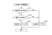
- the radar further includes a radar that specifies the position of an object around the vehicle, and the calibration unit is assumed to be a target that is estimated and estimated to have a stable temperature of the infrared camera. Calibration is performed when the distance to the vehicle is within a predetermined distance.
- the present invention it is possible to calibrate the output of the infrared camera when the preceding vehicle is close and it is difficult to image the periphery of the vehicle with the infrared camera.
- the estimating means estimates that the temperature of the infrared camera is stable when the vehicle travels at a predetermined speed or higher for a predetermined time or longer.
- the output of the infrared camera can be calibrated under a condition where the temperature of the infrared camera is stable, that is, suitable for calibration.
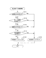
- the determination means is less likely that the driver is looking at the display means when the vehicle is turning or immediately after turning, or is in a state of rapid acceleration or sudden deceleration. to decide.
- the estimating means estimates whether or not the temperature of the infrared camera is stable according to the temperature change amount of the infrared camera from the previous calibration to the present.
- the calibration of the infrared camera is suppressed, and when the temperature change amount is large, the calibration is performed immediately. It becomes possible to perform quicker and more appropriate calibration.
- the calibration means does not perform the calibration when the predetermined living body detected based on the image data captured by the infrared camera and the vehicle are in a predetermined positional relationship.
- the calibration means determines the calibration timing based on navigation information from the navigation device.
- the calibration timing is delayed until the location passes, or the calibration is completed so that the calibration ends before the passage. It is possible to take measures such as advancing the timing.
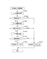
- FIG. 1 It is a block diagram which shows the structure of the vehicle periphery monitoring apparatus according to one Example of this invention. It is a figure which shows the processing flow performed by the control apparatus according to one Example of this invention. It is a figure which shows the confirmation flow of the calibration conditions 1. FIG. It is a figure which shows the confirmation flow of the calibration conditions 2. FIG. It is a figure for demonstrating the method to determine the presence or absence of the temperature stability of an infrared camera. It is a figure which shows the processing flow performed by the control apparatus according to one Example of this invention. It is a figure which shows the confirmation flow of the calibration conditions 0. FIG.
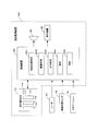
- FIG. 1 is a block diagram showing a configuration of a vehicle periphery monitoring device according to an embodiment of the present invention.
- the periphery monitoring device 100 is mounted on a vehicle and includes an infrared camera 10 that images the periphery of the vehicle, a control device 20, a speaker 30, and a display device 40.
- the infrared camera 10 includes an infrared detector 101 such as a microbolometer that detects infrared rays, an optical system 102 including a lens that forms an infrared ray emitted from a subject on the infrared detector 101, a shutter 103, and a temperature sensor. 104.
- the infrared detector 101 is a two-dimensional area sensor having pixels arranged two-dimensionally.
- the shutter 103 is configured to open and close at a timing controlled by the control device 20, and blocks infrared rays incident on the optical system 102 from the subject when in the closed state.
- the shutter 103 is preferably a flat plate whose surface temperature is uniformly distributed.
- the temperature sensor 104 detects the temperature inside the infrared camera 10 and sends a detection signal to the control device 20.
- the control device 20 is also called an electronic control unit (hereinafter referred to as “ECU”), and is a computer including a central processing unit (CPU) and a memory.
- the control device 20 is roughly divided into (i) an image processing function for detecting an object around the vehicle based on image data captured by the infrared camera 10, and (ii) the infrared camera 10 and the vehicle. It has two functions of receiving various signals from the radar 12, the vehicle state sensor 14, and the navigation device 16 and performing various controls.
- the radar 12 is, for example, a scanning laser radar, and receives the reflected light from the object of the beam scanned in each direction, thereby measuring the position of the object in each direction and the distance to it as a detection point.
- the vehicle state sensor 14 is described as a general term for a plurality of sensors that detect the state of the host vehicle as various parameters.
- the vehicle state sensor 14 includes, for example, a vehicle speed sensor that detects the speed of the host vehicle, an acceleration sensor, a brake sensor that detects the degree of depression of the brake, a yaw rate sensor that detects a yaw rate (a change speed of the rotation angle in the turning direction), and the like. Including.
- Each block in the control device 20 in FIG. 1 indicates each function (configuration) executed by the control device 20. That is, the control device 20 in FIG. 1 receives the signal from the radar 12 and the object position specifying means 201 for specifying the position (distance) of the object around the vehicle and the image around the vehicle captured by the infrared camera 10.
- An image acquisition unit 202 that acquires a gray scale image, a calibration unit 203 that calibrates the output between pixels of the infrared detector 101 of the infrared camera 10 based on image data obtained by imaging the surface of the shutter 103 by the infrared camera 10; It functions as an estimation unit 204 that estimates whether or not the temperature of the infrared camera 10 is stable, and a determination unit 205 that determines whether the driver is looking at the display unit 40 from the behavior of the vehicle.
- each block is realized by a computer (CPU) included in the control device 20.
- the configuration of the control device 20 may be incorporated in the navigation device 16.
- the control device 20 includes, for example, an A / D conversion circuit that converts an input analog signal into a digital signal, an image memory that stores a digitized image signal, and a central processing unit (CPU) that performs various arithmetic processes. , RAM used by the CPU to store data for calculation, ROM to store programs executed by the CPU and data to be used (including tables and maps), drive signals for the speaker 30, display signals for the display device 40, etc. Output circuit. The output signals of the radar 12 and the infrared camera 10 are converted into digital signals and input to the CPU.
- an A / D conversion circuit that converts an input analog signal into a digital signal
- an image memory that stores a digitized image signal
- CPU central processing unit
- Speaker 30 generates an alarm by sound or voice based on the detection result of a predetermined object (such as a pedestrian) in control device 20.
- the display device 40 displays an image obtained through imaging by the infrared camera 10 and displays for the driver to recognize an object around the vehicle. In addition, you may utilize the applicable function with which the navigation apparatus 16 is provided as the speaker 30 and the display apparatus 40.
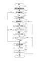
- FIG. 2 is a processing flow executed by the control device 20.
- This processing flow is a control flow for calibrating the output between pixels of the infrared detector 101 of the infrared camera 10, and the CPU of the control device 20 calls a processing program stored in the memory to set a predetermined time interval. Is executed.
- step S10 vehicle driving information is acquired.
- the vehicle driving information includes vehicle travel time, vehicle speed change history, and the like.
- step S11 it is determined whether or not the temperature of the infrared camera 10 is stable from the acquired driving information of the vehicle. If this determination is No, the process proceeds to shutter control in step S18 and calibration is started. This is because when the temperature of the infrared camera 10 is not stable, it is preferable to perform calibration so that an appropriate camera image can be acquired.
- FIG. 5 is a diagram for explaining an example of the determination method.
- the vehicle speed B and the temperature A of the infrared camera when the engine starts at time 0 starts running at time T1, stops at time T2, and starts idling again at time T3. It shows a change.
- the temperature A of the infrared camera rises during idling after the vehicle engine is started, decreases with traveling after time T1, and becomes stable with subsequent constant speed traveling.
- temperature A is stable, and temperature A rises again after the start of idling at time T3.
- From the relationship between the vehicle speed B in FIG. 5 and the temperature A of the infrared camera for example, when the temperature of the infrared camera is stable when the vehicle is decelerated after traveling at a constant speed as in section C or immediately after the vehicle stops. Can be judged (estimated).
- step S12 information (position, distance) of the object around the vehicle detected by the radar 12 is acquired in step S12.
- step S13 it is determined from the acquired information on objects around the vehicle whether there are a large number of objects such as vehicles or people ahead, that is, at least a predetermined number or more. If the determination is Yes, the process ends. This is to prevent a situation in which an acquired image of a peripheral object cannot be confirmed by calibration in a situation where the necessity for peripheral monitoring is high.
- step S13 If the determination in step S13 is No, the calibration condition 1 is confirmed in step S14.
- FIG. 3 is a diagram showing a confirmation flow of the calibration condition 1.
- FIG. 4 is a diagram showing a confirmation flow of the calibration condition 2.
- step S18 in order to perform calibration, the shutter 103 of the infrared camera 10 is controlled to be closed, and the infrared rays incident on the optical system 102 from the subject are blocked.
- step S19 the infrared camera 10 images the surface of the shutter 103.
- step S20 the output of the infrared camera 10 when the surface of the shutter 103 is imaged is calibrated. Specifically, when the surface temperature of the shutter 103 is a uniformly distributed flat plate shape, each pixel is arranged so that a uniform detection signal can be obtained from each pixel of the two-dimensional arrangement of the infrared detector 101 of the infrared camera 10. Alternatively, the signal amplification factor (gain) or the like for each predetermined pixel region (line, area) is adjusted. This adjustment (calibration) method can be performed by any conventional method.
- FIG. 6 is another example of the processing flow executed by the control device 20. 6 mainly differs from the flow of FIG. 2 in that three steps S102 to S104 are adopted in FIG. 6 instead of the three steps S11 to S13 of FIG. Further, the contents of the steps S105 to S111 in FIG. 6, that is, the confirmation of the calibration conditions 1 and 2 and the shutter control and calibration are basically the same as the contents of the corresponding steps S14 to S20 in FIG. It is the same.
- FIG. 7 is a diagram showing a confirmation flow of calibration condition 0.
- step S1021 information (position, distance) of objects around the vehicle detected by the radar 12 is acquired.
- step S1022 it is determined from the acquired information on objects around the vehicle whether there are a large number of objects such as vehicles and people ahead, that is, at least a predetermined number or more.
- step S1025 information on the preceding vehicle, traffic congestion information, road information, and the like are acquired via the navigation device 16.
- step S103 it is determined whether or not the calibration condition 0 is cleared in step S103.
- step S109 When the absolute value of the temperature change amount ⁇ T is larger than the predetermined large threshold value ⁇ TL ( ⁇ T> ⁇ TL), the process proceeds to step S109 and calibration is performed immediately. This is because when the temperature change amount of the infrared camera 10 is particularly large, it is better to perform calibration early.
- the absolute value of the temperature change amount ⁇ T is smaller than a predetermined small threshold value ⁇ TS ( ⁇ T ⁇ TS)
- the process proceeds to step S112 and the calibration condition 1 is confirmed.
- the confirmation of the calibration condition 1 is the flow already described with reference to FIG.
- the calibration conditions 1 and the calibration conditions in steps S105 to S108 Proceed to step 2 for confirmation.
- the confirmation of steps 105 to S108 is the same as steps S14 to S17 of FIG. 2 already described.
- step S106 and S113 in FIG. 6 If calibration condition 1 is not cleared (No) in steps S106 and S113 in FIG. 6, or if calibration condition 2 is cleared (Yes) in S108, the process proceeds to steps S109 to S111, and the shutter 104 of the infrared camera 10 is set. Control (close) and calibrate. This calibration is the same as steps S18 to S20 in FIG. If calibration condition 1 is cleared (Yes) in step S113, or if calibration condition 2 is not cleared (No) in S108, the process ends.
- calibration sinutter control
- the infrared camera is performed in a state in which the temperature of the infrared camera is stable and at a timing that does not interfere with driving of the vehicle, particularly surrounding monitoring by the driver. Therefore, the calibration can be performed efficiently with high accuracy and at an appropriate timing.
- the present invention is not limited to such embodiments, and can be modified and used without departing from the spirit of the present invention.
- the present invention can also be applied to a millimeter wave radar or the like.
Landscapes
- Engineering & Computer Science (AREA)
- Physics & Mathematics (AREA)
- General Physics & Mathematics (AREA)
- Multimedia (AREA)
- Signal Processing (AREA)
- Radar, Positioning & Navigation (AREA)
- Remote Sensing (AREA)
- Computer Networks & Wireless Communication (AREA)
- Electromagnetism (AREA)
- Traffic Control Systems (AREA)
- Closed-Circuit Television Systems (AREA)
Abstract
Description
20 制御装置
30 スピーカ
40 表示装置
100 周辺監視装置
Claims (7)
- 車両に搭載され、該車両の周辺を撮像する赤外線カメラと、
前記赤外線カメラが撮像した画像データに基づく表示画像を生成して表示する表示手段と、
前記赤外線カメラへ入光させる開口を開閉するシャッターの表面を撮像した画像データに基づいて、前記赤外線カメラの画素間の出力を校正する校正手段と、
前記赤外線カメラの温度の安定の有無を推定する推定手段と、
車両の挙動から運転者が前記表示手段を見ている可能性を判断する判断手段とを備え、
前記校正手段は、前記赤外線カメラの温度が安定していると推定され、かつ運転者が前記表示手段を見ている可能性が低いと判断される場合に、前記校正をおこなう、車両の周辺監視装置。 - 前記車両の周辺の対象物の位置を特定するレーダをさらに備え、
前記校正手段は、前記赤外線カメラの温度が安定していると推定され、かつ特定された対象物である前走車までの距離が所定の距離以内である場合に、前記校正をおこなう、請求項1に記載の車両の周辺監視装置。 - 前記推定手段は、前記車両が所定速度以上で所定時間以上走行したときに前記赤外線カメラの温度が安定していると推定する、請求項1または2に記載の周辺監視装置。
- 前記判断手段は、前記車両が旋回中あるいは旋回直後であるとき、または急加速あるいは急減速の状態にあるときに、運転者が前記表示手段を見ている可能性が低いと判断する、請求項1~3のいずれかに記載の周辺監視装置。
- 前記推定手段は、前回の校正時から現在までの前記赤外線カメラの温度変化量に応じて当該赤外線カメラの温度の安定の有無を推定する、請求項1に記載の周辺監視装置。
- 前記校正手段は、前記赤外線カメラが撮像した画像データに基づいて検知された所定の生体と前記車両とが所定の位置関係にあるときには前記校正をおこなわない、請求項1に記載の周辺監視装置。
- 前記校正手段は、ナビゲーション装置からのナビゲーション情報に基づいて前記校正のタイミングを決定する、請求項1に記載の周辺監視装置。
Priority Applications (4)
| Application Number | Priority Date | Filing Date | Title |
|---|---|---|---|
| EP11755817.1A EP2533226A4 (en) | 2010-03-17 | 2011-02-21 | DEVICE FOR MONITORING VEHICLE ENVIRONMENTS |
| US13/583,714 US9123247B2 (en) | 2010-03-17 | 2011-02-21 | Surrounding area monitoring apparatus for vehicle |
| JP2012505470A JP5503730B2 (ja) | 2010-03-17 | 2011-02-21 | 車両の周辺監視装置 |
| CN201180012349.1A CN103098110B (zh) | 2010-03-17 | 2011-02-21 | 车辆周围监测装置 |
Applications Claiming Priority (2)
| Application Number | Priority Date | Filing Date | Title |
|---|---|---|---|
| JP2010060431 | 2010-03-17 | ||
| JP2010-060431 | 2010-03-17 |
Publications (1)
| Publication Number | Publication Date |
|---|---|
| WO2011114624A1 true WO2011114624A1 (ja) | 2011-09-22 |
Family
ID=44648740
Family Applications (1)
| Application Number | Title | Priority Date | Filing Date |
|---|---|---|---|
| PCT/JP2011/000960 Ceased WO2011114624A1 (ja) | 2010-03-17 | 2011-02-21 | 車両の周辺監視装置 |
Country Status (5)
| Country | Link |
|---|---|
| US (1) | US9123247B2 (ja) |
| EP (1) | EP2533226A4 (ja) |
| JP (1) | JP5503730B2 (ja) |
| CN (1) | CN103098110B (ja) |
| WO (1) | WO2011114624A1 (ja) |
Cited By (5)
| Publication number | Priority date | Publication date | Assignee | Title |
|---|---|---|---|---|
| WO2013131683A1 (de) * | 2012-03-05 | 2013-09-12 | Robert Bosch Gmbh | Infrarotsensor mit beschleunigungssensor und verfahren zum betreiben eines infrarotsensors |
| JP2014178836A (ja) * | 2013-03-14 | 2014-09-25 | Fuji Heavy Ind Ltd | 車両の外部環境認識装置 |
| WO2018142687A1 (ja) * | 2017-01-31 | 2018-08-09 | 株式会社Jvcケンウッド | 熱画像処理装置、赤外線撮像装置、熱画像処理方法、及び熱画像処理プログラム |
| WO2020162498A1 (ja) * | 2019-02-06 | 2020-08-13 | 株式会社デンソー | 情報処理装置 |
| KR20220087596A (ko) * | 2020-12-17 | 2022-06-27 | 주식회사 콕스 | 열상 카메라를 구비한 체온 측정장치에 의한 체온 측정 방법 |
Families Citing this family (25)
| Publication number | Priority date | Publication date | Assignee | Title |
|---|---|---|---|---|
| US9208542B2 (en) | 2009-03-02 | 2015-12-08 | Flir Systems, Inc. | Pixel-wise noise reduction in thermal images |
| WO2012170946A2 (en) | 2011-06-10 | 2012-12-13 | Flir Systems, Inc. | Low power and small form factor infrared imaging |
| US9843742B2 (en) | 2009-03-02 | 2017-12-12 | Flir Systems, Inc. | Thermal image frame capture using de-aligned sensor array |
| US9235876B2 (en) | 2009-03-02 | 2016-01-12 | Flir Systems, Inc. | Row and column noise reduction in thermal images |
| US10091439B2 (en) | 2009-06-03 | 2018-10-02 | Flir Systems, Inc. | Imager with array of multiple infrared imaging modules |
| US9143703B2 (en) | 2011-06-10 | 2015-09-22 | Flir Systems, Inc. | Infrared camera calibration techniques |
| CN103875235B (zh) | 2011-06-10 | 2018-10-12 | 菲力尔系统公司 | 用于红外成像装置的非均匀性校正技术 |
| KR102001659B1 (ko) * | 2012-11-19 | 2019-07-19 | 한국전자통신연구원 | 차량용 카메라 캘리브레이션 장치 및 방법 |
| CN205160655U (zh) * | 2012-12-21 | 2016-04-13 | 菲力尔系统公司 | 用于交通工具的红外成像系统 |
| DE102013208763A1 (de) * | 2013-05-13 | 2014-11-13 | Robert Bosch Gmbh | Verfahren und Vorrichtung zum Erkennen einer Anfahrabsicht eines haltenden Fahrzeugs |
| BR112015029578B1 (pt) * | 2013-05-31 | 2021-12-14 | Toyota Jidosha Kabushiki Kaisha | Aparelho de auxílio à direção de veículo e computador de bordo |
| US20210163013A1 (en) * | 2016-10-25 | 2021-06-03 | Mitsubishi Electric Corporation | Peripheral-information determining apparatus |
| CN108093155A (zh) * | 2016-11-20 | 2018-05-29 | 天津嘉美易科科技发展有限公司 | 一种远程会议服务用摄像头 |
| US11113791B2 (en) | 2017-01-03 | 2021-09-07 | Flir Systems, Inc. | Image noise reduction using spectral transforms |
| JP6846624B2 (ja) * | 2017-02-23 | 2021-03-24 | パナソニックIpマネジメント株式会社 | 画像表示システム、画像表示方法及びプログラム |
| CN107284355B (zh) * | 2017-06-16 | 2019-05-03 | 长安大学 | 一种安全车门开启处理方法及系统 |
| CN107450073A (zh) * | 2017-08-31 | 2017-12-08 | 上海航盛实业有限公司 | 一种毫米波雷达 |
| JP6927914B2 (ja) * | 2018-03-28 | 2021-09-01 | 京セラ株式会社 | 画像処理装置、撮像装置、および移動体 |
| CN108924426B (zh) * | 2018-08-01 | 2020-01-10 | Oppo广东移动通信有限公司 | 图像处理方法和装置、电子设备、计算机可读存储介质 |
| WO2020024575A1 (zh) * | 2018-08-01 | 2020-02-06 | Oppo广东移动通信有限公司 | 图像处理方法和装置、电子设备、计算机可读存储介质 |
| CN109120846B (zh) * | 2018-08-01 | 2020-01-10 | Oppo广东移动通信有限公司 | 图像处理方法和装置、电子设备、计算机可读存储介质 |
| CN111579080B (zh) * | 2020-04-30 | 2021-09-14 | 沈阳天眼智云信息科技有限公司 | 红外热像体温监测仪的自校准方法 |
| CN112071100B (zh) * | 2020-09-21 | 2021-10-12 | 安徽省萧县黄河故道园艺场 | 一种交通信号防遮挡多功能装置 |
| CN113043987A (zh) * | 2020-11-16 | 2021-06-29 | 泰州镭昇光电科技有限公司 | 基于货车检测的防爆膜状态切换系统 |
| JP2023074749A (ja) * | 2021-11-18 | 2023-05-30 | 株式会社Jvcケンウッド | 制御システムおよび制御方法 |
Citations (6)
| Publication number | Priority date | Publication date | Assignee | Title |
|---|---|---|---|---|
| JPH0416022B2 (ja) | 1983-07-06 | 1992-03-19 | Fujitsu Ltd | |
| JPH08240831A (ja) * | 1995-03-02 | 1996-09-17 | Canon Inc | ぶれ補正装置 |
| JP2001153723A (ja) * | 1999-11-30 | 2001-06-08 | Nec Corp | 赤外線撮像装置及びそれに用いる信号処理方法 |
| US20030057371A1 (en) * | 2000-12-26 | 2003-03-27 | Wood Roland Andrew | Lightweight infrared camera |
| JP2007336288A (ja) * | 2006-06-15 | 2007-12-27 | Sumitomo Electric Ind Ltd | 障害物検出システム及び障害物検出方法 |
| JP2008187254A (ja) * | 2007-01-26 | 2008-08-14 | Sumitomo Electric Ind Ltd | 赤外撮像装置、撮像素子の出力値算出方法 |
Family Cites Families (13)
| Publication number | Priority date | Publication date | Assignee | Title |
|---|---|---|---|---|
| US6856873B2 (en) * | 1995-06-07 | 2005-02-15 | Automotive Technologies International, Inc. | Vehicular monitoring systems using image processing |
| US6023061A (en) * | 1995-12-04 | 2000-02-08 | Microcam Corporation | Miniature infrared camera |
| JPH10313428A (ja) | 1997-05-13 | 1998-11-24 | Sony Corp | 固体撮像素子の固定パターンノイズ除去方法と、固定パターンノイズ除去装置 |
| EP1160550A4 (en) * | 1999-01-14 | 2008-01-30 | Matsushita Electric Industrial Co Ltd | INFRARED IMAGING APPARATUS, A VEHICLE EQUIPPED THEREWITH, AND DEVICE FOR ADJUSTING AN INFRARED IMAGE |
| JP4016022B2 (ja) | 1999-01-14 | 2007-12-05 | 松下電器産業株式会社 | 赤外線画像撮像装置およびこれを搭載した車両 |
| JP3565338B2 (ja) | 2001-04-11 | 2004-09-15 | 日本電気株式会社 | 赤外線撮像装置及びドリフト補正方法 |
| US6707044B2 (en) * | 2001-05-07 | 2004-03-16 | Flir Systems Ab | Infrared camera system |
| DE10207039A1 (de) * | 2002-02-20 | 2003-09-04 | Bayerische Motoren Werke Ag | Verfahren und Vorrichtung zur Sichtbarmachung eines Ausschnitts der Umgebung eines Fahrzeugs sowie eine Kalibriervorrichtung zur Kalibrierung der Vorrichtung |
| DE10348109A1 (de) * | 2003-10-16 | 2005-05-19 | Bayerische Motoren Werke Ag | Verfahren und Vorrichtung zur Sichtbarmachung einer Fahrzeugumgebung |
| JP4193765B2 (ja) * | 2004-01-28 | 2008-12-10 | トヨタ自動車株式会社 | 車両用走行支援装置 |
| DE102006038423A1 (de) * | 2006-08-17 | 2008-02-21 | Bayerische Motoren Werke Ag | Vorrichtung zur Kalibrierung einer optischen Kamera und/oder einer Infrarot-Kamera |
| US8478480B2 (en) * | 2006-10-27 | 2013-07-02 | International Electronic Machines Corp. | Vehicle evaluation using infrared data |
| US8502860B2 (en) * | 2009-09-29 | 2013-08-06 | Toyota Motor Engineering & Manufacturing North America (Tema) | Electronic control system, electronic control unit and associated methodology of adapting 3D panoramic views of vehicle surroundings by predicting driver intent |
-
2011
- 2011-02-21 WO PCT/JP2011/000960 patent/WO2011114624A1/ja not_active Ceased
- 2011-02-21 CN CN201180012349.1A patent/CN103098110B/zh not_active Expired - Fee Related
- 2011-02-21 EP EP11755817.1A patent/EP2533226A4/en not_active Withdrawn
- 2011-02-21 JP JP2012505470A patent/JP5503730B2/ja not_active Expired - Fee Related
- 2011-02-21 US US13/583,714 patent/US9123247B2/en active Active
Patent Citations (6)
| Publication number | Priority date | Publication date | Assignee | Title |
|---|---|---|---|---|
| JPH0416022B2 (ja) | 1983-07-06 | 1992-03-19 | Fujitsu Ltd | |
| JPH08240831A (ja) * | 1995-03-02 | 1996-09-17 | Canon Inc | ぶれ補正装置 |
| JP2001153723A (ja) * | 1999-11-30 | 2001-06-08 | Nec Corp | 赤外線撮像装置及びそれに用いる信号処理方法 |
| US20030057371A1 (en) * | 2000-12-26 | 2003-03-27 | Wood Roland Andrew | Lightweight infrared camera |
| JP2007336288A (ja) * | 2006-06-15 | 2007-12-27 | Sumitomo Electric Ind Ltd | 障害物検出システム及び障害物検出方法 |
| JP2008187254A (ja) * | 2007-01-26 | 2008-08-14 | Sumitomo Electric Ind Ltd | 赤外撮像装置、撮像素子の出力値算出方法 |
Non-Patent Citations (1)
| Title |
|---|
| See also references of EP2533226A4 |
Cited By (15)
| Publication number | Priority date | Publication date | Assignee | Title |
|---|---|---|---|---|
| WO2013131683A1 (de) * | 2012-03-05 | 2013-09-12 | Robert Bosch Gmbh | Infrarotsensor mit beschleunigungssensor und verfahren zum betreiben eines infrarotsensors |
| CN104145476A (zh) * | 2012-03-05 | 2014-11-12 | 罗伯特·博世有限公司 | 具有加速度传感器的红外传感器以及用于运行红外传感器的方法 |
| JP2015515608A (ja) * | 2012-03-05 | 2015-05-28 | ローベルト ボツシユ ゲゼルシヤフト ミツト ベシユレンクテル ハフツングRobert Bosch Gmbh | 加速度センサを備えた赤外線センサ及び該赤外線センサの動作方法 |
| US9476762B2 (en) | 2012-03-05 | 2016-10-25 | Robert Bosch Gmbh | Infrared sensor with acceleration sensor and method for operating an infrared sensor |
| JP2014178836A (ja) * | 2013-03-14 | 2014-09-25 | Fuji Heavy Ind Ltd | 車両の外部環境認識装置 |
| JP2018125639A (ja) * | 2017-01-31 | 2018-08-09 | 株式会社Jvcケンウッド | 熱画像処理装置、赤外線撮像装置、熱画像処理方法、及び熱画像処理プログラム |
| WO2018142687A1 (ja) * | 2017-01-31 | 2018-08-09 | 株式会社Jvcケンウッド | 熱画像処理装置、赤外線撮像装置、熱画像処理方法、及び熱画像処理プログラム |
| CN109644237A (zh) * | 2017-01-31 | 2019-04-16 | Jvc 建伍株式会社 | 热图像处理装置、红外线拍摄装置、热图像处理方法以及热图像处理程序 |
| US10769816B2 (en) | 2017-01-31 | 2020-09-08 | Jvckenwood Corporation | Thermal image processing device, infrared imaging apparatus, thermal image processing method, and thermal image processing program |
| CN109644237B (zh) * | 2017-01-31 | 2020-09-29 | Jvc 建伍株式会社 | 热图像处理装置和方法、红外线拍摄装置以及存储介质 |
| WO2020162498A1 (ja) * | 2019-02-06 | 2020-08-13 | 株式会社デンソー | 情報処理装置 |
| JP2020127164A (ja) * | 2019-02-06 | 2020-08-20 | 株式会社デンソー | 情報処理装置 |
| JP7263807B2 (ja) | 2019-02-06 | 2023-04-25 | 株式会社デンソー | 情報処理装置 |
| KR20220087596A (ko) * | 2020-12-17 | 2022-06-27 | 주식회사 콕스 | 열상 카메라를 구비한 체온 측정장치에 의한 체온 측정 방법 |
| KR102580362B1 (ko) * | 2020-12-17 | 2023-09-21 | 주식회사 콕스 | 열상 카메라를 구비한 체온 측정장치에 의한 체온 측정 방법 |
Also Published As
| Publication number | Publication date |
|---|---|
| CN103098110B (zh) | 2015-04-15 |
| JPWO2011114624A1 (ja) | 2013-06-27 |
| EP2533226A4 (en) | 2014-01-22 |
| EP2533226A1 (en) | 2012-12-12 |
| US20130002874A1 (en) | 2013-01-03 |
| JP5503730B2 (ja) | 2014-05-28 |
| US9123247B2 (en) | 2015-09-01 |
| CN103098110A (zh) | 2013-05-08 |
Similar Documents
| Publication | Publication Date | Title |
|---|---|---|
| JP5503730B2 (ja) | 車両の周辺監視装置 | |
| JP5387531B2 (ja) | 走行支援装置 | |
| JP5012718B2 (ja) | 画像処理装置 | |
| JP5600332B2 (ja) | 運転支援装置 | |
| JP6137081B2 (ja) | 車載機器 | |
| US10769816B2 (en) | Thermal image processing device, infrared imaging apparatus, thermal image processing method, and thermal image processing program | |
| JP6330160B2 (ja) | 物体認識装置 | |
| US20220024452A1 (en) | Image processing apparatus, imaging apparatus, moveable body, and image processing method | |
| JP2007172035A (ja) | 車載画像認識装置、車載撮像装置、車載撮像制御装置、警告処理装置、画像認識方法、撮像方法および撮像制御方法 | |
| WO2014024284A1 (ja) | 衝突予測装置 | |
| JP2014187496A (ja) | 故障検出装置 | |
| JP6429360B2 (ja) | 物体検出装置 | |
| US20220126819A1 (en) | Vehicle control apparatus and control method therefor | |
| JP4470070B2 (ja) | 車両周辺監視装置、車両、車両周辺監視用プログラム | |
| US11794536B2 (en) | Vehicle control system and vehicle control method for determining chance of collision | |
| JP5717416B2 (ja) | 運転支援制御装置 | |
| US20240355126A1 (en) | Signal processing device, signal processing system, signal processing method, and program | |
| US12179666B2 (en) | Driver assistance apparatus, a vehicle, and a method of controlling a vehicle | |
| JP4760100B2 (ja) | 画像処理装置及びこれを用いる車両用運転支援装置 | |
| JP2007174113A (ja) | 障害物検出システム及び障害物検出方法 | |
| JP4869835B2 (ja) | 車両周辺監視システム | |
| JP4590654B2 (ja) | 車両周辺監視装置、車両、車両周辺監視プログラム | |
| KR20170052857A (ko) | 운전지원장치 및 운전지원방법 | |
| JP2005297648A (ja) | 物体検出装置、車両制御システム | |
| JP2025105189A (ja) | 判定装置、判定方法および判定プログラム |
Legal Events
| Date | Code | Title | Description |
|---|---|---|---|
| WWE | Wipo information: entry into national phase |
Ref document number: 201180012349.1 Country of ref document: CN |
|
| 121 | Ep: the epo has been informed by wipo that ep was designated in this application |
Ref document number: 11755817 Country of ref document: EP Kind code of ref document: A1 |
|
| WWE | Wipo information: entry into national phase |
Ref document number: 2012505470 Country of ref document: JP |
|
| WWE | Wipo information: entry into national phase |
Ref document number: 2011755817 Country of ref document: EP |
|
| WWE | Wipo information: entry into national phase |
Ref document number: 13583714 Country of ref document: US |
|
| NENP | Non-entry into the national phase |
Ref country code: DE |