WO2011114932A1 - 音声処理装置、音声処理方法、およびプログラム - Google Patents
音声処理装置、音声処理方法、およびプログラム Download PDFInfo
- Publication number
- WO2011114932A1 WO2011114932A1 PCT/JP2011/055293 JP2011055293W WO2011114932A1 WO 2011114932 A1 WO2011114932 A1 WO 2011114932A1 JP 2011055293 W JP2011055293 W JP 2011055293W WO 2011114932 A1 WO2011114932 A1 WO 2011114932A1
- Authority
- WO
- WIPO (PCT)
- Prior art keywords
- signal
- unit
- frequency
- time domain
- channels
- Prior art date
- Legal status (The legal status is an assumption and is not a legal conclusion. Google has not performed a legal analysis and makes no representation as to the accuracy of the status listed.)
- Ceased
Links
Images









Classifications
-
- G—PHYSICS
- G10—MUSICAL INSTRUMENTS; ACOUSTICS
- G10L—SPEECH ANALYSIS TECHNIQUES OR SPEECH SYNTHESIS; SPEECH RECOGNITION; SPEECH OR VOICE PROCESSING TECHNIQUES; SPEECH OR AUDIO CODING OR DECODING
- G10L19/00—Speech or audio signals analysis-synthesis techniques for redundancy reduction, e.g. in vocoders; Coding or decoding of speech or audio signals, using source filter models or psychoacoustic analysis
- G10L19/008—Multichannel audio signal coding or decoding using interchannel correlation to reduce redundancy, e.g. joint-stereo, intensity-coding or matrixing
-
- G—PHYSICS
- G10—MUSICAL INSTRUMENTS; ACOUSTICS
- G10L—SPEECH ANALYSIS TECHNIQUES OR SPEECH SYNTHESIS; SPEECH RECOGNITION; SPEECH OR VOICE PROCESSING TECHNIQUES; SPEECH OR AUDIO CODING OR DECODING
- G10L19/00—Speech or audio signals analysis-synthesis techniques for redundancy reduction, e.g. in vocoders; Coding or decoding of speech or audio signals, using source filter models or psychoacoustic analysis
- G10L19/02—Speech or audio signals analysis-synthesis techniques for redundancy reduction, e.g. in vocoders; Coding or decoding of speech or audio signals, using source filter models or psychoacoustic analysis using spectral analysis, e.g. transform vocoders or subband vocoders
- G10L19/0212—Speech or audio signals analysis-synthesis techniques for redundancy reduction, e.g. in vocoders; Coding or decoding of speech or audio signals, using source filter models or psychoacoustic analysis using spectral analysis, e.g. transform vocoders or subband vocoders using orthogonal transformation
Definitions
- the present invention relates to an audio processing device, an audio processing method, and a program, and in particular, when a multi-channel audio signal is downmixed and encoded, increases the delay and the amount of calculation when decoding the audio signal.
- the present invention relates to a voice processing device, a voice processing method, and a program that can be suppressed.
- An encoding device that encodes a multi-channel audio signal can perform highly efficient encoding by performing encoding using the relationship between channels. Examples of such encoding include intensity encoding, M / S stereo encoding, and spatial encoding.
- An encoding apparatus that performs spatial encoding downmixes an n-channel audio signal into an m-channel (m ⁇ n) audio signal and encodes it, and obtains a spatial parameter that represents the relationship between the channels during the downmix. The spatial parameter is transmitted together with the encoded data.
- a decoding device that receives the spatial parameter and the encoded data decodes the encoded data, and restores the original n-channel audio signal from the m-channel audio signal obtained as a result of the decoding, using the spatial parameter.
- BC parameters Spatial parameters
- ILD Inter-channel Level Difference
- IPD Inter-channel Phase Difference
- ICC Inter-channel Correlation
- the ILD is a parameter indicating a ratio of signal sizes between channels.
- IPD is a parameter indicating a phase difference between channels
- ICC is a parameter indicating a correlation between channels.
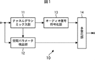
- FIG. 1 is a block diagram illustrating a configuration example of an encoding device that performs spatial encoding.
- the audio signal to be encoded is a stereo audio signal (hereinafter referred to as a stereo signal), and the encoded data obtained as a result of encoding is encoded data of a monaural audio signal (hereinafter referred to as a monaural signal). .
- the encoding apparatus 10 in FIG. 1 includes a channel downmix unit 11, a spatial parameter detection unit 12, an audio signal encoding unit 13, and a multiplexing unit 14.
- the encoding apparatus 10 the stereo signal consisting of audio signals X L and the audio signal X R for right for left is input as coded, coding device 10 outputs the encoded data of monaural signal.
- the channel downmixing unit 11 of the encoding device 10 downmixing a stereo signal input as coded into a monaural signal X M. Then, the channel downmix unit 11 supplies the monaural signal to the spatial parameter detection unit 12 and the audio signal encoding unit 13.
- Spatial parameter detection unit 12 a monaural signal X M supplied from the channel downmixing unit 11, based on the stereo signal input as coded detects BC parameters, supplied to the multiplexer 14.
- the audio signal encoding unit 13 encodes the monaural signal supplied from the channel downmix unit 11 and supplies the encoded data obtained as a result to the multiplexing unit 14.
- the multiplexing unit 14 multiplexes the encoded data supplied from the audio signal encoding unit 13 and the BC parameter supplied from the spatial parameter detection unit 12 and outputs the multiplexed data.
- FIG. 2 is a block diagram showing a configuration example of the audio signal encoding unit 13 of FIG.
- the configuration of the audio signal encoding unit 13 in FIG. 2 is performed when the audio signal encoding unit 13 performs encoding using, for example, an MPEG-2 AAC LC (Moving Picture Experts Group phase 2 Advanced Audio Coding Low Complexity) profile scheme. It is a configuration. However, in order to simplify the description, the configuration is simplified in FIG.
- the audio signal encoding unit 13 in FIG. 2 includes an MDCT (Modified Discrete Cosine Transform) unit 21, a spectrum quantization unit 22, an entropy encoding unit 23, and a multiplexing unit 24.
- MDCT Modified Discrete Cosine Transform
- the MDCT unit 21 performs MDCT on the monaural signal supplied from the channel downmix unit 11, and converts the monaural signal, which is a time domain signal, into MDCT coefficients, which are frequency domain coefficients.
- the MDCT unit 21 supplies the MDCT coefficient obtained as a result of the conversion to the spectrum quantization unit 22 as a frequency spectrum coefficient.
- the spectrum quantization unit 22 quantizes the frequency spectrum coefficient supplied from the MDCT unit 21 and supplies it to the entropy encoding unit 23. Further, the spectrum quantization unit 22 supplies quantization information, which is information related to the quantization, to the multiplexing unit 24. Quantization information includes scale factor, quantization bit information, and the like.
- the entropy coding unit 23 performs entropy coding such as Huffman coding and arithmetic coding on the quantized frequency spectrum coefficient supplied from the spectrum quantization unit 22 and performs lossless compression.
- the entropy encoding unit 23 supplies data obtained as a result of entropy encoding to the multiplexing unit 24.
- the multiplexing unit 24 multiplexes the data supplied from the entropy encoding unit 23 and the quantization information supplied from the spectrum quantization unit 22, and uses the resulting data as encoded data as the multiplexing unit 14 ( 1).
- FIG. 3 is a block diagram showing another configuration example of the audio signal encoding unit 13 of FIG.
- the configuration of the audio signal encoding unit 13 in FIG. 3 is a configuration in the case where encoding is performed by a scheme such as an MPEG-2 AAC SSR (Scalable Sample Rate) profile or MP3 (MPEG Audio Layer-3). .
- a scheme such as an MPEG-2 AAC SSR (Scalable Sample Rate) profile or MP3 (MPEG Audio Layer-3).
- MP3 MPEG Audio Layer-3
- the audio signal encoding unit 13 in FIG. 3 includes an analysis filter bank 31, MDCT units 32-1 to 32-N (N is an arbitrary integer), a spectrum quantization unit 33, an entropy encoding unit 34, and a multiplexing unit 35. Consists of.
- the analysis filter bank 31 includes a QMF (Quadrature Mirror Filterbank) bank, a PQF (Poly-phase Quadrature Filter) bank, and the like.
- the analysis filter bank 31 divides the monaural signal supplied from the channel downmix unit 11 into N groups according to the frequency.
- the analysis filter bank 31 supplies the N subband signals obtained as a result of the division to the MDCT units 32-1 to 32-N, respectively.
- Each of the MDCT units 32-1 to 32-N performs MDCT on the subband signal supplied from the analysis filter bank 31, and converts the subband signal that is a time domain signal into an MDCT coefficient that is a frequency domain coefficient. To do.
- the MDCT units 32-1 to 32-N supply the MDCT coefficients of the respective subband signals to the spectrum quantization unit 33 as frequency spectrum coefficients.
- the spectrum quantization unit 33 quantizes the N frequency spectrum coefficients supplied from the MDCT units 32-1 to 32-N, and supplies the quantized values to the entropy coding unit 34. Further, the spectrum quantization unit 33 supplies the quantization information of the quantization to the multiplexing unit 35.
- the entropy coding unit 34 performs entropy coding such as Huffman coding and arithmetic coding on each of the N quantized frequency spectrum coefficients supplied from the spectrum quantization unit 33 and performs lossless compression. .
- the entropy encoding unit 34 supplies N data obtained as a result of entropy encoding to the multiplexing unit 35.
- the multiplexing unit 35 multiplexes the N pieces of data supplied from the entropy encoding unit 34 and the quantization information supplied from the spectrum quantization unit 33, and multiplexes the resulting data as encoded data. It supplies to the part 14 (FIG. 1).
- FIG. 4 is a block diagram illustrating a configuration example of a decoding device that decodes the encoded data spatially encoded by the encoding device 10 of FIG.
- the decoding device 40 decodes the encoded data supplied from the encoding device in FIG. 1 and generates a stereo signal.
- the demultiplexing unit 41 of the decoding device 40 performs demultiplexing on the multiplexed encoded data supplied from the encoding device 10 of FIG. 1, and converts the encoded data and BC parameters. obtain.
- the demultiplexer 41 supplies the encoded data to the audio signal decoder 42 and supplies the BC parameters to the generation parameter calculator 43.
- Audio signal decoding unit 42 decodes the encoded data supplied from the demultiplexer 41, and supplies the monaural signal X M is a time-domain signal obtained as a result of the stereo signal generator 44.
- the generation parameter calculation unit 43 uses the BC parameter supplied from the demultiplexing unit 41, and is a parameter for generating a stereo signal from a monaural signal that is a decoding result of encoded data multiplexed together with the BC parameter. Calculate the parameters.
- the generation parameter calculation unit 43 supplies the generation parameter to the stereo signal generation unit 44.
- the stereo signal generation unit 44 uses the generation parameter supplied from the generation parameter calculation unit 43 to generate the left audio signal X L and the right audio signal X from the monaural signal X M supplied from the audio signal decoding unit 42. R is generated. Stereo signal generation unit 44 outputs the audio signal X L and the audio signal X R for the right for the left stereo signal.
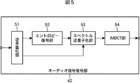
- FIG. 5 is a block diagram illustrating a configuration example of the audio signal decoding unit 42 of FIG.
- the configuration of the audio signal decoding unit 42 in FIG. 5 is a configuration in the case where encoded data encoded by, for example, the MPEG-2 AAC ⁇ LC profile method is input to the decoding device 40. That is, the audio signal decoding unit 42 in FIG. 5 decodes the encoded data encoded by the audio signal encoding unit 13 in FIG.
- the audio signal decoding unit 42 in FIG. 5 includes a demultiplexing unit 51, an entropy decoding unit 52, a spectrum dequantization unit 53, and an IMDCT unit 54.
- the demultiplexing unit 51 performs demultiplexing on the encoded data supplied from the demultiplexing unit 41 in FIG. 4 and obtains frequency spectrum coefficients and quantization information that are quantized and entropy-coded.
- the demultiplexing unit 51 supplies the quantized and entropy-encoded frequency spectrum coefficient to the entropy decoding unit 52 and supplies the quantization information to the spectrum dequantization unit 53.
- the entropy decoding unit 52 performs entropy decoding such as Huffman decoding and arithmetic decoding on the frequency spectrum coefficient supplied from the demultiplexing unit 51, and restores the quantized frequency spectrum coefficient.
- the entropy decoding unit 52 supplies the frequency spectrum coefficient to the spectrum inverse quantization unit 53.
- the spectrum dequantization unit 53 dequantizes the quantized frequency spectrum coefficient supplied from the entropy decoding unit 52 based on the quantization information supplied from the demultiplexing unit 51 to restore the frequency spectrum coefficient. . Then, the spectrum inverse quantization unit 53 supplies the frequency spectrum coefficient to an IMDCT (Inverse MDCT) (inverse corrected cosine transform) unit 54.
- IMDCT Inverse MDCT
- IMDCT unit 54 performs IMDCT on the frequency spectrum coefficients supplied from the spectrum inverse quantization unit 53, converts the frequency spectral coefficients in the mono signal X M is a time domain signal. IMDCT unit 54 supplies the monaural signal X M to the stereo signal generator 44 (FIG. 4).
- FIG. 6 is a block diagram showing another configuration example of the audio signal decoding unit 42 of FIG.
- the configuration of the audio signal decoding unit 42 in FIG. 6 is a configuration in the case where encoded data encoded by, for example, an MPEG-2 AAC SSR profile or a method such as MP3 is input to the decoding device 40. That is, the audio signal decoding unit 42 in FIG. 6 decodes the encoded data encoded by the audio signal encoding unit 13 in FIG.
- a demultiplexing unit 61 includes a demultiplexing unit 61, an entropy decoding unit 62, a spectral dequantization unit 63, IMDCT units 64-1 to 64-N, and a synthesis filter bank 65.
- the demultiplexing unit 61 demultiplexes the encoded data supplied from the demultiplexing unit 41 of FIG. 4, and frequency spectrum coefficients of the N subband signals that are quantized and entropy-coded. And get the quantization information.
- the demultiplexing unit 61 supplies the frequency spectrum coefficients of the N subband signals that have been quantized and entropy-coded to the entropy decoding unit 62, and supplies the quantization information to the spectrum dequantization unit 63.
- the entropy decoding unit 62 performs entropy decoding such as Huffman decoding and arithmetic decoding on each of the frequency spectral coefficients of the N subband signals supplied from the demultiplexing unit 61 and supplies the result to the spectral dequantization unit 63. To do.
- the spectrum inverse quantization unit 63 calculates the frequency spectrum coefficients of the N subband signals obtained as a result of entropy decoding supplied from the entropy decoding unit 62. Dequantize each. As a result, the frequency spectrum coefficients of the N subband signals are restored.
- the spectrum inverse quantization unit 63 supplies the frequency spectrum coefficients of the restored N subband signals to the IMDCT units 64-1 to 64-N one by one.
- the IMDCT units 64-1 to 64-N perform IMDCT on the frequency spectrum coefficients supplied from the spectrum inverse quantization unit 63, and convert the frequency spectrum coefficients into subband signals that are time domain signals.
- the IMDCT units 64-1 to 64-N supply the subband signals obtained as a result of the conversion to the synthesis filter bank 65, respectively.
- the synthesis filter bank 65 is composed of inverse PQF, inverse QMF, and the like. Synthesis filter bank 65 synthesizes the N sub-band signals supplied from the IMDCT unit 64-1 to 64-N, the stereo signal generator 44 (FIG. 4) a signal obtained as a result monaural signal X M Supply.
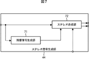
- FIG. 7 is a block diagram illustrating a configuration example of the stereo signal generation unit 44 of FIG.
- reverberation signal generation unit 71 includes a reverberation signal generation unit 71 and a stereo synthesis unit 72.
- Reverberation signal generation unit 71 using the monaural signal X M supplied from the audio signal decoding unit 42 of FIG. 4, it is this mono signal X M generates an uncorrelated signal X D.
- a comb filter, an all-pass filter, or the like is generally used as the reverberation signal generation unit 71.
- the reverberation signal generator 71 generates a reverberation (reverb) signal of the monaural signal X M as a signal X D.
- a feedback delay network (Feedback Delay Network (FDN)) may be used as the reverberation signal generation unit 71 (see, for example, Patent Document 1).
- FDN Feedback Delay Network
- the reverberation signal generation unit 71 supplies the generated signal XD to the stereo synthesis unit 72.
- Stereo synthesis unit 72 uses the generated parameters supplied from the generation parameter calculation unit 43 in FIG. 4, a monophonic signal X M supplied from the audio signal decoding unit 42 of FIG. 4, is supplied from the reverberation signal generator 71 It synthesizes the signal X D that. Then, the stereo synthesis unit 72 outputs the audio signal X L and the audio signal X R for the right for a left obtained as a result of synthesis as a stereo signal.
- FIG. 8 is a block diagram showing another configuration example of the stereo signal generation unit 44 of FIG.
- 8 includes an analysis filter bank 81, subband stereo signal generation units 82-1 to 82-P (P is an arbitrary number), and a synthesis filter bank 83.
- the BC parameter is detected for each subband signal in the spatial parameter detection unit 12 of the encoding device 10 in FIG.
- the spatial parameter detection unit 12 has two analysis filter banks. Then, the spatial parameter detection unit 12 divides the stereo signal by frequency in one analysis filter bank, and divides the monaural signal from the channel downmix unit 11 by frequency in the other analysis filter bank. The spatial parameter detector 12 detects the BC parameter for each subband signal based on the subband signal of the stereo signal and the subband signal of the monaural signal obtained as a result of the division. Then, the BC parameter of each subband signal is supplied from the demultiplexing unit 41 to the generation parameter calculation unit 43 in FIG. 4, and the generation parameter calculation unit 43 generates a generation parameter for each subband signal.
- the analysis filter bank 81 is configured by a QMF (Quadrature Mirror Filter) bank or the like. Analysis filter bank 81 is divided into P-number of groups by frequency monaural signal X M supplied from the audio signal decoding unit 42 of FIG. The analysis filter bank 81 supplies P subband signals obtained as a result of the division to the subband stereo signal generators 82-1 to 82-P, respectively.
- QMF Quadrature Mirror Filter
- the subband stereo signal generation units 82-1 to 82-P are each composed of a reverberation signal generation unit and a stereo synthesis unit. Since the subband stereo signal generation units 82-1 to 82-P have the same configuration, only the subband stereo signal generation unit 82-B will be described here.
- the subband stereo signal generation unit 82 -B includes a reverberation signal generation unit 91 and a stereo synthesis unit 92.
- the reverberation signal generation unit 91 uses the monaural subband signal X m B supplied from the analysis filter bank 81 to generate a signal X D B unrelated to the subband signal X m B, and the signal X D B is supplied to the stereo synthesis unit 92.
- Stereo synthesis unit 92 using the generation parameter of the sub-band signals X m B supplied from the generation parameter calculation unit 43 in FIG. 4, the sub-band signals X m B supplied from the analyzing filter bank 81, the reverberation signal generator It synthesizes the signal X D B supplied from the parts 91. Then, the stereo synthesizing unit 92 supplies the left audio signal X L B and the right audio signal X R B obtained as a result of the synthesis to the synthesis filter bank 83 as subband signals of the stereo signal.
- the synthesis filter bank 83 synthesizes the stereo signals of the respective subband signals supplied from the subband stereo signal generation units 82-1 to 82-P for the left and the right. Synthesis filter bank 83 outputs the audio signal X L and the audio signal X R for the right for the left a resulting stereo signal.
- the coding apparatus that performs intensity coding mixes the frequency spectrum coefficients of each channel having a frequency equal to or higher than a predetermined frequency band of the input stereo signal, and generates a frequency spectrum coefficient of the monaural signal. Then, the encoding device outputs the frequency spectrum coefficient of the monaural signal and the level ratio of the frequency spectrum coefficient between channels as an encoding result.
- an encoding apparatus that performs intensity coding performs MDCT conversion on a stereo signal, and among the frequency spectrum coefficients of each channel obtained as a result, each channel having a frequency equal to or higher than a predetermined frequency band. Mix frequency spectrum coefficients for common use. Then, an encoding apparatus that performs intensity encoding quantizes the shared frequency spectrum coefficient and performs entropy encoding, and multiplexes the resulting data with the quantization information to obtain encoded data. Also, an encoding apparatus that performs intensity encoding obtains a level ratio of frequency spectrum coefficients between channels, multiplexes the level ratio with encoded data, and outputs the result.
- a decoding apparatus that performs intensity decoding performs demultiplexing on encoded data in which the level ratio of frequency spectrum coefficients between channels is multiplexed, entropy decodes the resulting encoded data, and performs quantum quantization. Inverse quantization is performed based on the quantization information.
- the decoding apparatus that performs intensity decoding is based on the frequency spectrum coefficient obtained as a result of inverse quantization and the frequency ratio of the frequency spectrum coefficient between the channels multiplexed in the encoded data. Restore spectral coefficients. Then, the decoding apparatus that performs intensity decoding performs IMDCT on the restored frequency spectrum coefficient of each channel to obtain a stereo signal having a frequency equal to or higher than a predetermined frequency band.
- the decoding apparatus 40 which decodes the conventional spatial coded data is irrelevant signal and monaural signal X M used in the generation of a stereo signal X D and signal X D 1 to X D the P, and generated using the monaural signal X M is a time domain signal.
- the signal X D or reverberation signal generator 71 which generates a signal X D 1 to X D analysis to generate a P filter bank 81 and the sub-band stereo signal generating unit 82-1 to 82-P of the reverberation signal generator 91 causes a delay, and the algorithm delay of the decoding device 40 increases. This becomes a problem when low delay characteristics become important, for example, when an immediate response characteristic is required for the decoding apparatus 40 or when the decoding apparatus 40 is used for real-time communication.
- the amount of calculation increases due to the reverberation signal generation unit 71 and the filter calculation in the reverberation signal generation unit 91 of the analysis filter bank 81 and the subband stereo signal generation units 82-1 to 82-P, and the necessary buffer capacity is also increased. Increase.
- the present invention has been made in view of such a situation, and when a multi-channel audio signal is downmixed and encoded, it suppresses an increase in delay and calculation amount when the audio signal is decoded. It is something that can be done.
- an audio processing device including: a frequency domain coefficient of an audio signal of a channel less than the plurality of channels generated from an audio signal that is a time domain signal of an audio of a plurality of channels; Acquisition means for acquiring a parameter representing a relationship; first conversion means for converting the frequency domain coefficient acquired by the acquisition means into a first time domain signal; and the acquisition acquired by the acquisition means.
- Synthesis means for generating an audio signal of the channel, and a basis for conversion by the first conversion means and a basis for conversion by the second conversion means Is a sound processing apparatus orthogonal.
- the audio processing method and program according to one aspect of the present invention correspond to the audio processing apparatus according to one aspect of the present invention.
- the frequency domain coefficient of the audio signal of the channel less than the plurality of channels generated from the audio signal that is the time domain signal of the audio of the plurality of channels and the relationship between the channels of the plurality of channels are represented.
- Parameters are acquired, the acquired frequency domain coefficients are converted to a first time domain signal, and the acquired frequency domain coefficients are converted to a second time domain signal, using the parameters Then, the first time domain signal and the second time domain signal are combined to generate the audio signals of the plurality of channels.
- the basis in the conversion to the first time domain signal is orthogonal to the basis in the conversion to the second time domain signal.
- the audio processing device may be an independent device or an internal block constituting one device.
- FIG. 2 is a block diagram illustrating a configuration example of an audio signal encoding unit in FIG. 1. It is a block diagram which shows the other structural example of the audio signal encoding part of FIG. It is a block diagram which shows the structural example of the decoding apparatus which decodes the coding data by which space coding was carried out.
- FIG. 5 is a block diagram illustrating a configuration example of an audio signal decoding unit in FIG. 4.
- FIG. 5 is a block diagram illustrating another configuration example of the audio signal decoding unit in FIG. 4.
- FIG. 5 is a block diagram illustrating a configuration example of a stereo signal generation unit in FIG. 4.
- FIG. 5 is a block diagram illustrating a configuration example of a stereo signal generation unit in FIG. 4.
- FIG. 5 is a block diagram illustrating another configuration example of the stereo signal generation unit in FIG. 4. It is a block diagram which shows the structural example of 1st Embodiment of the speech processing unit to which this invention is applied. It is a block diagram which shows the detailed structural example of the non-correlation frequency time conversion part of FIG. It is a block diagram which shows the other detailed structural example of the uncorrelated frequency time conversion part of FIG. It is a block diagram which shows the detailed structural example of the stereo synthetic
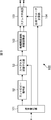
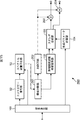
- FIG. 9 is a block diagram showing a configuration example of the first embodiment of the speech processing apparatus to which the present invention is applied.
- the 9 mainly includes a demultiplexing unit 101 in place of the demultiplexing unit 41 and the demultiplexing unit 51, and the IMDCT unit 54 and the reverberation signal generating unit 71.
- the point that the uncorrelated frequency time conversion unit 102 is provided instead, and the point that the stereo synthesis unit 103 and the generation parameter calculation unit 104 are provided instead of the stereo synthesis unit 72 and the generation parameter calculation unit 43, 4 is different from the configuration of the decoding device 40 of FIG. 4 including the audio signal decoding unit 42 of FIG. 5 and the stereo signal generation unit 44 of FIG.
- the audio processing device 100 decodes, for example, encoded data that has been spatially encoded by the encoding device 10 of FIG. 1 including the audio signal encoding unit 13 of FIG. At this time, the sound processing apparatus 100 generates a signal X D ′ that is irrelevant to the monaural signal X M used when generating the stereo signal, using the frequency spectrum coefficient of the monaural signal X M.
- the demultiplexing unit 101 acquisition means of the speech processing apparatus 100 corresponds to the demultiplexing unit 41 in FIG. 4 and the demultiplexing unit 51 in FIG. That is, the demultiplexing unit 101 performs demultiplexing on the multiplexed encoded data supplied from the encoding device 10 of FIG. 1, and acquires encoded data and BC parameters.
- the BC parameter multiplexed into the encoded data may be a BC parameter for all frames or a BC parameter for a predetermined frame, but here, for a predetermined frame, It is assumed that it is a BC parameter.
- the demultiplexing unit 101 performs demultiplexing on the encoded data, obtains frequency spectrum coefficients and quantization information that are quantized and entropy-coded. Then, the demultiplexing unit 101 supplies the quantized and entropy-encoded frequency spectrum coefficients to the entropy decoding unit 52, and supplies the quantization information to the spectrum dequantization unit 53. Also, the demultiplexing unit 101 supplies the BC parameter to the generation parameter calculation unit 104.
- the uncorrelated frequency time conversion unit 102 obtains a monaural signal X M and a signal that are two uncorrelated two time domain signals from the frequency spectrum coefficient of the monaural signal X M obtained as a result of the inverse quantization by the spectrum inverse quantization unit 53. X D ′ is generated. Then, the uncorrelated frequency time conversion unit 102 supplies the monaural signal X M and the signal X D ′ to the stereo synthesis unit 103. Details of the uncorrelated frequency time conversion unit 102 will be described with reference to FIGS.
- the stereo synthesizing unit 103 (synthesizing unit) synthesizes the monaural signal X M and the signal X D ′ supplied from the uncorrelated frequency time conversion unit 102 using the generation parameter supplied from the generation parameter calculation unit 104. Then, the stereo synthesis unit 103 outputs the audio signal X L and the audio signal X R for the right for a left obtained as a result of synthesis as a stereo signal. Details of the stereo synthesizing unit 103 will be described with reference to FIG.
- the generation parameter calculation unit 104 interpolates the BC parameter for the predetermined frame supplied from the demultiplexing unit 101, and calculates the BC parameter of each frame.
- the generation parameter calculation unit 104 generates a generation parameter using the BC parameter of the current processing target frame, and supplies the generation parameter to the stereo synthesis unit 103.
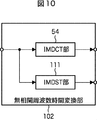
- FIG. 10 is a block diagram illustrating a detailed configuration example of the uncorrelated frequency time conversion unit 102 of FIG.
- IMDCT unit 54 is composed of an IMDCT unit 54 and an IMDST unit 111.
- the IMDCT unit 54 (first conversion means) in FIG. 10 is the same as the IMDCT unit 54 in FIG. 5 and uses the IMDCT for the frequency spectrum coefficient of the monaural signal X M supplied from the spectrum inverse quantization unit 53. I do. Then, the IMDCT unit 54 supplies the monaural signal X M (first time domain signal), which is a time domain signal obtained as a result, to the stereo synthesis unit 103 (FIG. 9).
- An IMDST (Inverse Modified Discrete Sine Transform) unit 111 (second conversion unit) performs IMDST on the frequency spectrum coefficient of the monaural signal X M supplied from the spectrum inverse quantization unit 53. Then, the IMDST unit 111 supplies a signal X D ′ (second time domain signal), which is a time domain signal obtained as a result, to the stereo synthesis unit 103 (FIG. 9).
- X D ′ second time domain signal
- the transformation by the IMDCT unit 54 is an inverse transformation of cosine
- the transformation by the IMDST unit 111 is an inverse transformation of sine
- the basis in the transformation by the IMDCT unit 54 and the basis in the transformation by the IMDST unit 111 are orthogonal to each other. Yes. Therefore, the monaural signal X M and the signal X D ′ can be regarded as substantially uncorrelated signals.
- MDCT, IMDCT, and IMDST are defined by the following equations (1) to (3), respectively.
- x (n) is a time domain signal
- w (n) is a transformation window
- w ′ (n) is an inverse transformation window
- y (n) is an inverse transformation. It is a later signal.
- Xc (k) is an MDCT coefficient
- Xs (k) is an MDST coefficient.
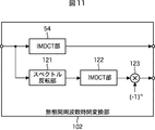
- FIG. 11 is a block diagram illustrating another detailed configuration example of the uncorrelated frequency time conversion unit 102 of FIG.
- uncorrelated frequency time conversion section 102 in FIG. 11 is mainly different from the configuration in FIG. 10 in that spectrum inversion section 121, IMDCT section 122, and code inversion section 123 are provided instead of IMDST section 111. .
- the spectrum inversion unit 121 of the non-correlated frequency time conversion unit 102 in FIG. 11 inverts the frequency spectrum coefficient supplied from the spectrum inverse quantization unit 53 so that the frequencies are in reverse order, and supplies the inverted frequency spectrum coefficient to the IMDCT unit 122.
- the IMDCT unit 122 performs IMDCT on the frequency spectrum coefficient supplied from the spectrum inversion unit 121 to obtain a time domain signal.
- the IMDCT unit 122 supplies the time domain signal to the sign inverting unit 123.
- the sign inversion unit 123 inverts the sign of the odd-numbered sample of the time domain signal supplied from the IMDCT unit 122 to obtain a signal X D ′.
- equation (3) when Xs (k) is replaced with Xs (Nk-1), if N is a general multiple of 4, equation (3) can be expressed as It can deform
- the signal obtained as a result of performing IMDST on the frequency spectrum coefficient from the spectrum inverse quantization unit 53 and the frequency spectrum coefficient are inverted so that the frequencies are in reverse order, the IMDST is performed, and the code of the odd sample is obtained.
- the signals obtained as a result of the inversion become the same signal X D ′. That is, the IMDST unit 111 in FIG. 10 is equivalent to the spectrum inversion unit 121, the IMDCT unit 122, and the sign inversion unit 123 in FIG.
- the sign inversion unit 123 supplies the obtained signal X D ′ to the stereo synthesis unit 103 in FIG.
- the uncorrelated frequency time conversion unit 102 in FIG. 11 only needs to provide the IMDCT unit in order to convert the time domain signal into the frequency spectrum coefficient, and therefore it is necessary to provide the IMDCT unit and the IMDST unit in FIG. Compared with the case where there is, manufacturing cost can be reduced.
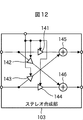
- FIG. 12 is a block diagram illustrating a detailed configuration example of the stereo synthesis unit 103 in FIG. 9.
- 12 includes multipliers 141 to 144, an adder 145, and an adder 146.
- the multiplier 141 multiplies the monaural signal X M supplied from the uncorrelated frequency time conversion unit 102 by a coefficient h 11 that is one of the generation parameters supplied from the generation parameter calculation unit 104.
- the multiplier 141 supplies the resultant multiplication value h 11 ⁇ X M to the adder 145.
- the multiplier 142 multiplies the monaural signal X M supplied from the uncorrelated frequency time conversion unit 102 by a coefficient h 21 that is one of the generation parameters supplied from the generation parameter calculation unit 104.
- the multiplier 141 supplies the resultant multiplication value h 21 ⁇ X M to the adder 146.
- the multiplier 143 multiplies the signal X D ′ supplied from the uncorrelated frequency time conversion unit 102 by a coefficient h 12 that is one of the generation parameters supplied from the generation parameter calculation unit 104.
- the multiplier 141 supplies the resultant multiplication value h 12 ⁇ X D ′ to the adder 145.
- the multiplier 144 multiplies the signal X D ′ supplied from the uncorrelated frequency time conversion unit 102 by a coefficient h 22 that is one of the generation parameters supplied from the generation parameter calculation unit 104.
- the multiplier 141 supplies the resultant multiplication value h 22 ⁇ X D ′ to the adder 146.
- the adder 145 adds the multiplication value h 11 ⁇ X M supplied from the multiplier 141 and the multiplication value h 12 ⁇ X D ′ supplied from the multiplier 143, and uses the resulting addition value as the left audio. and outputs it as the signal X L.
- the adder 146 adds the multiplication value h 21 ⁇ X M supplied from the multiplier 142 and the multiplication value h 22 ⁇ X D ′ supplied from the multiplier 143, and uses the resulting addition value for the right side. outputs as the audio signal X R.
- the stereo synthesizing unit 103 As described above, in the stereo synthesizing unit 103, as shown in FIG. 13, the following equations are used with the monaural signal X M , the signal X D ′, the left audio signal X L , and the right audio signal X R as vectors. As shown in (5), weighted addition using a generation parameter is performed.
- the coefficients h 11 , h 12 , h 21 , and h 22 are expressed by the following formula (6).
- the angle ⁇ L is an angle formed by the vector of the left audio signal X L and the vector of the monaural signal X M
- the angle ⁇ R is the vector of the right audio signal X R and the monaural signal X.
- the coefficients h 11 , h 12 , h 21 , and h 22 are calculated as generation parameters by the generation parameter calculation unit 104.
- the generation parameter calculation unit 104 calculates g L , g R , ⁇ L , and ⁇ R from the BC parameter, and calculates coefficients h 11 , h from the g L , g R , ⁇ L , and ⁇ R. 12 , h 21 , and h 22 are calculated as generation parameters. Details of a method for calculating g L , g R , ⁇ L , and ⁇ R from the BC parameters are described in, for example, Japanese Patent Application Laid-Open No. 2006-325162.
- g L , g R , ⁇ L , and ⁇ R can be used as the BC parameter, and those obtained by compression-coding g L , g R , ⁇ L , and ⁇ R can also be used. Also, as the BC parameter, the coefficients h 11 , h 12 , h 21 , and h 22 can be used directly or after being compression-coded.
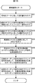
- FIG. 14 is a flowchart for explaining the decoding process by the speech processing apparatus 100 of FIG. This decoding process is started when multiplexed encoded data supplied from the encoding apparatus 10 in FIG. 1 is input to the audio processing apparatus 100.
- step S11 of FIG. 14 the demultiplexing unit 101 performs demultiplexing on the multiplexed encoded data supplied from the encoding apparatus 10 of FIG. 1, and acquires encoded data and BC parameters. . Further, the demultiplexer 101 further demultiplexes the encoded data, obtains frequency spectrum coefficients and quantization information that have been quantized and entropy encoded. Then, the demultiplexing unit 101 supplies the quantized and entropy-encoded frequency spectrum coefficients to the entropy decoding unit 52, and supplies the quantization information to the spectrum dequantization unit 53. Also, the demultiplexing unit 101 supplies the BC parameter to the generation parameter calculation unit 104.
- step S12 the entropy decoding unit 52 performs entropy decoding such as Huffman decoding and arithmetic decoding on the frequency spectrum coefficient supplied from the demultiplexing unit 101, and restores the quantized frequency spectrum coefficient.
- the entropy decoding unit 52 supplies the frequency spectrum coefficient to the spectrum inverse quantization unit 53.
- step S ⁇ b> 13 the spectrum inverse quantization unit 53 performs inverse quantization on the quantized frequency spectrum coefficient supplied from the entropy decoding unit 52 based on the quantization information supplied from the demultiplexing unit 101. To restore the frequency spectral coefficients. Then, the spectrum inverse quantization unit 53 supplies the frequency spectrum coefficient to the uncorrelated frequency time conversion unit 102.
- step S14 uncorrelated frequency-time conversion unit 102, the frequency spectral coefficients of the mono signal X M obtained as a result of the inverse quantization by the spectrum inverse quantization unit 53, the monaural signal is two time domain signals uncorrelated to each other X M and signal X D ′ are generated. Then, the uncorrelated frequency time conversion unit 102 supplies the monaural signal X M and the signal X D ′ to the stereo synthesis unit 103.
- step S ⁇ b> 15 the stereo synthesizing unit 103 synthesizes the monaural signal X M and the signal X D ′ supplied from the uncorrelated frequency time conversion unit 102 using the generation parameter supplied from the generation parameter calculation unit 104.
- step S16 the generation parameter calculation unit 104 interpolates the BC parameter for the predetermined frame supplied from the demultiplexing unit 101, and calculates the BC parameter for each frame.
- step S ⁇ b> 17 the generation parameter calculation unit 104 generates coefficients h 11 , h 12 , h 21 , and h 22 as generation parameters using the BC parameter of the current processing target frame, and supplies the generated parameters to the stereo synthesis unit 103. .
- step S ⁇ b> 18 the stereo synthesis unit 103 synthesizes the monaural signal X M and the signal X D ′ supplied from the uncorrelated frequency time conversion unit 102 using the generation parameter supplied from the generation parameter calculation unit 104, and stereo. Generate a signal. Then, the stereo synthesizing unit 103 outputs a stereo signal, and the process ends.
- the audio processing apparatus 100 generates a monaural signal X M and the signal X D 'by carrying out the two transformations base is orthogonal to the frequency spectral coefficient of the mono signal X M. That is, the audio processing apparatus 100 can generate the signal X D ′ using the frequency spectrum coefficient of the monaural signal X M. Therefore, in the audio processing apparatus 100, the delay by the reverberation signal generation unit 71 in FIG. 7 is compared with the decoding apparatus 40 in FIG. 4 that includes the audio signal decoding unit 42 in FIG. 5 and the stereo signal generation unit 44 in FIG. An increase in resources such as a calculation amount and a buffer can be suppressed.
- the IMDCT unit 54 of the conventional decoding device 40 can be reused as a part of the uncorrelated frequency time conversion unit 102, the addition of new functions can be minimized, and the circuit scale and necessary resources can be increased. Can be suppressed.
- FIG. 15 is a block diagram showing a configuration example of the second embodiment of the speech processing apparatus to which the present invention is applied.
- FIG. 15 is different from the configuration of FIG. 9 mainly in that a band dividing unit 201, an IMDCT unit 202, an adder 203, and an adder 204 are newly provided.
- the audio processing device 200 performs, for example, the same spatial encoding as that of the encoding device 10 of FIG. 1 including the audio signal encoding unit 13 of FIG. 2, and is encoded data in which BC parameters for high frequencies are multiplexed. decodes and stereo only monaural signal X M of the high frequency range.
- the band dividing unit 201 (dividing unit) of the speech processing device 200 calculates the frequency spectrum coefficient obtained by the spectrum inverse quantization unit 53 by using a frequency spectrum coefficient of a high frequency and a frequency spectrum coefficient of a low frequency depending on the frequency. Divide into two groups. Then, the band division unit 201 supplies the low frequency spectrum coefficient to the IMDCT unit 202 and supplies the high frequency spectrum coefficient to the uncorrelated frequency time conversion unit 102.
- the IMDCT unit 202 (third conversion unit) performs IMDCT on the low frequency spectrum coefficient supplied from the band dividing unit 201, and outputs a monaural signal X M low (third signal) that is a low frequency domain signal. Time domain signal).
- the IMDCT unit 202 supplies the low-frequency monaural signal X M low to the adder 203 as a low-frequency left audio signal and also supplies the low-frequency monaural signal X M low to the adder 204 as a low-frequency right audio signal.
- the adder 203 the high frequency left spectrum obtained as a result of the processing performed by the uncorrelated frequency time conversion unit 102 and the stereo synthesis unit 103 on the high frequency spectrum coefficient output from the band dividing unit 201 is used.
- An audio signal X L High is input.
- the adder 203 adds the high-frequency left audio signal X L High and the low-frequency monaural signal X M low supplied from the IMDCT unit 202 as the low-frequency left audio signal, Left audio signal XL is generated.
- the adder 204 uses the high-frequency frequency spectrum coefficient output from the band dividing unit 201 for the high-frequency right obtained as a result of processing performed by the uncorrelated frequency time conversion unit 102 and the stereo synthesis unit 103. Audio signal X R High is input. The adder 204 adds the high-frequency right audio signal X R High and the low-frequency monaural signal X M low supplied from the IMDCT unit 202 as the low-frequency right audio signal, and it outputs the audio signal X R for the right frequency band.
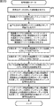
- FIG. 16 is a flowchart for explaining decoding processing by the speech processing apparatus 200 of FIG.
- spatial encoding similar to that of the encoding device 10 of FIG. 1 provided with the audio signal encoding unit 13 of FIG. 2 is performed, and encoded data in which BC parameters for high frequencies are multiplexed is speech It starts when it is input to the processing device 200.
- steps S31 to S33 in FIG. 16 are the same as the processing in steps S11 to S13 in FIG.
- step S34 the band dividing unit 201 divides the frequency spectrum coefficient obtained by the spectrum inverse quantization unit 53 into two groups of a high frequency spectrum coefficient and a low frequency spectrum coefficient according to the frequency. Then, the band division unit 201 supplies the low frequency spectrum coefficient to the IMDCT unit 202 and supplies the high frequency spectrum coefficient to the uncorrelated frequency time conversion unit 102.
- step S35 the IMDCT unit 202 performs IMDCT on the low frequency spectrum coefficient supplied from the band dividing unit 201 to obtain a monaural signal X M low that is a low frequency domain signal.
- the IMDCT unit 202 supplies the low-frequency monaural signal X M low to the adder 203 as a low-frequency left audio signal and also supplies the low-frequency monaural signal X M low to the adder 204 as a low-frequency right audio signal.
- step S ⁇ b> 36 the uncorrelated frequency time conversion unit 102, the stereo synthesis unit 103, and the generation parameter calculation unit 104 perform stereo signal generation processing on the high frequency spectrum coefficients supplied from the band division unit 201. Specifically, the uncorrelated frequency time conversion unit 102, the stereo synthesis unit 103, and the generation parameter calculation unit 104 perform the processes of steps S14 to S18 in FIG.
- the resulting high frequency left audio signal X L High is input to the adder 203, and the high frequency right audio signal X R High is input to the adder 204.
- step S37 the adder 203 outputs the low-frequency monaural signal X M low supplied as the low-frequency left audio signal from the IMDCT unit 202 and the high-frequency left-use signal supplied from the uncorrelated frequency time conversion unit 102.
- the audio signal X L High is added to generate the left audio signal X L in the entire frequency band.
- the adder 203 outputs the audio signal X L for the left of the entire frequency band.
- step S ⁇ b> 38 the adder 204 performs a low-frequency monaural signal X M low supplied as a low-frequency right audio signal from the IMDCT unit 202 and a high-frequency right signal supplied from the uncorrelated frequency time conversion unit 102.
- the audio signal X R High for use is added to generate the right audio signal X R for the entire frequency band.
- the adder 204 outputs the audio signal X R for the right of the entire frequency band.
- the audio processing unit 200 decodes the encoded data of monaural signal X M of the entire frequency band, to stereo only high band.
- the stereo mono signal X M of the low frequency the sound can be prevented from becoming unnatural.
- the band dividing unit 201 divides the frequency spectrum coefficient into the high frequency spectrum coefficient and the low frequency spectrum coefficient, but the frequency spectrum coefficient in a predetermined frequency band and the frequency spectrum in other frequency bands. You may make it divide
- FIG. 17 is a block diagram illustrating a configuration example of the third embodiment of the speech processing device to which the present invention has been applied.
- the 17 mainly includes a demultiplexing unit 301 in place of the demultiplexing unit 41 and the demultiplexing unit 61, the IMDCT unit 64-1 to the IMDCT unit 64- IMDCT sections 304-1 to 304- (N-1) are provided instead of (N-1), and a stereo section 305 is provided instead of the IMDCT section 64-N and the stereo signal generation section 44.
- the generation parameter calculation unit 104 and the synthesis filter bank 306 are provided instead of the generation parameter calculation unit 43 and the synthesis filter bank 65.
- the audio signal decoding unit 42 in FIG. 6 and the stereo signal generation unit in FIG. 4 is different from the configuration of the decoding device 40 of FIG.
- the audio processing device 300 in FIG. 17 performs, for example, the same spatial coding as the coding device 10 in FIG. 1 including the audio signal coding unit 13 in FIG. 3, and multiplexes BC parameters of predetermined subband signals.
- the encoded data is decoded.
- the demultiplexing unit 301 of the speech processing device 300 corresponds to the demultiplexing unit 41 in FIG. 4 and the demultiplexing unit 61 in FIG. That is, the demultiplexing unit 301 performs spatial coding similar to that of the coding apparatus 10 of FIG. 1 including the audio signal coding unit 13 of FIG. 3, and multiplexes BC parameters of predetermined subband signals. Encoded data is input. The demultiplexing unit 301 performs demultiplexing on the input encoded data, and obtains BC parameters of the encoded data and a predetermined subband signal. Then, the demultiplexing unit 301 supplies the BC parameter of the predetermined subband signal to the generation parameter calculation unit 104.
- the demultiplexer 301 demultiplexes the encoded data, obtains the frequency spectrum coefficients and quantization information of the N subband signals that are quantized and entropy-coded.
- the demultiplexing unit 301 supplies the frequency spectrum coefficients of the N subband signals that are quantized and entropy-coded to the entropy decoding unit 62 and supplies the quantization information to the spectrum dequantization unit 63.
- the frequency spectral coefficients of the N subband signals restored by the spectrum inverse quantization unit 63 are Input one by one.
- the IMDCT units 304-1 to 304- (N-1) respectively supply the subband signal X M i to the synthesis filter bank 306 as the left audio signal X L i and the right audio signal X R i .
- the stereo unit 305 includes the uncorrelated frequency time conversion unit 102 and the stereo synthesis unit 103 shown in FIG.
- Stereo processing section 305 uses the generation parameter generated by generation parameter calculation section 104 and uses the frequency spectrum coefficient of a predetermined subband signal input from spectrum inverse quantization section 63 to perform left audio that is a time domain signal.
- a signal subband signal X L A and a right audio signal subband signal X R A are generated.
- the stereo processing unit 305 supplies the left subband signal X L A and the right subband signal X R A to the synthesis filter bank 306.
- the synthesis filter bank 306 (adding means) includes a left synthesis filter bank for synthesizing a subband signal of the left audio signal and a right synthesis filter bank for synthesizing a subband signal of the right audio signal. Is done.
- the left synthesis filter bank of the synthesis filter bank 306 includes the left subband signals X L 1 to X L N ⁇ 1 from the IMDCT units 304-1 to 304- (N ⁇ 1) and the left sub-band signals from the stereo unit 305.
- the subband signal X L A is synthesized. Then, for left synthesis filterbank outputs the audio signal X L for the left of all the frequency band obtained as a result of synthesis.
- the right synthesis filter bank of the synthesis filter bank 306 includes right subband signals X R 1 to X R N ⁇ 1 from the IMDCT units 304-1 to 304- (N ⁇ 1), and a stereo unit 305. From the right sub-band signal X R A is synthesized. Then, the right for the synthesis filter bank outputs an audio signal X R for the right of the entire frequency band obtained as a result of synthesis.
- stereoization is performed for only one subband signal, but stereoization may be performed for a plurality of subband signals.
- the subband signal to be stereo-ized may be dynamically set on the encoding side instead of being set in advance. In this case, for example, information for specifying a subband signal to be stereoized is included in the BC parameter.
- FIG. 18 is a flowchart for explaining decoding processing by the audio processing device 300 of FIG.
- this decoding process for example, spatial encoding similar to that of the encoding device 10 of FIG. 1 including the audio signal encoding unit 13 of FIG. 3 is performed, and BC parameters of a predetermined subband signal are multiplexed. Triggered when data is input to the audio processing device 300.
- step S51 of FIG. 18 the demultiplexing unit 301 performs demultiplexing on the input encoded data, and obtains BC parameters of the encoded data and a predetermined subband signal. Then, the demultiplexing unit 301 supplies the BC parameter of the predetermined subband signal to the generation parameter calculation unit 104. Also, the demultiplexing unit 301 performs demultiplexing on the encoded data, obtains frequency spectrum coefficients and quantization information of the N subband signals that are quantized and entropy encoded. The demultiplexing unit 301 supplies the frequency spectrum coefficients of the N subband signals that are quantized and entropy-coded to the entropy decoding unit 62 and supplies the quantization information to the spectrum dequantization unit 63.
- step S52 the entropy decoding unit 62 performs entropy decoding on the frequency spectrum coefficients of the N subband signals supplied from the demultiplexing unit 101, and supplies the result to the spectrum inverse quantization unit 63.
- step S ⁇ b> 53 the spectrum dequantization unit 63 performs the N subband signals obtained as a result of entropy decoding supplied from the entropy decoding unit 62 based on the quantization information supplied from the demultiplexing unit 301. Inverse quantization is performed for each frequency spectrum coefficient. Then, the spectrum inverse quantization unit 63 supplies the frequency spectrum coefficients of the N subband signals restored as a result to the IMDCT units 304-1 to 304- (N-1) and the stereoization unit 305 one by one. To do.
- step S ⁇ b> 55 the stereolation unit 305 uses the generation parameter supplied from the generation parameter calculation unit 104 to generate a stereo signal for the frequency spectrum coefficient of the predetermined subband signal supplied from the spectrum inverse quantization unit 63. Perform the generation process. Then, the stereo processing section 305 supplies the subband signal X L A of the left audio signal and the subband signal X R A of the right audio signal, which are time domain signals obtained as a result, to the synthesis filter bank 306.
- step S56 the left synthesis filter bank of the synthesis filter bank 306 synthesizes all subband signals of the left audio signal supplied from the IMDCT units 304-1 to 304- (N-1) and the stereo unit 305, respectively. Te, and generates an audio signal X L for the left of the entire frequency band. Then, for left synthesis filter bank outputs an audio signal X L for the left of the entire frequency band.
- step S57 the right synthesis filter bank of the synthesis filter bank 306 outputs all subband signals of the right audio signal supplied from the IMDCT units 304-1 to 304- (N-1) and the stereo unit 305, respectively. synthesized and generates an audio signal X R for the right of all the frequency bands. Then, the right for the synthesis filter bank outputs an audio signal X R for the right of the entire frequency band.
- FIG. 19 is a block diagram illustrating a configuration example of the fourth embodiment of the speech processing device to which the present invention has been applied.
- 19 mainly includes a spectrum separation unit 401 instead of the band division unit 201, IMDCTs 402 and 403 instead of the IMDCT unit 202, and includes an adder 203 and an adder 204. Instead, an adder 404 and an adder 405 are provided, which is different from the configuration of FIG.
- the speech processing device 400 is intensity-encoded encoded data in which BC parameters of frequencies equal to or higher than the intensity start frequency Fis are multiplexed instead of a conventional level ratio of frequency spectrum coefficients between channels. Decrypt data.
- the encoded data is decoded by the audio processor 400, for example, a stereo signal to be encoded down-mixed to mono signal X M, Inten of the resulting mono signal X M and the stereo signal to be encoded
- a frequency component equal to or higher than the city start frequency Fis is extracted by a high-pass filter or the like, and is generated by an encoding device that detects BC parameters.
- the spectrum separation unit 401 (separation unit) of the speech processing device 400 obtains the frequency spectrum coefficient restored by the spectrum inverse quantization unit 53.
- the spectrum separation unit 401 separates the frequency spectrum coefficient into a frequency spectrum coefficient of a stereo signal having a frequency lower than the intensity start frequency Fis and a frequency spectrum coefficient of a monaural signal X M high having a frequency equal to or higher than the intensity start frequency Fis. .
- the spectrum separation unit 401 supplies the frequency spectrum coefficient of the left audio signal X L low of the stereo signal having a frequency lower than the intensity start frequency Fis to the IMDCT unit 402, and the frequency spectrum coefficient of the right audio signal X R low is obtained. This is supplied to the IMDCT unit 403.
- the spectrum separation unit 401 supplies the frequency spectrum coefficient of the monaural signal X M high to the uncorrelated frequency time conversion unit 102.
- the IMDCT unit 402 (third conversion unit) performs IMDCT on the frequency spectrum coefficient of the left audio signal X L low supplied from the spectrum separation unit 401, and uses the resulting left audio signal X L low as a result. This is supplied to the adder 404.
- the IMDCT unit 403 (third conversion unit) performs IMDCT on the frequency spectrum coefficient of the right audio signal X R low supplied from the spectrum separation unit 401 and obtains the right audio signal X R obtained as a result. low is supplied to the adder 405.
- the adder 404 (adding means) includes a left audio signal X L high that is a time domain signal having a frequency equal to or higher than the intensity start frequency Fis generated by the stereo synthesis unit 103, and a left audio signal supplied from the IMDCT unit 402. The signal X L low is added. The adder 404 outputs an audio signal obtained as a result as the audio signal X L for the left of the entire frequency band.
- the adder 405 (adding means) is a right audio signal X R high that is a time domain signal having a frequency equal to or higher than the intensity start frequency Fis generated by the stereo synthesizer 103, and the right supplied from the IMDCT unit 402. Audio signal X R low is added.
- the adder 405 outputs an audio signal obtained as a result as the audio signal X R for the right of all the frequency bands.
- the speech processing apparatus 400 uses the BC parameter multiplexed with the intensity-encoded encoded data, and uses the BC parameter multiplexed with the intensity encoding to generate a frequency component equal to or higher than the intensity start frequency Fis. To stereo. This makes it possible to restore the stereo effect of the frequency component equal to or higher than the intensity start frequency Fis, as compared to the conventional intensity decoding apparatus that performs stereo using the frequency spectrum coefficient level ratio between channels.
- FIG. 20 is a flowchart for explaining decoding processing by the audio processing device 400 of FIG. This decoding process is started when, for example, encoded data in which intensity coding is performed and BC parameters having a frequency equal to or higher than the intensity start frequency Fis are multiplexed is input.
- the spectrum separation unit 401 uses the frequency spectrum coefficient restored by the spectrum inverse quantization unit 53 as a frequency spectrum coefficient of a stereo signal having a frequency lower than the intensity start frequency Fis and a frequency equal to or higher than the intensity start frequency Fis. Are separated into frequency spectrum coefficients of the monaural signal X M high .
- the spectrum separation unit 401 supplies the frequency spectrum coefficient of the left audio signal X L low of the stereo signal having a frequency lower than the intensity start frequency Fis to the IMDCT unit 402, and the frequency spectrum coefficient of the right audio signal X R low is obtained. This is supplied to the IMDCT unit 403.
- the spectrum separation unit 401 supplies the frequency spectrum coefficient of the monaural signal X M high to the uncorrelated frequency time conversion unit 102.
- step S75 the IMDCT unit 402 performs IMDCT on the frequency spectrum coefficient of the left audio signal X L low supplied from the spectrum separation unit 401. Then, the IMDCT unit 402 supplies the left audio signal X L low obtained as a result to the adder 404.
- step S76 the IMDCT unit 403 performs IMDCT on the frequency spectrum coefficient of the right audio signal X R low supplied from the spectrum separation unit 401. Then, the IMDCT unit 403 supplies the right audio signal X R low obtained as a result to the adder 405.
- step S77 the uncorrelated frequency time conversion unit 102, the stereo synthesis unit 103, and the generation parameter calculation unit 104 perform stereo signal generation processing on the frequency spectrum coefficient of the monaural signal X M high from the spectrum separation unit 401.
- the left audio signal X L high which is the time domain signal obtained as a result, is supplied to the adder 404, and the right audio signal X R high is supplied to the adder 405.
- step S78 the adder 404 adds the left audio signal X L low having a frequency lower than the intensity start frequency Fis from the IMDCT unit 402 and the left audio signal having a frequency equal to or higher than the intensity start frequency Fis from the stereo synthesis unit 103.
- X L high is added to generate a left audio signal X L in the entire frequency band.
- the adder 404 outputs the audio signal X L for the left.
- step S79 the adder 405 outputs the right audio signal X R low having a frequency lower than the intensity start frequency Fis from the IMDCT unit 403 and the right audio signal having a frequency equal to or higher than the intensity start frequency Fis from the stereo synthesis unit 103. by adding the audio signal X R high, and generates an audio signal X R for the right of all the frequency bands. The adder 405 outputs the audio signal X R for the right.
- speech processing apparatus 100 decodes encoded data that has been time-frequency converted by MDCT
- IMDCT has been performed during frequency-time conversion.
- frequency-time conversion is performed.
- the uncorrelated time-frequency transform unit 102 uses the IMDCT transform and the IMDST transform as transforms whose bases are orthogonal to each other, but other overlapping orthogonal transforms such as a sine transform and a cosine transform are used. Also good.
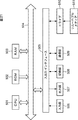
- FIG. 21 shows a configuration example of an embodiment of a computer in which a program for executing the above-described series of processing is installed.
- the program can be recorded in advance in a storage unit 508 or a ROM (Read Only Memory) 502 as a recording medium built in the computer.
- the program can be stored (recorded) in the removable medium 511.
- a removable medium 511 can be provided as so-called package software.
- examples of the removable medium 511 include a flexible disk, a CD-ROM (Compact Disc Read Only Memory), an MO (Magneto Optical) disc, a DVD (Digital Versatile Disc), a magnetic disc, and a semiconductor memory.
- the program can be installed on the computer from the removable medium 511 as described above via the drive 510, or can be downloaded to the computer via a communication network or a broadcast network and installed in the built-in storage unit 508. That is, the program is transferred from a download site to a computer wirelessly via a digital satellite broadcasting artificial satellite, or wired to a computer via a network such as a LAN (Local Area Network) or the Internet. be able to.
- LAN Local Area Network
- the computer includes a CPU (Central Processing Unit) 501, and an input / output interface 505 is connected to the CPU 501 via a bus 504.
- CPU Central Processing Unit
- input / output interface 505 is connected to the CPU 501 via a bus 504.
- the CPU 501 executes a program stored in the ROM 502 according to an instruction input by the user operating the input unit 506 via the input / output interface 505. Alternatively, the CPU 501 loads a program stored in the storage unit 508 into a RAM (Random Access Memory) 503 and executes it.
- a RAM Random Access Memory
- the CPU 501 performs processing according to the flowchart described above or processing performed by the configuration of the block diagram described above. Then, the CPU 501 outputs the processing result as necessary, for example, via the input / output interface 505, from the output unit 507, transmitted from the communication unit 509, and further recorded in the storage unit 508.
- the input unit 506 includes a keyboard, a mouse, a microphone, and the like.
- the output unit 507 includes an LCD (Liquid Crystal Display), a speaker, and the like.
- the processing performed by the computer according to the program does not necessarily have to be performed in chronological order in the order described as the flowchart. That is, the processing performed by the computer according to the program includes processing executed in parallel or individually (for example, parallel processing or object processing).
- the program may be processed by one computer (processor), or may be distributedly processed by a plurality of computers. Furthermore, the program may be transferred to a remote computer and executed.
- the present invention can be applied to a pseudo stereo technique for audio signals.
- IMDCT unit 100 speech processing unit, 101 demultiplexing unit, 103 stereo synthesis unit, 111 IMDST unit, 121 spectrum inversion unit, 122 IMDCT unit, 123 code inversion unit, 200 speech processing unit, 201 band division unit, 202 IMDCT Unit, 203, 204 adder, 300 speech processing unit, 301 demultiplexing unit, 304-1 to 304-N IMDCT unit, 305 stereolation unit, 306 synthesis filter bank, 400 speech processing unit, 401 spectrum separation unit, 402 403 IMDCT part 404, 405 adder
Landscapes
- Engineering & Computer Science (AREA)
- Physics & Mathematics (AREA)
- Audiology, Speech & Language Pathology (AREA)
- Computational Linguistics (AREA)
- Signal Processing (AREA)
- Health & Medical Sciences (AREA)
- Human Computer Interaction (AREA)
- Acoustics & Sound (AREA)
- Multimedia (AREA)
- Spectroscopy & Molecular Physics (AREA)
- Mathematical Physics (AREA)
- Stereophonic System (AREA)
- Compression, Expansion, Code Conversion, And Decoders (AREA)
Abstract
Description
[音声処理装置の第1実施の形態の構成例]
図9は、本発明を適用した音声処理装置の第1実施の形態の構成例を示すブロック図である。
図10は、図9の無相関周波数時間変換部102の詳細構成例を示すブロック図である。



図11は、図9の無相関周波数時間変換部102の他の詳細構成例を示すブロック図である。
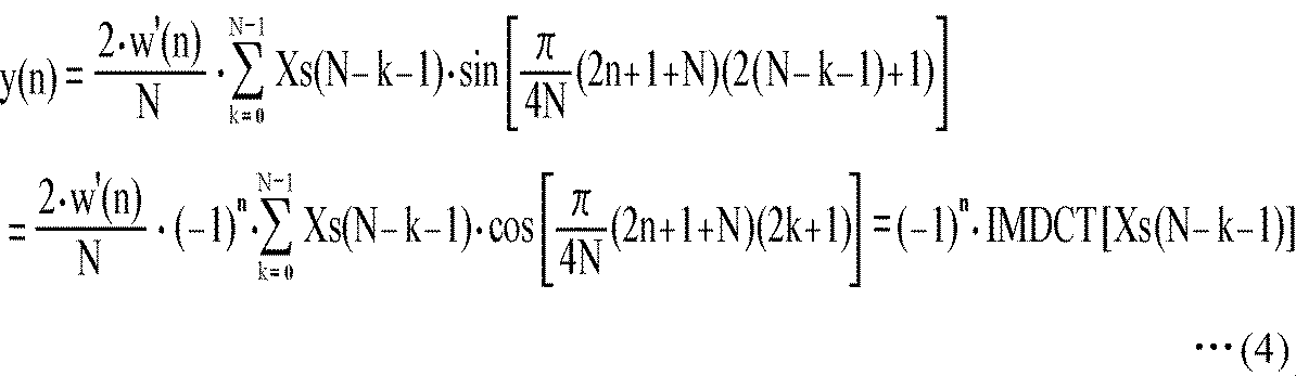
図12は、図9のステレオ合成部103の詳細構成例を示すブロック図である。


図14は、図9の音声処理装置100による復号処理を説明するフローチャートである。この復号処理は、図1の符号化装置10から供給される多重化された符号化データが音声処理装置100に入力されたとき、開始される。
[音声処理装置の第2実施の形態の構成例]
図15は、本発明を適用した音声処理装置の第2実施の形態の構成例を示すブロック図である。
図16は、図15の音声処理装置200による復号処理を説明するフローチャートである。この復号処理は、図2のオーディオ信号符号化部13を備える図1の符号化装置10と同様の空間符号化が行われ、高域についてのBCパラメータが多重化された符号化データが、音声処理装置200に入力されたとき、開始される。
[音声処理装置の第3実施の形態の構成例]
図17は、本発明を適用した音声処理装置の第3実施の形態の構成例を示すブロック図である。
図18は、図17の音声処理装置300による復号処理を説明するフローチャートである。この復号処理は、例えば、図3のオーディオ信号符号化部13を備える図1の符号化装置10と同様の空間符号化が行われ、所定のサブバンド信号のBCパラメータが多重化された符号化データが音声処理装置300に入力されたとき、開始される。
[音声処理装置の第4実施の形態の構成例]
図19は、本発明を適用した音声処理装置の第4実施の形態の構成例を示すブロック図である。
図20は、図19の音声処理装置400による復号処理を説明するフローチャートである。この復号処理は、例えば、インテンシティ符号化され、インテンシティ開始周波数Fis以上の周波数のBCパラメータが多重化された符号化データが入力されたとき、開始される。
次に、上述した一連の処理は、ハードウェアにより行うこともできるし、ソフトウェアにより行うこともできる。一連の処理をソフトウェアによって行う場合には、そのソフトウェアを構成するプログラムが、汎用のコンピュータ等にインストールされる。
Claims (9)
- 複数チャンネルの音声の時間領域信号である音声信号から生成された前記複数チャンネルより少ないチャンネルの音声信号の周波数領域の係数と、前記複数チャンネルのチャンネル間の関係を表すパラメータとを取得する取得手段と、
前記取得手段により取得された前記周波数領域の係数を、第1の時間領域信号に変換する第1の変換手段と、
前記取得手段により取得された前記周波数領域の係数を、第2の時間領域信号に変換する第2の変換手段と、
前記パラメータを用いて前記第1の時間領域信号と前記第2の時間領域信号を合成することにより、前記複数チャンネルの音声信号を生成する合成手段と
を備え、
前記第1の変換手段による変換における基底と前記第2の変換手段による変換における基底は直交する
音声処理装置。 - 前記取得手段により取得された前記周波数領域の係数を、周波数によって複数のグループに分割する分割手段と、
前記複数のグループのうちの第1のグループに分割された前記周波数領域の係数を、第3の時間領域信号に変換する第3の変換手段と、
前記第3の時間領域信号を前記第1のグループの周波数帯域の各チャンネルの音声信号とし、その第3の時間領域信号と、前記合成手段により生成された前記複数チャンネルの音声信号とをチャンネルごとに加算して、全周波数帯域の前記複数チャンネルの音声信号を生成する加算手段と
をさらに備え、
前記取得手段は、前記周波数領域の係数と前記第1のグループ以外のグループである第2のグループの周波数帯域の前記パラメータを取得し、
前記第1の変換手段は、前記第2のグループに分割された前記周波数領域の係数を、前記第1の時間領域信号に変換し、
前記第2の変換手段は、前記第2のグループに分割された前記周波数領域の係数を、前記第2の時間領域信号に変換し、
前記合成手段は、前記パラメータを用いて前記第1の時間領域信号と前記第2の時間領域信号を合成することにより、前記第2のグループの周波数帯域の前記複数チャンネルの音声信号を生成する
請求項1に記載の音声処理装置。 - 前記取得手段により取得される周波数により複数のグループに分割された前記周波数領域の係数のうちの第1のグループの周波数領域の係数を、第3の時間領域信号に変換する第3の変換手段と、
前記第3の時間領域信号を前記第1のグループの周波数帯域の各チャンネルの音声信号とし、その第3の時間領域信号と、前記合成手段により生成された前記複数チャンネルの音声信号とをチャンネルごとに加算して、全周波数帯域の前記複数チャンネルの音声信号を生成する加算手段と
をさらに備え、
前記取得手段は、各グループの前記周波数領域の係数と、前記複数のグループのうちの前記第1のグループ以外のグループである第2のグループの周波数帯域の前記パラメータを取得し、
前記第1の変換手段は、前記第2のグループに分割された前記周波数領域の係数を、前記第1の時間領域信号に変換し、
前記第2の変換手段は、前記第2のグループに分割された前記周波数領域の係数を、前記第2の時間領域信号に変換し、
前記合成手段は、前記パラメータを用いて前記第1の時間領域信号と前記第2の時間領域信号を合成することにより、前記第2のグループの周波数帯域の前記複数チャンネルの音声信号を生成する
請求項1に記載の音声処理装置。 - 前記周波数領域の係数は、前記複数チャンネルの音声信号の周波数領域の係数から生成される
請求項1に記載の音声処理装置。 - 前記取得手段により取得された所定の周波数帯域の前記周波数領域の係数と、その周波数帯域以外の周波数帯域の前記複数チャンネルの音声信号の周波数領域の係数を分離する分離手段と、
前記分離手段により分離された前記複数チャンネルの音声信号の周波数領域の係数を、前記複数チャンネルの第3の時間領域信号に変換する第3の変換手段と、
前記複数チャンネルの第3の時間領域信号を前記所定の周波数帯域以外の周波数帯域の前記複数チャンネルの音声信号とし、その第3の時間領域信号と、前記合成手段により生成された前記複数チャンネルの音声信号とをチャンネルごとに加算して、全周波数帯域の前記複数チャンネルの音声信号を生成する加算手段と
をさらに備え、
前記取得手段は、前記所定の周波数帯域の前記周波数領域の係数、前記所定の周波数帯域以外の周波数帯域の前記複数チャンネルの音声信号の周波数領域の係数、および、前記所定の周波数帯域の前記パラメータを取得し、
前記第1の変換手段は、前記分離手段により分離された前記所定の周波数帯域の前記周波数領域の係数を、前記第1の時間領域信号に変換し、
前記第2の変換手段は、前記分離手段により分離された前記所定の周波数帯域の前記周波数領域の係数を、前記第2の時間領域信号に変換し、
前記合成手段は、前記パラメータを用いて前記第1の時間領域信号と前記第2の時間領域信号を合成することにより、前記所定の周波数帯域の前記複数チャンネルの音声信号を生成する
請求項4に記載の音声処理装置。 - 前記周波数領域の係数は、MDCT(Modified Discrete Cosine Transform)係数であり、
前記第1の変換手段による変換は、IMDCT(Inverse Modified Discrete Cosine Transform)であり、
前記第2の変換手段による変換は、IMDST(Inverse Modified Discrete Sine Transform)である
請求項1乃至5のいずれかに記載の音声処理装置。 - 前記第2の変換手段は、
前記周波数領域の係数を周波数が逆順になるように反転するスペクトル反転手段と
前記スペクトル反転手段による反転の結果得られる周波数領域の係数にIMDCT(Inverse Modified Discrete Cosine Transform)を行い、時間領域信号を得るIMDCT手段と、
前記IMDCT手段により得られた時間領域信号の各サンプルの符号を1つ置きに反転する符号反転手段と
を備え、
前記周波数領域の係数は、MDCT(Modified Discrete Cosine Transform)係数であり、
前記第1の変換手段による変換は、IMDCTである
請求項1乃至5のいずれかに記載の音声処理装置。 - 音声処理装置が、
複数チャンネルの音声の時間領域信号である音声信号から生成された前記複数チャンネルより少ないチャンネルの音声信号の周波数領域の係数と、前記複数チャンネルのチャンネル間の関係を表すパラメータとを取得する取得ステップと、
前記取得ステップの処理により取得された前記周波数領域の係数を、第1の時間領域信号に変換する第1の変換ステップと、
前記取得ステップの処理により取得された前記周波数領域の係数を、第2の時間領域信号に変換する第2の変換ステップと、
前記パラメータを用いて前記第1の時間領域信号と前記第2の時間領域信号を合成することにより、前記複数チャンネルの音声信号を生成する合成ステップと
を含み、
前記第1の変換ステップの処理による変換における基底と前記第2の変換ステップの処理による変換における基底は直交する
音声信号処理方法。 - コンピュータに、
複数チャンネルの音声の時間領域信号である音声信号から生成された前記複数チャンネルより少ないチャンネルの音声信号の周波数領域の係数と、前記複数チャンネルのチャンネル間の関係を表すパラメータとを取得する取得ステップと、
前記取得ステップの処理により取得された前記周波数領域の係数を、第1の時間領域信号に変換する第1の変換ステップと、
前記取得ステップの処理により取得された前記周波数領域の係数を、第2の時間領域信号に変換する第2の変換ステップと、
前記パラメータを用いて前記第1の時間領域信号と前記第2の時間領域信号を合成することにより、前記複数チャンネルの音声信号を生成する合成ステップと
を含み、
前記第1の変換ステップの処理による変換における基底と前記第2の変換ステップの処理による変換における基底は直交する
処理を実行させるためのプログラム。
Priority Applications (4)
| Application Number | Priority Date | Filing Date | Title |
|---|---|---|---|
| CN201180013301.2A CN102792369B (zh) | 2010-03-17 | 2011-03-08 | 语音处理装置、语音处理方法 |
| BR112012022784A BR112012022784A2 (pt) | 2010-03-17 | 2011-03-08 | aparelho de processamento de fala, método de processamento de sinal de fala, e, programa |
| US13/583,839 US8977541B2 (en) | 2010-03-17 | 2011-03-08 | Speech processing apparatus, speech processing method and program |
| EP11756121.7A EP2525352B1 (en) | 2010-03-17 | 2011-03-08 | Audio-processing device, audio-processing method and program |
Applications Claiming Priority (2)
| Application Number | Priority Date | Filing Date | Title |
|---|---|---|---|
| JP2010-061170 | 2010-03-17 | ||
| JP2010061170A JP5299327B2 (ja) | 2010-03-17 | 2010-03-17 | 音声処理装置、音声処理方法、およびプログラム |
Publications (1)
| Publication Number | Publication Date |
|---|---|
| WO2011114932A1 true WO2011114932A1 (ja) | 2011-09-22 |
Family
ID=44649030
Family Applications (1)
| Application Number | Title | Priority Date | Filing Date |
|---|---|---|---|
| PCT/JP2011/055293 Ceased WO2011114932A1 (ja) | 2010-03-17 | 2011-03-08 | 音声処理装置、音声処理方法、およびプログラム |
Country Status (6)
| Country | Link |
|---|---|
| US (1) | US8977541B2 (ja) |
| EP (1) | EP2525352B1 (ja) |
| JP (1) | JP5299327B2 (ja) |
| CN (1) | CN102792369B (ja) |
| BR (1) | BR112012022784A2 (ja) |
| WO (1) | WO2011114932A1 (ja) |
Cited By (1)
| Publication number | Priority date | Publication date | Assignee | Title |
|---|---|---|---|---|
| CN108140393A (zh) * | 2016-09-28 | 2018-06-08 | 华为技术有限公司 | 一种处理多声道音频信号的方法、装置和系统 |
Families Citing this family (6)
| Publication number | Priority date | Publication date | Assignee | Title |
|---|---|---|---|---|
| KR101698439B1 (ko) | 2010-04-09 | 2017-01-20 | 돌비 인터네셔널 에이비 | Mdct-기반의 복소수 예측 스테레오 코딩 |
| TWI618050B (zh) | 2013-02-14 | 2018-03-11 | 杜比實驗室特許公司 | 用於音訊處理系統中之訊號去相關的方法及設備 |
| JP6094322B2 (ja) * | 2013-03-28 | 2017-03-15 | 富士通株式会社 | 直交変換装置、直交変換方法及び直交変換用コンピュータプログラムならびにオーディオ復号装置 |
| EP3011562A2 (en) * | 2013-06-17 | 2016-04-27 | Dolby Laboratories Licensing Corporation | Multi-stage quantization of parameter vectors from disparate signal dimensions |
| CN108665902B (zh) * | 2017-03-31 | 2020-12-01 | 华为技术有限公司 | 多声道信号的编解码方法和编解码器 |
| CN108694955B (zh) * | 2017-04-12 | 2020-11-17 | 华为技术有限公司 | 多声道信号的编解码方法和编解码器 |
Citations (4)
| Publication number | Priority date | Publication date | Assignee | Title |
|---|---|---|---|---|
| JP2006524832A (ja) | 2003-04-30 | 2006-11-02 | コーディング テクノロジーズ アクチボラゲット | 複素指数変調フィルタバンクを基にした新型プロセッシングおよび適応型時間信号伝達方法 |
| JP2006325162A (ja) | 2005-05-20 | 2006-11-30 | Matsushita Electric Ind Co Ltd | バイノーラルキューを用いてマルチチャネル空間音声符号化を行うための装置 |
| WO2007010785A1 (ja) * | 2005-07-15 | 2007-01-25 | Matsushita Electric Industrial Co., Ltd. | オーディオデコーダ |
| WO2007029412A1 (ja) * | 2005-09-01 | 2007-03-15 | Matsushita Electric Industrial Co., Ltd. | マルチチャンネル音響信号処理装置 |
Family Cites Families (5)
| Publication number | Priority date | Publication date | Assignee | Title |
|---|---|---|---|---|
| JP3147807B2 (ja) * | 1997-03-21 | 2001-03-19 | 日本電気株式会社 | 信号符号化装置 |
| JP2007520748A (ja) * | 2004-01-28 | 2007-07-26 | コーニンクレッカ フィリップス エレクトロニクス エヌ ヴィ | 複素値データを用いたオーディオ信号の復号 |
| CN101325059B (zh) * | 2007-06-15 | 2011-12-21 | 华为技术有限公司 | 语音编解码收发方法及装置 |
| CN101802907B (zh) * | 2007-09-19 | 2013-11-13 | 爱立信电话股份有限公司 | 多信道音频的联合增强 |
| DE102007048973B4 (de) * | 2007-10-12 | 2010-11-18 | Fraunhofer-Gesellschaft zur Förderung der angewandten Forschung e.V. | Vorrichtung und Verfahren zum Erzeugen eines Multikanalsignals mit einer Sprachsignalverarbeitung |
-
2010
- 2010-03-17 JP JP2010061170A patent/JP5299327B2/ja not_active Expired - Fee Related
-
2011
- 2011-03-08 EP EP11756121.7A patent/EP2525352B1/en not_active Not-in-force
- 2011-03-08 US US13/583,839 patent/US8977541B2/en not_active Expired - Fee Related
- 2011-03-08 BR BR112012022784A patent/BR112012022784A2/pt not_active IP Right Cessation
- 2011-03-08 WO PCT/JP2011/055293 patent/WO2011114932A1/ja not_active Ceased
- 2011-03-08 CN CN201180013301.2A patent/CN102792369B/zh not_active Expired - Fee Related
Patent Citations (4)
| Publication number | Priority date | Publication date | Assignee | Title |
|---|---|---|---|---|
| JP2006524832A (ja) | 2003-04-30 | 2006-11-02 | コーディング テクノロジーズ アクチボラゲット | 複素指数変調フィルタバンクを基にした新型プロセッシングおよび適応型時間信号伝達方法 |
| JP2006325162A (ja) | 2005-05-20 | 2006-11-30 | Matsushita Electric Ind Co Ltd | バイノーラルキューを用いてマルチチャネル空間音声符号化を行うための装置 |
| WO2007010785A1 (ja) * | 2005-07-15 | 2007-01-25 | Matsushita Electric Industrial Co., Ltd. | オーディオデコーダ |
| WO2007029412A1 (ja) * | 2005-09-01 | 2007-03-15 | Matsushita Electric Industrial Co., Ltd. | マルチチャンネル音響信号処理装置 |
Non-Patent Citations (1)
| Title |
|---|
| See also references of EP2525352A4 |
Cited By (4)
| Publication number | Priority date | Publication date | Assignee | Title |
|---|---|---|---|---|
| CN108140393A (zh) * | 2016-09-28 | 2018-06-08 | 华为技术有限公司 | 一种处理多声道音频信号的方法、装置和系统 |
| CN108140393B (zh) * | 2016-09-28 | 2023-10-20 | 华为技术有限公司 | 一种处理多声道音频信号的方法、装置和系统 |
| US11922954B2 (en) | 2016-09-28 | 2024-03-05 | Huawei Technologies Co., Ltd. | Multichannel audio signal processing method, apparatus, and system |
| US12315522B2 (en) | 2016-09-28 | 2025-05-27 | Huawei Technolgoies Co., Ltd. | Multichannel audio signal processing method, apparatus, and system |
Also Published As
| Publication number | Publication date |
|---|---|
| CN102792369A (zh) | 2012-11-21 |
| BR112012022784A2 (pt) | 2018-05-22 |
| EP2525352A1 (en) | 2012-11-21 |
| EP2525352B1 (en) | 2014-08-20 |
| JP2011197105A (ja) | 2011-10-06 |
| US20130006618A1 (en) | 2013-01-03 |
| CN102792369B (zh) | 2014-04-23 |
| JP5299327B2 (ja) | 2013-09-25 |
| EP2525352A4 (en) | 2013-08-28 |
| US8977541B2 (en) | 2015-03-10 |
Similar Documents
| Publication | Publication Date | Title |
|---|---|---|
| JP7270096B2 (ja) | フレーム制御同期化を使用して多チャネル信号を符号化又は復号化する装置及び方法 | |
| JP6869322B2 (ja) | 音場のための高次アンビソニックス表現を圧縮および圧縮解除する方法および装置 | |
| US8817992B2 (en) | Multichannel audio coder and decoder | |
| JP6542269B2 (ja) | 圧縮hoa表現をデコードする方法および装置ならびに圧縮hoa表現をエンコードする方法および装置 | |
| JP6289613B2 (ja) | オブジェクト特有時間/周波数分解能を使用する混合信号からのオーディオオブジェクト分離 | |
| EP2904609B1 (en) | Encoder, decoder and methods for backward compatible multi-resolution spatial-audio-object-coding | |
| EP2849180B1 (en) | Hybrid audio signal encoder, hybrid audio signal decoder, method for encoding audio signal, and method for decoding audio signal | |
| JP5299327B2 (ja) | 音声処理装置、音声処理方法、およびプログラム | |
| WO2014115225A1 (ja) | 帯域幅拡張パラメータ生成装置、符号化装置、復号装置、帯域幅拡張パラメータ生成方法、符号化方法、および、復号方法 | |
| JP2019194704A (ja) | 独立したノイズ充填を用いた強化された信号を生成するための装置および方法 | |
| CN106471579B (zh) | 用于对hoa信号表示的子带内的主导方向信号的方向进行编码/解码的方法和装置 | |
| CN106463130B (zh) | 用于对hoa信号表示的子带内的主导方向信号的方向进行编码/解码的方法和装置 | |
| CN106463132B (zh) | 对压缩的hoa表示编码和解码的方法和装置 | |
| JPWO2010140350A1 (ja) | ダウンミックス装置、符号化装置、及びこれらの方法 | |
| JPWO2010016270A1 (ja) | 量子化装置、符号化装置、量子化方法及び符号化方法 | |
| JPWO2008132850A1 (ja) | ステレオ音声符号化装置、ステレオ音声復号装置、およびこれらの方法 | |
| WO2007029412A1 (ja) | マルチチャンネル音響信号処理装置 | |
| JP6094322B2 (ja) | 直交変換装置、直交変換方法及び直交変換用コンピュータプログラムならびにオーディオ復号装置 | |
| CN105336334B (zh) | 多声道声音信号编码方法、解码方法及装置 | |
| CN106463131B (zh) | 用于对hoa信号表示的子带内的主导方向信号的方向进行编码/解码的方法和装置 | |
| JP6299202B2 (ja) | オーディオ符号化装置、オーディオ符号化方法、オーディオ符号化プログラム及びオーディオ復号装置 | |
| CN113544774A (zh) | 降混器及降混方法 | |
| HK1213360B (en) | Encoder, decoder and methods for backward compatible multi-resolution spatial-audio-object-coding |
Legal Events
| Date | Code | Title | Description |
|---|---|---|---|
| WWE | Wipo information: entry into national phase |
Ref document number: 201180013301.2 Country of ref document: CN |
|
| 121 | Ep: the epo has been informed by wipo that ep was designated in this application |
Ref document number: 11756121 Country of ref document: EP Kind code of ref document: A1 |
|
| WWE | Wipo information: entry into national phase |
Ref document number: 2011756121 Country of ref document: EP |
|
| WWE | Wipo information: entry into national phase |
Ref document number: 13583839 Country of ref document: US Ref document number: 7791/CHENP/2012 Country of ref document: IN |
|
| NENP | Non-entry into the national phase |
Ref country code: DE |
|
| REG | Reference to national code |
Ref country code: BR Ref legal event code: B01A Ref document number: 112012022784 Country of ref document: BR |
|
| ENP | Entry into the national phase |
Ref document number: 112012022784 Country of ref document: BR Kind code of ref document: A2 Effective date: 20120910 |