WO2011114979A1 - アイドリングストップ装置およびアイドリングストップ制御方法 - Google Patents
アイドリングストップ装置およびアイドリングストップ制御方法 Download PDFInfo
- Publication number
- WO2011114979A1 WO2011114979A1 PCT/JP2011/055606 JP2011055606W WO2011114979A1 WO 2011114979 A1 WO2011114979 A1 WO 2011114979A1 JP 2011055606 W JP2011055606 W JP 2011055606W WO 2011114979 A1 WO2011114979 A1 WO 2011114979A1
- Authority
- WO
- WIPO (PCT)
- Prior art keywords
- microcomputer
- idling stop
- voltage
- starter motor
- engine
- Prior art date
- Legal status (The legal status is an assumption and is not a legal conclusion. Google has not performed a legal analysis and makes no representation as to the accuracy of the status listed.)
- Ceased
Links
Images


Classifications
-
- F—MECHANICAL ENGINEERING; LIGHTING; HEATING; WEAPONS; BLASTING
- F02—COMBUSTION ENGINES; HOT-GAS OR COMBUSTION-PRODUCT ENGINE PLANTS
- F02N—STARTING OF COMBUSTION ENGINES; STARTING AIDS FOR SUCH ENGINES, NOT OTHERWISE PROVIDED FOR
- F02N11/00—Starting of engines by means of electric motors
- F02N11/08—Circuits specially adapted for starting of engines
- F02N11/0859—Circuits specially adapted for starting of engines specially adapted to the type of the starter motor or integrated into it
-
- F—MECHANICAL ENGINEERING; LIGHTING; HEATING; WEAPONS; BLASTING
- F02—COMBUSTION ENGINES; HOT-GAS OR COMBUSTION-PRODUCT ENGINE PLANTS
- F02D—CONTROLLING COMBUSTION ENGINES
- F02D17/00—Controlling engines by cutting out individual cylinders; Rendering engines inoperative or idling
- F02D17/04—Controlling engines by cutting out individual cylinders; Rendering engines inoperative or idling rendering engines inoperative or idling, e.g. caused by abnormal conditions
-
- F—MECHANICAL ENGINEERING; LIGHTING; HEATING; WEAPONS; BLASTING
- F02—COMBUSTION ENGINES; HOT-GAS OR COMBUSTION-PRODUCT ENGINE PLANTS
- F02D—CONTROLLING COMBUSTION ENGINES
- F02D29/00—Controlling engines, such controlling being peculiar to the devices driven thereby, the devices being other than parts or accessories essential to engine operation, e.g. controlling of engines by signals external thereto
- F02D29/02—Controlling engines, such controlling being peculiar to the devices driven thereby, the devices being other than parts or accessories essential to engine operation, e.g. controlling of engines by signals external thereto peculiar to engines driving vehicles; peculiar to engines driving variable pitch propellers
-
- F—MECHANICAL ENGINEERING; LIGHTING; HEATING; WEAPONS; BLASTING
- F02—COMBUSTION ENGINES; HOT-GAS OR COMBUSTION-PRODUCT ENGINE PLANTS
- F02N—STARTING OF COMBUSTION ENGINES; STARTING AIDS FOR SUCH ENGINES, NOT OTHERWISE PROVIDED FOR
- F02N11/00—Starting of engines by means of electric motors
- F02N11/08—Circuits specially adapted for starting of engines
- F02N11/0814—Circuits specially adapted for starting of engines comprising means for controlling automatic idle-start-stop
- F02N11/0818—Conditions for starting or stopping the engine or for deactivating the idle-start-stop mode
-
- F—MECHANICAL ENGINEERING; LIGHTING; HEATING; WEAPONS; BLASTING
- F02—COMBUSTION ENGINES; HOT-GAS OR COMBUSTION-PRODUCT ENGINE PLANTS
- F02N—STARTING OF COMBUSTION ENGINES; STARTING AIDS FOR SUCH ENGINES, NOT OTHERWISE PROVIDED FOR
- F02N2200/00—Parameters used for control of starting apparatus
- F02N2200/06—Parameters used for control of starting apparatus said parameters being related to the power supply or driving circuits for the starter
- F02N2200/063—Battery voltage
-
- F—MECHANICAL ENGINEERING; LIGHTING; HEATING; WEAPONS; BLASTING
- F02—COMBUSTION ENGINES; HOT-GAS OR COMBUSTION-PRODUCT ENGINE PLANTS
- F02N—STARTING OF COMBUSTION ENGINES; STARTING AIDS FOR SUCH ENGINES, NOT OTHERWISE PROVIDED FOR
- F02N2250/00—Problems related to engine starting or engine's starting apparatus
- F02N2250/02—Battery voltage drop at start, e.g. drops causing ECU reset
-
- F—MECHANICAL ENGINEERING; LIGHTING; HEATING; WEAPONS; BLASTING
- F02—COMBUSTION ENGINES; HOT-GAS OR COMBUSTION-PRODUCT ENGINE PLANTS
- F02N—STARTING OF COMBUSTION ENGINES; STARTING AIDS FOR SUCH ENGINES, NOT OTHERWISE PROVIDED FOR
- F02N2300/00—Control related aspects of engine starting
- F02N2300/10—Control related aspects of engine starting characterised by the control output, i.e. means or parameters used as a control output or target
- F02N2300/106—Control of starter current
-
- F—MECHANICAL ENGINEERING; LIGHTING; HEATING; WEAPONS; BLASTING
- F02—COMBUSTION ENGINES; HOT-GAS OR COMBUSTION-PRODUCT ENGINE PLANTS
- F02N—STARTING OF COMBUSTION ENGINES; STARTING AIDS FOR SUCH ENGINES, NOT OTHERWISE PROVIDED FOR
- F02N2300/00—Control related aspects of engine starting
- F02N2300/10—Control related aspects of engine starting characterised by the control output, i.e. means or parameters used as a control output or target
- F02N2300/108—Duty cycle control or pulse width modulation [PWM]
-
- F—MECHANICAL ENGINEERING; LIGHTING; HEATING; WEAPONS; BLASTING
- F02—COMBUSTION ENGINES; HOT-GAS OR COMBUSTION-PRODUCT ENGINE PLANTS
- F02N—STARTING OF COMBUSTION ENGINES; STARTING AIDS FOR SUCH ENGINES, NOT OTHERWISE PROVIDED FOR
- F02N2300/00—Control related aspects of engine starting
- F02N2300/30—Control related aspects of engine starting characterised by the use of digital means
Definitions
- the present invention relates to an idling stop technique for automatically stopping / starting a vehicle engine.
- an idling stop device that automatically stops / starts a vehicle engine while the vehicle is stopped for a relatively short time such as waiting for a signal has been put into practical use for the purpose of saving fuel and reducing exhaust gas.
- the engine is automatically stopped when a stop condition is established such as when the brake is depressed from the running state and the vehicle is stopped.
- the engine is automatically started when a start condition such as the release of a brake is satisfied while the engine is stopped.
- the electric power for driving the starter motor for starting the vehicle engine is supplied from a battery provided in the vehicle. Since the power required by the starter motor to start the engine is very large, if the engine is stopped / started by the idling stop function when the battery voltage is low, the battery voltage further decreases. The engine may not be able to start. Therefore, when the battery is deteriorated and its voltage is lowered, it is necessary to take measures to prevent the battery voltage from being lowered in order to start the engine with the idling stop function.
- the microcomputer of the idling stop device monitors the voltage of the battery when the engine is started by the user operating the start switch. If the battery voltage at this time falls below a predetermined threshold, the microcomputer will take measures to prevent the battery voltage from dropping when the engine is started with the idling stop function thereafter. It is conceivable to configure so as to.
- the microcomputer since the electric power for operating the microcomputer is also supplied from the battery, when starting the engine, if the voltage of the battery drops significantly below the voltage at which the microcomputer can operate, the microcomputer itself It cannot be operated and is reset.
- the microcomputer reset and restarted in this manner cannot grasp the cause of the reset and the voltage of the battery before the reset.
- the microcomputer is reset not only when the voltage of the power supply is reduced, but also when, for example, a runaway state occurs, but the cause of such a reset cannot be grasped.
- the microcomputer after resetting does not take measures to prevent the battery voltage from dropping, and starts the engine with the idling stop function. End up. As a result, the microcomputer may be reset again and the engine cannot be started.
- the present invention has been made in view of the above problems, and provides a technique capable of grasping a decrease in battery voltage even after resetting a microcomputer and preventing a large decrease in battery voltage when starting the engine. For the purpose.
- the present invention can provide the following.
- an idling stop device mounted on a vehicle, A microcomputer that automatically stops the engine of the vehicle when a predetermined stop condition is satisfied, and automatically starts a starter motor of the engine when a predetermined start condition is satisfied;
- Detecting means for detecting whether the drive voltage of the microcomputer obtained by stepping down the voltage of the battery of the vehicle is less than a threshold;
- Storage means for storing information indicating that the detection means detects that the drive voltage is less than the threshold value, regardless of the state of the microcomputer;
- Control means for suppressing an increase rate of a current for driving the starter motor when the microcomputer starts the starter motor in a state where the information is stored in the storage means;
- An idling stop device comprising:
- the control unit generates a PWM signal whose duty ratio increases with the passage of time, and causes the battery to supply power to the starter motor only during an ON period of the PWM signal. Idling stop device.
- An idling stop control method Detecting whether the drive voltage of the microcomputer obtained by stepping down the voltage of the battery of the vehicle is less than a threshold; Regardless of the state of the microcomputer, the storage means stores information indicating that the detection means has detected that the drive voltage is less than the threshold, When the microcomputer starts the starter motor in a state where the information is stored in the storage means, an increase rate of a current for driving the starter motor is suppressed. Idling stop control method.
- the microcomputer when the driving voltage of the microcomputer becomes less than the threshold value, information indicating the fact that the voltage has decreased even if the microcomputer is reset is stored in the storage means. For this reason, the microcomputer after reset can grasp
- FIG. 1 is a block diagram showing a configuration of an idling stop device according to an embodiment of the present invention.
- FIG. 2 is a flowchart showing processing executed by the idling stop device when the microcomputer is reset.
- FIG. 3 is a time chart showing changes in various signals when the microcomputer is reset.
- FIG. 4 is a flowchart showing a process related to an idling stop function executed by the idling stop device.
- FIG. 5 is a time chart showing an example of a PWM signal generated by the idling stop device.
- FIG. 6 is a time chart showing a change in the current of the starter motor when the idling stop device performs normal control.
- FIG. 7 is a time chart showing a change in the current of the starter motor when the idling stop device performs PWM control.
- FIG. 1 is a block diagram showing the configuration of the idling stop device 1 of the present embodiment and its peripheral elements.
- the idling stop device 1 is mounted on a vehicle such as an automobile, for example, and has a function of automatically stopping / starting an engine 57 included in the vehicle while the vehicle is stopped for a relatively short time such as waiting for a signal. .
- the vehicle on which the idling stop device 1 is mounted includes a battery 51 that supplies electric power to an electric load of each part of the vehicle.
- a power line 91 is connected to the battery 51, and an ignition switch 92 that can be operated by the user is provided on the power line 91.
- the ignition switch 92 When the ignition switch 92 is turned on, power is supplied from the battery 51 to the idling stop device 1 via the power line 91. Further, when the ignition switch 92 is turned on, power is supplied from the battery 51 via the power supply line 91 to various electric loads mounted on the vehicle.
- the engine 57 is started by driving the starter motor 55.
- the starter motor 55 is connected to the power supply line 91 via the first relay switch 95. For this reason, when the first relay switch 95 is turned on, power is supplied from the battery 51 to the starter motor 55. As a result, the starter motor 55 is driven and the engine 57 is started.
- the first relay switch 95 is turned on by energizing the corresponding first relay coil 94.
- the first relay coil 94 is energized when a second relay switch 97 provided on the upstream side thereof is turned on or when a start switch 93 operable by the user is turned on.
- the starter motor 55 is driven in response to an operation of turning on the start switch 93, and the engine 57 is started.
- the second relay switch 97 is turned on by energizing the corresponding second relay coil 96. Therefore, if the second relay coil 96 is energized, the second relay switch 97 is turned on and a current flows through the first relay coil 94. As a result, the first relay switch 95 is turned on, a current flows through the starter motor 55, and the engine 57 is started.
- the second relay coil 96 can turn on the corresponding relay switch (in this case, the second relay switch 97) by energizing with a smaller current compared to the first relay coil 94. For this reason, it is possible to start the engine 57 with a signal of a relatively small current when the second relay coil 96 is energized, rather than directly energizing the first relay coil 94.
- the battery 51 is charged by an alternator 52 that is a generator.
- Alternator 52 converts mechanical kinetic energy transmitted from engine 57 into alternating current power, and further rectifies it into direct current power with a rectifier including a diode.
- the generated power is stored in the battery 51 via the power line 91.
- a target voltage that is a target of power generation is set, and the alternator 52 generates power so that the voltage of the power supply line 91 becomes the target voltage.
- the idling stop device 1 is configured as an ECU (Electronic Control Unit), and includes a microcomputer 2 as a main component.
- the microcomputer 2 includes a CPU 21, a RAM 22, and a ROM 23.
- Various functions provided in the microcomputer 2 are realized by the CPU 21 performing arithmetic processing according to a program recorded in advance in the ROM 23.
- Such a function of the microcomputer 2 includes an idling stop function.
- the idling stop function is a function for automatically stopping / starting the engine 57 of the vehicle according to the traveling state of the vehicle.
- a signal indicating the running state of the vehicle is input to the microcomputer 2 via the interface 18 from various sensors provided in the vehicle. Specifically, vehicle speed is input from the vehicle speed sensor, shift lever position from the shift sensor, accelerator operation content from the accelerator sensor, and brake operation content from the brake sensor.
- the engine 57 is stopped by the idling stop function. For example, when all the conditions “vehicle speed is 0”, “shift lever is“ D ”or“ N ””, “no accelerator operation”, and “with brake operation” are all satisfied, Is determined to have been established.
- the microcomputer 2 transmits a predetermined stop signal to the engine ECU 56 that controls the engine 57.
- the engine ECU 56 stops the engine 57 in response to this signal.
- the engine 57 when the engine 57 is stopped by the idling stop function, if a predetermined start condition is established based on a signal indicating the running state, the engine 57 is automatically started by the idling stop function.
- the start condition is determined to be satisfied when all of the conditions “shift lever is“ D ””, “accelerator operated”, and “brake not operated” are all satisfied.
- the microcomputer 2 When starting the engine 57 with the idling stop function, the microcomputer 2 transmits a predetermined start signal to the starter control circuit 16 provided in the idling stop device 1.
- the starter control circuit 16 energizes the second relay coil 96 in response to this signal to drive the starter motor 55.
- the starter control circuit 16 energizes the second relay coil 96.
- One is normal control for simply energizing the second relay coil 96, and the other is PWM control for energizing only during the ON period of a PWM (PulsePWMWidth Modulation) signal.
- the starter control circuit 16 includes a PWM circuit 17 that generates a PWM signal for the PWM control.
- the microcomputer 2 selects which of normal control and PWM control is to be performed in accordance with the deterioration state of the battery. Details will be described later.
- the idling stop device 1 includes a regulator 11 that steps down the input voltage to a constant voltage as a power supply circuit to the microcomputer 2.
- the regulator 11 is configured by combining a switching regulator and a series regulator.
- the electric power of the microcomputer 2 is supplied from the battery 51 of the vehicle.
- the ideal value of the voltage of the power supply of the microcomputer 2 is 5V, for example, whereas the normal voltage of the battery 51 is 12V, for example. Therefore, in the idling stop device 1, the voltage BATT of the battery 51 is stepped down by the regulator 11 to obtain the voltage VCC of the power source of the microcomputer 2.
- the regulator 11 adjusts the output voltage within a range where the input voltage is the upper limit. If the input voltage falls below the target voltage that should be constant, the output voltage of the regulator 11 also falls below the target voltage. It will be. Therefore, when the battery 51 is deteriorated, if the battery voltage BATT decreases, the voltage VCC of the power source of the microcomputer 2 obtained by stepping down by the regulator 11 also decreases.
- the idling stop device 1 includes a reduced voltage detection unit 13, a reset unit 14, and a runaway detection unit 15 as a circuit for resetting the microcomputer 2.
- the voltage drop detection unit 13 is connected to a power supply line from the regulator 11 to the microcomputer 2 and monitors the voltage (drive voltage) VCC of the power supply of the microcomputer 2.
- a predetermined threshold value for example, the lowest operating voltage Vt at which the microcomputer 2 can operate
- the reset unit 14 is reset.
- An instruction signal indicating what should be output is output.
- the minimum operating voltage Vt of the microcomputer 2 is, for example, 3.9V.
- the reduced voltage detection unit 13 is constituted by, for example, a comparator that compares the voltage VCC with the minimum operating voltage Vt.
- the runaway detection unit 15 detects whether the microcomputer 2 is in a runaway state such as freezing. For example, the runaway detection unit 15 monitors an operation signal of a watchdog timer of the microcomputer 2 and determines that the microcomputer 2 is in a runaway state when a regular signal is not detected. In the runaway state, the microcomputer 2 cannot recover its function unless it is reset. For this reason, the runaway detection unit 15 outputs an instruction signal indicating that the reset unit 14 should be reset.
- the reset unit 14 outputs a reset signal that instructs the microcomputer 2 to reset.
- the reset signal is normally “H” and becomes “L” to instruct the microcomputer 2 to reset.
- the reset unit 14 sets the reset signal to “L” when an instruction signal indicating that the reset is to be performed from either the voltage drop detection unit 13 or the runaway detection unit 15.
- the microcomputer 2 constantly monitors this reset signal, and resets when the reset signal becomes “L”. That is, the microcomputer 2 is restarted after being temporarily stopped.
- the idling stop device 1 provides information indicating that the voltage VCC is less than the minimum operating voltage Vt when the voltage VCC of the power source of the microcomputer 2 is less than the minimum operating voltage Vt (hereinafter referred to as “voltage drop information”). .) Is stored.
- the instruction signal output from the reduced voltage detection unit 13 is also input to the storage unit 3. That is, when the voltage VCC of the power source of the microcomputer 2 becomes less than the minimum operating voltage Vt, the storage unit 3 is notified by an instruction signal, and the voltage drop information is stored in the storage unit 3 in response thereto. It will be.
- the storage unit 3 functions as a storage unit of the present invention, and includes, for example, a flip-flop that is a logic circuit capable of storing 1-bit information.
- the minimum operating voltage of the storage unit 3 is lower than the minimum operating voltage Vt (eg, 3.6V) of the microcomputer 2 and is, for example, 1.6V. That is, even if the power supply voltage becomes lower than the minimum operating voltage Vt of the microcomputer 2, the storage unit 3 can hold the stored contents. For this reason, the memory
- Vt eg, 3.6V
- the microcomputer 2 When the voltage of the battery 51 decreases and the voltage VCC becomes less than the minimum operating voltage Vt, the microcomputer 2 is reset, while the storage unit 3 stores the voltage decrease information. Based on the fact that the voltage drop information is stored in the storage unit 3, the microcomputer 2 after the reset can grasp that the power supply voltage VCC has become less than the minimum operating voltage Vt before the reset. Become.
- FIG. 2 is a diagram showing a processing flow of the idling stop device 1. This process is started immediately after the user gets on the vehicle, and the idling stop device 1 is activated, but the engine 57 is not activated.
- the reduced voltage detection unit 13 determines whether the voltage VCC of the power source of the microcomputer 2 is less than the minimum operating voltage Vt of the microcomputer 2 (step S11).
- the runaway detection unit 15 determines whether the microcomputer 2 is in a runaway state (step S12). If the voltage VCC is equal to or higher than the minimum operating voltage Vt (No in step S11) and the engine 57 is completely exploded (completely started) without the microcomputer 2 running out of control (No in step S12), the processing Ends.
- step S11 when the voltage VCC of the power source of the microcomputer 2 becomes lower than the minimum operating voltage Vt (Yes in step S11), an instruction signal is output from the reduced voltage detection unit 13 to the reset unit 14. The instruction signal is also input to the storage unit 3, and in response thereto, the voltage drop information is stored in the storage unit 3 (step S13).
- step S12 when the microcomputer 2 is in a runaway state (Yes in step S12), an instruction signal is output from the reduced voltage detection unit 13 to the reset unit 14.
- the reset unit 14 sets the reset signal to “L” when an instruction signal is input from either the voltage drop detection unit 13 or the runaway detection unit 15.
- the microcomputer 2 is reset in response to the reset signal becoming "L” (step S14).
- the storage of the voltage drop information in the storage unit 3 is held even during resetting of the microcomputer 2.
- the restarted microcomputer 2 can grasp the cause of the reset based on whether or not the voltage drop information is stored in the storage unit 3. That is, when the voltage drop information is not stored in the storage unit 3, it can be determined that the reset has occurred due to the runaway state. On the other hand, when the voltage drop information is stored in the storage unit 3, it can be determined that the voltage VCC has been reset due to being less than the minimum operating voltage Vt.
- FIG. 3 is a time chart showing changes in various signals when the voltage of the battery 51 decreases when the engine 57 is started. At the start of this chart, the ignition switch 92 is turned off and the engine 57 is not started.
- the ignition switch 92 is turned on by a user operation. Thereby, electric power is supplied from the battery 51 to the idling stop device 1, and the microcomputer 2 is activated.
- the start switch 93 is turned on by the user's operation, and the starter motor 55 is driven.
- the starter motor 55 is driven, the voltage BATT of the battery 51 decreases.
- the voltage of the power supply line 91 decreases.
- the voltage VCC of the power source of the microcomputer 2 is also lowered.
- the reduced voltage detection unit 13 detects this and generates an instruction signal. (Referred to as “H”).
- the reset unit 14 sets the reset signal to “L”, and the microcomputer 2 stops its operation for resetting.
- an instruction signal from the reduced voltage detection unit 13 is also input to the storage unit 3, and the voltage drop information is stored in the storage unit 3. Thereafter, the voltage drop information is held in the storage unit 3 regardless of the state of the microcomputer 2.
- the reduced voltage detection unit 13 stops the instruction signal (set to “L”).
- the reset unit 14 sets the reset signal to “H” and the microcomputer 2 is restarted. Thereafter, the restarted microcomputer 2 can grasp that the battery 51 is deteriorated and the voltage thereof is lower than normal based on the fact that the voltage drop information is stored in the storage unit 3. .
- the starter motor 55 is stopped (time T5).
- the microcomputer 2 After resetting reduces the voltage of the battery 51 when starting the engine 57 with the idling stop function so that the idling stop function can be maintained. Take preventive measures. Specifically, the microcomputer 2 energizes the starter control circuit 16 with the second relay coil 96 by PWM control instead of normal control. Hereinafter, such processing will be described.
- FIG. 4 is a diagram showing a flow of processing related to the idling stop function of the idling stop device 1. It is assumed that the engine 57 is started at the start of this process.
- the microcomputer 2 determines whether or not the stop condition is satisfied based on the input signal indicating the running state (step S21). If the stop condition is satisfied, the microcomputer 2 transmits a stop signal to the engine ECU 56 to stop the engine 57 (step S22).
- the microcomputer 2 determines whether or not the start condition is satisfied based on the input signal indicating the running state (step S23). If the start condition is satisfied, the microcomputer 2 subsequently determines whether or not the voltage drop information is stored in the storage unit 3 (step S24).
- the microcomputer 2 sends a signal to the starter control circuit 16, causes the second relay coil 96 to be energized by the normal control of the starter control circuit 16, and drives the starter motor 55 (step S26).
- the second relay coil 96 is continuously energized, and the first and second relay switches 95 and 97 are simply turned on during the energization. Since the battery 51 is normal, the starter motor 55 is driven and the engine 57 is started without greatly affecting other electric loads.
- the microcomputer 2 sends a signal to the starter control circuit 16, causes the second relay coil 96 to be energized by PWM control in the starter control circuit 16, and drives the starter motor 55 (step S25). That is, the starter control circuit 16 functions as control means of the present invention.
- the PWM signal generated by the PWM circuit 17 does not have a constant duty ratio (ratio of the ON period in the signal period T), and gradually increases with the passage of time from the start of the PWM control. It has become. Since the second relay coil 96 is energized only during such an ON period of the PWM signal, the first and second relay switches 95 and 97 are turned ON only during the ON period of the PWM signal. Therefore, power is supplied from the battery 51 to the starter motor 55 only during the ON period of the PWM signal. By such control, a current can be gradually supplied to the starter motor 55, and the rising speed (i / t) (slew rate or increase speed) of the current of the starter motor 55 can be suppressed.
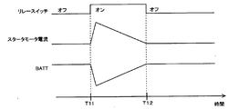
- FIG. 6 is a time chart showing changes in the current of the starter motor 55 and the voltage BATT of the battery 51 when the starter motor 55 is driven by normal control.
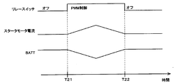
- FIG. 7 is a time chart showing changes in the current of the starter motor 55 and the voltage BATT of the battery 51 when the starter motor 55 is driven by PWM control.
- the first and second relay switches 95 and 97 are turned on at time T11 when the starter motor 55 starts to be driven. Thereafter, the first and second relay switches 95 and 97 are turned on continuously.
- the start-up speed (slew rate) of the current of the starter motor 55 is large, and the current of the starter motor 55 rapidly increases immediately after the start of driving.
- the voltage BATT of the battery 51 also suddenly decreases, and the voltage of the battery 51 greatly decreases.
- the load on the starter motor 55 decreases as the engine 57 rotates, the voltage BATT of the battery 51 gradually increases.
- the first and second relay switches 95 and 97 are turned off, and the starter motor 55 is stopped.
- the microcomputer 2 is prevented from being reset and the engine 57 can be started.
- the PWM signal is stopped and the starter motor 55 is stopped.
- the microcomputer 2 when the voltage of the battery 51 decreases and the voltage VCC of the power source of the microcomputer 2 becomes less than the minimum operating voltage Vt of the microcomputer 2, The microcomputer 2 is reset. On the other hand, the voltage drop information is stored in the storage unit 3. For this reason, the microcomputer 2 after reset can grasp
- the power supply voltage of the storage unit 3 may be directly supplied from the battery 51, or a nonvolatile memory such as an EEPROM or a flash memory may be adopted as the storage unit 3.
- the voltage drop information can be stored in the storage unit 3 regardless of whether the ignition switch is on or off.
- the second relay coil 96 is energized by PWM control, The start-up speed of the current of the starter motor 55 may be suppressed.
- the voltage drop information may be deleted from the storage unit 3 when the battery 51 is replaced.
- the storage unit 3 is composed of a logic circuit capable of storing 1-bit information.
- a memory having a relatively large storage capacity may be employed.
- the storage unit 3 includes only one logic circuit capable of storing 1-bit information as in the above embodiment, the storage unit 3 can be realized at a very low cost.
Landscapes
- Engineering & Computer Science (AREA)
- Chemical & Material Sciences (AREA)
- Combustion & Propulsion (AREA)
- Mechanical Engineering (AREA)
- General Engineering & Computer Science (AREA)
- Control Of Vehicle Engines Or Engines For Specific Uses (AREA)
Abstract
車両に搭載されるアイドリングストップ装置は、マイクロコンピュータと、検知手段と、記憶手段と、制御手段とを備える。マイクロコンピュータは、所定の停止条件が成立したときに前記車両のエンジンを自動で停止するとともに、所定の始動条件が成立したときに前記エンジンのスタータモータを自動で始動する。検知手段は、前記車両のバッテリの電圧を降圧して得られる前記マイクロコンピュータの駆動電圧が閾値未満であるかを検知する。記憶手段は、前記マイクロコンピュータの状態に関わらず、前記駆動電圧が前記閾値未満であると前記検知手段が検知したことを示す情報を記憶する。制御手段は、前記記憶手段に前記情報が記憶されている状態で前記マイクロコンピュータが前記スタータモータを始動する際に、該スタータモータを駆動する電流の増加速度を抑制する。
Description
本発明は、車両のエンジンを自動で停止/始動するアイドリングストップ技術に関する。
近年、燃料節減や排ガス削減などを目的とし、信号待ちなどの比較的短時間の車両の停車中において、車両のエンジンを自動で停止/始動するアイドリングストップ装置が実用化されている。例えば日本国特許出願公開2009-13953号公報に記載のアイドリングストップ装置を備えた車両においては、走行状態からブレーキが踏まれて停止状態となるなどの停止条件が成立するとエンジンが自動で停止され、そのエンジン停止中にブレーキがリリースされるなどの始動条件が成立するとエンジンが自動で始動されるようになっている。
車両のエンジンを始動するためのスタータモータを駆動する電力は車両が備えるバッテリから供給される。エンジンの始動のためにスタータモータが必要とする電力は非常に大きいことから、バッテリの電圧が低下している場合にアイドリングストップ機能によるエンジンの停止/始動を繰り返すと、バッテリの電圧がさらに低下し、エンジンが始動できないなどの支障をきたす可能性がある。したがって、バッテリが劣化してその電圧が低下しているような場合は、アイドリングストップ機能でエンジンを始動可能とするために、バッテリの電圧の低下を防止する対策が必要となる。
ところで、前述のように、エンジンの始動のためにスタータモータが必要とする電力は非常に大きいため、エンジンの始動の際にはバッテリの電圧が大きく低下する。このため例えば、アイドリングストップ装置が備えるマイクロコンピュータに、ユーザのスタートスイッチの操作によるエンジンの始動の際におけるバッテリの電圧を監視させる。そして、このときのバッテリの電圧が所定の閾値よりも低下するような場合は、それ以降のアイドリングストップ機能でのエンジンの始動の際に、マイクロコンピュータがバッテリの電圧の低下を防止する対策を実行するように構成することが考えられる。
しかしながら、マイクロコンピュータを動作させるための電力もバッテリから供給されるため、エンジンの始動の際に、バッテリの電圧がマイクロコンピュータが動作可能な電圧未満まで大きく低下するような場合は、マイクロコンピュータ自体が動作できずにリセットされてしまう。このようにしてリセットされ再起動したマイクロコンピュータは、リセットの原因やリセット前のバッテリの電圧を把握できない。マイクロコンピュータは、電源の電圧低下のほか、例えば、暴走状態となった場合などにおいてもリセットされるが、このようなリセットの原因を把握できない。
このため、バッテリの電圧が大きく低下してリセットされた場合においても、リセット後のマイクロコンピュータは、バッテリの電圧の低下を防止する対策をせずに、アイドリングストップ機能によるエンジンの始動を実行してしまう。その結果、マイクロコンピュータのリセットが再発生して、エンジンが始動できなくなるおそれがある。
本発明は、上記課題に鑑みてなされたものであり、マイクロコンピュータのリセット後においてもバッテリの電圧低下を把握して、エンジンを始動する際にバッテリの電圧の大きな低下を防止できる技術を提供することを目的とする。
上記課題を解決するため、本発明によれば、以下に列挙するものが提供され得る。
(1):車両に搭載されるアイドリングストップ装置であって、
所定の停止条件が成立したときに前記車両のエンジンを自動で停止するとともに、所定の始動条件が成立したときに前記エンジンのスタータモータを自動で始動するマイクロコンピュータと、
前記車両のバッテリの電圧を降圧して得られる前記マイクロコンピュータの駆動電圧が閾値未満であるかを検知する検知手段と、
前記マイクロコンピュータの状態に関わらず、前記駆動電圧が前記閾値未満であると前記検知手段が検知したことを示す情報を記憶する記憶手段と、
前記記憶手段に前記情報が記憶されている状態で前記マイクロコンピュータが前記スタータモータを始動する際に、該スタータモータを駆動する電流の増加速度を抑制する制御手段と、
を備えるアイドリングストップ装置。
(2):前記制御手段は、時間の経過とともにデューティ比が高くなるPWM信号を発生し、該PWM信号のオン期間のみ、前記バッテリに前記スタータモータに電力を供給させる、(1)に記載のアイドリングストップ装置。
(3):前記記憶手段は、1ビットの情報を記憶可能な論理回路である、(1)または(2)に記載のアイドリングストップ装置。
(4):所定の停止条件が成立したときに車両のエンジンを自動で停止するとともに、所定の始動条件が成立したときに前記エンジンのスタータモータを自動で始動するマイクロコンピュータが搭載された車両のアイドリングストップ制御方法であって、
前記車両のバッテリの電圧を降圧して得られる前記マイクロコンピュータの駆動電圧が閾値未満であるかを検知し、
前記マイクロコンピュータの状態に関わらず、前記駆動電圧が前記閾値未満であると前記検知手段が検知したことを示す情報を記憶手段に記憶し、
前記記憶手段に前記情報が記憶されている状態で前記マイクロコンピュータが前記スタータモータを始動する際に、該スタータモータを駆動する電流の増加速度を抑制する、
アイドリングストップ制御方法。
前記車両のバッテリの電圧を降圧して得られる前記マイクロコンピュータの駆動電圧が閾値未満であるかを検知し、
前記マイクロコンピュータの状態に関わらず、前記駆動電圧が前記閾値未満であると前記検知手段が検知したことを示す情報を記憶手段に記憶し、
前記記憶手段に前記情報が記憶されている状態で前記マイクロコンピュータが前記スタータモータを始動する際に、該スタータモータを駆動する電流の増加速度を抑制する、
アイドリングストップ制御方法。
(5):更に時間の経過とともにデューティ比が高くなるPWM信号を発生し、
前記PWM信号のオン期間のみ、前記バッテリに前記スタータモータに電力を供給させる、(4)に記載のアイドリングストップ制御方法。
前記PWM信号のオン期間のみ、前記バッテリに前記スタータモータに電力を供給させる、(4)に記載のアイドリングストップ制御方法。
上記の構成によれば、マイクロコンピュータの駆動電圧が閾値未満となった場合に、マイクロコンピュータがリセットされたとしても電圧が低下した事実を示す情報が記憶手段に記憶される。このため、リセット後のマイクロコンピュータは、当該情報に基づいてバッテリの電圧低下を把握できる。そして以降、エンジンを始動する際にスタータモータを駆動する電流の増加速度を抑制することから、エンジンを始動する際にバッテリの電圧の大きな低下を防止できる。
以下、添付の図面を参照しつつ本発明の実施の形態について詳細に説明する。
<1.構成>
図1は、本実施の形態のアイドリングストップ装置1とその周辺要素との構成を示すブロック図である。このアイドリングストップ装置1は、例えば、自動車などの車両に搭載され、信号待ちなどの比較的短時間の車両の停車中において、車両が備えるエンジン57を自動で停止/始動する機能を有している。
図1は、本実施の形態のアイドリングストップ装置1とその周辺要素との構成を示すブロック図である。このアイドリングストップ装置1は、例えば、自動車などの車両に搭載され、信号待ちなどの比較的短時間の車両の停車中において、車両が備えるエンジン57を自動で停止/始動する機能を有している。
アイドリングストップ装置1が搭載される車両は、車両各部の電気負荷に電力を供給するバッテリ51を備えている。このバッテリ51には電源ライン91が接続され、この電源ライン91にはユーザが操作可能なイグニッションスイッチ92が設けられている。イグニッションスイッチ92がオンとされると、電源ライン91を介してバッテリ51からアイドリングストップ装置1に電力が供給される。また、イグニッションスイッチ92がオンとされると、車両に搭載される各種の電気負荷に対しても、バッテリ51から電源ライン91を介して電力が供給される。
エンジン57は、スタータモータ55を駆動することで始動する。このスタータモータ55は、第1リレースイッチ95を介して電源ライン91に接続されている。このため、第1リレースイッチ95がオンとされると、バッテリ51からスタータモータ55に電力が供給される。これにより、スタータモータ55が駆動し、エンジン57が始動する。
第1リレースイッチ95は、対応する第1リレーコイル94を通電することでオンとされる。この第1リレーコイル94は、その上流側に設けられた第2リレースイッチ97をオンとした場合、あるいは、ユーザが操作可能なスタートスイッチ93をオンとした場合に通電する。ユーザが車両に乗車した際には、このスタートスイッチ93をオンとする操作に応答してスタータモータ55が駆動し、エンジン57が始動することになる。
また、第2リレースイッチ97は、対応する第2リレーコイル96を通電することでオンとされる。したがって、第2リレーコイル96を通電すれば、第2リレースイッチ97がオンとなって、第1リレーコイル94に電流が流れる。その結果、第1リレースイッチ95がオンとなり、スタータモータ55に電流が流れて、エンジン57が始動することになる。
第2リレーコイル96は、第1リレーコイル94と比較して、小さな電流の通電で対応するリレースイッチ(この場合は、第2リレースイッチ97)をオンとすることが可能である。このため、第1リレーコイル94を直接通電するよりも、第2リレーコイル96を通電したほうが、比較的小さな電流の信号で、エンジン57を始動できる。
また、バッテリ51は、発電機であるオルタネータ52によって充電される。オルタネータ52は、エンジン57から伝達される機械的運動エネルギーを交流の電力へと変換し、さらにダイオードを含む整流器で直流の電力へと整流する。発電した電力は、電源ライン91を介してバッテリ51に蓄積される。オルタネータ52が発電する際には発電の目標となる目標電圧が設定され、電源ライン91の電圧が目標電圧となるようにオルタネータ52が発電を行う。
アイドリングストップ装置1は、ECU(Electronic Control Unit)として構成されており、主たる構成要素としてマイクロコンピュータ2を備えている。マイクロコンピュータ2は、CPU21、RAM22及びROM23を備えている。マイクロコンピュータ2が備える各種機能は、ROM23に予め記録されたプログラムに従ってCPU21が演算処理を行うことで実現される。このようなマイクロコンピュータ2が備える機能に、アイドリングストップ機能が含まれている。
アイドリングストップ機能は、車両の走行状態に応じて、車両のエンジン57を自動で停止/始動する機能である。車両の走行状態を示す信号は、車両に設けられた各種センサからインターフェイス18を介してマイクロコンピュータ2に入力される。具体的には、車速センサから車両の速度、シフトセンサからシフトレバーのポジション、アクセルセンサからアクセルの操作内容、ブレーキセンサからブレーキの操作内容がそれぞれ信号として入力される。
これらの走行状態を示す信号に基づいて所定の停止条件が成立した場合は、アイドリングストップ機能によりエンジン57が停止される。例えば、「車両の速度が0」、「シフトレバーが”D”または”N”」、「アクセルの操作なし」、及び、「ブレーキの操作あり」の各種条件をすべて満足した場合に、停止条件が成立したと判断される。
アイドリングストップ機能でエンジン57を停止する際には、マイクロコンピュータ2が、エンジン57を制御するエンジンECU56に対して所定の停止信号を送信する。エンジンECU56は、この信号に応答してエンジン57を停止する。
また、アイドリングストップ機能によるエンジン57の停止中に、走行状態を示す信号に基づいて所定の始動条件が成立した場合は、アイドリングストップ機能によりエンジン57が自動で始動される。例えば、「シフトレバーが”D”」、「アクセルの操作あり」、及び、「ブレーキの操作なし」の各種条件をすべて満足した場合に、始動条件が成立したと判断される。
アイドリングストップ機能でエンジン57を始動する際には、マイクロコンピュータ2が、アイドリングストップ装置1が備えるスタータ制御回路16に対して所定の始動信号を送信する。スタータ制御回路16は、この信号に応答して第2リレーコイル96を通電して、スタータモータ55を駆動させる。
スタータ制御回路16が、第2リレーコイル96を通電する制御として、2種類の制御がある。一つは、第2リレーコイル96を単純に通電する通常制御であり、他の一つは、PWM(Pulse Width Modulation)信号のオン期間のみ通電するPWM制御である。スタータ制御回路16は、このPWM制御のためのPWM信号を発生するPWM回路17を備えている。通常制御とPWM制御とのいずれで制御するかは、バッテリの劣化状態に応じてマイクロコンピュータ2が選択することになるが、詳細は後述する。
また、アイドリングストップ装置1は、マイクロコンピュータ2への電源供給回路として、入力電圧を一定電圧へ降圧するレギュレータ11を備えている。レギュレータ11は、例えば、スイッチングレギュレータとシリーズレギュレータとを組み合わせて構成される。
マイクロコンピュータ2の電力は車両のバッテリ51から供給されるが、マイクロコンピュータ2の電源の電圧の理想値は例えば5Vであるのに対し、バッテリ51の通常電圧は例えば12Vである。このため、アイドリングストップ装置1では、バッテリ51の電圧BATTを、レギュレータ11で降圧してマイクロコンピュータ2の電源の電圧VCCを得るようになっている。
なお、レギュレータ11は、入力電圧を上限とする範囲で出力電圧を調整するものであり、入力電圧が一定とすべき目的の電圧より低下すれば、レギュレータ11の出力電圧も目的の電圧より低下することになる。したがって、バッテリ51が劣化している場合においては、バッテリの電圧BATTが低下すれば、それにつれて、レギュレータ11で降圧して得られるマイクロコンピュータ2の電源の電圧VCCも低下する。
また、アイドリングストップ装置1は、マイクロコンピュータ2をリセットするための回路として、減電圧検知部13と、リセット部14と、暴走検知部15とを備えている。
減電圧検知部13は、レギュレータ11からマイクロコンピュータ2への電力供給線に接続され、マイクロコンピュータ2の電源の電圧(駆動電圧)VCCを監視する。そして本発明の検知手段として機能し、マイクロコンピュータ2の電源の電圧VCCが、所定の閾値(例えばマイクロコンピュータ2が動作可能な最低動作電圧Vt)未満となった場合は、リセット部14にリセットすべきことを示す指示信号を出力する。マイクロコンピュータ2の最低動作電圧Vtは例えば3.9Vである。減電圧検知部13は、例えば、電圧VCCと最低動作電圧Vtとを比較するコンパレータで構成される。
暴走検知部15は、マイクロコンピュータ2がフリーズするなどの暴走状態に陥っていないかを検出する。暴走検知部15は、例えば、マイクロコンピュータ2のウォッチドッグタイマの動作信号を監視し、規則的な信号が検知されなかった場合に、マイクロコンピュータ2が暴走状態であると判断する。暴走状態となると、マイクロコンピュータ2はリセットしないとその機能を回復できない。このため、暴走検知部15は、リセット部14にリセットすべきことを示す指示信号を出力する。
リセット部14は、マイクロコンピュータ2に対してリセットを指示するリセット信号を出力するものである。リセット信号は、通常は”H”であり、”L”となることでマイクロコンピュータ2に対してリセットが指示される。リセット部14は、減電圧検知部13及び暴走検知部15のいずれかからリセットすべきことを示す指示信号が入力されると、リセット信号を”L”とする。マイクロコンピュータ2はこのリセット信号を常時に監視しており、リセット信号が”L”となるとリセットする。すなわち、マイクロコンピュータ2は、一旦動作停止した後、再起動することになる。
アイドリングストップ装置1は、マイクロコンピュータ2の電源の電圧VCCが最低動作電圧Vt未満となった場合に、電圧VCCが最低動作電圧Vt未満となったことを示す情報(以下、「電圧低下情報」という。)を記憶する記憶部3を備えている。減電圧検知部13から出力される指示信号は、記憶部3にも入力される。すなわち、マイクロコンピュータ2の電源の電圧VCCが最低動作電圧Vt未満となった場合は、指示信号により記憶部3にその旨が通知され、それに応答して電圧低下情報が記憶部3に記憶されることになる。
記憶部3は本発明の記憶手段として機能し、例えば、1ビットの情報を記憶可能な論理回路であるフリップフロップで構成される。記憶部3の最低動作電圧は、マイクロコンピュータ2の最低動作電圧Vt(例えば、3.6V)よりも低く、例えば1.6Vとなっている。すなわち、記憶部3は、その電源電圧が、マイクロコンピュータ2の最低動作電圧Vtよりも低くなったとしても、その記憶内容を保持できる。このため、記憶部3は、マイクロコンピュータ2の状態に関わらず、マイクロコンピュータ2のリセット中においても電圧低下情報を記憶できる。
バッテリ51の電圧が低下して電圧VCCが最低動作電圧Vt未満となると、マイクロコンピュータ2はリセットされるが、その一方で記憶部3に電圧低下情報が記憶される。リセット後のマイクロコンピュータ2は、この記憶部3に電圧低下情報が記憶されていることに基づいて、リセット前に電源の電圧VCCが最低動作電圧Vt未満となったことを把握することが可能となる。
<2.リセット処理>
バッテリ51の電圧が大きく低下してマイクロコンピュータ2がリセットされる現象は、スタータモータ55が必要とする電力が非常に大きいことから、エンジン57を始動する際に発生する。以下、ユーザのスタートスイッチ93の操作によりエンジン57を始動する場合における、アイドリングストップ装置1の処理について説明する。図2は、このアイドリングストップ装置1の処理の流れを示す図である。この処理の開始時点は、ユーザが車両に乗車した直後であり、アイドリングストップ装置1は起動しているが、エンジン57は始動していない。
バッテリ51の電圧が大きく低下してマイクロコンピュータ2がリセットされる現象は、スタータモータ55が必要とする電力が非常に大きいことから、エンジン57を始動する際に発生する。以下、ユーザのスタートスイッチ93の操作によりエンジン57を始動する場合における、アイドリングストップ装置1の処理について説明する。図2は、このアイドリングストップ装置1の処理の流れを示す図である。この処理の開始時点は、ユーザが車両に乗車した直後であり、アイドリングストップ装置1は起動しているが、エンジン57は始動していない。
まず、エンジン57の始動中にマイクロコンピュータ2をリセットすべき条件が成立したか否かが判断される。具体的には、減電圧検知部13により、マイクロコンピュータ2の電源の電圧VCCが、マイクロコンピュータ2の最低動作電圧Vt未満となっていないかが判断される(ステップS11)。これとともに、暴走検知部15により、マイクロコンピュータ2が暴走状態に陥っていないかが判断される(ステップS12)。電圧VCCが最低動作電圧Vt以上であり(ステップS11にてNo)、かつ、マイクロコンピュータ2が暴走状態でないままエンジン57が完爆(完全に始動)した場合は(ステップS12にてNo)、処理が終了する。
また、マイクロコンピュータ2の電源の電圧VCCが最低動作電圧Vt未満となった場合は(ステップS11にてYes)、減電圧検知部13からリセット部14に指示信号が出力される。また、この指示信号は記憶部3にも入力され、これに応答して記憶部3において電圧低下情報が記憶される(ステップS13)。
一方、マイクロコンピュータ2が暴走状態となった場合にも(ステップS12にてYes)、減電圧検知部13からリセット部14に指示信号が出力される。
リセット部14は、減電圧検知部13及び暴走検知部15のいずれかから指示信号が入力されると、リセット信号を”L”とする。マイクロコンピュータ2は、このリセット信号が”L”となったことに応答してリセットされる(ステップS14)。記憶部3に電圧低下情報が記憶されている場合は、このようなマイクロコンピュータ2のリセット中においても記憶部3の電圧低下情報の記憶が保持される。
その後、マイクロコンピュータ2は再起動する。再起動したマイクロコンピュータ2は、記憶部3に電圧低下情報が記憶されているか否かに基づいて、リセットされた原因を把握することが可能である。すなわち、記憶部3に電圧低下情報が記憶されていない場合は暴走状態となったことに起因してリセットされたと判断できる。一方、記憶部3に電圧低下情報が記憶されていた場合は電圧VCCが最低動作電圧Vt未満となったことに起因してリセットされたと判断できる。
図3は、エンジン57の始動時にバッテリ51の電圧が低下する場合における各種信号の変化を示すタイムチャートである。このチャートの開始時点では、イグニッションスイッチ92はオフとされ、エンジン57は始動されていない。
まず、時点T1において、ユーザの操作によりイグニッションスイッチ92がオンとされる。これにより、バッテリ51からアイドリングストップ装置1に電力が供給され、マイクロコンピュータ2が起動する。
次に、時点T2において、ユーザの操作によりスタートスイッチ93がオンとなりスタータモータ55が駆動される。このスタータモータ55の駆動に伴ってバッテリ51の電圧BATTが低下する。これにより、電源ライン91の電圧が低下する。さらに、バッテリ51が劣化している場合は、マイクロコンピュータ2の電源の電圧VCCも低下する。
このようにして、マイクロコンピュータ2の電源の電圧VCCが低下して、時点T3において、マイクロコンピュータ2の最低動作電圧Vt未満となると、減電圧検知部13がこれを検知し、指示信号を発生する(”H”とする)。これを受けて、リセット部14は、リセット信号を”L”とし、マイクロコンピュータ2はリセットのために動作を停止する。これとともに、減電圧検知部13からの指示信号が記憶部3にも入力され、記憶部3において電圧低下情報が記憶される。以降、マイクロコンピュータ2の状態に関わらず、記憶部3において電圧低下情報が保持される。
その後、エンジン57の回転に伴いスタータモータ55の負荷が小さくなると、バッテリ51の電圧BATTが徐々に上昇していく。このため、電源ライン91の電圧や、マイクロコンピュータ2の電源の電圧VCCも上昇する。そして、マイクロコンピュータ2の電源の電圧VCCが上昇して、時点T4において、マイクロコンピュータ2の最低動作電圧Vt以上となると、減電圧検知部13は指示信号を停止する(”L”とする)。これを受けて、リセット部14はリセット信号を”H”とし、マイクロコンピュータ2が再起動することになる。以降、再起動したマイクロコンピュータ2は、記憶部3に電圧低下情報が記憶されていることに基づいて、バッテリ51が劣化してその電圧が通常よりも低下した状態となっていることを把握できる。エンジン57が完爆すると、スタータモータ55は停止されることになる(時点T5)。
<3.アイドリングストップ処理>
リセット後のマイクロコンピュータ2は、記憶部3に電圧低下情報が記憶されている場合は、アイドリングストップ機能を維持できるように、アイドリングストップ機能でエンジン57を始動する際にバッテリ51の電圧の低下を防止する対策を実行する。具体的には、マイクロコンピュータ2は、スタータ制御回路16に、通常制御ではなくPWM制御で第2リレーコイル96を通電させることになる。以下、このような処理について説明する。
リセット後のマイクロコンピュータ2は、記憶部3に電圧低下情報が記憶されている場合は、アイドリングストップ機能を維持できるように、アイドリングストップ機能でエンジン57を始動する際にバッテリ51の電圧の低下を防止する対策を実行する。具体的には、マイクロコンピュータ2は、スタータ制御回路16に、通常制御ではなくPWM制御で第2リレーコイル96を通電させることになる。以下、このような処理について説明する。
図4は、アイドリングストップ装置1のアイドリングストップ機能に係る処理の流れを示す図である。この処理の開始時点では、エンジン57は始動しているものとする。
まず、マイクロコンピュータ2は、入力される走行状態を示す信号に基づいて停止条件が成立したか否かを判断する(ステップS21)。そして、停止条件が成立した場合は、マイクロコンピュータ2は、エンジンECU56に対して停止信号を送信して、エンジン57を停止させる(ステップS22)。
その後、マイクロコンピュータ2は、入力される走行状態を示す信号に基づいて始動条件が成立したか否かを判断する(ステップS23)。始動条件が成立した場合は、マイクロコンピュータ2は、続いて、記憶部3に電圧低下情報が記憶されているか否かを判断する(ステップS24)。
記憶部3に電圧低下情報が記憶されていない場合は、バッテリ51は正常である。この場合は、マイクロコンピュータ2はスタータ制御回路16に信号を送出し、スタータ制御回路16に通常制御で第2リレーコイル96を通電させ、スタータモータ55を駆動させる(ステップS26)。この場合は、第2リレーコイル96を継続して通電し、その通電している間において第1及び第2リレースイッチ95,97が単純にオンとされる。バッテリ51は正常であるため、他の電気負荷に大きな影響を与えることなく、スタータモータ55が駆動してエンジン57が始動する。
一方、記憶部3に電圧低下情報が記憶されている場合は、バッテリ51が劣化している。この場合は、マイクロコンピュータ2はスタータ制御回路16に信号を送出し、スタータ制御回路16にPWM制御で第2リレーコイル96を通電させ、スタータモータ55を駆動させる(ステップS25)。すなわちスタータ制御回路16は、本発明の制御手段として機能する。
PWM回路17が発生するPWM信号は、図5に示すように、デューティ比(信号周期Tにおけるオン期間の割合)は一定ではなく、PWM制御の開始からの時間の経過とともに徐々に高く変化するようになっている。このようなPWM信号のオン期間のみ第2リレーコイル96が通電することから、PWM信号のオン期間のみ第1及び第2リレースイッチ95,97がオンとされる。したがって、PWM信号のオン期間のみ、バッテリ51からスタータモータ55に電力が供給されることになる。このような制御により、スタータモータ55に徐々に電流を流すことができ、スタータモータ55の電流の立ち上がりの速さ(i/t)(スルーレートあるいは増加速度)を抑制することができる。
図6は、通常制御でスタータモータ55を駆動させた場合のスタータモータ55の電流、及び、バッテリ51の電圧BATTの変化を示すタイムチャートである。一方、図7は、PWM制御でスタータモータ55を駆動させた場合のスタータモータ55の電流、及び、バッテリ51の電圧BATTの変化を示すタイムチャートである。
通常制御の場合は、図6に示すように、スタータモータ55の駆動が開始される時点T11で第1及び第2リレースイッチ95,97がオンとされる。その後も継続して、第1及び第2リレースイッチ95,97はオンとされる。スタータモータ55の電流の立ち上がりの速さ(スルーレート)は大きく、その駆動開始の直後からスタータモータ55の電流は急激に上昇する。これに伴い、バッテリ51の電圧BATTも急激に低下して、バッテリ51の電圧が大きく低下することになる。その後、エンジン57の回転に伴いスタータモータ55の負荷が小さくなると、バッテリ51の電圧BATTが徐々に上昇する。時点T12でエンジン57が完爆すると、第1及び第2リレースイッチ95,97がオフとなり、スタータモータ55が停止される。
このように通常制御の場合は、バッテリ51の電圧BATTが大きく低下するため、バッテリ51が劣化している場合は、マイクロコンピュータ2の電源の電圧VCCが低下することがある。その結果、マイクロコンピュータ2がリセットされ、エンジン57が始動できない可能性がある。
これに対して、PWM制御の場合は、図7に示すように、時点T21でスタータモータ55の駆動が開始されると、時間の経過とともにデューティ比が徐々に高くなるPWM信号がPWM回路17で発生され、このPWM信号のオン期間のみ第1及び第2リレースイッチ95,97がオンとされる(図5参照。)。すなわち、PWM信号のオン期間のみバッテリ51からスタータモータ55に電力が供給される。このため、スタータモータ55の電流の立ち上がりの速さ(スルーレート)を抑制することができる。したがって、バッテリ51の電圧の急激な低下が発生せず、バッテリ51の電圧の大きな低下を防止することができる。その結果、エンジン57の完爆までに多少の時間がかかるものの、マイクロコンピュータ2のリセットの発生が防止され、エンジン57を始動することができる。時点T22でエンジン57が完爆すると、PWM信号が停止され、スタータモータ55が停止される。
以上のように、本実施の形態のアイドリングストップ装置1においては、バッテリ51の電圧が低下して、マイクロコンピュータ2の電源の電圧VCCがマイクロコンピュータ2の最低動作電圧Vt未満となった場合に、マイクロコンピュータ2がリセットされる。その一方で、電圧低下情報が記憶部3に記憶される。このため、リセット後のマイクロコンピュータ2は、電圧低下情報に基づいてバッテリ51の電圧が低下したことを把握できる。そして以降、マイクロコンピュータ2は、アイドリングストップ機能でエンジン57を始動する際に、PWM制御で第2リレーコイル96を通電させ、スタータモータ55の電流の立ち上がりの速さを抑制する。これにより、バッテリ51の電圧の大きな低下を防止でき、アイドリングストップ機能を維持することができる。
<4.変形例>
以上、本発明の実施の形態について説明してきたが、この発明は上記実施の形態に限定されるものではなく様々な変形が可能である。以下では、このような変形例について説明する。上記実施の形態で説明した形態及び以下で説明する形態を含む全ての形態は、適宜に組み合わせ可能である。
以上、本発明の実施の形態について説明してきたが、この発明は上記実施の形態に限定されるものではなく様々な変形が可能である。以下では、このような変形例について説明する。上記実施の形態で説明した形態及び以下で説明する形態を含む全ての形態は、適宜に組み合わせ可能である。
記憶部3の電源電圧をバッテリ51から直接的に供給するようにしたり、EEPROMやフラッシュメモリなどの不揮発性メモリを記憶部3として採用してもよい。この場合は、イグニッションスイッチのオン/オフに関わらず、電圧低下情報を記憶部3に記憶させることができる。この場合、ユーザのスタートスイッチ93の操作に応答してエンジン57を始動する場合においても、電圧低下情報が記憶部3に記憶されていれば、PWM制御で第2リレーコイル96を通電させて、スタータモータ55の電流の立ち上がりの速さを抑制するようにしてもよい。電圧低下情報は、バッテリ51の交換時に記憶部3から消去するようにすればよい。
また、上記実施の形態では、記憶部3は1ビットの情報を記憶可能な論理回路で構成されていたが、比較的大きな記憶容量を有するメモリなどを採用してもよい。ただし、上記実施の形態のように、記憶部3を1ビットの情報を記憶可能な論理回路を1つのみ備えて構成すれば、記憶部3を非常に低コストで実現することができる。
また、上記実施の形態では、プログラムに従ったCPUの演算処理によってソフトウェア的に各種の機能が実現されると説明したが、これら機能のうちの一部は電気的なハードウェア回路により実現されてもよい。また逆に、ハードウェア回路によって実現されるとした機能のうちの一部は、ソフトウェア的に実現されてもよい。
本出願は、2010年3月15日に提出された日本特許出願2010-056956に基づくものであり、その内容はここに参照として取り込まれる。
Claims (5)
- 車両に搭載されるアイドリングストップ装置であって、
所定の停止条件が成立したときに前記車両のエンジンを自動で停止するとともに、所定の始動条件が成立したときに前記エンジンのスタータモータを自動で始動するマイクロコンピュータと、
前記車両のバッテリの電圧を降圧して得られる前記マイクロコンピュータの駆動電圧が閾値未満であるかを検知する検知手段と、
前記マイクロコンピュータの状態に関わらず、前記駆動電圧が前記閾値未満であると前記検知手段が検知したことを示す情報を記憶する記憶手段と、
前記記憶手段に前記情報が記憶されている状態で前記マイクロコンピュータが前記スタータモータを始動する際に、該スタータモータを駆動する電流の増加速度を抑制する制御手段と、
を備えるアイドリングストップ装置。 - 請求項1に記載のアイドリングストップ装置において、
前記制御手段は、時間の経過とともにデューティ比が高くなるPWM信号を発生し、該PWM信号のオン期間のみ、前記バッテリに前記スタータモータに電力を供給させるアイドリングストップ装置。 - 請求項1または2に記載のアイドリングストップ装置において、
前記記憶手段は、1ビットの情報を記憶可能な論理回路であるアイドリングストップ装置。 - 所定の停止条件が成立したときに車両のエンジンを自動で停止するとともに、所定の始動条件が成立したときに前記エンジンのスタータモータを自動で始動するマイクロコンピュータが搭載された車両のアイドリングストップ制御方法であって、
前記車両のバッテリの電圧を降圧して得られる前記マイクロコンピュータの駆動電圧が閾値未満であるかを検知し、
前記マイクロコンピュータの状態に関わらず、前記駆動電圧が前記閾値未満であると前記検知手段が検知したことを示す情報を記憶手段に記憶し、
前記記憶手段に前記情報が記憶されている状態で前記マイクロコンピュータが前記スタータモータを始動する際に、該スタータモータを駆動する電流の増加速度を抑制する、
アイドリングストップ制御方法。 - 請求項4に記載のアイドリングストップ制御方法において、更に
時間の経過とともにデューティ比が高くなるPWM信号を発生し、
前記PWM信号のオン期間のみ、前記バッテリに前記スタータモータに電力を供給させる、アイドリングストップ制御方法。
Priority Applications (2)
| Application Number | Priority Date | Filing Date | Title |
|---|---|---|---|
| US13/583,721 US9014942B2 (en) | 2010-03-15 | 2011-03-10 | Idling stop device and idling stop control method |
| EP11756165.4A EP2549085A4 (en) | 2010-03-15 | 2011-03-10 | Idling stop apparatus and idling stop control method |
Applications Claiming Priority (2)
| Application Number | Priority Date | Filing Date | Title |
|---|---|---|---|
| JP2010056956A JP2011190734A (ja) | 2010-03-15 | 2010-03-15 | アイドリングストップ装置、及び、エンジン始動方法 |
| JP2010-056956 | 2010-03-15 |
Publications (1)
| Publication Number | Publication Date |
|---|---|
| WO2011114979A1 true WO2011114979A1 (ja) | 2011-09-22 |
Family
ID=44649074
Family Applications (1)
| Application Number | Title | Priority Date | Filing Date |
|---|---|---|---|
| PCT/JP2011/055606 Ceased WO2011114979A1 (ja) | 2010-03-15 | 2011-03-10 | アイドリングストップ装置およびアイドリングストップ制御方法 |
Country Status (4)
| Country | Link |
|---|---|
| US (1) | US9014942B2 (ja) |
| EP (1) | EP2549085A4 (ja) |
| JP (1) | JP2011190734A (ja) |
| WO (1) | WO2011114979A1 (ja) |
Cited By (2)
| Publication number | Priority date | Publication date | Assignee | Title |
|---|---|---|---|---|
| CN103225619A (zh) * | 2012-01-30 | 2013-07-31 | 建准电机工业股份有限公司 | 风扇转速控制方法及其装置 |
| WO2013111587A3 (en) * | 2012-01-24 | 2013-12-05 | Hitachi Koki Co., Ltd. | Hand held engine powered tool with an electric starter and a recoil starter |
Families Citing this family (6)
| Publication number | Priority date | Publication date | Assignee | Title |
|---|---|---|---|---|
| JP6062324B2 (ja) * | 2013-06-14 | 2017-01-18 | 日立オートモティブシステムズ株式会社 | エンジン始動装置およびエンジン始動制御方法 |
| FR3009345B1 (fr) * | 2013-08-01 | 2015-09-04 | Valeo Equip Electr Moteur | Procede et dispositif de commande d'un alterno-demarreur de vehicule automobile, et alterno-demarreur correspondant |
| DE102013223316A1 (de) * | 2013-11-15 | 2015-05-21 | Robert Bosch Gmbh | Überspannungsschutz für Kraftfahrzeugbordnetz bei Lastabwurf |
| JP2017166434A (ja) * | 2016-03-17 | 2017-09-21 | 株式会社オートネットワーク技術研究所 | 停止制御回路 |
| DE102019130431A1 (de) * | 2019-11-12 | 2021-05-12 | Seg Automotive Germany Gmbh | Verfahren zum Bestimmen eines Ladezustands einer Fahrzeugbatterie eines Fahrzeugs |
| TWI776621B (zh) * | 2021-08-03 | 2022-09-01 | 三陽工業股份有限公司 | 可助力調控怠速之方法 |
Citations (6)
| Publication number | Priority date | Publication date | Assignee | Title |
|---|---|---|---|---|
| JPH07111710A (ja) * | 1993-10-08 | 1995-04-25 | Honda Motor Co Ltd | 電動走行車両のハイブリッド電源装置 |
| JP2002031021A (ja) * | 2000-07-19 | 2002-01-31 | Honda Motor Co Ltd | エンジン発電システムおよびそのコントローラ |
| JP2005237149A (ja) * | 2004-02-20 | 2005-09-02 | Toyota Motor Corp | 車両用電源装置 |
| JP2007290478A (ja) * | 2006-04-24 | 2007-11-08 | Toyota Motor Corp | 負荷駆動装置およびそれを備えた車両 |
| JP2009013953A (ja) | 2007-07-09 | 2009-01-22 | Toyota Motor Corp | エンジンの自動停止始動制御装置 |
| JP2010056956A (ja) | 2008-08-28 | 2010-03-11 | Sanyo Electric Co Ltd | 報知方法および無線装置 |
Family Cites Families (11)
| Publication number | Priority date | Publication date | Assignee | Title |
|---|---|---|---|---|
| JPH0763115A (ja) | 1993-08-30 | 1995-03-07 | Yamaha Motor Co Ltd | 車両のバッテリ負荷タイミング制御装置 |
| US6707169B2 (en) * | 2000-07-19 | 2004-03-16 | Honda Giken Kogyo Kabushiki Kaisha | Engine generator, controller, starter apparatus, and remote control system for the engine generator |
| JP4290346B2 (ja) * | 2001-02-01 | 2009-07-01 | 本田技研工業株式会社 | 自動車用充電システム |
| DE10343059A1 (de) * | 2003-09-16 | 2005-04-07 | Robert Bosch Gmbh | Ansteuerschaltung für ein Motoranlasser-Relais |
| JP4425006B2 (ja) * | 2004-01-19 | 2010-03-03 | 三菱電機株式会社 | 車両用回転電機 |
| DE102004048808A1 (de) * | 2004-10-07 | 2006-04-13 | Adam Opel Ag | Verfahren zum Ansteuern eines Starterrelais |
| US7036477B1 (en) * | 2004-12-28 | 2006-05-02 | Detroit Diesel Corporation | Engine run time change for battery charging issues with automatic restart system |
| JP2006230132A (ja) * | 2005-02-18 | 2006-08-31 | Honda Motor Co Ltd | 電流供給方法、内燃機関の始動方法、電源装置及び車両 |
| JP2007218107A (ja) * | 2006-02-14 | 2007-08-30 | Auto Network Gijutsu Kenkyusho:Kk | アイドリングストップ制御装置 |
| JP4499810B2 (ja) * | 2008-05-28 | 2010-07-07 | 株式会社日本自動車部品総合研究所 | 車載バッテリの状態推定装置 |
| JP4962808B2 (ja) * | 2009-02-24 | 2012-06-27 | 株式会社デンソー | エンジン自動制御装置および蓄電池充電制御装置 |
-
2010
- 2010-03-15 JP JP2010056956A patent/JP2011190734A/ja not_active Withdrawn
-
2011
- 2011-03-10 US US13/583,721 patent/US9014942B2/en active Active
- 2011-03-10 WO PCT/JP2011/055606 patent/WO2011114979A1/ja not_active Ceased
- 2011-03-10 EP EP11756165.4A patent/EP2549085A4/en not_active Withdrawn
Patent Citations (6)
| Publication number | Priority date | Publication date | Assignee | Title |
|---|---|---|---|---|
| JPH07111710A (ja) * | 1993-10-08 | 1995-04-25 | Honda Motor Co Ltd | 電動走行車両のハイブリッド電源装置 |
| JP2002031021A (ja) * | 2000-07-19 | 2002-01-31 | Honda Motor Co Ltd | エンジン発電システムおよびそのコントローラ |
| JP2005237149A (ja) * | 2004-02-20 | 2005-09-02 | Toyota Motor Corp | 車両用電源装置 |
| JP2007290478A (ja) * | 2006-04-24 | 2007-11-08 | Toyota Motor Corp | 負荷駆動装置およびそれを備えた車両 |
| JP2009013953A (ja) | 2007-07-09 | 2009-01-22 | Toyota Motor Corp | エンジンの自動停止始動制御装置 |
| JP2010056956A (ja) | 2008-08-28 | 2010-03-11 | Sanyo Electric Co Ltd | 報知方法および無線装置 |
Non-Patent Citations (1)
| Title |
|---|
| See also references of EP2549085A4 * |
Cited By (2)
| Publication number | Priority date | Publication date | Assignee | Title |
|---|---|---|---|---|
| WO2013111587A3 (en) * | 2012-01-24 | 2013-12-05 | Hitachi Koki Co., Ltd. | Hand held engine powered tool with an electric starter and a recoil starter |
| CN103225619A (zh) * | 2012-01-30 | 2013-07-31 | 建准电机工业股份有限公司 | 风扇转速控制方法及其装置 |
Also Published As
| Publication number | Publication date |
|---|---|
| US9014942B2 (en) | 2015-04-21 |
| JP2011190734A (ja) | 2011-09-29 |
| EP2549085A4 (en) | 2018-04-04 |
| US20130006491A1 (en) | 2013-01-03 |
| EP2549085A1 (en) | 2013-01-23 |
Similar Documents
| Publication | Publication Date | Title |
|---|---|---|
| US8655574B2 (en) | Idling stop device, engine start system, and engine start method | |
| WO2011114979A1 (ja) | アイドリングストップ装置およびアイドリングストップ制御方法 | |
| US9234470B2 (en) | Idling stop device, power control method, deterioration notification method and battery charging method | |
| US9458813B2 (en) | Vehicle electric power supply apparatus | |
| JP5677362B2 (ja) | 電源劣化判定装置 | |
| JP6465907B2 (ja) | 車両用電源システム | |
| JP4978734B2 (ja) | 昇圧制御装置及びこれを用いるアイドリングストップシステム | |
| JP6015171B2 (ja) | アイドルストップ付きエンジン搭載車の電源装置 | |
| JP5040707B2 (ja) | アイドルストップ車両の始動制御装置及び始動制御方法 | |
| JP5859490B2 (ja) | 車両用電源装置 | |
| CN105383420B (zh) | 利用瞬间操作提供升压电压 | |
| US10714972B2 (en) | Power supply control apparatus | |
| JP2011173512A (ja) | アイドリングストップ装置、及び、電力制御方法 | |
| JP2014137002A (ja) | アイドルストップ車両 | |
| JP5343953B2 (ja) | 電圧供給装置の故障検出装置 | |
| JP5781734B2 (ja) | アイドリングストップ装置、及び、バッテリの劣化報知方法 | |
| JP2011174415A (ja) | アイドリングストップ装置、及び、バッテリの充電方法 | |
| JP6503591B2 (ja) | 電源制御システム、及び電源制御方法 | |
| JP2005344645A (ja) | 電源装置 | |
| JP5406666B2 (ja) | 電圧制御装置、及び、アイドリングストップ機能の無効化方法 | |
| JP7722308B2 (ja) | 制御装置 | |
| JP6682383B2 (ja) | 車両用制御装置 | |
| JP5926648B2 (ja) | エンジン始動装置 | |
| JP2010138763A (ja) | アイドリングストップ車両用の電源装置 | |
| JP6851743B2 (ja) | ジャンピングスタート判定装置 |
Legal Events
| Date | Code | Title | Description |
|---|---|---|---|
| 121 | Ep: the epo has been informed by wipo that ep was designated in this application |
Ref document number: 11756165 Country of ref document: EP Kind code of ref document: A1 |
|
| WWE | Wipo information: entry into national phase |
Ref document number: 13583721 Country of ref document: US |
|
| WWE | Wipo information: entry into national phase |
Ref document number: 2011756165 Country of ref document: EP |
|
| NENP | Non-entry into the national phase |
Ref country code: DE |