WO2011118131A1 - ダブルジェット式フィルム冷却構造 - Google Patents
ダブルジェット式フィルム冷却構造 Download PDFInfo
- Publication number
- WO2011118131A1 WO2011118131A1 PCT/JP2011/001207 JP2011001207W WO2011118131A1 WO 2011118131 A1 WO2011118131 A1 WO 2011118131A1 JP 2011001207 W JP2011001207 W JP 2011001207W WO 2011118131 A1 WO2011118131 A1 WO 2011118131A1
- Authority
- WO
- WIPO (PCT)
- Prior art keywords
- cooling medium
- wall surface
- jet
- ejection holes
- supply passage
- Prior art date
- Legal status (The legal status is an assumption and is not a legal conclusion. Google has not performed a legal analysis and makes no representation as to the accuracy of the status listed.)
- Ceased
Links
Images



Classifications
-
- F—MECHANICAL ENGINEERING; LIGHTING; HEATING; WEAPONS; BLASTING
- F28—HEAT EXCHANGE IN GENERAL
- F28F—DETAILS OF HEAT-EXCHANGE AND HEAT-TRANSFER APPARATUS, OF GENERAL APPLICATION
- F28F3/00—Plate-like or laminated elements; Assemblies of plate-like or laminated elements
- F28F3/12—Elements constructed in the shape of a hollow panel, e.g. with channels
-
- F—MECHANICAL ENGINEERING; LIGHTING; HEATING; WEAPONS; BLASTING
- F01—MACHINES OR ENGINES IN GENERAL; ENGINE PLANTS IN GENERAL; STEAM ENGINES
- F01D—NON-POSITIVE DISPLACEMENT MACHINES OR ENGINES, e.g. STEAM TURBINES
- F01D5/00—Blades; Blade-carrying members; Heating, heat-insulating, cooling or antivibration means on the blades or the members
- F01D5/12—Blades
- F01D5/14—Form or construction
- F01D5/18—Hollow blades, i.e. blades with cooling or heating channels or cavities; Heating, heat-insulating or cooling means on blades
- F01D5/186—Film cooling
-
- F—MECHANICAL ENGINEERING; LIGHTING; HEATING; WEAPONS; BLASTING
- F23—COMBUSTION APPARATUS; COMBUSTION PROCESSES
- F23R—GENERATING COMBUSTION PRODUCTS OF HIGH PRESSURE OR HIGH VELOCITY, e.g. GAS-TURBINE COMBUSTION CHAMBERS
- F23R3/00—Continuous combustion chambers using liquid or gaseous fuel
- F23R3/02—Continuous combustion chambers using liquid or gaseous fuel characterised by the air-flow or gas-flow configuration
- F23R3/04—Air inlet arrangements
- F23R3/06—Arrangement of apertures along the flame tube
-
- F—MECHANICAL ENGINEERING; LIGHTING; HEATING; WEAPONS; BLASTING
- F05—INDEXING SCHEMES RELATING TO ENGINES OR PUMPS IN VARIOUS SUBCLASSES OF CLASSES F01-F04
- F05D—INDEXING SCHEME FOR ASPECTS RELATING TO NON-POSITIVE-DISPLACEMENT MACHINES OR ENGINES, GAS-TURBINES OR JET-PROPULSION PLANTS
- F05D2250/00—Geometry
- F05D2250/10—Two-dimensional
- F05D2250/14—Two-dimensional elliptical
-
- F—MECHANICAL ENGINEERING; LIGHTING; HEATING; WEAPONS; BLASTING
- F05—INDEXING SCHEMES RELATING TO ENGINES OR PUMPS IN VARIOUS SUBCLASSES OF CLASSES F01-F04
- F05D—INDEXING SCHEME FOR ASPECTS RELATING TO NON-POSITIVE-DISPLACEMENT MACHINES OR ENGINES, GAS-TURBINES OR JET-PROPULSION PLANTS
- F05D2250/00—Geometry
- F05D2250/70—Shape
- F05D2250/72—Shape symmetric
-
- F—MECHANICAL ENGINEERING; LIGHTING; HEATING; WEAPONS; BLASTING
- F05—INDEXING SCHEMES RELATING TO ENGINES OR PUMPS IN VARIOUS SUBCLASSES OF CLASSES F01-F04
- F05D—INDEXING SCHEME FOR ASPECTS RELATING TO NON-POSITIVE-DISPLACEMENT MACHINES OR ENGINES, GAS-TURBINES OR JET-PROPULSION PLANTS
- F05D2260/00—Function
- F05D2260/20—Heat transfer, e.g. cooling
- F05D2260/202—Heat transfer, e.g. cooling by film cooling
-
- Y—GENERAL TAGGING OF NEW TECHNOLOGICAL DEVELOPMENTS; GENERAL TAGGING OF CROSS-SECTIONAL TECHNOLOGIES SPANNING OVER SEVERAL SECTIONS OF THE IPC; TECHNICAL SUBJECTS COVERED BY FORMER USPC CROSS-REFERENCE ART COLLECTIONS [XRACs] AND DIGESTS
- Y02—TECHNOLOGIES OR APPLICATIONS FOR MITIGATION OR ADAPTATION AGAINST CLIMATE CHANGE
- Y02T—CLIMATE CHANGE MITIGATION TECHNOLOGIES RELATED TO TRANSPORTATION
- Y02T50/00—Aeronautics or air transport
- Y02T50/60—Efficient propulsion technologies, e.g. for aircraft
Definitions
- the present invention provides an injection hole in a wall faced to a passage of high-temperature gas such as a moving blade, a stationary blade, and an inner cylinder of a combustor in a gas turbine engine, and a cooling medium injected from the injection hole along the wall surface.
- the present invention relates to a film cooling structure for cooling a wall surface by flowing.
- a wall surface such as a moving blade in a gas turbine engine (hereinafter simply referred to as “gas turbine”) has been provided with a number of ejection holes directed in the same direction, such as air ejected from these ejection holes.
- the wall surface exposed to the hot gas is cooled by the film flow of the cooling medium.
- a film cooling structure for example, at the central part of the jet outlet to the wall surface of the cooling medium, it forms a substantially isosceles triangle shape in plan view with the bottom at the rear end position of the jet hole, and its apex part is It has been proposed to provide a rib positioned on the upstream side (front side) and to disperse the cooling medium in the left-right direction with this rib to achieve uniform cooling of the wall surface (Patent Document 1).
- the rib extends to the rear end of the ejection hole and is inclined toward the center of both cooling medium flows from the inside of the wall surface to the wall surface on both side surfaces of the rib extending along the flow direction of the cooling medium. Therefore, the cooling medium flow is not sufficiently separated by the ribs.
- the cooling medium is separated by the ribs to form a pair of left and right flows. It is guided toward the central axis direction between the pair of cooling medium flows over a wide area up to the rear end. Thereby, a part of the cooling medium is ejected obliquely rearward from the rear end of the ejection hole toward the central direction, so that the two cooling medium flows are not sufficiently separated.
- Tg is the temperature of the gas
- Tf is the surface temperature of the wall surface
- Tc is the temperature of the cooling medium on the wall surface.
- the present invention is a film that can efficiently cool the wall surface by suppressing the peeling of the cooling medium film from the wall surface, thereby increasing the film efficiency on the wall surface of the gas turbine, the stationary blade, etc.
- An object is to provide a cooling structure.
- the double jet film cooling structure according to the present invention is provided with at least one pair of ejection holes for ejecting a cooling medium into the passage on the wall facing the passage of the hot gas.
- a single supply passage for supplying the cooling medium to the ejection holes is formed in the wall, and is positioned between the pair of ejection holes in front of the rear ends of the ejection holes and from the supply passage.
- a distribution part for distributing the cooling medium to each pair of ejection holes is formed, and the cooling medium is ejected so that the cooling medium from each pair of ejection holes forms a vortex in a direction in which the cooling medium is pressed against the wall surface.
- the direction is set to be inclined with respect to the flow direction of the hot gas.
- the cooling medium that has passed through the single supply passage is distributed by the distribution unit so as to be directed to the pair of ejection holes.
- the distribution part since the distribution part is located in front of the rear end of the ejection hole, the distributed cooling medium is regulated by the rear part of the ejection hole to form a pair of straight flow with high directivity.
- the vortex flow formed by the straight flow causes strong flow toward the wall surface from the circumference of the straight flow to the low pressure part. Is formed. For this reason, it is suppressed that a cooling medium peels from a wall surface, the film efficiency on a wall surface is improved, and a wall surface is cooled effectively.
- the distribution unit is preferably inclined backward about an axis perpendicular to the entry direction with respect to a virtual orthogonal plane orthogonal to the entry direction of the cooling medium colliding with the distribution unit.
- the cooling medium that collides with the distribution unit is distributed evenly in the direction of each ejection hole.
- a low-pressure portion is reliably formed between the straight flow of the refrigerant, and the vortex flow strongly presses the flow of the cooling medium against the wall surface.
- a horizontal ejection angle along the wall surface of each of the ejection directions of the cooling medium from the pair of ejection holes with respect to the flow direction of the high-temperature gas is set to ⁇ 1 that faces opposite directions with respect to the flow direction. It is preferable that Thereby, the film flow of the cooling medium is effectively formed on the wall surface along the flow direction of the high temperature gas, and the film efficiency is further improved.
- the horizontal jet angle ⁇ 1 is preferably in the range of 5 to 85 °, while the vertical jet angle formed by the jet direction of the cooling medium jetted from the jet holes into the high-temperature gas passage and the wall surface.
- ⁇ 2 is preferably in the range of 5 to 85 °.
- the shapes of the pair of ejection holes excluding the sorting portion in the opening facing the wall surface are substantially elliptical shapes each having the ejection direction as a major axis, and the center interval between these two elliptical shapes. However, it is preferably set to 0 to 2D with respect to the hole diameter D of the supply passage.
- the length L1 of the supply passage is preferably set to 0 to 10D with respect to the hole diameter D of the supply passage, and from the outlet of the supply passage to the wall surface of the pair of ejection holes. It is preferable that the distance L2 to the opening to be faced is set to 0.5 to 6D with respect to the hole diameter D of the supply passage. According to these preferable configurations, a strong vortex directed toward the wall surface is generated, and the wall surface can be cooled more effectively.
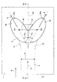
- FIG. 1 is a plan view showing a part of a wall surface exposed to a high-temperature gas to which a film cooling structure according to an embodiment of the present invention is applied.
- FIG. 2 is an enlarged plan view showing a wall surface in which each pair of ejection holes is formed.
- FIG. 3 is a perspective view showing a schematic configuration of the cooling structure of FIG.
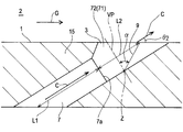
- FIG. 4 is a cross-sectional view taken along line IV-IV in FIG.
- FIG. 5 is a plan view showing the operation of the distributing unit provided in the cooling structure of FIG.
- FIG. 6 is a diagram illustrating the flow of the cooling medium formed on the outer surface of the wall surface.
- FIG. 7 is an isoline diagram of the film efficiency obtained on the wall surface.
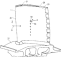
- FIG. 8 is a perspective view of a turbine rotor blade showing an embodiment of the present invention.
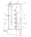
- FIG. 9 is a longitudinal sectional view of the turbine rotor blade.
- FIG. 10 is a cross-sectional view taken along line X
- FIG. 1 is a plan view of a wall surface 1 to which a double jet film cooling structure according to an embodiment of the present invention is applied.
- the wall surface 1 is exposed to the hot gas G flowing in the direction of the arrow.
- a plurality of ejection openings 3 for ejecting a cooling medium such as air into the passage 2 for the hot gas G are arranged in this wall surface 1 in a direction substantially perpendicular to the flow direction of the hot gas G (vertical direction in FIG. 1). ing.
- the upstream side along the flow direction of the hot gas G is referred to as the front side
- the downstream side is referred to as the rear side.
- Each ejection opening 3 includes a pair of first and second ejection holes 5a and 5b arranged side by side in the vertical direction.
- Each of these pairs of ejection holes 5a and 5b is a circular hole opened from an oblique direction with respect to the wall surface 1 by a drill or the like, and opens on the wall surface 1 in an elliptical shape described in detail later.
- each pair of the ejection holes 5 a and 5 b has the ejection directions A and B of the cooling medium C ejected from the ejection holes 5 a and 5 b on the surface along the wall surface 1. That is, they are formed so as to be directed in different directions in a plan view seen from a direction orthogonal to the wall surface 1. As a result, both the cooling media C and C are ejected in directions away from each other.
- a single supply passage 7 for supplying the cooling medium C to each pair of the ejection holes 5a and 5b is formed.
- the supply passage 7 has a circular cross section, and extends obliquely forward (upstream) from the ejection opening 3 in the wall of the wall surface 1.
- Two branch passages 71 and 72 having a circular cross section are branched from the rear end of the supply passage 7, and openings on the wall surface 1 of the branch passages 71 and 72 are ejection holes 5 a and 5 b.
- Each pair of ejection holes 5a and 5b is formed symmetrically with respect to an imaginary plane IP that passes through the middle of both ejection holes 5a and 5b, is parallel to the traveling direction of the hot gas G, and is orthogonal to the wall surface 1.
- FIG. 3 which is a perspective view
- a distribution portion 9 is provided between the pair of ejection holes 5a and 5b in front of the rear ends 5aa and 5bb of the ejection holes 5a and 5b.
- the supply passage 7 is a straight passage
- the passage center line is located on the virtual plane IP.
- the sorting unit 9 is located in the traveling direction of the cooling medium C supplied from the supply passage 7 and is one of the cooling media C. It is formed as a flat wall surface without bending where the parts collide.
- the distribution unit 9 is inclined at an inclination angle ⁇ backward with respect to a virtual orthogonal plane VP orthogonal to the entry direction of the cooling medium C from the supply passage 7 around the axis Z orthogonal to the entry direction. is doing.
- the cooling medium C ejected from each pair of ejection holes 5a and 5b shown in FIGS. 2 to 4 affects each other and acts to press the other side against the wall 1. This will be described with reference to FIGS.
- the cooling medium C that has passed through the supply passage 7 has components C ⁇ b> 1 and C ⁇ b> 2 that flow in regions close to both edges in a plan view seen from the direction orthogonal to the wall surface 1, by the distribution unit 9.
- the refrigerant flows into the separated ejection holes 5a and 5b, and is ejected into the hot gas passage 2 as the straight refrigerant flows F1 and F2 directed in the direction in which the ejection holes 5a and 5b extend.
- the component C3 flowing through the central portion of the cooling medium C that has passed through the supply passage 7 collides with the distribution unit 9.
- Most of the central component C3 that has collided with the distributing unit 9 is directly flow direction of the central component C3, that is, the flow of the high temperature gas G, along the distributing unit 9 formed as a flat surface inclined backward as described above.
- the separated flow F3 along the direction flows out from the sorting unit 9.
- This separated flow F3 enters between the straight refrigerant flows F1 and F2 and has an action of separating the straight refrigerant flows F1 and F2.
- a part of the central component C3 becomes mixed flows F4 and F5 toward both the ejection holes 5a and 5b, and is mixed into the straight refrigerant flow F1 and F2.
- FIG. 6 shows a cross section of the hot gas passage 2 perpendicular to the flow direction of the hot gas G.
- the two ejection holes 5a and 5b are separated from each other by an appropriate distance in order to form the vortex S1 and S2 by effectively generating the low-pressure part 11 and exert the action of pressing the cooling medium C against the wall surface 1. Need to be arranged. As shown in FIG. 2, the shape of each pair of ejection holes 5 a and 5 b excluding the distribution portion 9 in the ejection opening 3 facing the wall surface 1 is formed in a substantially elliptical shape with the ejection directions A and B as major axes, respectively. Has been.
- the ejection holes 5a and 5b are preferably arranged so that the distance W between the ellipse centers O1 and O2 of the ejection holes 5a and 5b is 0D to 2D, where D is the diameter of the supply passage 7. More preferably, the distance W is in the range of 0.5D to 1.5D.
- the center-to-center distance W may be 0D (that is, the state where the centers O1 and O2 overlap).
- the ejection opening 3 has a shape in which both ellipses of the ejection holes 5a and 5b partially overlap.
- the center distance W in the present embodiment is set to 1.3D.
- the horizontal jet angle ⁇ 1 formed by the elliptical major axis direction and the flow direction of the hot gas G is preferably in the range of 5 to 85 °, more preferably in the range of 25 to 35 °.
- the horizontal ejection angle ⁇ 1 in the present embodiment is set to about 30 °.
- the longitudinal ejection angle ⁇ 2 formed by the ejection direction of the cooling medium C ejected from each pair of ejection holes 5a and 5b into the hot gas passage 2 and the wall surface 1 is 5 to 85 °. It is preferably in the range, and more preferably in the range of 20 to 40 °.
- the vertical ejection angle ⁇ 2 in this embodiment is set to about 30 °.
- the length L1 of the supply passage 7 in the wall of the wall surface 1, that is, a part of the wall 15 forming the wall surface 1, and the outlet 7a of the supply passage 7 (the boundary between the supply passage 7 and the branch passages 71 and 72).
- the supply passage length L1 is preferably in the range of 0D to 10D, more preferably in the range of 1D to 5D, in relation to the hole diameter D of the supply passage 7.
- the supply passage length L1 being 0D means that the supply passage 7 exists but the length L1 is extremely small.
- the distance L2 between the supply passage and the ejection opening is preferably in the range of 0.5D to 6D, and more preferably in the range of 1D to 4D. Outside these ranges, the straightness of the straight refrigerant flows F1 and F2 becomes insufficient, and the vortex flows S1 and S2 having a desired strength cannot be obtained.
- the supply passage length L1 and the supply passage-jet opening distance L2 are both the length and distance along the axis of the supply passage 7.
- the supply passage length L1 is set to 3D
- the supply passage-jet opening distance L2 is set to 2D. According to experiments, when the supply passage length L1 and the supply passage-jet opening distance L2 are set in this way, the film efficiency is improved by 2 to 3 times compared to the conventional case.
- the inclination angle ⁇ of the distribution unit 9 with respect to the virtual orthogonal plane VP is preferably in the range of 30 to 85 °, and more preferably in the range of 60 to 80 °. In the present embodiment, the inclination angle ⁇ is set to 70 °.
- the distribution unit 9 By forming the distribution unit 9 as a flat surface and setting the inclination angle ⁇ in this way, the amount of the separated flow F3 flowing out from the distribution unit 9 becomes appropriate, and the separation of the straight refrigerant flow F1 and F2 is effective. Made. As a result, a low-pressure portion is reliably formed between the straight refrigerant flows F1 and F2 in FIG. 5, and the vortex flows S1 and S2 press the flow of the cooling medium C against the wall surface 1 more strongly.
- the distribution part 9 may be formed not as a flat surface but as a curved surface slightly recessed backward.
- FIG. 6 shows an isoline diagram of the film efficiency ⁇ f, ad obtained on the wall surface 1 when the ejection holes 5a, 5b shown in FIG. 2 are formed.
- the cooling medium C ejected from each of the ejection holes 5a and 5b has a region with a film efficiency of 1.0 in the downstream region and a region with a film efficiency of 0.8 around it. Further, an area having a film efficiency of 0.6 is formed around the area.
- Example 8 to 10 show an embodiment in which the present invention is applied to a turbine blade of a gas turbine.
- the gas turbine includes a compressor that compresses air, a combustor that supplies and burns fuel to the compressed air from the compressor, and a turbine that is driven by high-temperature and high-pressure combustion gas from the combustor.
- the turbine has a large number of blades 23 implanted on the outer periphery of a turbine disk 21 shown in FIG.
- Six pairs of ejection holes 5a and 5b are arranged in the radial direction in a portion slightly rearward from the front edge 25 on the blade surface (wall surface 1) of the moving blade 23 shown in FIG. 8, and these ejection holes 5a and 5b are arranged. However, it faces the hot gas (combustion gas) passage 2 between the adjacent rotor blades 23.
- a folded cooling medium passage 27 shown in FIG. 9 is formed inside the rotor blade 23, and the ejection holes 5 a and 5 b communicate with the middle portion of the cooling medium passage 27.
- a cooling medium C made of air extracted from the compressor is introduced from the passage in the turbine disk 21 into the cooling medium passage 27, injected from the injection holes 5 a and 5 b, and then the ejection hole 31 opened at the blade tip 29. Is ejected into the passage 2.
- a film flow CF of the cooling medium C is formed on the blade surface 1 by the cooling medium C injected from the ejection holes 5a and 5b opened on the blade surface which is the wall surface 1 shown in FIG. Effectively cooled.
- a plurality of pairs of ejection holes 5a and 5b are arranged at equal intervals in a vertical direction.
- the number and arrangement of the plurality of pairs of ejection holes 5a and 5b may be appropriately selected.
- a plurality of pairs of ejection holes 5a, 5b arranged in a radial direction at equal intervals are provided in two rows apart in the front-rear direction, and the radial position of each pair of ejection holes 5a, 5b in the front row, The radial positions of the pairs of ejection holes 5a and 5b in the rear row may be shifted from each other.
- the present invention can be widely applied to wall surfaces facing a passage of high-temperature gas, such as a stationary blade and an inner cylinder of a combustor, in addition to a moving blade of a gas turbine.
- the present invention provides an injection hole in a wall faced to a passage of high-temperature gas such as a moving blade, a stationary blade, and an inner cylinder of a combustor in a gas turbine engine, and a cooling medium injected from the injection hole along the wall surface.
- high-temperature gas such as a moving blade, a stationary blade, and an inner cylinder of a combustor in a gas turbine engine
- a cooling medium injected from the injection hole along the wall surface.
- the present invention can be widely applied to wall surfaces that face the passage of high-temperature gas, such as a stationary blade and an inner cylinder of a combustor, in addition to a moving blade of a gas turbine.
Landscapes
- Engineering & Computer Science (AREA)
- Mechanical Engineering (AREA)
- General Engineering & Computer Science (AREA)
- Chemical & Material Sciences (AREA)
- Combustion & Propulsion (AREA)
- Physics & Mathematics (AREA)
- Thermal Sciences (AREA)
- Turbine Rotor Nozzle Sealing (AREA)
Abstract
冷却媒体フィルムが壁面から剥離することを抑制することにより、壁面上におけるフィルム効率を高めて、壁面を効率的に冷却できるフィルム冷却構造を提供する。高温ガス(G)の通路(2)に臨む壁面(1)に、冷却媒体(C)を前記通路(2)に噴出する1対以上の噴出孔(5a,5b)が設けられ、前記各対の噴出孔(5a,5b)に前記冷却媒体(C)を供給する単一の供給通路(7)が壁内に形成され、前記各対の噴出孔(5a,5b)の間に、これら噴出孔の後端(5aa,5ba)よりも前方に位置し、前記供給通路(7)からの冷却媒体(C)を各対の噴出孔に振り分ける振り分け部(9)が形成され、各対の噴出孔からの冷却媒体が、これら冷却媒体を互いに前記壁面に押しつける方向の渦流(S1,S2)を形成するように、前記冷却媒体(C)の噴出方向が、前記高温ガス(G)の流れ方向に対して傾斜して設定されている。
Description
本発明は、ガスタービンエンジンにおける動翼、静翼、燃焼器の内筒などのように高温ガスの通路に臨む壁面に噴出孔を設け、この噴出孔から噴出される冷却媒体を壁面に沿って流すことによって壁面の冷却を行うフィルム冷却構造に関する。
従来、ガスタービンエンジン(以下、単に「ガスタービン」という。)における動翼のような壁面には、同一方向を指向する多数の噴出孔が設けられ、これら噴出孔から噴出される空気のような冷却媒体のフィルム流により、高温ガスに曝される前記壁面を冷却する。このようなフィルム冷却構造として、例えば、冷却媒体の壁面への噴出口の中央部に、前記噴出孔の後端位置に底辺がある平面視でほぼ二等辺三角形状をなし、かつその頂点部分が上流側(前側)に位置するリブを設け、このリブにより冷却媒体を左右方向に分散させて、壁面の均一な冷却を図ることが提案されている(特許文献1)。
上記の冷却構造では、リブが噴出孔の後端まで延び、かつ冷却媒体の流れ方向に沿って延びるリブの両側面に、壁面の内方から壁面にかけて両冷却媒体流の中央方向に向かって傾斜する傾斜面が形成されているので、リブによる冷却媒体流の分離が十分でない。つまり、冷却媒体はリブによって分離されて左右一対の流れとなるが、その際にリブの傾斜した両側面に沿って、一部の冷却媒体がリブの前端から後端まで、すなわち、噴出孔の後端までの広い領域にわたって一対の冷却媒体流間の中央軸方向に向かってガイドされる。これにより、一部の冷却媒体が噴出孔の後端から前記中央方向へ向かって斜め後方へ噴出されるので、両冷却媒体流の分離が十分になされなくなる。この場合、両冷却媒体流間の低圧部に前記一部の冷却媒体が流れ込む結果、低圧部の圧力が上昇し、冷却媒体流が壁面から剥離し易くなるために、壁面上における冷却効率を示すフィルム効率が低くなる。ここで、フィルム効率とは、ηf,ad=(Tg―Tf)/(Tg―Tc)で表される指標である。この式において、Tgはガスの温度、Tfは壁面の表面温度、Tcは壁面上における冷却媒体の温度である。
そこで、本発明は、冷却媒体フィルムが壁面から剥離することを抑制することにより、ガスタービンの動,静翼などの壁面上におけるフィルム効率を高めて、壁面を効率的に冷却することができるフィルム冷却構造を提供することを目的とする。
上記目的を達成するために、本発明に係るダブルジェット式フィルム冷却構造は、高温ガスの通路に臨む壁面に、冷却媒体を前記通路に噴出する1対以上の噴出孔が設けられ、前記各対の噴出孔に前記冷却媒体を供給する単一の供給通路が壁内に形成され、前記各対の噴出孔の間に、これら噴出孔の後端よりも前方に位置し、前記供給通路からの冷却媒体を各対の噴出孔に振り分ける振り分け部が形成され、各対の噴出孔からの冷却媒体が、これら冷却媒体を互いに前記壁面に押しつける方向の渦流を形成するように、前記冷却媒体の噴出方向が、前記高温ガスの流れ方向に対して傾斜して設定されている。
この構成によれば、単一の供給通路を通った冷却媒体が、振り分け部により、1対の噴出孔に向かうように振り分けられる。このとき、振り分け部は噴出孔の後端よりも前方に位置しているから、振り分けられた後の冷却媒体が噴出孔の後部により規制されて、指向性の高い1対の直進流を形成する。この指向性の高い1対の直進流の間には、十分圧力の低い低圧部が生じるので、直進流が形成する渦流により、直進流の周りからこの低圧部に巻き込まれて壁面に向かう強い流れが形成される。このため、冷却媒体が壁面から剥離することが抑制され、壁面上におけるフィルム効率が高められて、壁面が効果的に冷却される。
前記振り分け部は、この振り分け部に衝突する冷却媒体の進入方向と直交する仮想直交面に対し、前記進入方向と直交する軸心回りに後方へ傾斜していることが好ましい。この構成によれば、振り分け部に衝突する冷却媒体が、各噴出孔の方向に均等に振り分けられる。その際、振り分け部には傾斜した側面が存在しないので、振り分けられた1対の冷却媒体の一部が冷却媒体の進行方向に沿った中央部に流出することが抑制されて、両冷却媒体の分離が十分になされる。その結果、冷媒の前記直進流間に確実に低圧部が形成され、渦流が冷却媒体の流れを強力に壁面に押し付ける。
前記1対の噴出孔からの前記冷却媒体の各噴出方向の、前記高温ガスの流れ方向に対する前記壁面上に沿った水平方向噴出角度が、前記流れ方向を挟んで互いに反対方向を向くθ1に設定されていることが好ましい。これにより、高温ガスの流れ方向に沿って、壁面上に冷却媒体のフィルム流が効果的に形成されて、フィルム効率が一層向上する。
前記水平方向噴出角度θ1は5~85°の範囲にあることが好ましく、他方、前記各噴出孔から前記高温ガス通路へ噴出される前記冷却媒体の噴出方向と前記壁面とがなす縦方向噴出角度θ2は5~85°の範囲にあることが好ましい。また、前記1対の噴出孔の、前記壁面に臨む開口における、前記振り分け部を除いた形状が、それぞれ、前記噴出方向を長軸とするほぼ楕円形状であり、これら2つの楕円形状の中心間隔が、前記供給通路の孔径Dに対して0~2Dに設定されていることが好ましい。さらに、前記供給通路の長さL1が、前記供給通路の孔径Dに対して0~10Dに設定されていることが好ましく、また、前記供給通路の出口から前記1対の噴出孔の前記壁面に臨む開口までの距離L2が、前記供給通路の孔径Dに対して0.5~6Dに設定されていることが好ましい。これら好ましい構成によれば、壁面に向かう強い渦が生成されて、壁面をより効果的に冷却できる。
本発明によれば、高温ガスに曝される壁面上における冷却媒体の剥離を抑制して壁面上に良好なフィルム流を生成することができ、これにより壁面の冷却を効率的に行うことができる。
以下,本発明の好ましい実施形態を図面に基づいて説明する。
図1は本発明の一実施形態であるダブルジェット式フィルム冷却構造を適用した壁面1の平面図である。壁面1は矢印方向に流れる高温ガスGに曝されている。この壁面1には、高温ガスGの通路2に空気のような冷却媒体を噴出する噴出開口3が、高温ガスGの流れ方向にほぼ直交する方向(図1の上下方向)に複数並べて配置されている。なお、以下の説明において、高温ガスGの流れ方向に沿った上流側を前側と呼び、下流側を後側と呼ぶ。
各噴出開口3は、上下方向に並べて配置された1対をなす第1および第2噴出孔5a,5bを含んでいる。これら各対の噴出孔5a,5bは、ドリルなどにより壁面1に対して斜め方向から開孔された円孔であり、壁面1上では、後に詳述する楕円形状に開口している。各対の噴出孔5a,5bは、図2の拡大正面図に示すように、噴出孔5a,5bから噴出される冷却媒体Cの噴出方向A,Bが、壁面1に沿った面上で、つまり壁面1と直交する方向から見た平面視で、互いに異なる方向を指向するように形成されている。その結果、両冷却媒体C,Cは互いに離間する方向に噴出される。
壁面1の壁内には、各対の両噴出孔5a,5bに冷却媒体Cを供給する単一の供給通路7が形成されている。供給通路7は、円形の横断面を有し、壁面1の壁内で、噴出開口3から前方(上流側)に傾斜して延びている。供給通路7の後端から、横断面円形の2つの分岐通路71,72が分岐しており、分岐通路71,72の壁面1上の開口が噴出孔5a,5bとなっている。各対の噴出孔5a,5bは、両噴出孔5a,5bの中間を通り、高温ガスGの進行方向に平行でかつ壁面1に直交する仮想平面IPに対して対称に形成されている。
斜視図である図3に明示するように、各対の噴出孔5a,5bの間には、これら噴出孔5a,5bの後端5aa,5bbよりも前方に、振り分け部9が設けられている。図2に示すように、供給通路7は直線通路であり、その通路中心線が前記仮想平面IP上に位置している。図2のIV-IV線に沿った断面図である図4に示すように、振り分け部9は、供給通路7から供給される冷却媒体Cの進行方向上に位置して、冷却媒体Cの一部が衝突する曲がりのない平坦な壁面として形成されている。より具体的には、振り分け部9は、供給通路7からの冷却媒体Cの進入方向と直交する仮想直交面VPに対し、進入方向と直交する軸心Z回りに後方へ、傾斜角度αで傾斜している。
図2~4に示した各対の噴出孔5a,5bから噴出される冷却媒体Cは、相互に影響し合い、相手方を壁面1に押し付けるように作用する。その様子を、図5,6を参照しながら説明する。図4に示すように、供給通路7を通過した冷却媒体Cは、壁面1と直交する方向から見た平面視で、両縁部寄りとなる領域を流れる成分C1,C2が、振り分け部9によって分離された各噴出孔5a,5bに流入し、各噴出孔5a,5bが延在する方向を指向する直進的な冷媒流F1,F2として高温ガス通路2に噴出される。特に、噴出孔5a,5bの後端5aa,5baが振り分け部9よりも後方に位置しているので、噴出孔5a,5bの振り分け部9よりも後方に位置する部分から噴出される直進冷媒流F1,F2は、指向性の高い流れとして形成される。
一方、供給通路7を通過した冷却媒体Cのうちの、中央部を流れる成分C3は、振り分け部9に衝突する。振り分け部9に衝突した中央成分C3の大部分は、上述のように後方に傾斜した平坦面として形成されている振り分け部9に沿って、そのまま中央成分C3の流れ方向、つまり高温ガスGの流れ方向に沿った分離流F3となって振り分け部9から流出する。この分離流F3は、直進冷媒流F1,F2の間に入って、直進冷媒流F1,F2を分離する作用を持つ。中央成分C3の一部は両噴出孔5a,5bに向かう混入流F4,F5となり、直進冷媒流F1,F2に混入される。
高温ガス通路2の、高温ガスGの流れ方向と直交する横断面を図6に示す。振り分け部9からの分離流F3により、指向性の高い直進冷媒流F1とF2とが壁面1に平行な方向に分離される結果、直進冷媒流F1,F2間に強い低圧部11が発生する。これにより、各直進冷媒流F1,F2の内側部、つまり互いに対向する部分に、壁面1へ向かう流れが生じる。その結果、直進冷媒流F1,F2に、内側で壁面1へ向かって冷却媒体Cを巻き込むような互いに逆方向の渦流S1,S2が発生する。これらの渦流S1,S2は、それぞれ、直進冷媒流F1,F2を壁面1に押し付けるように作用する。
低圧部11を効果的に発生させることにより渦流S1,S2を形成して、冷却媒体Cを壁面1に押し付ける作用を発揮するために、2つの噴出孔5a,5bは互いに適切な距離だけ離間して配設される必要がある。図2に示すように、壁面1に臨む噴出開口3における振り分け部9を除いた各対の噴出孔5a,5bの形状は、それぞれ、噴出方向A,Bを長軸とするほぼ楕円状に形成されている。噴出孔5aと5bとは、供給通路7の孔径をDとして、噴出孔5a,5bの両楕円の中心O1,O2間の距離Wが0D~2Dとなるように配置されることが好ましく、中心間距離Wが0.5D~1.5Dの範囲にあることがより好ましい。なお、中心間距離Wは0D(つまり、中心O1,O2が重なっている状態)であっても構わない。このとき、噴出開口3は噴出孔5a,5bの両楕円が一部重複する形状となる。本実施形態における中心間距離Wは、1.3Dに設定されている。
また、各対の噴出孔5a,5bから高温ガス通路2へ噴出される冷却媒体Cの噴出方向の壁面1に平行な成分、すなわち、壁面1と直交する方向から見て、噴出孔5a,5bの楕円形状の長軸方向と、高温ガスGの流れ方向とがなす水平方向噴出角度θ1は、5~85°の範囲にあることが好ましく、25~35°の範囲にあることがより好ましい。本実施形態における水平方向噴出角度θ1は、約30°に設定されている。他方、図3に示すように、各対の噴出孔5a,5bから高温ガス通路2へ噴出される冷却媒体Cの噴出方向と壁面1とがなす縦方向噴出角度θ2は、5~85°の範囲にあることが好ましく、20~40°の範囲にあることがより好ましい。本実施形態における縦方向噴出角度θ2は、約30°に設定されている。
さらに、壁面1の壁内、つまり壁面1を形成する壁15の一部における供給通路7の長さL1と、供給通路7の出口7a(供給通路7と分岐通路71,72との境界)から噴出開口3までの距離L2の比は、L1:L2=3~5:2~4の範囲にあることが好ましく、3.5~4.5:2.5~3.5の範囲にあることが特に好ましい。本実施形態においては、L1:L2=3:2に設定されている。また、供給通路長さL1は、供給通路7の孔径Dとの関係において、0D~10Dの範囲にあることが好ましく、1D~5Dの範囲にあることがより好ましい。ここで、供給通路長さL1が0Dであるとは、供給通路7は存在するがその長さL1が極めて微小であることを意味する。一方、供給通路-噴出開口間距離L2は、0.5D~6Dの範囲にあることが好ましく、1D~4Dの範囲にあることがより好ましい。これらの範囲を外れると、直進冷媒流F1,F2の直進性が不十分となり、所望の強さの渦流S1,S2が得られない。なお、供給通路長さL1および供給通路-噴出開口間距離L2は、いずれも、供給通路7の軸心に沿った長さおよび距離である。本実施形態では、供給通路長さL1を3D、供給通路-噴出開口間距離L2を2Dに設定している。実験によれば、供給通路長さL1、供給通路-噴出開口間距離L2をこのように設定した場合、フィルム効率が従来に比べて2倍~3倍に向上した。
さらに、仮想直交面VPに対する振り分け部9の傾斜角度αは、30~85°の範囲にあることが好ましく、60~80°の範囲にあることがより好ましい。本実施形態において、傾斜角度αは70°に設定されている。振り分け部9を平坦面として形成し、かつ、傾斜角度αをこのように設定することにより、振り分け部9から流出する分離流F3の量が適切となり、直進冷媒流F1とF2との分離が効果的になされる。その結果、図5の直進冷媒流F1,F2間に、確実に低圧部が形成され、渦流S1,S2が一層強力に冷却媒体Cの流れを壁面1に押し付ける。ただし、振り分け部9は平坦面でなく、若干後方へ凹入した湾曲面として形成してもよい。
以上の冷却構造によれば、図6に示すように、各対の噴出孔5a,5bからの冷却媒体Cが、低圧部11に巻き込まれた渦流S1,S2によって壁面1に押し付けられて、壁面1の広い範囲に接触し、冷却媒体Cのフィルム流が形成される。このようにして冷却媒体Cが壁面1から剥離することが抑制され、壁面1上におけるフィルム効率が高められて、壁面1が効果的に冷却される。図7は、図2に示す噴出孔5a,5bを形成した場合に、壁面1上に得られるフィルム効率ηf,adの等値線図を示している。同図から明らかなように、各噴出孔5a,5bから噴出される冷却媒体Cは、その下流域に、フィルム効率1.0の領域を、その周りにはフィルム効率0.8の領域を、さらに、その周りにはフィルム効率0.6の領域を、それぞれ広域にわたって形成している。このような極めて高いフィルム効率を有する冷却媒体Cのフィルム流を壁面1に形成することにより、冷却媒体Cの壁面1からの剥離が阻止されて壁面1の効率的な冷却が行われる。
[実施例]
図8ないし図10は、本発明をガスタービンのタービン翼に適用した実施例を示す。ガスタービンは、空気を圧縮する圧縮機、圧縮機からの圧縮空気に燃料を供給して燃焼させる燃焼器、燃焼器からの高温、高圧の燃焼ガスにより駆動されるタービンとを備えている。前記タービンは、図9に示すタービンディスク21の外周に多数の動翼23を植設したものである。図8に示す動翼23の翼面(壁面1)における前縁25から若干後方寄りの部分に、6対の噴出孔5a,5bが径方向に並べて配置されており、これら噴出孔5a,5bが、隣接する動翼23間の高温ガス(燃焼ガス)通路2に臨んでいる。
図8ないし図10は、本発明をガスタービンのタービン翼に適用した実施例を示す。ガスタービンは、空気を圧縮する圧縮機、圧縮機からの圧縮空気に燃料を供給して燃焼させる燃焼器、燃焼器からの高温、高圧の燃焼ガスにより駆動されるタービンとを備えている。前記タービンは、図9に示すタービンディスク21の外周に多数の動翼23を植設したものである。図8に示す動翼23の翼面(壁面1)における前縁25から若干後方寄りの部分に、6対の噴出孔5a,5bが径方向に並べて配置されており、これら噴出孔5a,5bが、隣接する動翼23間の高温ガス(燃焼ガス)通路2に臨んでいる。
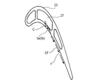
動翼23の内部には、図9に示す折り返した冷却媒体通路27が形成されており、この冷却媒体通路27の中途部に噴出孔5a,5bが連通している。圧縮機から抽気された空気からなる冷却媒体Cが、タービンディスク21内の通路から冷却媒体通路27に導入され、噴出孔5a,5bから噴射されたのち、翼端29に開口させた噴出孔31から通路2内に噴出される。こうして、図10に示す壁面1である翼面に開口した噴出孔5a,5bから噴射される冷却媒体Cにより、翼面1上に冷却媒体Cのフィルム流CFが形成されて、動翼23が効果的に冷却される。
上記実施例では、複数対の噴出孔5a,5bを、上下方向1列に等間隔に並べて配置した例について説明したが、複数対の噴出孔5a,5bの数および配置は適宜選択してよい。例えば、複数対の噴出孔5a,5bを径方向に等間隔に並べた列を、前後方向に離して2列設けて、前側の列の各対の噴出孔5a,5bの径方向位置と、後側の列の各対の噴出孔5a,5bの径方向位置とをずらして配置してもよい。
本発明は、ガスタービンの動翼のほかに、静翼、燃焼器の内筒などのように、高温ガスの通路に臨む壁面に対して広く適用できる。
以上のとおり、図面を参照しながら本発明の好適な実施形態を説明したが、本発明の趣旨を逸脱しない範囲内で、種々の追加、変更または削除が可能である。したがって、そのようなものも本発明の範囲内に含まれる。
本発明は、ガスタービンエンジンにおける動翼、静翼、燃焼器の内筒などのように高温ガスの通路に臨む壁面に噴出孔を設け、この噴出孔から噴出される冷却媒体を壁面に沿って流すことによって壁面の冷却を行うフィルム冷却構造において、冷却媒体が壁面から剥離することを抑制し、壁面を効果的に冷却するために有用である。さらに、本発明は、ガスタービンの動翼のほかに、静翼、燃焼器の内筒などのように、高温ガスの通路に臨む壁面に対して広く適用することができる。
1 壁面
2 高温ガス通路
5a,5b 1対の噴出孔
7 供給通路
9 振り分け部
A,B 冷却媒体の噴出方向
S1,S2 渦流
C 冷却媒体
D 供給通路の孔径
G 高温ガス
θ1 水平方向噴出角度
θ2 縦方向噴出角度
2 高温ガス通路
5a,5b 1対の噴出孔
7 供給通路
9 振り分け部
A,B 冷却媒体の噴出方向
S1,S2 渦流
C 冷却媒体
D 供給通路の孔径
G 高温ガス
θ1 水平方向噴出角度
θ2 縦方向噴出角度
Claims (8)
- 高温ガスの通路に臨む壁面に、冷却媒体を前記通路に噴出する1対以上の噴出孔が設けられ、
前記各対の噴出孔に前記冷却媒体を供給する単一の供給通路が壁内に形成され、
前記各対の噴出孔の間に、これら噴出孔の後端よりも前方に位置し、前記供給通路からの冷却媒体を各対の噴出孔に振り分ける振り分け部が形成され、
各対の噴出孔からの冷却媒体が、これら冷却媒体を互いに前記壁面に押しつける方向の渦流を形成するように、前記冷却媒体の噴出方向が、前記高温ガスの流れ方向に対して傾斜して設定されている、ダブルジェット式フィルム冷却構造。 - 請求項1において、前記振り分け部は、この振り分け部に衝突する冷却媒体の進入方向と直交する仮想直交面に対し、前記進入方向と直交する軸心回りに後方へ傾斜しているダブルジェット式フィルム冷却構造。
- 請求項1または2において、前記1対の噴出孔からの前記冷却媒体の各噴出方向の、前記高温ガスの流れ方向に対する前記壁面に沿った水平方向噴出角度が、前記流れ方向を挟んで互いに反対方向を向くθ1に設定されているダブルジェット式フィルム冷却構造。
- 請求項1から3のいずれか一項において、前記水平方向噴出角度θ1が5~85°の範囲にあるダブルジェット式フィルム冷却構造。
- 請求項1から4のいずれか一項において、前記各噴出孔から前記高温ガス通路へ噴出される前記冷却媒体の噴出方向と前記壁面とがなす縦方向噴出角度θ2が5~85°の範囲にあるダブルジェット式フィルム冷却構造。
- 請求項1から5のいずれか一項において、前記1対の噴出孔の、前記壁面に臨む開口における、前記振り分け部を除いた形状が、それぞれ、前記噴出方向を長軸とするほぼ楕円形状であり、これら2つの楕円形状の中心間隔が、前記供給通路の孔径Dに対して0~2Dに設定されているダブルジェット式フィルム冷却構造。
- 請求項1から6のいずれか一項において、前記供給通路の長さL1が、前記供給通路の孔径Dに対して0~10Dに設定されているダブルジェット式フィルム冷却構造。
- 請求項1から7のいずれか一項において、前記供給通路の出口から前記1対の噴出孔の前記壁面に臨む開口までの距離L2が、前記供給通路の孔径Dに対して0.5~6Dに設定されているダブルジェット式フィルム冷却構造。
Priority Applications (2)
| Application Number | Priority Date | Filing Date | Title |
|---|---|---|---|
| EP11758943.2A EP2554792B1 (en) | 2010-03-24 | 2011-03-02 | Double-jet film cooling structure |
| US13/636,667 US9599411B2 (en) | 2010-03-24 | 2011-03-02 | Double-jet type film cooling structure |
Applications Claiming Priority (2)
| Application Number | Priority Date | Filing Date | Title |
|---|---|---|---|
| JP2010067329A JP4954309B2 (ja) | 2010-03-24 | 2010-03-24 | ダブルジェット式フィルム冷却構造 |
| JP2010-067329 | 2010-03-24 |
Publications (1)
| Publication Number | Publication Date |
|---|---|
| WO2011118131A1 true WO2011118131A1 (ja) | 2011-09-29 |
Family
ID=44672712
Family Applications (1)
| Application Number | Title | Priority Date | Filing Date |
|---|---|---|---|
| PCT/JP2011/001207 Ceased WO2011118131A1 (ja) | 2010-03-24 | 2011-03-02 | ダブルジェット式フィルム冷却構造 |
Country Status (4)
| Country | Link |
|---|---|
| US (1) | US9599411B2 (ja) |
| EP (1) | EP2554792B1 (ja) |
| JP (1) | JP4954309B2 (ja) |
| WO (1) | WO2011118131A1 (ja) |
Cited By (7)
| Publication number | Priority date | Publication date | Assignee | Title |
|---|---|---|---|---|
| CN103244196A (zh) * | 2012-02-08 | 2013-08-14 | 中国科学院工程热物理研究所 | 一种离散气膜冷却孔型 |
| WO2013165502A2 (en) | 2012-02-15 | 2013-11-07 | United Technologies Corporation | Cooling hole with thermo-mechanical fatigue resistance |
| JP2014148938A (ja) * | 2013-02-01 | 2014-08-21 | Siemens Ag | ターボ機械のためのフィルム冷却されるタービンブレード |
| US20140271229A1 (en) * | 2011-12-15 | 2014-09-18 | Ihi Corporation | Turbine blade |
| EP2861909A2 (en) * | 2012-06-13 | 2015-04-22 | General Electric Company | Gas turbine engine wall |
| EP2815100A4 (en) * | 2012-02-15 | 2015-12-30 | United Technologies Corp | GAS TURBINE COMPONENT WITH COMPOUND THRESHOLD COOLING CONFIGURATION |
| CN112282857A (zh) * | 2020-10-26 | 2021-01-29 | 上海交通大学 | 一种气膜冷却孔型结构 |
Families Citing this family (37)
| Publication number | Priority date | Publication date | Assignee | Title |
|---|---|---|---|---|
| US9696035B2 (en) | 2010-10-29 | 2017-07-04 | General Electric Company | Method of forming a cooling hole by laser drilling |
| JP2013100771A (ja) * | 2011-11-08 | 2013-05-23 | Central Research Institute Of Electric Power Industry | 高温部品のフィルム冷却構造 |
| JP5923936B2 (ja) | 2011-11-09 | 2016-05-25 | 株式会社Ihi | フィルム冷却構造及びタービン翼 |
| JP5982807B2 (ja) * | 2011-12-15 | 2016-08-31 | 株式会社Ihi | タービン翼 |
| US9416971B2 (en) * | 2012-02-15 | 2016-08-16 | United Technologies Corporation | Multiple diffusing cooling hole |
| US9309771B2 (en) * | 2012-10-25 | 2016-04-12 | United Technologies Corporation | Film cooling channel array with multiple metering portions |
| JP6134193B2 (ja) * | 2013-04-23 | 2017-05-24 | 三菱日立パワーシステムズ株式会社 | フィルム冷却構造 |
| CA2849183C (en) * | 2013-05-01 | 2016-12-06 | General Electric Company | Substrate with shaped cooling holes and methods of manufacture |
| JP5567180B1 (ja) * | 2013-05-20 | 2014-08-06 | 川崎重工業株式会社 | タービン翼の冷却構造 |
| JP5530001B1 (ja) | 2013-05-22 | 2014-06-25 | 川崎重工業株式会社 | ダブルジェット式フイルム冷却構造とその製造方法 |
| CN103437889B (zh) * | 2013-08-06 | 2016-03-30 | 清华大学 | 一种用于燃气涡轮发动机冷却的分支气膜孔结构 |
| US9708915B2 (en) | 2014-01-30 | 2017-07-18 | General Electric Company | Hot gas components with compound angled cooling features and methods of manufacture |
| US20160090843A1 (en) * | 2014-09-30 | 2016-03-31 | General Electric Company | Turbine components with stepped apertures |
| US20160245094A1 (en) * | 2015-02-24 | 2016-08-25 | General Electric Company | Engine component |
| US11313235B2 (en) * | 2015-03-17 | 2022-04-26 | General Electric Company | Engine component with film hole |
| US10030525B2 (en) * | 2015-03-18 | 2018-07-24 | General Electric Company | Turbine engine component with diffuser holes |
| US10208602B2 (en) * | 2015-04-27 | 2019-02-19 | United Technologies Corporation | Asymmetric diffuser opening for film cooling holes |
| CN104879171B (zh) * | 2015-05-08 | 2016-11-02 | 西北工业大学 | 一种用于涡轮叶片的y型气膜孔结构 |
| KR101857786B1 (ko) * | 2015-05-27 | 2018-05-15 | 두산중공업 주식회사 | 개선된 연료 분출구가 구비된 프리믹서를 포함하는 연료공급노즐. |
| DE102015210385A1 (de) * | 2015-06-05 | 2016-12-08 | Rolls-Royce Deutschland Ltd & Co Kg | Vorrichtung zur Kühlung einer Wandung eines Bauteils einer Gasturbine |
| CA2933884A1 (en) * | 2015-06-30 | 2016-12-30 | Rolls-Royce Corporation | Combustor tile |
| US10392947B2 (en) | 2015-07-13 | 2019-08-27 | General Electric Company | Compositions and methods of attachment of thick environmental barrier coatings on CMC components |
| US10197278B2 (en) | 2015-09-02 | 2019-02-05 | General Electric Company | Combustor assembly for a turbine engine |
| US11149646B2 (en) | 2015-09-02 | 2021-10-19 | General Electric Company | Piston ring assembly for a turbine engine |
| US10168051B2 (en) | 2015-09-02 | 2019-01-01 | General Electric Company | Combustor assembly for a turbine engine |
| US9976746B2 (en) | 2015-09-02 | 2018-05-22 | General Electric Company | Combustor assembly for a turbine engine |
| US10563867B2 (en) | 2015-09-30 | 2020-02-18 | General Electric Company | CMC articles having small complex features for advanced film cooling |
| CN105298649B (zh) * | 2015-11-20 | 2017-10-03 | 清华大学 | 一种用于燃气涡轮发动机薄壁热端部件的气膜冷却孔结构 |
| CN106870014B (zh) * | 2016-12-30 | 2019-09-27 | 哈尔滨工程大学 | 一种依据气膜孔出口速度分布而设计的开槽结构 |
| US10697301B2 (en) * | 2017-04-07 | 2020-06-30 | General Electric Company | Turbine engine airfoil having a cooling circuit |
| EP3450682A1 (en) * | 2017-08-30 | 2019-03-06 | Siemens Aktiengesellschaft | Wall of a hot gas component and corresponding hot gas component |
| US10648342B2 (en) | 2017-12-18 | 2020-05-12 | General Electric Company | Engine component with cooling hole |
| US11402097B2 (en) | 2018-01-03 | 2022-08-02 | General Electric Company | Combustor assembly for a turbine engine |
| JP7168926B2 (ja) * | 2018-03-28 | 2022-11-10 | 三菱重工業株式会社 | フィルム冷却構造 |
| US11359495B2 (en) | 2019-01-07 | 2022-06-14 | Rolls- Royce Corporation | Coverage cooling holes |
| US11959396B2 (en) * | 2021-10-22 | 2024-04-16 | Rtx Corporation | Gas turbine engine article with cooling holes for mitigating recession |
| JP2025056639A (ja) * | 2023-09-27 | 2025-04-08 | 三菱重工航空エンジン株式会社 | 冷却壁部構造及びこれを備えた高温部品並びに冷却壁部構造の製造方法 |
Citations (4)
| Publication number | Priority date | Publication date | Assignee | Title |
|---|---|---|---|---|
| JP2006009785A (ja) * | 2004-06-23 | 2006-01-12 | General Electric Co <Ge> | シェブロンフィルム冷却式壁 |
| WO2007052337A1 (ja) * | 2005-11-01 | 2007-05-10 | Ihi Corporation | タービン部品 |
| JP2008008288A (ja) * | 2006-06-29 | 2008-01-17 | United Technol Corp <Utc> | ガスタービンエンジンならびに部品およびその冷却口の形状を最適化する方法 |
| JP2008248733A (ja) | 2007-03-29 | 2008-10-16 | Mitsubishi Heavy Ind Ltd | ガスタービン用高温部材 |
Family Cites Families (7)
| Publication number | Priority date | Publication date | Assignee | Title |
|---|---|---|---|---|
| US4529358A (en) | 1984-02-15 | 1985-07-16 | The United States Of America As Represented By The Administrator Of The National Aeronautics And Space Administration | Vortex generating flow passage design for increased film cooling effectiveness |
| US5419681A (en) * | 1993-01-25 | 1995-05-30 | General Electric Company | Film cooled wall |
| US6092982A (en) * | 1996-05-28 | 2000-07-25 | Kabushiki Kaisha Toshiba | Cooling system for a main body used in a gas stream |
| JP2810023B2 (ja) * | 1996-09-18 | 1998-10-15 | 株式会社東芝 | 高温部材冷却装置 |
| US6383602B1 (en) * | 1996-12-23 | 2002-05-07 | General Electric Company | Method for improving the cooling effectiveness of a gaseous coolant stream which flows through a substrate, and related articles of manufacture |
| US20110097191A1 (en) * | 2009-10-28 | 2011-04-28 | General Electric Company | Method and structure for cooling airfoil surfaces using asymmetric chevron film holes |
| US8905713B2 (en) * | 2010-05-28 | 2014-12-09 | General Electric Company | Articles which include chevron film cooling holes, and related processes |
-
2010
- 2010-03-24 JP JP2010067329A patent/JP4954309B2/ja active Active
-
2011
- 2011-03-02 EP EP11758943.2A patent/EP2554792B1/en active Active
- 2011-03-02 WO PCT/JP2011/001207 patent/WO2011118131A1/ja not_active Ceased
- 2011-03-02 US US13/636,667 patent/US9599411B2/en active Active
Patent Citations (4)
| Publication number | Priority date | Publication date | Assignee | Title |
|---|---|---|---|---|
| JP2006009785A (ja) * | 2004-06-23 | 2006-01-12 | General Electric Co <Ge> | シェブロンフィルム冷却式壁 |
| WO2007052337A1 (ja) * | 2005-11-01 | 2007-05-10 | Ihi Corporation | タービン部品 |
| JP2008008288A (ja) * | 2006-06-29 | 2008-01-17 | United Technol Corp <Utc> | ガスタービンエンジンならびに部品およびその冷却口の形状を最適化する方法 |
| JP2008248733A (ja) | 2007-03-29 | 2008-10-16 | Mitsubishi Heavy Ind Ltd | ガスタービン用高温部材 |
Non-Patent Citations (1)
| Title |
|---|
| See also references of EP2554792A4 * |
Cited By (14)
| Publication number | Priority date | Publication date | Assignee | Title |
|---|---|---|---|---|
| US9759069B2 (en) * | 2011-12-15 | 2017-09-12 | Ihi Corporation | Turbine blade |
| US20140271229A1 (en) * | 2011-12-15 | 2014-09-18 | Ihi Corporation | Turbine blade |
| CN103244196A (zh) * | 2012-02-08 | 2013-08-14 | 中国科学院工程热物理研究所 | 一种离散气膜冷却孔型 |
| WO2013165502A2 (en) | 2012-02-15 | 2013-11-07 | United Technologies Corporation | Cooling hole with thermo-mechanical fatigue resistance |
| EP2815103A4 (en) * | 2012-02-15 | 2016-01-06 | United Technologies Corp | COOLING HOLE WITH RESISTANCE TO THERMOMECHANICAL FATIGUE |
| EP2815100A4 (en) * | 2012-02-15 | 2015-12-30 | United Technologies Corp | GAS TURBINE COMPONENT WITH COMPOUND THRESHOLD COOLING CONFIGURATION |
| US9869186B2 (en) | 2012-02-15 | 2018-01-16 | United Technologies Corporation | Gas turbine engine component with compound cusp cooling configuration |
| US9422815B2 (en) | 2012-02-15 | 2016-08-23 | United Technologies Corporation | Gas turbine engine component with compound cusp cooling configuration |
| EP2861909A2 (en) * | 2012-06-13 | 2015-04-22 | General Electric Company | Gas turbine engine wall |
| US20150159871A1 (en) * | 2012-06-13 | 2015-06-11 | General Electric Company | Gas turbine engine wall |
| US10386069B2 (en) * | 2012-06-13 | 2019-08-20 | General Electric Company | Gas turbine engine wall |
| JP2014148938A (ja) * | 2013-02-01 | 2014-08-21 | Siemens Ag | ターボ機械のためのフィルム冷却されるタービンブレード |
| CN112282857A (zh) * | 2020-10-26 | 2021-01-29 | 上海交通大学 | 一种气膜冷却孔型结构 |
| CN112282857B (zh) * | 2020-10-26 | 2021-09-28 | 上海交通大学 | 一种气膜冷却孔型结构 |
Also Published As
| Publication number | Publication date |
|---|---|
| JP4954309B2 (ja) | 2012-06-13 |
| US20130175015A1 (en) | 2013-07-11 |
| US9599411B2 (en) | 2017-03-21 |
| EP2554792A1 (en) | 2013-02-06 |
| EP2554792A4 (en) | 2013-09-04 |
| EP2554792B1 (en) | 2020-10-07 |
| JP2011196360A (ja) | 2011-10-06 |
Similar Documents
| Publication | Publication Date | Title |
|---|---|---|
| JP4954309B2 (ja) | ダブルジェット式フィルム冷却構造 | |
| JP5530001B1 (ja) | ダブルジェット式フイルム冷却構造とその製造方法 | |
| JP4752841B2 (ja) | タービン部品 | |
| US8745988B2 (en) | Pin fin arrangement for heat shield of gas turbine engine | |
| JP6364413B2 (ja) | 燃焼器バルクヘッドアセンブリ | |
| JP4147239B2 (ja) | ダブルジェット式フィルム冷却構造 | |
| US20200190990A1 (en) | Wall of a hot gas component and hot gas component comprising a wall | |
| US20140353284A1 (en) | Cooling channel formed in a wall | |
| US7722326B2 (en) | Intensively cooled trailing edge of thin airfoils for turbine engines | |
| US9771806B2 (en) | Turbine blade | |
| CN104632293A (zh) | 燃气轮机叶片 | |
| JP6134193B2 (ja) | フィルム冷却構造 | |
| JP2017040256A (ja) | ターボエンジン構成部品 | |
| JP6437659B2 (ja) | フィルム冷却されるガスタービン構成部品 | |
| JP2008274906A (ja) | タービン用翼 | |
| JP2002129903A (ja) | ガスタービンの翼の冷却構造 | |
| WO2013069724A1 (ja) | フィルム冷却構造及びタービン翼 | |
| US20110047960A1 (en) | Dual-flow turbine engine for aircraft with low noise emission | |
| EP1574669A2 (en) | Impingement cooling arrangement witin turbine blades | |
| JP7248112B2 (ja) | フィルム冷却構造及びガスタービンエンジン用タービン翼 | |
| JP4939303B2 (ja) | タービン静翼 | |
| US9631505B2 (en) | Device for cooling a wall of a component | |
| JP2006214324A (ja) | フィルム冷却翼 | |
| JP6583780B2 (ja) | 翼及びこれを備えるガスタービン | |
| JPH08270949A (ja) | 燃焼器におけるガスノズル |
Legal Events
| Date | Code | Title | Description |
|---|---|---|---|
| 121 | Ep: the epo has been informed by wipo that ep was designated in this application |
Ref document number: 11758943 Country of ref document: EP Kind code of ref document: A1 |
|
| DPE1 | Request for preliminary examination filed after expiration of 19th month from priority date (pct application filed from 20040101) | ||
| NENP | Non-entry into the national phase |
Ref country code: DE |
|
| WWE | Wipo information: entry into national phase |
Ref document number: 2011758943 Country of ref document: EP |
|
| WWE | Wipo information: entry into national phase |
Ref document number: 13636667 Country of ref document: US |