WO2011118507A1 - リアクトル及びその製造方法 - Google Patents
リアクトル及びその製造方法 Download PDFInfo
- Publication number
- WO2011118507A1 WO2011118507A1 PCT/JP2011/056473 JP2011056473W WO2011118507A1 WO 2011118507 A1 WO2011118507 A1 WO 2011118507A1 JP 2011056473 W JP2011056473 W JP 2011056473W WO 2011118507 A1 WO2011118507 A1 WO 2011118507A1
- Authority
- WO
- WIPO (PCT)
- Prior art keywords
- coil
- core
- reactor
- molded body
- molded
- Prior art date
- Legal status (The legal status is an assumption and is not a legal conclusion. Google has not performed a legal analysis and makes no representation as to the accuracy of the status listed.)
- Ceased
Links
Images


Classifications
-
- H—ELECTRICITY
- H01—ELECTRIC ELEMENTS
- H01F—MAGNETS; INDUCTANCES; TRANSFORMERS; SELECTION OF MATERIALS FOR THEIR MAGNETIC PROPERTIES
- H01F27/00—Details of transformers or inductances, in general
- H01F27/24—Magnetic cores
-
- H—ELECTRICITY
- H01—ELECTRIC ELEMENTS
- H01F—MAGNETS; INDUCTANCES; TRANSFORMERS; SELECTION OF MATERIALS FOR THEIR MAGNETIC PROPERTIES
- H01F27/00—Details of transformers or inductances, in general
- H01F27/24—Magnetic cores
- H01F27/255—Magnetic cores made from particles
-
- H—ELECTRICITY
- H01—ELECTRIC ELEMENTS
- H01F—MAGNETS; INDUCTANCES; TRANSFORMERS; SELECTION OF MATERIALS FOR THEIR MAGNETIC PROPERTIES
- H01F27/00—Details of transformers or inductances, in general
- H01F27/28—Coils; Windings; Conductive connections
- H01F27/32—Insulating of coils, windings, or parts thereof
- H01F27/323—Insulation between winding turns, between winding layers
-
- H—ELECTRICITY
- H01—ELECTRIC ELEMENTS
- H01F—MAGNETS; INDUCTANCES; TRANSFORMERS; SELECTION OF MATERIALS FOR THEIR MAGNETIC PROPERTIES
- H01F41/00—Apparatus or processes specially adapted for manufacturing or assembling magnets, inductances or transformers; Apparatus or processes specially adapted for manufacturing materials characterised by their magnetic properties
- H01F41/02—Apparatus or processes specially adapted for manufacturing or assembling magnets, inductances or transformers; Apparatus or processes specially adapted for manufacturing materials characterised by their magnetic properties for manufacturing cores, coils, or magnets
- H01F41/0206—Manufacturing of magnetic cores by mechanical means
- H01F41/0246—Manufacturing of magnetic circuits by moulding or by pressing powder
-
- H—ELECTRICITY
- H01—ELECTRIC ELEMENTS
- H01F—MAGNETS; INDUCTANCES; TRANSFORMERS; SELECTION OF MATERIALS FOR THEIR MAGNETIC PROPERTIES
- H01F41/00—Apparatus or processes specially adapted for manufacturing or assembling magnets, inductances or transformers; Apparatus or processes specially adapted for manufacturing materials characterised by their magnetic properties
- H01F41/02—Apparatus or processes specially adapted for manufacturing or assembling magnets, inductances or transformers; Apparatus or processes specially adapted for manufacturing materials characterised by their magnetic properties for manufacturing cores, coils, or magnets
- H01F41/04—Apparatus or processes specially adapted for manufacturing or assembling magnets, inductances or transformers; Apparatus or processes specially adapted for manufacturing materials characterised by their magnetic properties for manufacturing cores, coils, or magnets for manufacturing coils
-
- H—ELECTRICITY
- H01—ELECTRIC ELEMENTS
- H01F—MAGNETS; INDUCTANCES; TRANSFORMERS; SELECTION OF MATERIALS FOR THEIR MAGNETIC PROPERTIES
- H01F41/00—Apparatus or processes specially adapted for manufacturing or assembling magnets, inductances or transformers; Apparatus or processes specially adapted for manufacturing materials characterised by their magnetic properties
- H01F41/02—Apparatus or processes specially adapted for manufacturing or assembling magnets, inductances or transformers; Apparatus or processes specially adapted for manufacturing materials characterised by their magnetic properties for manufacturing cores, coils, or magnets
- H01F41/04—Apparatus or processes specially adapted for manufacturing or assembling magnets, inductances or transformers; Apparatus or processes specially adapted for manufacturing materials characterised by their magnetic properties for manufacturing cores, coils, or magnets for manufacturing coils
- H01F41/12—Insulating of windings
- H01F41/122—Insulating between turns or between winding layers
-
- H—ELECTRICITY
- H01—ELECTRIC ELEMENTS
- H01F—MAGNETS; INDUCTANCES; TRANSFORMERS; SELECTION OF MATERIALS FOR THEIR MAGNETIC PROPERTIES
- H01F1/00—Magnets or magnetic bodies characterised by the magnetic materials therefor; Selection of materials for their magnetic properties
- H01F1/01—Magnets or magnetic bodies characterised by the magnetic materials therefor; Selection of materials for their magnetic properties of inorganic materials
- H01F1/03—Magnets or magnetic bodies characterised by the magnetic materials therefor; Selection of materials for their magnetic properties of inorganic materials characterised by their coercivity
- H01F1/12—Magnets or magnetic bodies characterised by the magnetic materials therefor; Selection of materials for their magnetic properties of inorganic materials characterised by their coercivity of soft-magnetic materials
- H01F1/14—Magnets or magnetic bodies characterised by the magnetic materials therefor; Selection of materials for their magnetic properties of inorganic materials characterised by their coercivity of soft-magnetic materials metals or alloys
- H01F1/20—Magnets or magnetic bodies characterised by the magnetic materials therefor; Selection of materials for their magnetic properties of inorganic materials characterised by their coercivity of soft-magnetic materials metals or alloys in the form of particles, e.g. powder
- H01F1/22—Magnets or magnetic bodies characterised by the magnetic materials therefor; Selection of materials for their magnetic properties of inorganic materials characterised by their coercivity of soft-magnetic materials metals or alloys in the form of particles, e.g. powder pressed, sintered, or bound together
- H01F1/24—Magnets or magnetic bodies characterised by the magnetic materials therefor; Selection of materials for their magnetic properties of inorganic materials characterised by their coercivity of soft-magnetic materials metals or alloys in the form of particles, e.g. powder pressed, sintered, or bound together the particles being insulated
- H01F1/26—Magnets or magnetic bodies characterised by the magnetic materials therefor; Selection of materials for their magnetic properties of inorganic materials characterised by their coercivity of soft-magnetic materials metals or alloys in the form of particles, e.g. powder pressed, sintered, or bound together the particles being insulated by macromolecular organic substances
-
- H—ELECTRICITY
- H01—ELECTRIC ELEMENTS
- H01F—MAGNETS; INDUCTANCES; TRANSFORMERS; SELECTION OF MATERIALS FOR THEIR MAGNETIC PROPERTIES
- H01F17/00—Fixed inductances of the signal type
- H01F17/04—Fixed inductances of the signal type with magnetic core
- H01F2017/048—Fixed inductances of the signal type with magnetic core with encapsulating core, e.g. made of resin and magnetic powder
-
- Y—GENERAL TAGGING OF NEW TECHNOLOGICAL DEVELOPMENTS; GENERAL TAGGING OF CROSS-SECTIONAL TECHNOLOGIES SPANNING OVER SEVERAL SECTIONS OF THE IPC; TECHNICAL SUBJECTS COVERED BY FORMER USPC CROSS-REFERENCE ART COLLECTIONS [XRACs] AND DIGESTS
- Y10—TECHNICAL SUBJECTS COVERED BY FORMER USPC
- Y10T—TECHNICAL SUBJECTS COVERED BY FORMER US CLASSIFICATION
- Y10T29/00—Metal working
- Y10T29/49—Method of mechanical manufacture
- Y10T29/49002—Electrical device making
- Y10T29/4902—Electromagnet, transformer or inductor
Definitions
- the present invention relates to a reactor in which a conductor coil is integrated in an embedded state inside a soft magnetic core and a method for manufacturing the same.
- a conductor coil (hereinafter sometimes simply referred to as a coil) is formed inside a core made of a molded body (soft magnetic resin molded body) composed of a mixture of soft magnetic powder and resin.
- a reactor that is an inductance component in a form of embedded in an embedded state is known.
- a booster circuit is provided between the battery and an inverter that supplies AC power to the motor (electric motor), and a reactor (choke coil) that is an inductance component is provided in the booster circuit.
- the battery voltage is about 300 V at the maximum, while it is necessary to apply a high voltage of about 600 V to the motor to obtain a large output.
- a reactor is used as a component for a booster circuit. This reactor is also widely used for boosting circuits of photovoltaic power generation and others.
- Patent Document 1 and Patent Document 2 disclose a reactor of this type and a manufacturing method thereof.
- the manufacturing method of the reactor shown in these patent documents 1 and patent documents 2 is a state in which a coil is set inside an outer case or a container, and a mixture of soft magnetic powder dispersed in a thermosetting resin liquid, It is poured into the outer case or container, and then heated to a predetermined temperature and the resin solution is cured and reacted for a predetermined time, so that the core is molded and simultaneously integrated with the coil (so-called potting method) By the method said).
- a conductor coil is set in a cavity of a molding die, a mixed material containing soft magnetic powder and a thermoplastic resin is injected into the cavity, and thus the core is injection molded, A method of integrating the coil into the embedded state is conceivable. According to this manufacturing method by injection molding, it is possible to solve various problems of the manufacturing methods shown in Patent Document 1 and Patent Document 2.
- the soft magnetic powder 14 (soft soft powder 14 (soft) is schematically shown in FIG.
- the magnetic powder 14 hard metal iron powder or the like is used, and the insulating coating 12 on the surface of the wire 11 of the coil 10 is strongly rubbed or rubbed due to the injection pressure or the flow pressure in the cavity (reactor core core).
- soft magnetic powder such as iron powder is contained in an amount of about 50 to 70% by volume), which causes a problem that the insulating coating 12 on the surface of the coil 10 is broken or damaged.
- the coil 10 is provided with an insulating coating formed by winding a wire 11 having an insulating coating 12 attached to an outer surface in advance.
- This insulating coating 12 is usually made of an insulating resin (for example, polyamide). It is obtained by applying a liquid (varnish) having a predetermined viscosity by dissolving imide) in a solvent to the entire outer surface of the wire 11 forming the coil 10 and then drying and curing it to form a film.
- the insulating coating 12 is a thin film having a thickness of about 25 ⁇ m, and the insulating coating 12 is strongly rubbed or rubbed with soft magnetic powder 14 such as iron powder at the time of injection molding. 12 will be damaged. Thus, when the insulating coating 12 is damaged in this way, the insulation performance of the coil 10 is lowered, and the withstand voltage (dielectric breakdown voltage) characteristic in the reactor is lowered.
- the core as the molded body cracks due to expansion due to heating during heating and shrinkage due to cooling, and thermal stress is applied to the insulating coating. This causes a difficult problem that the insulating coating is damaged at this time.
- the mixed material of the soft magnetic powder and the thermoplastic resin is in a molten state at a temperature of, for example, 300 ° C. or more when injected into the mold cavity, and is cooled by the mold inside the mold after injection. Solidifies into a molded body. At that time, or in the process of being taken out from the mold and then cooled to room temperature, the core as the molded body tends to shrink greatly in the radial direction.
- a large stress acts on the insulating coating 12 of the coil 10 due to the difference in contraction amount between the core 16 and the coil 10, thereby distorting the insulating coating 12. Or the insulating coating 12 is broken due to the distortion. This also adversely affects the withstand voltage characteristics as a reactor.
- the insulating coating 12 on the surface of the wire 11 in the coil 10 is thin as described above, there is a problem that the reliability of the withstand voltage characteristic is insufficient in the first place.
- Patent Document 3 discloses an invention related to an inductor, in which an air-core coil wound in an alpha volume is housed in a navel pot core, and a thin film electrode is attached to a terminal portion of the navel pot core by a dip method. It is disclosed that the terminal of the coil is formed and electrically connected to the coil, thereby eliminating the need for a joint terminal as a separate part that has been required in the past and reducing the size of the inductor. Yes. Patent Document 3 does not mention the aspect ratio in the longitudinal section of the coil.
- Patent Document 4 also discloses an inductor in which a similar alpha-wound coil is housed in a pot core, but this Patent Document 4 also does not mention the aspect ratio in the longitudinal section of the coil.
- Patent Document 5 it is disclosed that an eyeglass coil in which two edgewise coils are connected laterally is used, but in this case, two edgewise coils are not coaxially stacked.
- Patent Document 6 discloses an invention relating to a reactor, in which a reactor having a configuration in which an edgewise coil is disposed on the inner periphery and a coil (not a flatwise coil) in which a rectangular wire is wound in a spiral shape is disposed outside is disclosed. Has been. However, the one disclosed in Patent Document 6 is a composite reactor having two functions in one body by sharing the core between two separate reactors, and is not intended for downsizing.
- Patent Document 7 discloses an invention for a magnetic element, in which the cross section of the wire in the coil is rectangular, and the ratio of the long side dimension of the wire to the short side dimension (aspect ratio) is as high as about 10 Thus, it is disclosed that the increase in DC resistance when the number of turns of the coil is increased is suppressed and the equivalent inductance is improved.
- 5 and FIG. 6 discloses that the first coil and the second coil formed by winding a wire in the thickness direction are stacked in two stages in the vertical direction.
- the one disclosed in Patent Document 7 is not a coil in which the coil is entirely enclosed by a soft magnetic core, and the one disclosed in Patent Document 7 is not the coil wire itself.
- the focus is on the aspect ratio, the aspect ratio of the cross-sectional shape of the coil itself is not specified, and the purpose is not intended to reduce the weight and loss of the reactor.
- Patent Document 8 discloses an invention regarding an inductance component and a method for manufacturing the same, in which a core material is made different between an inner peripheral portion and an outer peripheral portion of a coil in the core, and Si is contained in the inner peripheral portion.
- a core material using Fe-based soft magnetic powder with a reduced amount and a core material using Fe-based alloy soft magnetic powder with an increased Si content are disclosed for the outer peripheral portion. Yes.
- the one disclosed in Patent Document 8 cannot solve the problem of the present invention.
- Patent Document 9 discloses an invention relating to an inductor and a method for manufacturing the same, in which the first magnetic body of the core is formed of a core material using soft magnetic powder containing more than 98.5% Fe. It is disclosed that the magnetic material is composed of a core material using a stainless powder having a composition of Fe-9.5Cr-3Si as a soft magnetic powder. However, the one disclosed in Patent Document 9 cannot solve the problem of the present invention.
- Patent Document 10 Another prior art related to the present invention is disclosed in Patent Document 10 below.
- Patent Document 10 listed below discloses an invention relating to “a method and apparatus for manufacturing an electromagnetic coil”, in which an insulating sheet such as a sheet-like conductor (wire material) and a PET film is wound together in a predetermined number of times, and then an epoxy is wound.
- the point which forms the insulating layer of the width direction outer side with a prepreg tape, and heat-hardens this is disclosed as a prior art with respect to the invention disclosed in Patent Document 10.
- this prior art is presented as an obstacle to miniaturization of the coil.
- the present invention is based on the above situation, and when forming a reactor by forming a reactor by integrating a coil in an embedded state with a molded body composed of a mixture of soft magnetic powder and resin as a core, the core is molded.
- Another object is to solve the problem of cracks in the core due to shrinkage caused by cooling of the core.
- Yet another object is to effectively prevent the coil from being displaced or deformed during the molding of the core.
- the reactor of claim 1 has a molded body made of a mixed material containing soft magnetic powder and resin as a core, and the insulating layer is interposed between the wire and the wire inside the core.
- the core is formed of a molded body formed by injection molding a mixed material containing the soft magnetic powder and the thermoplastic resin in a state in which the coil covering body is integrally embedded therein.
- the core is in contact with a primary molded body including a cylindrical outer peripheral side molding portion that is in contact with the outer peripheral surface of the coil cover, and an inner peripheral surface of the coil cover.
- the secondary molded body including the inner peripheral side molded portion is joined and integrated at the boundary surface.
- the resin coating layer of the coil covering body is configured by an injection molded body of an insulating thermoplastic resin, and the outer peripheral surface of the coil is formed.
- the molded body including the outer peripheral covering portion to be coated and the molded body including the inner peripheral covering portion that covers the inner peripheral surface of the coil are joined and integrated.
- the coil is a coil formed by winding a rectangular wire, and the coil has a height in the coil axial direction when a plurality of coil blocks are connected to each other.
- the height dimension in the longitudinal section of the coil including the insulating sheet is defined as A, in the direction or / and the radial direction and in the form of being coaxially stacked via the insulating sheet in the direction orthogonal to the winding direction of the wire.
- the aspect ratio A / B is in the range of 0.7 to 1.8, where B is the radial dimension.
- the coil is a flatwise coil formed by winding the rectangular wire in the thickness direction of the wire, and the coil blocks are stacked in a plurality of stages in the height direction.
- the soft magnetic powder is an Fe-based alloy powder having a composition containing 0.2 to 9.0% by mass of pure Fe or Si.
- the inner peripheral side portion and the outer peripheral side portion of the coil in the core are made of different materials.
- the soft magnetic powder is composed of a core material using a powder of a low Si material made of an Fe-based alloy containing pure Fe or Si in an amount of 0.2 to 4.0% by mass.
- the Si content of the high Si material is more than 1.5% by mass than the Si content of the low Si material.
- the coil in the coil according to any one of the first to eighth aspects, has an insulating property in which a flat wire without an insulating coating is formed in advance between the wire and the wire.
- a flatwise coil wound in the thickness direction of the wire rod in a state of sandwiching the film is characterized.
- the core is injection-molded integrally with a container portion of a reactor case.
- the present invention in any one of the first to tenth aspects, is used in an alternating magnetic field having a frequency of 1 to 50 kHz.
- Claim 12 relates to a reactor manufacturing method, wherein the coil covering body is formed by covering the coil with the electrically insulating resin so as to wrap the coil entirely from the outside, and forming the coil covering body.
- the core is molded by injection molding the mixed material containing the soft magnetic powder and the thermoplastic resin in a state of setting the mold and wrapping the coil covering, and the coil is embedded in the core
- the reactor is obtained through a process B integrated with the reactor.
- the step B of injection molding the core includes one end in a coil axis direction including a cylindrical outer peripheral side forming portion of the core that is in contact with the outer peripheral surface of the coil covering body.
- Step B-1 in which a primary molded body having an opening for fitting the coil covering body on the side is pre-injected with a primary molding die for the core, and the inner peripheral surface of the coil covering body
- the secondary molded body including the inner peripheral side molded part in contact with is divided into a process B-2 for molding with a secondary molding die for the core, and in the process B-2, the process obtained in the process B-1 is performed.
- the coil covering body is fitted to the outer peripheral side molded portion of the primary molded body in an internally fitted state, and the outer peripheral side molded portion is restrained and held radially from the outer peripheral side by the secondary molding die for the core.
- a secondary molded body including the inner peripheral side molded portion is molded, and at the same time, the secondary molded body, the primary molded body, and the core are molded. It is characterized by integrating an illuminating body.
- the bottom portion of the core on the side opposite to the opening is molded together with the outer peripheral side molded portion.
- the primary molded body is formed in a container shape with a bottom portion that accommodates and holds the coil covering body therein.
- the primary molded body is formed at a height that accommodates the coil covering body in an internal recess over the entire height.
- the lid portion that closes the opening is molded together with the inner peripheral side molded portion. It is characterized by doing.
- a resin coating layer covering the coil so as to be wrapped is injection-molded with a thermoplastic resin
- the primary molding die for the resin coating layer is brought into contact with the inner peripheral surface or outer peripheral surface of the coil, and the diameter of the coil on the inner peripheral surface or outer peripheral surface is increased with the primary molding die.
- the resin material is injected into the primary molding cavity of the primary molding die formed on the outer peripheral side or the inner peripheral side of the coil in a state where the coil is positioned and restrained in the direction, and the outer peripheral coating portion or the inner portion of the resin coating layer is injected.
- the resin material is injected into a secondary molding cavity of a secondary molding die to form a secondary molded body including an inner peripheral coating portion or an outer peripheral coating portion in the resin coating layer and integrated with the coil and the primary molded body. It is characterized by performing injection molding separately in the step A-2.
- the long rectangular wire is combined with an insulating film previously formed into a long film shape with a width corresponding to the flat wire, and The film is wound together so as to be sandwiched between the wire and the wire to obtain the coil.
- the reactor according to claim 1 covers the coil so as to be entirely encased from the outside with an electrically insulating resin to form a coil cover, while the core is placed inside the coil cover.
- the molded body is formed by injection molding a mixed material containing soft magnetic powder and thermoplastic resin in a state of being integrally embedded.
- the core can be injection-molded in a state where the coil is covered with a resin coating layer from the outside and protected, soft magnetic powder such as iron powder contained in the mixed material at the time of injection is used as the insulating coating of the coil. Therefore, it is possible to effectively prevent the insulating coating from being damaged by the soft magnetic powder hitting the coil insulating coating during molding of the core. .
- a coating resin layer is interposed as a protective layer or a buffer layer between the core and the insulating coating of the coil, It is possible to prevent the stress accompanying the shrinkage of the core from directly acting on the insulating film, and therefore, it is possible to solve the problem of the damage of the insulating film caused by the shrinkage of the core.
- the coil forms a molded body (coil coated body) integrated with the resin coating layer, it is possible to satisfactorily prevent the coil from being deformed when the core is injection molded. Further, by covering the coil with an electrically insulating resin coating layer, the withstand voltage characteristic of the coil can be enhanced and enhanced.
- the reactor according to claim 2 includes a primary molded body including a cylindrical outer peripheral side molded portion that comes into contact with the outer peripheral surface of the coil coating body, and an inner peripheral side molded portion that comes into contact with the inner peripheral surface of the coil coated body. And a secondary molded body containing the material are joined and integrated at the boundary surface.
- the core can be divided into the primary molded body and the secondary molded body, and thereby the coil covering body is positioned at a desired position by the molding die. It becomes possible to mold the core, and it is possible to mold the core that wraps the coil covering body in a state where it is located at the target position.
- the reactor according to claim 3 is configured such that the resin coating layer of the coil coating body is formed of an injection-molded body of an insulating thermoplastic resin.
- the resin coating layer of the coil coating can be formed by a simple molding operation, and unlike the resin coating layer formation by dipping, the resin coating layer can be formed in a single molding operation in a short time. It can be formed with a sufficient thickness, and can impart high withstand voltage (dielectric breakdown voltage) characteristics to the coil.
- the resin coating layer of the coil coating body includes a molded body including an outer peripheral coating portion that covers the outer peripheral surface of the coil, and a molded body including an inner peripheral coating portion that covers the inner peripheral surface of the coil. Are joined and integrated.
- the resin coating layer of the coil coating body can be molded in two steps.
- the resin coating layer is placed in a state where the coil is restrained and positioned by a molding die. Therefore, it is possible to form the resin coating layer in such a manner that the coil is fully encased.
- an edgewise coil formed by winding a flat rectangular wire in the width direction is generally used as the coil.
- the edgewise coil 200 adjacent wire rods (flat wire rods) can be brought into close contact with each other, and no useless space is generated between the wire rods.
- reference numeral 204 denotes a core
- 206 denotes a reactor including the edgewise coil 200 and the core 204.
- the inductance L is expressed by the following formula (1). L ⁇ ⁇ N 2 ⁇ A / l (1)
- ⁇ permeability of the core
- N number of turns of the coil (number of turns)
- A Core magnetic path cross-sectional area
- l Core magnetic path length
- the height of the coil 200 (height in the coil axis direction) inevitably increases.
- the magnetic path length (the length of the magnetic flux indicated by 208 in the figure) is increased, and this is the direction in which the inductance L is decreased.
- the reactor 206 has a large height dimension and a large radial dimension, and the overall size is increased. Further, as the reactor becomes larger, the amount of core material required increases. In the case of the reactor, the ratio of the material cost to the total cost is high, and the cost of the reactor increases as the material cost of the core material increases. Furthermore, if the reactor becomes larger, the overall loss due to core loss, copper loss (loss due to the coil itself), etc. will also increase.
- the reactor according to claim 4 uses a rectangular wire as a coil wire, and a plurality of coil blocks are connected to each other in a state of being coaxially stacked in a height direction and / or a radial direction that is a coil axial direction.
- the aspect ratio A / B is in the range of 0.7 to 1.8 when the height dimension A and the width dimension B are defined in the longitudinal section of the coil.
- the reactor can be effectively reduced in size and weight while maintaining high inductance characteristics, and loss can be reduced.
- the magnetic path length can be shortened while maintaining the same cross-sectional area and number of turns of the coil wire as compared with the reactor shown in FIG. 23, and as a result, the magnetic path cross-sectional area is reduced. It is an effect brought about as a result.
- FIG. 13A shows a flatwise coil formed by winding a flat wire in the thickness direction as one embodiment of claim 4, and the two coil blocks 10-1 and 10-2 are wound in the direction of winding the wire.
- the coil 10 is formed by stacking two stages coaxially in the upper and lower directions in the direction of the axis of the coil, and the height of the coil 10 (the height of the coil block 10-1 and the coil block 10-2).
- a dimension in which the aspect ratio A / B is within the range of 0.7 to 1.8, where A is the dimension plus the dimension) and B is the width direction dimension, is schematically shown.
- the magnetic path length which is the length of the magnetic flux 208 can be effectively shortened in the case shown in FIG.
- the magnetic path length is an average of the lengths of all lines of magnetic force, but the magnetic path length is shortened as the circumferential length of the longitudinal section of the coil 10 is shortened. That is, the reactor of the present invention shown in FIG. 13A can shorten the magnetic path length by shortening the circumferential length in the longitudinal section of the coil.
- the reactor can be reduced in size, the weight can be reduced with the reduction in the size, the amount of the core material can be reduced, the required cost of the reactor can be reduced, and the loss as the size is reduced. Can also be effectively reduced.
- the aspect ratio represented by A / B is desirably 0.8 to 1.2, and more desirably 0.9 to 1.1.
- the flatwise coil is divided into three coil blocks 10-1, 10-2, and 10-3, and these are divided in the coil axial direction.
- the upper and lower directions are stacked in three stages, or the edgewise coils are divided into two coil blocks 10-1 and 10-2 as shown in FIG. It is also possible to arrange them in a state where they overlap each other.
- the entire coil 10 may be configured by arranging more coil blocks in the height direction that is the coil axis direction or in a radial direction.
- coil blocks of flatwise coils formed by winding a flat wire in the thickness direction of the wire are stacked in a plurality of stages, preferably in two stages. It is desirable that the entire coil be constructed.
- the reactor of claim 6 is characterized in that an Fe-based alloy powder having a composition containing 0.2 to 9.0% by mass of pure Fe or Si is used as the soft magnetic powder.
- Pure Fe has the disadvantage of high core loss, but is inexpensive and easy to handle. In magnetic materials, magnetic flux density is the second highest after permendur. Therefore, when this feature is important, pure Fe powder should be used. Is desirable.
- Fe-based soft magnetic alloy powder containing 0.2-9.0% Si has a lower magnetic flux density than pure Fe as Si increases, but the core loss can be reduced, so the balance between both is good and easy to handle
- the Si content is 6.5%
- the core loss takes a minimum value and the magnetic flux density is relatively high, so that it becomes an excellent soft magnetic material. If it exceeds 6.5%, the core loss starts to increase, but it is still practical enough up to 9.0% because the magnetic flux density is high. However, if it exceeds 9.0%, the magnetic flux density is small and the core loss is large. On the other hand, if it is less than 0.2%, it is almost the same as pure Fe.
- the Si-containing Fe-based soft magnetic alloy powder containing 6 to 7% Si has a good balance between inductance characteristics and heat generation characteristics. It is desirable to use those. On the other hand, those containing 2 to 3% Si have a good balance between cost, performance such as inductance characteristics and heat generation characteristics, and when importance is attached to this point, it is desirable to use Si containing 2 to 3%.
- one or more of Cr, Mn, and Ni can be added as optional elements to the soft magnetic powder as required.
- the amount added is preferably 5% by mass or less. The reason is that it becomes easier to reduce the core loss.
- Mn and Ni are preferably 1% by mass or less in total. The reason is because it becomes easy to maintain a low coercive force.
- the reactor according to claim 7 is configured such that the inner peripheral portion and the outer peripheral portion of the coil in the core are made of different materials.
- an Fe—Si based Fe-based alloy powder is used as the soft magnetic powder, the magnetostriction is reduced by adding Si to Fe, and the Si content increases, and the Si content is 6.5%. Below, the magnetostriction becomes zero, and when it exceeds 6.5%, the magnetostriction becomes negative (below 6.5%, the magnetostriction is positive). On the other hand, the core loss becomes minimum at 6.5%, and the core loss increases even if the amount of Si increases or decreases. Therefore, from the viewpoint of magnetostriction and core vibration resulting therefrom, a composition containing 6.5% Si is preferable.
- a reactor using a soft magnetic powder having a composition of Fe-6.5% Si as a core soft magnetic powder also has low core loss and small heat generation during operation, but on the other hand, the inductance is not sufficiently high. Has difficulties.
- a reactor used in a booster circuit of an automobile is a component that is used for a very long time, and if the temperature rise is repeated for a long period of time, the resin as a binder deteriorates due to the thermal history, which in turn shortens the component life. It leads to. For this reason, an allowable temperature reached (maximum temperature) is set for the reactor, and the temperature rise due to internal heat generation is required to be suppressed below the set maximum temperature.
- the heat generation inside the core material is small, and the ultimate temperature is set below the set maximum temperature. It can suppress well.
- the inductance characteristic originally required as a reactor becomes insufficient.
- the core of the reactor is divided into an inner peripheral portion and an outer peripheral portion of the coil, and the outer peripheral portion contains 0.2 to 4.0% of pure Fe or Si as a soft magnetic powder. It is composed of a core material of relatively high inductance and high heat generation using a low Si material powder made of an Fe-based alloy, while the inner peripheral side portion is made of 1.5 to 9.0% Si as a soft magnetic powder. It is composed of a core material with relatively low heat generation and low inductance, using a high Si material powder made of an Fe-based alloy having a higher Si content than the soft magnetic powder of the core material on the outer peripheral side. is there.
- the present invention is based on the knowledge that the temperature rise due to heat generation in the core is not uniform over the entire core, and there are a portion where the temperature rise due to heat generation is high and a portion where the temperature rise is low. It is a thing.
- the core of the reactor has a portion that is easy to cool and a portion that is hard to cool
- the outer peripheral portion of the coil is a portion that is easy to cool
- the inner peripheral portion is a portion that is hard to cool.
- the inventors measured the temperature reached inside the core, and it was confirmed that the temperature reached was low for the outer peripheral portion and the temperature reached was high for the inner peripheral portion.
- the outer peripheral portion that is easily cooled is made of a material that generates high inductance while generating high heat, specifically, an Fe-based alloy containing 0.2 to 4.0% pure Fe or Si.
- a core material using a powder of low Si material, on the other hand, the inner peripheral side portion where cooling is not effective and heat is difficult to escape is high Si composed of Fe-based alloy containing 1.5 to 9.0% of Si.
- the core material is constituted by using the powder of the material. As a result of configuring the core in this way, it was confirmed that a reactor capable of satisfying both conflicting characteristics of inductance characteristics and temperature suppression characteristics was obtained.
- the Si content of the high Si material constituting the soft magnetic powder of the inner peripheral side portion is 1.5% than the Si content of the low Si material constituting the soft magnetic powder of the outer peripheral side portion. It is desirable to increase the number exceeding (Claim 8). More preferably, the Si content should be increased by 2.5% or more, and more preferably by 3.5% or more.
- a coil as an electrical component is required to have a withstand voltage characteristic 5 to 20 times the rated voltage in consideration of a safety factor as an insulation performance to other components.
- a withstand voltage characteristic 5 to 20 times the rated voltage in consideration of a safety factor as an insulation performance to other components.
- a high withstand voltage of about 3000 V is required.
- the thickness of the resin coating layer must be at least 0.1 mm or more. .
- the resin coating layer formed by the above dipping technique has an insufficient thickness.
- the insulation film fixedly formed over the entire outer surface of the wire material is formed by applying and hardening a resin liquid on the outer surface of the wire material as described above.
- this insulating film has a problem that the film thickness is excessively thick from the viewpoint of the withstand voltage between adjacent wires.
- the insulating film fixedly formed on the outer surface of the wire has a thickness of 20 ⁇ m or more, usually 20 to 30 ⁇ m. . Therefore, the total thickness of the insulating coating interposed between the adjacent wires in the coil is 40-60 ⁇ m, which is twice the thickness of 20-30 ⁇ m.
- the potential difference between adjacent wires in the coil is at most about several tens of volts, and the withstand voltage is about 100 V to 200 V even in consideration of the safety factor.
- An insulating film having a thickness of 40 to 60 ⁇ m with respect to such a withstand voltage is unnecessarily thick.
- the outer diameter of the coil becomes larger under the same number of turns, and the coil becomes larger.
- the total wire length of the wire constituting the coil becomes longer, and the required cost of the coil is increased accordingly.
- the copper loss from the coil due to the DC superimposed current in the coil hereinafter referred to as DC copper) Loss
- DC copper DC superimposed current in the coil
- the reactor itself also increases in size, which inevitably increases the amount of core material used, which also increases the cost of the reactor.
- claim 9 is a flatwise wire in which a flat wire without an insulating coating is wound in the thickness direction of a wire in a state in which an insulating film previously formed into a film shape is sandwiched between the wires.
- a reactor is configured using a coil.
- the thickness of the insulating film that is interposed between the wire (flat wire) and the wire in the coil and insulates the wires from each other can be freely changed by changing the thickness of the film to be used.
- the outer diameter of the coil can be reduced, and the coil can be reduced in size. Therefore, the reactor can also be reduced in size.
- the wire length of the wire constituting the coil can be shortened, so that the required cost for the wire can be made low, and at the same time, the required core material for the reactor can be reduced, and the core material can be reduced. The cost can be reduced.
- the direct current copper loss during operation can be reduced by shortening the wire length of the wire.
- the coil can be configured using a flat wire without an insulating coating, it is possible to use a rolled wire as the wire, and the required cost for the wire is reduced. In addition to being able to reduce, it is possible to easily produce a wire having a high flatness exceeding 10 in flatness. Thus, by using such a high flatness wire, it is possible to effectively suppress the heat generation of the coil due to the skin effect when used at a high frequency.
- the end surface of the width direction of a wire will be in the exposed state. Accordingly, in the ninth aspect, the entire coil is wrapped from the outside with an insulating resin coating layer to cover the coil.
- the insulation film between the wires and the entire resin coating layer can provide sufficient insulation to the coil.
- the resin coating layer is composed of an injection molded body of thermoplastic resin, and the resin coating layer covers the molded body including the outer peripheral coating portion that covers the outer peripheral surface of the coil, and the inner peripheral surface of the coil. It is preferable that the two molded bodies are joined by injection molding and configured in an integrated form.
- the resin coating layer can be easily formed by injection molding by configuring the resin coating layer so as to include two molded bodies and joining them together by injection molding.
- the resin coating layer can be formed by a simple molding operation, the resin coating layer can be formed with a sufficient thickness, and high withstand voltage (dielectric breakdown voltage) characteristics can be imparted to the coil.
- the container portion of the reactor case and the core are integrally injection-molded. Can do. If it does in this way, after core fabrication, ie, after manufacturing a reactor, the process of attaching the container part of a reactor case to the core of a reactor by a separate process can be omitted.
- the reactor of the present invention is also used for a reactor used in an alternating magnetic field having a frequency of 1 to 50 kHz, such as the above-described hybrid vehicle, fuel cell vehicle, electric vehicle, or solar power generation booster circuit.
- the present invention is preferably applicable to the present invention (claim 11).
- a twelfth aspect of the present invention relates to a method for manufacturing the reactor according to the first aspect, and this manufacturing method is a process A in which a coil covering is formed by covering a coil with an electrically insulating resin so as to wrap the coil from the outside. Then, this is set in a mold, and a core is formed by injection molding a mixed material of soft magnetic powder and thermoplastic resin so as to wrap the coil cover, and the coil is integrated in an embedded state inside the core.
- the coil composite molded body is manufactured through the step B. According to this manufacturing method, the reactor of claim 1 can be manufactured satisfactorily.
- the core is molded by injecting the mixed material containing the soft magnetic powder and the thermoplastic resin in a state where the coil is covered and protected by the resin coating layer from the outside, the injection molding is performed.
- soft magnetic powder such as iron powder contained in the mixed material does not directly hit or rub against the coil. Therefore, even when the coil has an insulating film (usually, the coil has an insulating film), the insulating film is damaged by the soft magnetic powder hitting the coil's insulating film when the core is molded. Can be effectively prevented.
- the core when the core is molded, even if the core as a molded body may shrink due to cooling, a coating resin layer is interposed as a protective layer or a buffer layer between the core and the insulating coating of the coil.
- the stress accompanying the shrinkage of the core does not act directly on the insulating coating, and therefore the problem of damage to the insulating coating accompanying the shrinkage of the core can be solved. That is, it is possible to effectively prevent the coil insulation film from being damaged during the manufacture of the reactor.
- the coil since the coil forms a molded body (coil coated body) integrated with the resin coating layer, it is possible to satisfactorily prevent the coil from being deformed when the core is injection molded. Further, by covering the coil with an electrically insulating resin coating layer, the withstand voltage characteristic of the coil can be enhanced and enhanced.
- the primary molded body including the cylindrical outer peripheral side molded portion that is in contact with the outer peripheral surface of the coil cover is formed in the coil axial direction.
- step B-2 the coil cover is fitted into the outer peripheral side molded portion of the primary molded body obtained in step B-1, and the core 2 is used.
- a secondary molded body including the inner peripheral side molded portion is molded and simultaneously integrated with the primary molded body and the coil covering body in a state in which the outer peripheral side molded portion is constrained and held in the radial direction from the outer peripheral side by the secondary molding die. It is to become.
- the reactor of the second aspect can be manufactured satisfactorily, and the following advantages are produced during the manufacturing.
- the core crack as described above mainly occurs in the outer peripheral portion surrounding the coil.
- the outer peripheral side portion (outer peripheral side molding portion) of the core is previously molded separately as a primary molded body separately from the coil, so that it is positioned inside the core during molding. There is no problem that cracks occur in the outer peripheral side molded portion due to the coil being present.
- the primary molded body including the outer peripheral side molded part is preliminarily molded separately from the coil, the primary molded body, more specifically, the outer peripheral side molded part can freely shrink with cooling during the molding. It is.
- the secondary molded body including the inner circumferential side molded portion that is in contact with the inner circumferential surface of the coil is molded integrally with the coil with the coil set in a molding die.
- the inner peripheral side molded portion is not particularly subjected to resistance by the coil when contracting in the radial direction, there is no particular problem that cracking occurs due to the contraction. That is, according to the manufacturing method of the thirteenth aspect, it is possible to effectively solve the problem that the core is cracked due to the presence of the coil.
- the coil cover is fitted in the outer peripheral side molded portion of the primary molded body obtained in step B-1, and the outer peripheral side molded portion of the primary molded body is fitted. Is molded in a secondary molding die for the core, and the secondary molded body including the inner circumferential side molding portion of the core is molded while being constrained and held in the radial direction from the outer circumferential side.
- the secondary molded body of the core can be molded in a state where the coil covering body, that is, the coil is positioned and held by the molding die for the core via the primary molded body.
- the core can be completely molded while the coil is accurately positioned and held at a preset position. Accordingly, it is possible to satisfactorily prevent adverse effects on the reactor characteristics due to the displacement of the coil during the molding of the core.
- the step B-1 of forming the primary molded body together with the outer peripheral side molded portion, the bottom portion of the core opposite to the opening is molded together, and the primary molded body is formed into a coil. It can be made into the container shape with a bottom part which accommodates and hold
- the primary molded body is molded at a height that accommodates the coil covering body in the internal recess over the entire height (claim 15).
- a lid portion for closing the opening in the primary molded body can be molded together with the inner circumferential side molded section. (Claim 16).
- the manufacturing method of claim 17 is such that a coil covering (strictly speaking, a resin coating layer) is formed by injection molding, and the step A of this injection molding is defined as step A-1.
- the process is divided into step A-2 and injection molding is performed.
- step A-1 the primary molding die for the resin coating layer is brought into contact with the inner or outer peripheral surface of the coil, and the coil is positioned and restrained in the radial direction.
- a resin material is injected into a primary molding cavity formed on the outer circumferential side or the inner circumferential side, and a primary molded body including the outer circumferential coating portion or the inner circumferential coating portion in the resin coating layer is molded and integrated with the coil.
- step A-2 after that, the primary molded body is set in a secondary mold together with the coil, and the resin material is injected into a secondary molding cavity formed on the inner peripheral side or the outer peripheral side of the coil.
- a secondary molded body including the inner circumferential coating portion or the outer circumferential coating portion in the coating layer is molded and integrated with the coil and the primary molded body.
- the molding is performed in two times, so that the coil is well positioned and held by the molding die,
- the resin coating layer can be injection molded well, and during the molding, the coil can be well prevented from being displaced due to injection pressure or flow pressure, and the resin coating layer is in a coil coating state. It can be molded well.
- the parts can be molded together.
- the injection pressure or the fluid pressure acts strongly. Since the joint portion between the primary molded body and the secondary molded body in the resin coating layer is not located in the inner peripheral coating portion and the upper coating portion of the resin coating layer, the primary molded body of the resin coating layer in the joint portion.
- the eighteenth aspect of the present invention is to co-wind a long rectangular wire together with the film formed into a long shape with a width corresponding to the rectangular wire, and sandwiching the film between the wire and the wire. Therefore, the coil of claim 9 can be obtained easily and satisfactorily by the manufacturing method of claim 18.
- FIG. 22 is a diagram schematically showing another problem different from FIG. 21. It is principal part sectional drawing which showed an example of the reactor as background description of this invention.
- the soft magnetic powder may be obtained by atomizing by gas spraying, water spraying, centrifugal spraying, combinations thereof (for example, gas / water spraying), cooling immediately after gas spraying, jet mill, stamp mill, ball mill, etc. Powders obtained by mechanical pulverization or chemical reduction can be used.
- the soft magnetic powder is preferably made by an atomizing method. More preferably, the powder is made by a gas atomization method from the viewpoint of small distortion and little oxidation.
- the particle diameter of the soft magnetic powder is preferably in the range of 1 to 500 ⁇ m, for example, from the viewpoint of powder yield during atomization, kneading torque and seizure during kneading, fluidity during injection molding, and the frequency used. Is in the range of 5 to 250 ⁇ m, more preferably in the range of 10 to 150 ⁇ m.
- the upper and lower limits of the particle size of the powder, the distribution of the particle size, and the like may be determined from the balance between the powder yield (ie, cost) and the obtained effect (ie, core loss), the frequency used, and the like.
- the above-mentioned soft magnetic powder may be heat-treated in order to remove strain and increase the size of crystal grains.
- the heat treatment conditions include a temperature of 700 ° C. to 1000 ° C., a time of 30 minutes to 10 hours, and the like in an atmosphere of one or both of hydrogen and argon.
- thermoplastic resin constituting the core material or the resin coating layer examples include polyphenylene sulfide (PPS) resin, polyamide (PA) resin such as polyamide 6, polyamide 12, polyamide 6T, polyester resin, polyethylene (PE) resin, polypropylene ( Examples thereof include PP) resin, polyacetal (POM) resin, polyethersulfone (PES) resin, polyvinyl chloride (PVC) resin, ethylene vinyl acetate copolymer (EVA) resin, and the like.
- PPS polyphenylene sulfide
- PA polyamide
- PA polyamide resin
- PET polyamide 6T
- polyester resin polyethylene
- PE polypropylene
- POM polyacetal
- PES polyethersulfone
- PVC polyvinyl chloride
- EVA ethylene vinyl acetate copolymer
- polyphenylene sulfide resins and polyamide resins are preferred from the viewpoints of heat resistance, flame retardancy, insulation, moldability, mechanical strength, and the like.
- the ratio of the soft magnetic powder in the mixed material of the soft magnetic powder and the resin constituting the core material is 30 volumes from the viewpoint of increasing the magnetic flux density, setting the magnetic permeability within an appropriate range, and increasing the thermal conductivity. % Or more, preferably 50% by volume or more, more preferably 60% by volume or more.
- the above mixed material may contain one or more additives such as an antioxidant, an anti-aging agent, an ultraviolet absorber, a filler, a stabilizer, a reinforcing agent, and a colorant as necessary. You may contain 2 or more types.
- the mixed material containing soft magnetic powder can be produced by passing the resin into a molten state using a kneader such as a biaxial kneader and kneading the various compounds.
- a kneader such as a biaxial kneader and kneading the various compounds.
- a kneaded material in which soft magnetic powder and resin are previously kneaded is supplied to an injection molding device, and this is plasticized (in a molten state) and molded by injection into a mold.
- the method can be used.
- soft magnetic powder and powdered resin are supplied individually or in a mixed state to an injection molding device, and the resin is melted and kneaded in the device, and this is injected into a mold. It can also be made to do.
- injection molding devices horizontal injection molding devices, vertical injection molding devices, plunger injection molding devices, screw injection molding devices, electric injection molding devices, hydraulic injection molding devices, two-material injection molding devices, A combined injection molding machine or the like can be used.
- reference numeral 15 denotes a reactor (choke coil) as an inductance component, in which a coil 10 with an insulating coating is integrated in an embedded state inside a core 16 made of a soft magnetic resin molding. That is, the core 16 is manufactured so as to be a reactor having a structure without a gap.
- the coil 10 is a flat-wise coil as shown in FIGS. 4 to 6A, in which a flat wire is wound in the thickness direction (radial direction) of the wire and overlapped into a coil shape. Wires adjacent in the radial direction in a free-form state that has been processed and formed overlap each other through an insulating coating.
- the coil 10 includes an upper coil block (hereinafter simply referred to as the upper coil) 10-1 and a lower coil block (hereinafter simply referred to as the lower coil) 10-2 as shown in FIGS.
- the two end portions 20 on the inner diameter side are joined so as to be wound in the opposite direction, and are joined as a single continuous coil.
- the upper coil 10-1 and the lower coil 10-2 may be continuously formed by one wire. Since a large potential difference is generated between the upper coil 10-1 and the lower coil 10-2, an annular insulating sheet 21 is interposed between them as shown in FIG. It is.
- the insulating sheet 21 has a thickness of about 0.5 mm.
- reference numeral 18 denotes a coil terminal in the coil 10, which protrudes outward in the radial direction.
- the upper coil 10-1 and the lower coil 10-2 have the same shape, and the planar shape thereof has an annular shape. Therefore, the entire coil 10 has an annular shape. There is no.
- A shows the overall height dimension of the two coils combined.
- the height dimension A is a dimension including the insulating sheet 21.
- B indicates a width dimension which is a radial dimension in the longitudinal section, and a ratio A / B between the height dimension A and the width dimension B in the coil 10 indicates an aspect ratio of the longitudinal section in the coil 10.
- the coil 10 is entirely embedded in the core 16 so as to be embedded in the core 16 except for a part on the distal end side of the coil terminal 18.
- the coil 10 can be made of various materials such as copper, aluminum, copper alloy, aluminum alloy (in this embodiment, the coil 10 is made of copper).
- the core 16 is made of a molded body obtained by injection molding a mixed material containing soft magnetic powder and a thermoplastic resin.
- soft magnetic iron powder, sendust powder, ferrite powder, or the like can be used as the soft magnetic powder.
- thermoplastic resin PPS, PA12, PA6, PA6T, POM, PE, PES, PVC, EVA and the like can be suitably used.
- the ratio of the soft magnetic powder to the core 16 can be various ratios, but is preferably about 50 to 70% by volume.
- the coil 10 with an insulating coating is entirely covered with an electrically insulating resin except for a part on the tip side of the coil terminal 18.
- reference numeral 24 denotes a coil covering body composed of the coil 10 and the resin coating layer 22, and the coil 10 is embedded in the core 16 as the coil covering body 24.
- the thickness of the resin coating layer 22 is preferably set to 0.5 to 2.0 mm.
- the resin coating layer 22 is made of an electrically insulating thermoplastic resin that does not contain soft magnetic powder. As the thermoplastic resin, PPS, PA12, PA6, PA6T, POM, PE, PES, PVC, EVA and other various materials can be used.
- the core 16 is by injection molding the primary molded body 16-1 and a secondary molded body 16-2 at the interface P 1 shown in FIG. 1 (B) It is configured to be integrated by bonding.
- the primary molded body 16-1 includes a cylindrical outer peripheral side molded portion 25 that is in contact with the outer peripheral surface of the coil cover body 24, and a bottom portion that is located on the lower side of the coil cover body 24 in the drawing. 26 and a shape having an opening 30 at the upper end in the drawing in the coil axis direction.
- a cutout portion 28 is provided in the outer peripheral side molding portion 25 of the primary molded body 16-1.
- the notch 28 is for fitting a thick portion 36 (see FIG. 3) of the coil cover 24 described later.
- the secondary molded body 16-2 is in contact with the inner peripheral surface of the coil covering body 24 and fills a void inside the coil 10 to form a bottom portion of the primary molded body 16-1.
- 26 is located on the upper side in the figure of the inner peripheral side forming portion 32 reaching the coil 26 and the coil covering body 24, and the above-described opening 30 in the primary molded body 16-1 is closed to make a recess in the primary molded body 16-1.
- 40 and an upper circular lid portion 34 for concealing the coil covering body 24 accommodated therein are integrated.
- the resin coating layer 22 covering the coil 10 is also composed of a primary molded body 22-1 and a secondary molded body 22-2 as shown in the exploded view of FIG. It is integrated by joining by injection molding at a boundary surface P 2 shown in 1 (B).
- the primary molded body 22-1 integrally includes a cylindrical outer peripheral covering portion 46 that covers the outer peripheral surface of the coil 10 and a lower covering portion 48 that covers the entire lower end surface of the coil 10.
- the secondary molded body 22-2 integrally includes a cylindrical inner peripheral covering portion 50 that covers the inner peripheral surface of the coil 10 and an upper covering portion 52 that covers the entire upper end surface of the coil 10. Yes.
- the primary molded body 22-1 is formed with a thick portion 36 protruding outward in the radial direction over the entire height, and this thick portion 36 is formed in the radial direction. A pair of slits 38 penetrating therethrough is formed.
- the pair of coil terminals 18 in the coil 10 penetrates the slits 38 and protrudes outward in the radial direction of the primary molded body 22-1.
- a tongue-like protrusion 42 that protrudes radially outward is formed integrally with the upper covering portion 52 in the secondary molded body 22-2.
- the upper surface of the thick portion 36 of the primary molded body 22-1 is covered with the protrusion 42.
- the resin coating layer 22 is formed so as to wrap the coil 10 with the insulating coating shown in FIG. 6A from the outside according to the procedure shown in FIGS. 6 and 7, and the coil 10 and the resin coating layer 22 are formed.
- An integrated coil cover 24 is formed.
- the primary molded body 22-1 having the outer peripheral covering portion 46 and the lower covering portion 48 integrally is formed, and thereafter, as shown in FIG. 7C.
- a secondary molded body 22-2 having the inner peripheral covering portion 50 and the upper covering portion 52 integrally is formed, and the entire resin coating layer 22 is formed.
- FIG. 9 shows a specific molding method at that time.
- 54 is a primary molding die for the coil covering 24, specifically, the resin coating layer 22, and has an upper die 56 and a lower die 58.
- the lower mold 58 has a middle mold part 58A and an outer mold part 58B.
- the coil 10 is first set on the primary molding die 54.
- the coil 10 is set with the up and down directions opposite to those shown in FIG. Specifically, it is set in the primary mold 54 so that the lower coil 10-2 is located on the upper side and the upper coil 10-1 is located on the lower side so that the upper and lower sides are reversed.
- the middle mold portion 58A is brought into contact with the inner peripheral surface of the coil 10, and the inner peripheral surface of the coil 10 is restrained and held in the radial direction by the middle mold portion 58A.
- a resin (thermoplastic resin) material is injected through a passage 68 into a cavity 66 formed on the outer peripheral side of the coil 10 of the primary mold 54, and 1 of the resin coating layer 22 shown in FIGS. 1 and 6B.
- the next molded product 22-1 is injection molded. Specifically, a primary molded body 22-1 having an outer peripheral covering portion 46 and a lower covering portion 48 shown in FIG.
- the secondary mold 70 includes an upper mold 72 and a lower mold 74.
- the lower die 74 has a middle die portion 74A and an outer die portion 74B.
- the primary molded body 22-1 is set together with the coil 10, and a cavity 80 is formed on the inner peripheral side and the upper side thereof.
- the same resin material as that in the primary molding is injected into the cavity 80 through the passage 82, and the secondary molded body 22-2 in the resin coating layer 22 is injected. At the same time as injection molding, it is integrated with the primary molded body 22-1 and the coil 10.
- the coil covering body 24 formed as described above is integrated with the core 16 when the core 16 of FIG. 1 is formed.
- the specific procedure is shown in FIGS.
- a primary molded body 16-1 having a container shape is first molded in advance as shown in FIG.
- the coil covering 24 molded in the procedure shown in FIGS. 6 and 7 is placed in the recess 40 of the primary molded body 16-1 having a container shape.
- the next molded body 16-1 is fitted over the entire height downward through the opening 30 in the figure, and the coil covering body 24 is held by the primary molded body 16-1.
- the primary molded body 16-1 and the coil covering body 24 are set in a molding die, the secondary molded body 16-2 in the core 16 is injection-molded, and this is formed into the primary molded body 16-1 and The coil cover 24 is integrated.
- FIG. 10A shows a primary mold for the core 16 for molding the primary molded body 16-1.
- Reference numeral 84 denotes a primary mold for molding the primary molded body 16-1, and has an upper mold 86 and a lower mold 88.
- a mixed material of soft magnetic powder and thermoplastic resin is injection-molded into the cavity 94 through the passage 92, thereby forming the primary molded body 16-1 having the outer peripheral side molded portion 25 and the bottom portion 26 integrally.
- FIG. 10B shows a secondary mold for molding the secondary molded body 16-2 in the core 16.
- Reference numeral 96 denotes the secondary mold, which has an upper mold 98 and a lower mold 100.
- the coil covering body 24 is fitted and held in the previously molded primary molded body 16-1, and these are set in the secondary molding die 96.
- the outer peripheral surface of the primary molded body 16-1 is positioned in the radial direction by contact over the entire periphery to the secondary molding die 96, and the lower surface of the bottom portion 26 is vertically moved in the secondary molding die 96. It is held in the positioning state. That is, the coil covering body 24 is positioned and held in the secondary molding die 96 in the radial direction and also in the vertical direction via the primary molded body 16-1.
- the same mixed material as that in the primary molding is injected into the cavity 104 through the passage 102 in the figure above the cavity 104 in this state, and FIG. 1 (B), FIG. 3 and FIG.
- the secondary molded body 16-2 of 8 (B) is molded, and at the same time, it is integrated with the primary molded body 16-1 and the coil covering body 24.
- the reactor 15 shown in FIGS. 1 and 8B is obtained.
- the mixed material of the soft magnetic powder and the thermoplastic resin is injected and the core 16 is injected. Therefore, the soft magnetic powder 14 such as iron powder contained in the mixed material does not directly hit or rub against the insulating coating 12 of the coil 10 at the time of injection. It is possible to effectively prevent the insulating coating 12 from being damaged by the soft magnetic powder 14 hitting the insulating coating 12.
- the resin coating layer 22 is interposed between the core 16 and the insulating film 12 of the coil 10 as a protective layer or buffer layer, the thermal stress accompanying the expansion and contraction of the core 16 directly acts on the insulating film 12. Therefore, the problem of damage to the insulating film 12 due to the thermal stress can also be solved.
- the coil 10 forms the coil coating 24 integrated with the resin coating layer 22, it is possible to satisfactorily prevent the coil 10 from being deformed when the core 16 is injection molded.
- the withstand voltage characteristic of the coil 10 can be strengthened and enhanced by covering the coil 10 with a coating layer of an electrically insulating resin.
- the step of injection molding the core 16 is performed by performing primary molding in advance on the primary molded body 16-1 including the cylindrical outer peripheral side molded portion 25 that is in contact with the outer peripheral surface of the coil covering 24.
- the secondary molding step of molding the secondary molded body 16-2 including the inner circumferential side molded portion 32 in contact with the inner circumferential surface of the coil covering 24, and in the secondary molding step The coil covering body 24 is fitted into the outer peripheral side molded portion 25 of the primary molded body 16-1 obtained by the injection molding, and the outer peripheral side molded portion is formed by the core secondary molding die 96.
- the secondary molded body 16-2 including the inner peripheral side molded portion 32 is molded while being constrained and held in the radial direction from the outer peripheral side, and simultaneously integrated with the primary molded body 16-1 and the coil covering body 24. To do.
- the outer peripheral side molding portion 25 in the core 16 is separately molded in advance as the primary molded body 16-1 separately from the coil 10, it is positioned inside the core 16 during molding. The problem that the outer peripheral side molded part 25 cracks due to the coil 10 does not occur.
- the core secondary molded body 16- is also formed in a state where the coil covering body 24, that is, the coil 10 is positioned and held by the secondary molding die 96 for the core 16 via the primary molded body 16-1. 2, the coil 10 can be prevented from being displaced from the set position by the injection pressure and the flow pressure at that time, and the core 16 can be held in a state where the coil 10 is accurately positioned and held at a preset position. Molding can be completed. Therefore, it is possible to satisfactorily prevent adverse effects on the characteristics of the reactor 15 due to the displacement of the coil 10 during the molding of the core 16.
- the secondary molded body 16-2 is molded in a state where the coil covering body 24 is accommodated and held in the recess 40 of the primary molded body 16-1 having a container shape, the molding workability is improved.
- the coil coated body 24 can be positioned and held in the vertical direction that is the coil axis direction by the primary molded body 16-1 itself.
- the molding is performed in at least two times, so that the coil 10 is molded in a state where the coil 10 is well positioned and held by the molding die. It is possible to prevent the coil 10 from being displaced due to injection pressure or fluid pressure during molding.
- the secondary molded body 16-2 of the core 16 is injection-molded in a state where the coil covering body 24 is set in the secondary molding die 96 for the core together with the primary molded body 16-1 of the core 16.
- the primary molded body 22-1 and the secondary molded body 22-2 in the resin coating layer 22 are applied to the inner peripheral coating portion 50 and the upper coating portion 52 of the resin coating layer 22 to which injection pressure or fluid pressure acts strongly. Since the joint is not located, it is possible to satisfactorily avoid the soft magnetic powder from entering the gap of the joint under a strong injection pressure and damaging the insulating coating 12 of the coil 10.
- Upper coil 10-1 and lower coil 10-2 (both outer diameter ⁇ 80mm, inner diameter ⁇ 47mm, number of turns) made by winding a flat wire (width 9mm, thickness 0.85mm) with insulation coating (polyamideimide coating of 20-30 ⁇ m) Resin in the coil covering 24 using a linear PPS as a thermoplastic resin, using a coil 10 in which one of 18 flatwise coils is inverted and overlapped).
- a primary molded body 22-1 of the coating layer 22 was molded. At this time, the primary molded body 22-1 was molded with the outer peripheral covering portion 46 having a thickness of 1 mm and the lower covering portion 48 having a thickness of 1 mm.
- the secondary molded body 22-2 was molded using the same PPS resin using the secondary molding die 70 for the resin coating layer 22.
- the secondary molded body 22-2 was molded with the inner peripheral covering portion 50 having a thickness of 0.5 mm and the upper covering portion 52 having a thickness of 1 mm.
- the resin coating layer 22 was molded under the following conditions. That is, injection molding was performed with an injection temperature of 320 ° C., a mold temperature of 130 ° C., and an injection pressure of 147 MPa.
- the primary molded body 16-in the core 16 is mixed with a mixed material in which soft magnetic iron powder and linear PPS are mixed at a blending ratio such that the ratio of soft magnetic iron powder is 60% by volume.
- a mixed material in which soft magnetic iron powder and linear PPS are mixed at a blending ratio such that the ratio of soft magnetic iron powder is 60% by volume.
- 1 is injection molded, and the coil covering 24 is accommodated in the primary molded body 16-1, and in this state, another secondary molding die 96 is used to make the secondary in the core 16 using the same mixture as described above.
- the molded body 16-2 was molded, and at the same time, the molded body 16-2 was integrated with the primary molded body 16-1 and the coil covering body 24 to obtain a reactor 15 (the dimensions were an outer diameter of the core 16 of ⁇ 90 mm, a height of 40. 5 mm).
- the core 16 at this time was molded under the following conditions. That is, the core 16 was injection molded at an injection temperature of 310 ° C., a mold temperature of 150 ° C., and an injection pressure of 147 MPa. Generation of cracks was not observed in the core 16 of the reactor 15 obtained as described above.
- the withstand voltage characteristics of the reactor 15 obtained above were measured as follows.
- the reactor 15 is placed directly on the aluminum base plate so that the reactor 15 is electrically connected to the aluminum base plate, and one terminal of the measuring device is connected to one coil terminal 18 of the reactor 15 and the other terminal is connected to the aluminum base plate.
- Each was connected to an aluminum base plate, and energized in that state to gradually increase the voltage from 0 V to 3500 V (volts) and hold at 3500 V for 1 second.
- the withstand voltage was judged as acceptable if the flowing current was 10 mA (milliampere) or less, and rejected if it was more than that. As a result, all of the number of tests in the present embodiment passed.
- FIG.11 and FIG.12 has shown the other example of a reactor, and its manufacturing method.
- the core 16 in the reactor 15 is integrated with the container part 110 of an aluminum case (metal reactor case) 114, specifically, the primary of the core 16 having a bottom part 26 and an outer peripheral side molding part 25 here.
- the molded body 16-1 is injection-molded integrally with the container portion 110.
- the coil cover 24 is placed therein.
- the secondary molded body 16-2 in the core 16 is then injection-molded by the molding method shown in FIG.
- the lid portion 112 of the aluminum case (reactor case) 114 shown in FIG. 11B is covered, and the reactor 15 is placed in the aluminum case 114.
- This example utilizes the fact that the core 16 is an injection-molded molded body.
- the core 16 is injection-molded, specifically, when the primary molded body 16-1 is molded, a metal aluminum case is used.
- the container portion 110 of the aluminum case 114 is separated by a separate process. The step of attaching to the core 16 can be omitted.
- the coil 10 in the reactor 15 is configured using a flatwise coil and an edgewise coil, and without changing the total number of turns and the cross-sectional area of the rectangular wire, the aspect ratio A / B of the coil longitudinal section is changed variously to change the reactor weight.
- the effect on reduction and loss reduction was investigated. The results are shown in Table 1.
- Example A is a preferable example with respect to Example B. This also applies to the following third and fourth embodiments.
- Example B-1 is an example in which the edgewise coil has the form shown in FIG. 23, that is, an example of using an edgewise coil in a continuous form without overlapping coil blocks, and the reactor of this Example B-1 is It is the form generally used conventionally. Therefore, in Table 1, characteristics such as weight ratio and loss ratio of each example are evaluated based on this (100).
- Example B-2 is an example in which the flatwise coil is used alone without overlapping the coil blocks.
- Example A-1 divides the edgewise coil into an inner peripheral coil block and an outer peripheral coil block.
- the flatwise coils are divided into upper and lower coil blocks, and they are arranged in two rows in the radial direction so that they are wound in the opposite direction. This is an example in which two windings are arranged vertically so that the winding method is opposite and connected on the inner circumference.
- Example A-3, Example B-3, and Example B-4 the flatwise coil is divided into upper and lower coil blocks, and they are arranged in two tiers so that the winding directions are opposite to each other.
- the flatness is lowered while the cross-sectional area of the rectangular wire is kept the same as in Example A-2.
- the flatness of the flat wire is 11.25, 8.33, 5.0, 3.45 in the order of Example A-2, Example A-3, Example B-3, and Example B-4, respectively.
- Example A-4 divides the flatwise coil into three coil blocks in the vertical direction, and arranges them in three layers up and down so that the upper and lower coils are opposite to the center coil.
- the lower and center coils are connected on the inner periphery, and the center and upper coils are connected on the outer periphery.
- the edgewise coil is divided into two coil blocks, one on the inner circumference side and the other on the outer circumference side, and these are arranged in two rows so as to overlap in the radial direction so that the winding method is opposite.
- the flatness is lowered while the cross-sectional area of the flat wire is kept the same as in Example A-1.
- the flatness of the flat wire is 11.25, 5.0, and 3.45 in the order of Example A-1, Example A-5, and Example B-5, respectively.
- an insulating sheet having a thickness of 0.5 mm is interposed in the middle.
- the value of A / B in Table 1 is the value including the insulating sheet.
- the core material was soft magnetic powder, and soft magnetic powder sprayed with argon gas was used. Powder heat treatment was performed in hydrogen at 750 ° C. for 3 hours for the purpose of preventing oxidation and reducing action. . Assuming that the core material is used in an alternating magnetic field of 1 to 50 kHz, the soft magnetic powder used was sieved to 250 ⁇ m or less after powder heat treatment.
- the soft magnetic powder is blended with 65% by volume of PPS (polyphenylene sulfide) resin and Mixed.
- the resin was melted at about 300 ° C. by a biaxial kneader and kneaded with soft magnetic powder to form a pellet.
- the pellet-like soft magnetic kneaded product was heated at about 300 ° C. by a horizontal in-line screw injection molding apparatus to be in a molten state, and injected into a mold, and then cooled to produce a core material.
- the initial relative permeability was about 14.6, and the magnetic saturation density was about 1.3 Tesla.
- the volume resistivity is 3 to 10 ⁇ 10 ⁇ 3 ⁇ ⁇ m
- the thermal conductivity is 2.0 to 3.5 W / (m ⁇ K)
- the specific heat is 0.6 to 0.65 kJ / (kg ⁇ K). there were.
- the Young's modulus was 20 to 25 GPa
- the Poisson's ratio was 0.3 to 0.35
- the linear expansion coefficient was 2 to 3 ⁇ 10 ⁇ 5 K ⁇ 1 .
- the coil used was a rectangular wire with an enamel coating (insulating coating) of pure copper from the viewpoint of reducing electrical resistance and reducing the skin effect.
- the enamel film was made of polyamideimide resin from the viewpoint of heat resistance, and the film thickness was 20 to 30 ⁇ m.
- the resin coating layer 22 is made of PPS resin in order to withstand a withstand voltage of 3000 V or more, and the thickness thereof is 0.5 mm on the inner circumference side of the coil and 1 mm on the outer circumference side and the upper and lower surface sides.
- the axial center of the core and the center in the axial direction are aligned so that the axial center of the coil and the center in the axial direction coincide (this also applies to the first embodiment).
- Inductance measurement is performed by incorporating the reactor 15 contained in the aluminum case 114 into a step-up chopper circuit and driving the circuit by passing a predetermined superimposed current at an input voltage of 300 V, a boosted voltage of 600 V, and a switching frequency of 10 kHz. It was. The waveform of the current flowing through the reactor (measured with a clamp-type ammeter attached to one terminal) was measured, and the inductance was calculated from the slope of the current waveform at a certain time interval.
- the temperature inside the core at this time was measured at several points, and the highest temperature was taken as the internal temperature.
- the temperature was measured at 11 points in FIG. 17, and measurement was performed with a thermocouple embedded therein.
- eleven measurement points were arranged while gradually shifting in the circumferential direction in order to avoid the effect of embedding adjacent points.
- the amount of heat is measured from the difference between the flow rate of the cooling water in the water-cooling plate and the temperature on the inlet side and the outlet side, and the value of superimposed current 0A is iron loss, the value of superimposed current 50A is total loss, and total loss-iron
- the loss was defined as a copper loss with a superimposed current of 50A.
- the iron loss is considered constant because it does not depend on the superimposed current. Therefore, if the iron loss is subtracted from the total loss of the superimposed current 50A, the remainder is the copper loss at the superimposed current 50A.
- the heat generation of the coil due to the current amplitude obtained by removing the DC superimposed current from the current flowing through the reactor is small.
- Example B-1 The weight ratio and loss ratio of each example based on Example B-1 in Table 1 are shown in FIG.
- the horizontal axis represents the aspect ratio A / B
- the vertical axis represents the weight ratio (FIG. 14A) and the loss ratio (FIG. 14B).
- the aspect ratio A / B of the coil longitudinal section is set within the range of 0.7 to 1.8 (examples A-1 to A-5), so that the inductance of the example B It can be seen that the weight ratio and loss can be reduced to 99% or less compared to Example B-1, while maintaining approximately the same as -1.
- the ratio of the core diameter of the coil inner peripheral portion to the circumferential length of the coil vertical section is 0.81 in Example A-1 and Example A- 2 is 0.86, Example A-3 is 0.87, Example A-4 is 0.84, and Example A-5 is 0.86. It is desirable that the ratio of the core diameter of the coil inner peripheral portion and the peripheral length of the coil longitudinal section be 0.8 or more.
- the outer peripheral side molding part (outer peripheral part) 25 the inner peripheral side molding part (inner peripheral part) 32, the bottom part (lower surface part) 26, and the lid part (upper surface part) of the core 16 in the reactor 15.
- 34 was composed of a core material using soft magnetic powders having the compositions shown in Tables 2 and 3, and inductance measurement and maximum temperature measurement were performed for each.
- Example A-5 reactor 15 was manufactured by the manufacturing method shown in FIG. That is, in Example A-5, the primary molded body 16-1 having the bottom portion 26 and the outer peripheral side molded portion 25 is preliminarily molded alone, and the inner peripheral side molding in the secondary molded body 16-2 in FIG. The portion 32 is similarly preliminarily molded in advance, and the coil covering body 24 is fitted into the primary molded body 16-1 in an internally fitted state, and further, the inner peripheral side molding is separately molded in advance inside the coil covering body 24.
- the portion 32 is set in an internally fitted state, and is set in a molding die in a combined state, and the lid portion 34 in the secondary molded body 16-2 in FIG. 3 is injection-molded. At the same time, this is formed into a primary molded body. 16-1, integrated with the coil covering body 24 and the inner peripheral side molding portion 32, the reactor 15 was manufactured. On the other hand, for A-6, the outer peripheral side molded portion 25 and the bottom portion 26 of the primary molded body 16-1 are separately molded separately, and the other secondary molded body 16-2, specifically, the inner peripheral side molded portion 32 is formed.
- the lid part 34 was molded by the method shown in FIGS.
- the structure of the reactor 15 manufactured here is as follows.
- the core material was composed of gas spray powder as a soft magnetic powder and mixed with PPS (polyphenylene sulfide) resin in a composition of 60% by volume.
- the coil 10 is made of pure copper flat wire (wire size: thickness 0.85 mm, width 9 mm) with an insulating coating made of polyamide-imide resin (film thickness is 20-30 ⁇ m), and this is a flat coil winding 10-1 and the lower coil 10-2 were stacked in two steps, and the inner peripheral side ends 20 were connected to each other, and this was reinsulated with polyimide tape.
- the upper coil 10-1 and the lower coil 10-2 are overlapped with each other by inverting the upper coil 10-1 with respect to the lower coil 10-2, To flow in the same direction of rotation.
- the dimensions were such that the inner diameter of the coil was 47 mm and the number of turns was 18 for both the lower coil 10-2 and the upper coil 10-1, for a total of 36 turns.
- an insulating sheet 21 having a thickness of 0.5 mm was interposed between the upper coil 10-1 and the lower coil 10-2.
- the core 16 encloses the coil 10 in an embedded state with no gap, and the dimensions are a core outer diameter of ⁇ 90 mm and a core height of 40.5 mm.
- the axial center of the core 16, the axial center of the coil 10, and the axial center of the core 16 and the axial center of the coil 10 are arranged so as to coincide with each other.
- the initial relative magnetic permeability is about 13.8 when the soft magnetic powder is pure Fe, about 13.5 for 2% Si, about 13.0 for 3% Si, 4% It was about 12.6 for Si, about 12.0 for 5% Si, and about 11.1 for 6.5% Si.
- Magnetic saturation density is about 1.3 Tesla for pure Fe, about 1.2 Tesla for 2% Si, about 1.17 Tesla for 3% Si, about 1.14 Tesla for 4% Si, about 1.14 Tesla for 4% Si, about 5 Te It was about 1.02 Tesla with 1.09 Tesla and 6.5% Si.
- the core material of any composition has a volume resistivity of 3 to 10 ⁇ 10 ⁇ 3 ⁇ ⁇ m, a thermal conductivity of 2.0 to 3.5 W / (m ⁇ K), and a specific heat of 0.6 to 0.65 kJ. / (Kg ⁇ K).
- the Young's modulus was 20 to 25 GPa, the Poisson's ratio was 0.3 to 0.35, and the linear expansion coefficient was 2 to 3 ⁇ 10 ⁇ 5 K ⁇ 1 .
- the cooling water was controlled to flow at 50 ° C. and 10 liters per minute with a chiller (constant temperature water circulation device).
- the temperature inside the reactor at this time is measured at several points, and the highest temperature is set as the maximum temperature.
- the temperature measurement points were measured by embedding thermocouples at 11 points in FIG. However, instead of embedding in the same cross section, eleven measurement points were arranged while gradually shifting in the circumferential direction in order to avoid the effect of embedding adjacent points.
- the measurement results were the highest at the point H in FIG.
- the allowable temperature was set to 115 ° C. from the viewpoint of the difference between the actual use conditions and the present evaluation method and the heat resistant temperature and life of the used member. These results are also shown in Table 2.
- the temperature inside the reactor at this time was measured at several points, and the highest temperature was taken as the maximum temperature.
- the temperature was measured at 11 points in FIG. 17, and a thermocouple was embedded therein for measurement.
- eleven measurement points were arranged while gradually shifting in the circumferential direction in order to avoid the effect of embedding adjacent points.
- the measurement results were the highest at the point H in FIG.
- the allowable temperature was set to 130 ° C. from the viewpoint of the difference between actually used conditions and this evaluation method, and the heat resistant temperature and life of the used member. The results are also shown in Table 3.
- the bottom portion 26 of the primary molded body 16-1 is the lower surface portion and the lid portion 34 of the secondary molded body 16-2 is the upper surface portion. It is also assumed that it is installed upside down with respect to the above figure.
- the lid portion 34 is a lower surface portion and the bottom portion 26 is an upper surface portion. Therefore, in such a case, the bottom portion 26 is used as the upper surface portion and the lid portion 34 is used as the lower surface portion, and this is made of the materials shown in Tables 2 and 3.
- the coil 10 is a flat-wise coil in which a rectangular metal wire with no insulating coating is wound in the thickness direction (radial direction) of the wire to form a coil shape, as shown in FIG.
- a resin insulating film 7A is interposed between the adjacent wires 6A and 6A.
- the insulating film 7A has the same width as the wire 6A.
- the coil 10 can be manufactured as follows.
- reference numeral 6 denotes a long metal wire made of a rolled material
- reference numeral 7 denotes a wire 6 in advance for forming an insulating film 7A between the wires 6A and 6A in FIG.
- It is the resin film which makes the length of the insulation shape
- the long wire 6 is wound in the thickness direction so as to sandwich the resin film 7.
- an insulating film 7A made of a resin film 7 is interposed between the wires 6A and 6A.
- the thickness of the insulating film 7A is determined by the film thickness of the film to be used. Therefore, the film thickness of the insulating film can be varied freely by using films having various thicknesses as the film. Thus, by reducing the thickness of the insulating film, the outer diameter of the coil can be effectively reduced and the coil can be reduced in size.
- the resin film when a resin film is used as a film for forming an insulating film between the wires, if the insulating film requires heat resistance, the resin film is made of a material having excellent heat resistance. Is used.
- a polyimide (PI) resin film, a polyamide (PA) resin film, a polytetrafluoroethylene (PTFE) resin film, a polyphenylene sulfide (PPS) resin film, or the like can be suitably used.
- polyimide resin films have high heat resistance and high strength
- polyamide resin films have high strength and high thermal conductivity, and are inexpensive
- polytetrafluoroethylene resin films have high insulation properties.
- the polyphenylene sulfide resin film has such characteristics that the hygroscopicity is so small that it is negligible and hardly hydrolyzes, and further, it is inexpensive, and they can be used properly according to the purpose.
- the thickness of the film can be made thinner than the thickness obtained by superposing flat copper wire films with insulating coatings, and is preferably 50 ⁇ m or less from the viewpoint of easy handling of the film. This alone has the advantage that a rolled rectangular wire can be used. Furthermore, it is more preferably 30 ⁇ m or less from the viewpoint of miniaturization and low loss of the coil and core. More preferably, the film thickness is about 8 to 15 ⁇ m having a withstand voltage of at least 200 V in view of the safety factor with respect to several tens of volts of the potential difference between the coil wires.
- the dielectric breakdown strength varies depending on the material and thickness. The thickness and dielectric strength of a film that is relatively easy to obtain and thin are as follows.
- the polyimide resin film has a dielectric breakdown strength of 400 V under a thickness of 12.5 ⁇ m
- the polyamide resin film has a dielectric breakdown strength of 200 V under a thickness of 8 ⁇ m
- the polytetrafluoroethylene resin film has a thickness of 12 ⁇ m.
- the film has a dielectric breakdown strength of 1500 V below
- the polyphenylene sulfide resin film has a dielectric breakdown strength of 200 V under a film thickness of 12 ⁇ m.
- the withstand voltage of 200 V is satisfied, and these are preferably used.
- a soft magnetic powder of the core material having a composition of Fe-2Si (mass%) was used.
- soft magnetic powder sprayed with argon gas was used, and the powder heat treatment was performed in hydrogen at 750 ° C. for 3 hours for the purpose of preventing oxidation and reducing action.
- the soft magnetic powder used was sieved to 250 ⁇ m or less after powder heat treatment.
- the soft magnetic powder is blended with 65% by volume of PPS (polyphenylene sulfide) resin and Mixed.
- the resin was melted at about 300 ° C. by a biaxial kneader and kneaded with soft magnetic powder to form a pellet.
- the pellet-shaped soft magnetic kneaded material was heated at about 300 ° C. to a molten state by a horizontal in-line screw type injection molding apparatus, injected into a mold, and then cooled to produce a core material.
- the resin coating layer 22 in the coil coating 24 is made of PPS resin, and the thickness thereof is 0.5 mm on the inner circumference side of the coil, and 1 mm on the outer circumference side and the upper and lower surface sides.
- an insulating sheet having a thickness of 0.5 mm was interposed between the upper and lower coils.
- the axial center of the core 16 and the axial center of the coil 10 and the axial center of the core 16 and the axial center of the coil 10 are arranged so as to coincide with each other.
- Example B-1> A flat-wise coil (inner diameter 50 mm, 32 turns) is constructed using a rectangular copper wire with an average coating thickness of 25 ⁇ m and an insulating coating of polyamideimide resin (thickness 0.85 mm (thickness with insulating coating) ⁇ width 9 mm). was coated with a resin coating layer 22 to obtain a coil coating 24. Note that the coil 10 differs from that shown in the above figure and does not overlap in two stages, but is formed in one stage. This is the same except for Example B-3 described later.
- Example A-1> A polyimide resin film with a thickness of 12.5 ⁇ m is wound between flat wire coils (thickness: 0.8 mm ⁇ width: 9 mm) when wound with a flat rectangular copper wire (thickness 0.8 mm ⁇ width 9 mm). An inner diameter of 50 mm and 32 turns) was formed, and this was coated with a resin coating layer 22 to form a coil coating 24. As a result, the outer diameter of the coil could be reduced by 2.4 mm. As a result, the amount of copper wire used could be reduced by 6%, and the resin used for the resin coating layer could be reduced by 5%.
- Example B-2 A reactor (outer diameter 117.4 mm ⁇ height 31 mm) was constructed using the coil of Example B-1.
- Example A-2 A reactor (outer diameter ⁇ 115 mm ⁇ height 31 mm) was configured using the coil of Example A-1.
- the reactor of Example A-2 has the same inductance as Example B-2 (note that the method for measuring the inductance is as follows).
- the reactor outer diameter could be reduced by about 2.4 mm.
- the amount of core material used could be reduced by 4%.
- the reactor as a whole could be reduced by 4% in terms of volume%, and the weight could be reduced by 4%.
- the loss at the superimposed current of 0 A zero ampere
- the DC copper loss at the superimposed current of 50 A was reduced by 6% (the evaluation method for these losses is as follows).
- Example B-3> Using a rectangular copper wire (thickness: 1.25 mm x width: 6 mm) with an insulation film of polyamideimide resin with an average film thickness of 25 ⁇ m, flat-wound coils (inner diameter: 53 mm, 16 turns) are stacked in two steps up and down. Then, the whole was covered with the resin coating layer 22 to obtain a coil coating body 24. A reactor (outer diameter ⁇ 106 mm ⁇ height 34.5 mm) was constructed using this coil covering.
- Example A-3 A film of polyamide resin with a thickness of 8 ⁇ m is sandwiched between wire rods when winding a rectangular flat copper wire (thickness 0.6 mm ⁇ width 12 mm, flatness 20) manufactured by rolling, and a flatwise coil (inner diameter 53 mm) is wound. , 32 turns), and the whole was covered with the resin coating layer 22 from the outside to form a coil coating 24.
- a reactor outer diameter ⁇ 105 mm ⁇ height 34 mm was constructed using this. The inductance of this is the same as that of Example B-3.
- Example A-3 as compared with Example B-3, the reactor as a whole could be reduced by 3.0% in weight and by volume by 3.3%.
- the loss at the superposed current of 0 A of 300 V ⁇ 600 V boosted at a switching frequency of 20 kHz could be reduced by 25% (the evaluation method for this loss is as follows). Of this, 2-3% is estimated to be iron loss reduction, but the remaining reduction is presumed to be due to reduction of skin effect loss due to the use of high flat rectangular copper wire.
- Example A-4> A film of polyamide resin with a thickness of 8 ⁇ m is sandwiched between wire rods when winding a rectangular flat aluminum wire (thickness 0.6 mm ⁇ width 12 mm, flatness 20) manufactured by rolling, and a flatwise coil (inner diameter 53 mm) is wound. , 32 turns), and the whole was covered with the resin coating layer 22 from the outside to form a coil coating 24.
- a reactor outer diameter ⁇ 105 mm ⁇ height 34 mm was constructed using this. The inductance of this is the same as that of Example B-3.
- Example A-4 compared with Example B-3, the weight of the coil alone was reduced by 70%, and the weight of the reactor as a whole was reduced by 25%. Furthermore, an expensive flat copper wire with an insulation coating was replaced with a rolled aluminum material that was inexpensive and easy to process, and the cost of the coil could be reduced to 1/3 or less. In Examples A and B, the dielectric strength test and the thermal shock test are all evaluated, and both satisfy the standards.
- the reactor 15 is incorporated in the boost chopper circuit, and the circuit is driven by applying a predetermined superimposed current at an input voltage of 300 V, a boosted voltage of 600 V, and a switching frequency of 10 kHz (20 kHz in Example B-3 and Example A-3). I let you.
- the waveform of the current flowing through the reactor was measured, and the inductance was calculated from the slope of the current waveform at a certain time interval.
- Measurement was performed with a thermocouple embedded in the temperature measurement location.
- the amount of heat was measured from the difference between the flow rate of the cooling water in the water-cooling plate at this time and the temperature on the inlet side and the outlet side, and this amount of heat was regarded as a loss.
- the values of the respective losses at the superimposed currents 0A and 50A were obtained, and the value obtained by subtracting the loss at the superimposed current 0A from the loss at the superimposed current 50A was defined as the DC copper loss of the superimposed current 50A.
- the loss at the superposed current 0A is decomposed for each factor, it is as follows. ⁇ Loss (iron loss) resulting from core material loss (sum of hysteresis loss and eddy current loss) -Loss resulting from coil heat generation due to the current amplitude obtained by subtracting the DC superimposed current from the current flowing through the reactor (AC copper loss) ⁇ Loss from skin effect that occurs when high-frequency current flows through the coil wire (skin effect loss) • Loss resulting from proximity effect where adjacent conductors interfere with each other in current flow (proximity effect loss) Since it is difficult to accurately decompose these, in Example A and Example B, the loss at the superimposed current 0A is directly compared.
- the withstand voltage measurement was performed as follows.
- the reactor 15 is placed directly on the aluminum base plate so that the reactor 15 is electrically connected to the aluminum base plate, and one terminal of the measuring device is connected to one coil terminal 18 of the reactor 15 and the other terminal is connected to the aluminum base plate.
- Each was connected to an aluminum base plate, and energized in that state to gradually increase the voltage from 0 V to 3500 V (volts) and hold at 3500 V for 1 second.
- the withstand voltage was judged as acceptable if the flowing current was 10 mA (milliampere) or less, and rejected if it was more than that.
- the thermal shock test was conducted as follows.
- A [Test method]: A low temperature bath was set to ⁇ 40 ° C., a high temperature bath was set to 150 ° C., and low temperature exposure and high temperature exposure were alternately repeated for 600 cycles. Each exposure time was 2 hours.
- B [Evaluation criteria]: After 600 cycles, (i) No cracks in the appearance.
- Ii Conduct a withstand voltage test again and clear it.
- Iii The inductance change before and after the thermal shock test is 5% or less.
- C [Test equipment]: manufactured by ESPEC Corporation and the model is TSA-41LA.
- the embodiment of the present invention has been described above, this is merely an example.
- the outer periphery covering portion 46 is first formed, and then the inner periphery covering portion 50 is formed.
- the primary forming of the coil 10 is performed in the primary forming. It is possible to form the inner peripheral covering portion 50 by holding and restraining it on the outer peripheral surface with a mold and thereafter forming the outer peripheral covering portion 46, or to form the primary molded body 22-in the resin coating layer 22.
- the primary molded body 16-1, the primary molded body 16-1, and the secondary molded body 16-2 in the core 16 may be molded in various shapes other than the above examples.
Landscapes
- Engineering & Computer Science (AREA)
- Power Engineering (AREA)
- Manufacturing & Machinery (AREA)
- Insulating Of Coils (AREA)
Abstract
Description
例えばハイブリッド自動車では、バッテリーの電圧は最大で300V程度であり、一方モータには大出力が得られるように600V程度の高電圧を印加する必要がある。そのための昇圧回路用の部品としてリアクトルが用いられている。
このリアクトルは太陽光発電の昇圧回路用その他にも広く用いられている。
これら特許文献1,特許文献2に示すリアクトルの製造方法は、外ケースないし容器の内部にコイルをセットした状態で、熱硬化性の樹脂の液に軟磁性粉末を分散状態に混合したものを、外ケースないし容器の内部に注入し、そしてその後これを所定温度に加熱し且つ所定時間かけて樹脂液を硬化反応させ、以てコアを成形すると同時にコイルと一体化させるといったもの(いわゆるポッティング法と言われる方法によるもの)である。
この射出成形による製造方法によれば、特許文献1,特許文献2に示す製造方法の有する様々な問題を解決することが可能である。
而してこのようにして絶縁被膜12が損傷すると、コイル10の絶縁性能が低下し、リアクトルにおける耐電圧(絶縁破壊電圧)特性が低下してしまう。
この場合、コイルが正規の位置からずれ或いは変形することによって、リアクトルとしての性能が損なわれてしまう。
その際に、或いはその後成形型から取り出されて室温まで冷却される過程で、成形体としてのコアが大きく径方向に収縮しようとする。
コア16におけるこのような亀裂Kの発生はリアクトルとしての性能を低下させる要因となる。
これもまたリアクトルとしての耐電圧特性に悪影響を及ぼす。
その他、コイル10における線材11表面の絶縁被膜12は上記のように膜厚の薄いものであるため、そもそも耐電圧特性の信頼性が不十分であるといった問題があった。
特許文献3にはインダクタに関する発明が示され、そこにおいてアルファ巻に巻回された空芯コイルを、へそ付ポットコアの内部に納めるとともに、へそ付ポットコアの端子部にディップ方式にて薄膜の電極を形成し、そこにコイルの末端を電気的に接続するようになすことで、従来必要とされていた別部品としての接合端子を不要化し、インダクタを小型化するようになした点が開示されている。
この特許文献3には、コイル縦断面におけるアスペクト比についての言及はなされていない。
しかしながらこの特許文献6に開示のものは、コアを2つの別々のリアクトルで共有することにより、1つの体で2つの機能を有する複合型リアクトルとしたもので、小型化を指向したものでない。
また図5及び図6の実施例において、線材を厚み方向に巻いて成る第1のコイルと第2のコイルとを上下に2段に積層した点が開示されている。
但しこの特許文献7に開示のものは軟磁性のコアにてコイルを全体的に包み込む状態にコイルをコア中に内蔵したものでなく、またこの特許文献7に開示のものはコイルの線材自体のアスペクト比に着目したもので、コイル自体の断面形状のアスペクト比について規定されておらず、またその目的もリアクトルの重量低減,損失低減を狙ったものではない。
下記特許文献8にはインダクタンス部品及びその製造方法についての発明が示され、そこにおいてコアにおけるコイルの内周側部分と外周側部分とでコア材を異ならせ、内周側部分についてはSiの含有量を少なくしたFe基軟磁性粉末を用いたコア材で構成し、また外周側部分についてはSi含有量を多くしたFe基合金の軟磁性粉末を用いたコア材で構成した点が開示されている。
但しこの特許文献8に開示のものでは本発明の課題を解決することはできない。
但しこの特許文献9に開示のものもまた本発明の課題を解決することはできない。
下記特許文献10には「電磁コイルの製造方法及びその装置」についての発明が示され、そこにおいてシート状導体(線材)とPETフィルム等の絶縁シートを所定回数共巻状態に巻回し、その後エポキシプリプレグテープで幅方向外側の絶縁層を形成し且つこれを加熱硬化させる点が、特許文献10に開示の発明に対する従来技術として開示されている。
但しこの従来技術として開示されているものは、コイルの小型化の障害になるものとして提示されている。
また他の目的として、コアの冷却による収縮によってコアに亀裂が発生する問題を解決することを目的としている。
更に他の目的として、コアの成形時にコイルが位置ずれや変形を生じるのを有効に防止することを目的としている。
またコイルを電気絶縁性の樹脂被覆層で被覆しておくことで、コイルの耐電圧特性を強化し、高めることができる。
この請求項3のリアクトルでは、コイル被覆体の樹脂被覆層を簡単な成形操作によって形成でき、しかもディッピングによる樹脂被覆層の形成と異なって、1回の成形操作で且つ短時間で樹脂被覆層を十分な肉厚で形成することができ、コイル対し高い耐電圧(絶縁破壊電圧)特性を付与することが可能である。
しかしながらこのような断面丸形状の線材を巻いたコイルの場合、隣合う線材と線材との間に大きな隙間を生ぜしめてしまう。
線材の断面積はそこに流す電流に応じて所定の断面積を必要とし、また所望のインダクタンスを得るためにその巻数も定まってくる。
結果としてコイル全体の高さが高くなり、これに応じてコアの高さも高くなってリアクトルが大型化してしまう。
図23に示しているようにエッジワイズコイル200の場合、隣合う線材(平角線材)同士を全体的に密着状態とすることができ、線材と線材との間に無駄な空間を生ぜしめない。
尚図中204はコアを、206はこれらエッジワイズコイル200とコア204とを含んだリアクトルを示している。
この種リアクトルにおいて、インダクタンスLを高めるためにはコイルの巻数を多くするのが有効である。
ここでインダクタンスLは、以下の式(1)で表される。
L∝μ×N2×A/l・・・・・式(1)
但しμ:コアの透磁率
N:コイルの巻数(ターン数)
A:コアの磁路断面積
l:コアの磁路長
而してコイル200の高さが高くなると磁路長(図中208で示す磁束の長さ)が長くなり、これはインダクタンスLを低くする方向となる。
またリアクトルが大型化するのに伴って必要なコア材の量も多くなってしまう。
リアクトルの場合、全コストに占める材料コストの比率が高く、コア材の材料コストが高くなるのに伴ってリアクトルのコストも高くなってしまう。
更にリアクトルが大型化すればコアロス,銅損(コイル自身による損失)等による全体の損失も大きくなってしまう。
これは、本発明に従ってコイルを構成した場合、図23に示すリアクトルに比べてコイル線材の断面積,巻数を同等に維持しつつ磁路長を短くでき、またその結果として磁路断面積を小さくできた結果もたらされる効果である。
図23との比較から明らかなように図13(A)に示すものでは磁束208の長さである磁路長を効果的に短くすることができる。
即ち図13(A)に一例を示す本発明のリアクトルは、コイルの縦断面における周長を短くすることで磁路長を短くなし得たものである。
尚本発明において、A/Bで表されるアスペクト比は望ましくは0.8~1.2、より望ましくは0.9~1.1の範囲内とする。
或いはより多くのコイルブロックをコイル軸方向である高さ方向に若しくは径方向に重ねるように配置して全体のコイル10を構成するといったことも可能である。
純Feはコアロスが高い難点がある一方で安価で取扱い易く、磁性材料中では磁束密度がパーメンジュールに次いで高い特徴を有し、従ってこの特徴を重視する場合には純Feの粉末を用いるのが望ましい。
特にSiの含有量が6.5%のときコアロスは極小値を取り、磁束密度も比較的高いため、優れた軟磁性材料となる。
6.5%を超えるとコアロスは増加に転じるが、それでも9.0%までは磁束密度も高いため十分実用的である。
但し9.0%を超えると磁束密度は小さく、コアロスは大きくなる。
一方0.2%未満ではほぼ純Feと同じ特徴となる。
他方Siを2~3%含有したものは、コストとインダクタンス特性及び発熱特性等の性能のバランスが良く、この点を重視する場合にはSiを2~3%含有したものを用いるのが望ましい。
但しCrを添加する場合には、この添加量を5質量%以下とするのが良い。その理由はコアロスをより低減し易くなることによる。
またMn,Niは合計で1質量%以下とするのが良い。その理由は低い保磁力を維持し易くなることによる。
軟磁性粉末としてFe-Si系のFe基合金粉末を用いた場合、FeにSiを含有させることで、またSiの含有量の増加に連れて磁歪が小さくなり、Si含有量6.5%の下で磁歪はゼロとなり、6.5%を超えると磁歪は負となる(6.5%以下では磁歪は正)。一方コアロスは6.5%で極小となり、これよりもSiが多くなっても少なくなってもコアロスは増大する。
従って磁歪及びこれに起因するコア振動の観点からはSiを6.5%含有させたものが良好である。
発熱が大きくなればコアの温度上昇が大となって、コアが高温度に達してしまい、場合によってコア材内部で設定された許容最高温度を超える部分が出てきてしまう。
このためリアクトルは許容可能な到達温度(最高温度)が設定され、内部発熱による温度上昇がその設定最高温度以下に抑制されることが求められる。
ところが一方で、リアクトルとして本来求められるインダクタンス特性が不十分となってしまうのである。
また中間の例えばFe-3Si組成のものを用いた場合にはインダクタンス,発熱特性の両方の特性が中途半端となってしまって、何れも満足できない場合が生じる。
現に本発明者等がコア内部の到達温度を測定したところ、外周側部分については到達温度は低く、内周側部分については到達温度が高いことが確認された。
コアをこのように構成した結果、インダクタンス特性及び温度抑制特性の相反する何れの特性をも両立し得るリアクトルの得られることを確認した。
より望ましくはSi含有量を2.5%以上、更に望ましくは3.5%以上多くしておくのが良い。
例えば、上記のハイブリッド自動車の昇圧回路用に用いられるリアクトルの場合、耐電圧3000V程度の高い耐電圧が必要とされるが、そのためには樹脂被覆層の厚みは最低でも0.1mm以上必要である。しかるに上記のディッピング手法により形成される樹脂被覆層ではその厚みが不十分である。
従ってコイルにおける隣り合う線材と線材との間に介在する絶縁被膜の全厚みは20~30μmの2倍の40~60μmの厚みとなる。
その結果、同じ巻数の下でコイル外径が大径化し、コイルが大型化してしまう。
そしてコイルの大径化によって、コイルを構成する線材の全線長が長くなり、その分コイルの所要コストが高くなるのに加えて、コイルにおける直流重畳電流によるコイルからの銅損(以下、直流銅損)が大となり、このことがリアクトルの性能の低下に繋がるといった問題を生ずる。
而して平角線材の扁平度が一定以下に制約されることから、これを高周波で使用したときに表皮効果による発熱が大となってしまう。
またコイルを構成する線材の線長を短くすることができ、これにより線材のための所要コストを安価となし得るとともに、併せてリアクトルのための所要コア材を少量化し得て、コア材のためのコストも安価となすことができる。
更に線材の線長を短くできることによって、動作時における直流銅損を少なくすることができる。
而してこのような高扁平度の線材を用いることが可能となることによって、高周波で使用したときの表皮効果によるコイルの発熱を効果的に抑制することができる。
そこでこの請求項9では、コイルの全体を絶縁性の樹脂被覆層にて外側から包み込み、コイルを被覆する。そして線材と線材との間の絶縁膜及び樹脂被覆層の全体によって、コイルに対し十分なる絶縁性を与えることができる。
この場合、樹脂被覆層を簡単な成形操作によって形成でき、しかも樹脂被覆層を十分な肉厚で形成することができ、コイルに対し高い耐電圧(絶縁破壊電圧)特性を付与することができる。
このようにすれば、コア成形後において、即ちリアクトルを製造した後において、別途の工程でリアクトルケースの容器部をリアクトルのコアに取り付ける工程を省くことができる。
この製造方法によれば、請求項1のリアクトルを良好に製造することができる。
即ちリアクトルの製造時にコイルの絶縁被膜が損傷するのを有効に防止することができる。
またコイルは樹脂被覆層と一体の成形体(コイル被覆体)をなしているため、コアを射出成形する際にコイルが変形を生じるのも良好に防止することができる。
またコイルを電気絶縁性の樹脂被覆層で被覆しておくことで、コイルの耐電圧特性を強化し高めることができる。
この請求項13の製造方法では、コアにおける外周側部分(外周側成形部)が、予めコイルとは別に単独で1次成形体として成形されているため、コアの成形に際してその内側に位置しているコイルが原因となって外周側成形部に亀裂発生するといった問題は生じない。
即ちこの請求項13の製造方法によれば、コイルの存在によってコアに亀裂が発生する問題を有効に解決することができる。
従ってコアの成形時にコイルが位置ずれすることによって、リアクトルの特性に悪影響が及ぶのを良好に防止することができる。
またこのようにしておけば、2次成形体を成形する際に1次成形体自身にてコイル被覆体をコイル軸線方向である上下方向にも位置決めし保持しておくことができる。
この請求項17の製造方法により、請求項3のリアクトルを良好に製造することができる。
次に本発明の実施形態であるリアクトルの構成等につき、以下に説明する。
(粉末について)
上記軟磁性粉末は、ガス噴霧、水噴霧、遠心噴霧、これらの組み合わせ(例えば、ガス・水噴霧)、ガス噴霧直後に速やかに冷却する等によるアトマイズ法や、ジェットミル、スタンプミル、ボールミル等による機械粉砕法や、化学還元法などによる粉末を用いることができる。
このうち耐熱性、難燃性、絶縁性、成形性、機械的強度などの観点からポリフェニレンサルファイド樹脂、ポリアミド樹脂が好適である。
上記混合材には、軟磁性粉末、樹脂以外にも必要に応じて酸化防止剤、老化防止剤、紫外線吸収剤、充填剤、安定剤、強化剤、着色剤などの各種添加剤を1種または2種以上含有していても良い。
コアを射出成形するに際し、射出成形装置に、予め軟磁性粉末と樹脂とを混練した混練材を供給し、これを可塑化して(溶融状態にして)、金型内に射出することにより成形する方法を用いることができる。また他にも、射出成形装置に、軟磁性粉末と粉末状等の樹脂とをそれぞれ単独または混合状態で供給し、装置中にて樹脂を溶融状態にして混練し、これを金型内に射出するようになすこともできる。
射出成形装置としては、横型射出成形装置、縦型射出成形装置、プランジャー式射出成形装置、スクリュー式射出成形装置、電動式射出成形装置、油圧式射出成形装置、2材射出成形装置、これらを組み合わせた射出成形機装置等を用いることができる。
尚、上コイル10-1と下コイル10-2との間には大きな電位差が生ずるため、それらの間には図5(B)に示しているように円環状の絶縁シート21が介装してある。ここで絶縁シート21は厚みが約0.5mm程度のものである。
尚図中18はコイル10におけるコイル端子で、径方向外方に突出せしめられている。
図2において、Aは2のコイルを合せた全体の高さ寸法を示している。ここで高さ寸法Aは絶縁シート21込みの寸法である。
Bは縦断面における径方向寸法である幅寸法を示しており、コイル10における高さ寸法Aと幅寸法Bとの比率A/Bはコイル10における縦断面のアスペクト比を示す。
尚コイル10は、図1に示しているようにコイル端子18の先端側の一部を除いて全体的にコア16に埋込状態に一体に内包されている。
ここで軟磁性粉末として軟磁性鉄粉,センダスト粉,フェライト粉等を用いることができる。また熱可塑性樹脂としては、PPS,PA12,PA6,PA6T,POM,PE,PES,PVC,EVA等を好適に用いることができる。
軟磁性粉末のコア16に占める比率は様々な比率とすることができるが、好適には体積%で50~70%程度である。
図1,図3中24はコイル10と樹脂被覆層22とから成るコイル被覆体で、コイル10はこのコイル被覆体24としてコア16の内部に埋め込まれている。
この実施形態において、樹脂被覆層22の厚みは0.5~2.0mmとしておくことが好ましい。
この樹脂被覆層22は、軟磁性粉末を含有していない電気絶縁性の熱可塑性樹脂から成っている。その熱可塑性樹脂としてはPPS,PA12,PA6,PA6T,POM,PE,PES,PVC,EVAその他種々の材質のものを用いることができる。
1次成形体16-1は、図1,図3に示すようにコイル被覆体24の外周面に接する円筒状の外周側成形部25と、コイル被覆体24の図中下側に位置する底部26とを有する容器状且つコイル軸線方向の図中上端に開口30を有する形状をなしている。
尚、この1次成形体16-1の外周側成形部25には切欠部28が設けられている。
この切欠部28は、後述のコイル被覆体24の厚肉部36(図3参照)を嵌め入れるためのものである。
一方2次成形体22-2は、コイル10の内周面を被覆する円筒状の内周被覆部50と、コイル10の上端面の全体を被覆する上被覆部52とを一体に有している。
尚、1次成形体22-1には図4に示すように径方向外方に突出する厚肉部36が全高に亘って形成されており、その厚肉部36に、これを径方向に貫通する一対のスリット38が形成されている。
コイル10における上記の一対のコイル端子18は、これらスリット38を貫通して1次成形体22-1の径方向外方に突出せしめられている。
また2次成形体22-2には、径方向外方に突出する舌片状の突部42が上被覆部52に一体に形成されている。1次成形体22-1における厚肉部36は、その上面がこの突部42にて被覆される。
この実施形態では、図6及び図7に示す手順に従って図6(A)に示す絶縁被膜付きのコイル10を外側から包み込むように樹脂被覆層22を形成し、コイル10と樹脂被覆層22とを一体化して成るコイル被覆体24を構成する。
図9(A)において、54はコイル被覆体24具体的には樹脂被覆層22用の1次成形型で、上型56と下型58を有している。
ここで下型58は中型部58Aと外型部58Bとを有している。
詳しくは下コイル10-2が上側に、上コイル10-1が下側に位置するように上下を逆向きにして1次成形型54にセットする。
そして中型部58Aをコイル10の内周面に接触させて、この中型部58Aによりコイル10の内周面を径方向に拘束し保持する。
詳しくは、図9(B)に示す外周被覆部46と下被覆部48とを一体に有する1次成形体22-1を射出成形する。
このとき、図9(B)に示しているようにコイル10を1次成形体22-1とともに上下逆向きにして2次成形型70にセットする。
この2次成形型70は、上型72と下型74とを有している。また下型74は、中型部74Aと外型部74Bとを有している。
この2次成形型70は、1次成形体22-1をコイル10とともにセットした状態で、その内周側と上側とにキャビティ80を形成する。
その具体的な手順が図8及び図10に示してある。
この実施形態では、コア16の全体を成形するに際して、図8示すように先ず容器状をなす1次成形体16-1を予め成形しておく。
84は、1次成形体16-1を成形する1次成形型で、上型86と下型88とを有している。
96はその2次成形型で、上型98と下型100とを有している。
この2次成形では、先に成形した1次成形体16-1にコイル被覆体24を嵌め込み、保持させた状態で、それらを2次成形型96にセットする。
即ちコイル被覆体24が1次成形体16-1を介して2次成形型96内で径方向にも、また上下方向にも位置決めされ保持される。
ここにおいて図1及び図8(B)に示すリアクトル15が得られる。
またコイル10は樹脂被覆層22と一体のコイル被膜体24をなしているため、コア16を射出成形する際にコイル10が変形を生じるのも良好に防止することができる。
またコイル10を電気絶縁性の樹脂の被覆層で被覆しておくことで、コイル10の耐電圧特性を強化し高めることができる。
従ってコア16の成形時にコイル10が位置ずれすることによって、リアクトル15の特性に悪影響が及ぶのを良好に防止することができる。
絶縁被膜(20~30μmのポリアミドイミド皮膜)付き平角線材(幅9mm,厚み0.85mm)を巻いて成る上コイル10-1,下コイル10-2(何れも外径φ80mm,内径φ47mm,ターン数18のフラットワイズコイルで一方を反転して重ね合せてある)を上下に重ねて接合一体化し構成したコイル10を用い、熱可塑性樹脂として直鎖状のPPSを用いて、コイル被覆体24における樹脂被覆層22の1次成形体22-1を成形した。
このとき1次成形体22-1は、外周被覆部46の厚み1mm,下被覆部48の厚みを1mmで成形した。
このとき2次成形体22-2は、内周被覆部50の厚みを0.5mm,上被覆部52の厚みを1mmとして成形した。
尚、このときの樹脂被覆層22の成形は以下の条件で行った。即ち射出温度を320℃とし、また成形型の型温度を130℃とし、射出圧力を147MPaとして射出成形を行った。
尚、このときのコア16の成形は以下のような条件で行った。即ち射出温度を310℃とし、また成形型の型温度を150℃とし、そして射出圧力を147MPaとしてコア16の射出成形を行った。
以上のようにして得られたリアクトル15のコア16には亀裂の発生は認められなかった。
ここではリアクトル15をアルミベースプレート上に直接置いて、リアクトル15をアルミベースプレートに電気的に繋がった状態とし、そして測定装置の一方の端子をリアクトル15の一方のコイル端子18に、また他方の端子をアルミベースプレートにそれぞれ結線し、そしてその状態で通電を行って交流0V~3500V(ボルト)まで徐々に電圧を高め、3500Vで1秒間保持した。
その際、流れる電流が10mA(ミリアンペア)以下であれば合格、それよりも多ければ不合格として耐電圧を判定した。
その結果、本実施形態のものは試験数10個全てが合格であった。
尚、測定装置としては菊水電子(社)製TOS5051Aを用いた。
この例は、リアクトル15におけるコア16をアルミケース(金属製のリアクトルケース)114の容器部110と一体に、具体的にはここでは底部26と外周側成形部25とを有するコア16の1次成形体16-1を容器部110と一体に射出成形した例である。
しかる後、図11(B)に示すアルミケース(リアクトルケース)114の蓋部112を被せて、アルミケース114の内部にリアクトル15を収容状態とする。
リアクトル15におけるコイル10をフラットワイズコイル,エッジワイズコイルを用いて構成し、総ターン数及び平角線材の断面積を変えずに、コイル縦断面のアスペクト比A/Bを様々に変えてリアクトルの重量減,損失減に対する効果を調べた。
結果が表1に示してある。
尚表1中例Aは、例Bに対して好ましい例である。
この点は以下の実施形態3,実施形態4についても同様である。


そこでこの表1では、これを基準として(100として)各例の重量比,損失比等の特性を評価している。
表1に示す各例のものは何れもコア材の軟磁性粉末としてFe-2Si(質量%)の組成のものを用いた。
表1中のA/Bの値はその絶縁シート込みの値である。
また各例全て、コア材の材質は軟磁性粉末として、アルゴンガスを用いて噴霧した軟磁性粉末を使用し、粉末熱処理は酸化防止や還元作用を狙って水素中で750℃×3時間行った。またコア材として1~50kHzの交番磁界中で使用されることを想定し、軟磁性粉末は粉末熱処理後に250μm以下に篩で篩ったものを使用した。
そして横型インラインスクリュー式射出成形装置により、このペレット状の軟磁性混練物を約300℃で加熱し溶融状態として、これを金型内に射出した後、冷却してコア材を作製した。
このコア材の材料特性としては、初比透磁率は約14.6であり、磁気飽和する磁束密度は約1.3テスラであった。また体積抵抗率は3~10×10-3Ω・m、熱伝導率は2.0~3.5W/(m・K)、比熱は0.6~0.65kJ/(kg・K)であった。またヤング率は20~25GPa、ポアソン比は0.3~0.35、線膨張係数は2~3×10-5K-1であった。
樹脂被覆層22は、耐電圧3000V以上に耐えうるためにPPS樹脂製とし、その肉厚はコイル内周側は0.5mm、コイル外周側と上下面側は1mmの肉厚とした。
尚コアの軸心と軸方向中央は、コイルの軸心と軸方向中央が一致するように揃えて配置してある(この点は上記実施形態1についても同様)。
全ての特性評価は、リアクトル15を図16に示す容器部110と蓋部112とを有するアルミケース(リアクトルケース)114の内部に収納した状態で行った。
ここでアルミケース114の肉厚は5mm厚の寸法とした。
またアルミケース114とリアクトルとの固定はシリコーン樹脂にて行った。
インダクタンスの測定は、アルミケース114に入ったリアクトル15を昇圧チョッパ回路に組込み、入力電圧300V、昇圧後電圧600V、スイッチング周波数10kHzで所定の重畳電流を流して回路を駆動させた。そしてリアクトルに流れる電流(片方の端子にクランプ式電流計を取り付け測定)の波形を測定し、ある時間間隔の電流波形の傾きからインダクタンスを算出した。
損失の測定は以下の方法にて行った。
水冷プレート上にアルミケース114に入ったリアクトル15を固定した。このとき熱伝導グリスを水冷プレートとアルミケース114の間に薄く塗布した。
重畳電流0A及び50Aで300V→600Vに10kHzの条件でインダクタンス測定と同じ昇圧チョッパ回路で駆動させ、熱的に定常状態(コアの内部温度や冷却水温が時間的に変化しなくなる状態)になるまで連続運転した。また冷却水はチラー(恒温水循環装置)で50℃、毎分10リットルで流れるよう制御した。
この時のコア内部の温度を数点測定して、その最も高い温度を内部温度とした。温度の測定箇所は図17の11点とし、そこに熱電対を埋め込んで測定を行った。ただし同一断面に埋め込むのではなく、隣り合う点の埋め込みの影響を避けるため円周方向に少しずつずらしながら11点の測定点を配置した。
この時の水冷プレートの冷却水の流量と、入側と出側の温度との差から熱量を測定し、重畳電流0Aの値を鉄損、重畳電流50Aの値を全損失、全損失-鉄損を重畳電流50Aの銅損とした。
図中横軸はアスペクト比A/Bを表し、また縦軸は重量比(図14(A)),損失比(図14(B))を表している。
図14(A),(B)から、コイル縦断面のアスペクト比A/Bを0.7~1.8の範囲内(例A-1~A-5)とすることで、インダクタンスを例B-1とほぼ同等に維持しながら、例B-1に対して重量比及び損失を99%以下に低減できることが見て取れる。
重量比と損失比でA/Bに対する傾向が少し異なるのは、平角線材の偏平度の違いにより、表皮効果による損失が違ってきている影響のためと考えられる。より詳しくは偏平度が小さい方が、表皮効果の影響で銅損が大きくなるため、コイルの重量の変化分より、損失の方が大きく変化している。図14の(A)でA/Bの範囲が0.65~2.0、図14の(B)でA/Bの範囲が0.7~1.8と異なるのはこのためである。
尚、コイル内周側部分のコア直径とコイル縦断面の周長の比率(コイル内周側部分のコア直径/コイル縦断面の周長)は、例A-1が0.81,例A-2が0.86,例A-3が0.87,例A-4が0.84,例A-5が0.86である。
コイル内周側部分のコア直径とコイル縦断面の周長との比率は0.8以上としておくことが望ましい。
図15に示すように、リアクトル15におけるコア16の外周側成形部(外周側部分)25,内周側成形部(内周側部分)32,底部(下面部分)26,蓋部(上面部分)34を、表2及び表3に示す組成の軟磁性粉末を用いたコア材で構成し、それぞれについてインダクタンス測定と最高温度測定とを行った。
一方例A-5については図18に示す製造方法でリアクトル15を製造した。
即ち例A-5については底部26と外周側成形部25とを有する1次成形体16-1を単独で予め成形しておくとともに、図3の2次成形体16-2における内周側成形部32を同じく単独で予め成形しておき、そして1次成形体16-1にコイル被覆体24を内嵌状態に嵌め込み、更にそのコイル被覆体24の内側に予め単独で成形した内周側成形部32を内嵌状態にセットし、そしてそれらを組み合せた状態で成形型にセットして、図3の2次成形体16-2における蓋部34を射出成形し、同時にこれを1次成形体16-1,コイル被覆体24及び内周側成形部32と一体化し、リアクトル15を製造した。
一方A-6については、1次成形体16-1における外周側成形部25と底部26とをそれぞれ単独で別々に成形し、他方2次成形体16-2、詳しくは内周側成形部32と蓋部34とについては図1~図10に示す方法で成形した。
ここで製造したリアクトル15の構成は以下の通りである。
各例全てコア材については軟磁性粉末としてガス噴霧粉を使用し、これを60体積%となる配合でPPS(ポリフェニレンサルファイド)樹脂と混合して構成した。
コイル10はポリアミドイミド樹脂から成る絶縁被膜(被膜の膜厚は20~30μm)付きの純銅の平角線材(線材寸法は厚み0.85mm,幅9mm)を用い、これをフラットワイズ巻とした上コイル10-1と下コイル10-2とを上下に2段重ねとし、そして内周側端部20同士を接続して、これをポリイミドテープで再絶縁処理をした。
寸法は、コイル内径がφ47mmで、ターン数は下コイル10-2,上コイル10-1ともに18ターンとし、合計で36ターンとした。
また上コイル10-1と下コイル10-2との間には0.5mmの厚みの絶縁シート21を中間に介在させた。
コア16はコイル10を隙間無く内部に埋込状態に内包するものとなしてあり、その寸法はコア外径がφ90mmで、コア高さは40.5mmである。
コア16の軸心とコイル10の軸心及びコア16の軸方向中央とコイル10の軸方向中央とはそれぞれ一致するように揃えて配置している。
インダクタンスの測定は、上記実施形態2で述べたのと同様の方法で行った。
(b-2)最高温度の測定
(b-2-1)水冷時の最高温度測定
水冷時の最高温度測定は次のようにして行った。
水冷プレート上に上記の図16のアルミケース114に入ったリアクトルを固定した。このとき熱伝導グリスを水冷プレートとアルミケース114の間に薄く塗布した。
重畳電流50Aで300V→600Vに10kHzの条件でインダクタンス測定と同じ昇圧チョッパ回路で駆動させ、熱的に定常状態(コアの内部温度や冷却水温が時間的に変化しなくなる状態)になるまで連続運転させた。また冷却水はチラー(恒温水循環装置)で50℃、毎分10リットルで流れるよう制御した。この時のリアクトル内部の温度を数点測定して、その最も高い温度を最高温度としている。温度の測定箇所は、図17の11点に熱電対を埋め込んで測定した。ただし同一断面に埋め込むのではなく、隣り合う点の埋め込みの影響を避けるため円周方向に少しずつずらしながら11点の測定点を配置した。
測定結果は、いずれも図17の点Hの位置の温度が最も高いものであった。
また許容温度は、実際に使用される条件と本評価方法の差異及び使用部材の耐熱温度及び寿命の観点から、115℃とした。
これらの結果が表2に併せて示してある。

空冷時の最高温度測定は次のようにして行った。
図19に示すフィン116付きのアルミケース114にリアクトル15を収納し、上面と下面からフィン116付きのアルミケース114に向かって冷却風が流れるよう空冷ファンを20mmの位置に固定した。この時、雰囲気温度は30℃に保たれている。
ファン1個の流量は毎分3000リットルである。
重畳電流30Aで300V→600Vに10kHzの条件でインダクタンス測定と同じ昇圧チョッパ回路で駆動させ、熱的に定常状態(コアの内部温度や冷却水温が時間的に変化しなくなる状態)になるまで連続運転させた。
この時のリアクトル内部の温度を数点測定して、その最も高い温度を最高温度とした。温度の測定箇所は図17の11点とし、そこに熱電対を埋め込んで測定した。ただし同一断面に埋め込むのではなく、隣り合う点の埋め込みの影響を避けるため円周方向に少しずつずらしながら11点の測定点を配置した。
測定結果は、いずれも図17の点Hの位置の温度が最も高いものであった。
また許容温度は、実際に使用される条件と本評価方法の差異及び使用部材の耐熱温度及び寿命の観点から、130℃とした。
結果が表3に併せて示してある。
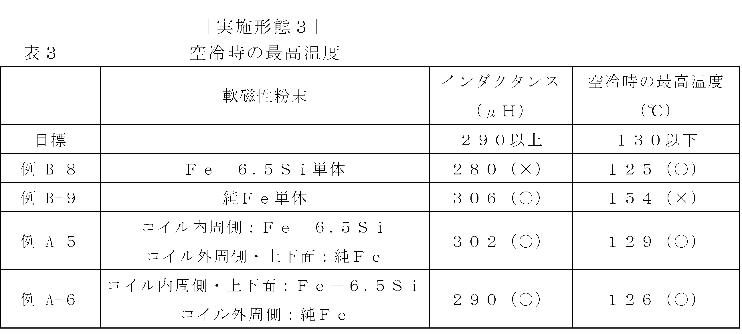
従ってそのような場合には底部26を上面部分として、また蓋部34を下面部分として表2及び表3に示すような材料でこれを構成しておく。
次にリアクトルの更に他の実施形態をその製造方法とともに説明する。
この例では、コイル10が、絶縁被膜の付いていない金属単体の平角線材を、線材の厚み方向(径方向)に巻回してコイル形状と成したフラットワイズコイルで、図20(B)に示すように隣合う線材6Aと6Aとの間に樹脂の絶縁膜7Aが介在させてある。ここで絶縁膜7Aは、線材6Aと同幅となしてある。
このコイル10は、次のようにして製造することができる。
この例のコイル10の製造方法では、長尺をなす金属単体の線材6をフラットワイズ巻きする際に、樹脂のフィルム7を挟み込む状態に長尺の線材6をその厚み方向に共巻きして行く。
そのことによって、図20(B)に示すように線材6Aと6Aとの間に樹脂のフィルム7から成る絶縁膜7Aが介在せしめられる。
而して絶縁膜の膜厚を薄くしておくことで、コイル外径を有効に小径化でき、コイルを小型化することができる。
尚、絶縁破壊耐力は材質と厚みにより異なる。比較的入手し易く膜厚が薄いフィルムの厚みと絶縁破壊耐力は以下のようになる。
ポリイミド樹脂のフィルムは厚み12.5μmの下で絶縁破壊耐力400Vであり、ポリアミド樹脂のフィルムは8μmの厚みの下で絶縁破壊耐力200Vを有し、ポリテトラフルオロエチレン樹脂のフィルムは膜厚12μmの下で1500Vの絶縁破壊耐力を有し、更にポリフェニレンサルファイド樹脂のフィルムは膜厚12μmの下で200Vの絶縁破壊耐力を有している。いずれも耐電圧200Vは満足しており、これらのものを用いるのが好ましい。
本実施形態に従って、絶縁被膜の付いていない平角線材を樹脂のフィルムを挟み込む状態に共巻きして、フラットワイズコイル10を構成し、その効果を以下に示す通り確認した。
尚上記以外のリアクトルの構成は次のようにした。
ここでは、コア材の軟磁性粉末としてFe-2Si(質量%)の組成のものを用いた。
コア材の軟磁性粉末としては、アルゴンガスを用いて噴霧した軟磁性粉末を使用し、粉末熱処理は酸化防止や還元作用を狙って水素中で750℃×3時間行った。またコア材として1~50kHzの交番磁界中で使用されることを想定し、軟磁性粉末は粉末熱処理後に250μm以下に篩で篩ったものを使用した。
そして横型インラインスクリュー式射出成形装置により、このペレット状の軟磁性混練物を約300℃で加熱し溶融状態として、これを成形型内に射出した後、冷却してコア材を作製した。
またコイルを上下に2段に段重ねする場合には、上下のコイルの間に0.5mmの厚みの絶縁シートを介在させた。
尚、コア16の軸心とコイル10の軸心、及びコア16の軸方向中央とコイル10の軸方向中央とはそれぞれ一致するように揃えて配置した。
平均膜厚25μmのポリアミドイミド樹脂の絶縁被膜付きの平角銅線(厚み0.85mm(絶縁被膜付きの厚み)×幅9mm)を用いてフラットワイズコイル(内径50mm,32ターン)を構成し、これを樹脂被覆層22で被覆してコイル被覆体24とした。
尚、コイル10は上記の図に示したものと異なって2段に段重ねせず、1段で構成している。この点は後述する例B-3を除いて何れも同じである。
膜厚12.5μmのポリイミド樹脂のフィルムを、圧延で製造した平角裸銅線(厚み0.8mm×幅9mm)の巻線時に線材と線材との間に挟み込んで共巻きし、フラットワイズコイル(内径50mm,32ターン)を構成し、そしてこれを樹脂被覆層22にて被覆してコイル被覆体24とした。
この結果、コイル外径を2.4mm小径化することができた。またその結果、銅線使用量を6%少なくでき、更に樹脂被覆層に用いる樹脂も5%少なくすることができた。
例B-1のコイルを用いてリアクトル(外径φ117.4mm×高さ31mm)を構成した。
上記例A-1のコイルを用いてリアクトル(外径φ115mm×高さ31mm)を構成した。
この例A-2のリアクトルは例B-2と同一インダクタンスである(尚インダクタンスの測定方法は下記とした)。
この例A-2では、リアクトル外径で略2.4mm小径化することができた。その結果コア材使用量も4%少なくすることができた。またリアクトル全体として、体積%で4%小さくでき、重量も4%小さくすることができた。
また、例B-2対比で、重畳電流0A(ゼロアンペア)での損失で4%低減できた。この低減分はほとんどが鉄損低減による効果と推定される。また、重畳電流50Aでの直流銅損で6%低減できた(これらの損失の評価方法は下記)。
平均膜厚25μmのポリアミドイミド樹脂の絶縁被膜付きの平角銅線(厚み1.25mm×幅6mm)を用いて、フラットワイズ巻きしたコイル(内径53mm,16ターン)を上下に2段に段重ねして、全体を樹脂被覆層22にて被覆し、コイル被覆体24とした。そしてこのコイル被覆体を用いてリアクトル(外径φ106mm×高さ34.5mm)を構成した。
膜厚8μmのポリアミド樹脂のフィルムを、圧延で製造した平角裸銅線(厚み0.6mm×幅12mm、扁平度20)の巻線時に線材間に挟み込んで共巻きし、フラットワイズコイル(内径53mm,32ターン)を構成するとともに、その全体を外側から樹脂被覆層22で被覆し、コイル被覆体24とした。
そしてこれを用いてリアクトル(外径φ105mm×高さ34mm)を構成した。このもののインダクタンスは例B-3と同一インダクタンスである。
またスイッチング周波数20kHzで300V→600V昇圧の重畳電流0Aでの損失を25%低減することができた(この損失の評価方法は下記)。この内2~3%分は鉄損低減分と推定されるが、残りの低減分は高偏平平角銅線を用いたことによる表皮効果損の低減によるものと推定される。
膜厚8μmのポリアミド樹脂のフィルムを、圧延で製造した平角裸アルミ線(厚み0.6mm×幅12mm、扁平度20)の巻線時に線材間に挟み込んで共巻きし、フラットワイズコイル(内径53mm,32ターン)を構成するとともに、その全体を外側から樹脂被覆層22で被覆し、コイル被覆体24とした。
そしてこれを用いてリアクトル(外径φ105mm×高さ34mm)を構成した。このもののインダクタンスは例B-3と同一インダクタンスである。
尚上記例A,例Bは全て耐電圧試験及び熱衝撃試験の評価を行い、何れも基準を満たしている。
<インダクタンス測定>
インダクタンスの測定は、リアクトル15を昇圧チョッパ回路に組込み、入力電圧300V、昇圧後電圧600V、スイッチング周波数10kHz(例B-3,例A-3では20kHz)で所定の重畳電流を流して回路を駆動させた。そしてリアクトルに流れる電流(片方の端子にクランプ式電流計を取り付け測定)の波形を測定し、ある時間間隔の電流波形の傾きからインダクタンスを算出した。
損失の測定は以下の方法で行った。
水冷プレート上にリアクトル15を固定した。このとき熱伝導グリスを水冷プレートとの間に薄く塗布した。
重畳電流0A及び50Aで300V→600Vにスイッチング周波数10kHz(例B-3、例A-3は20kHz)の条件でインダクタンス測定と同じ昇圧チョッパ回路で駆動させ、熱的に定常状態(コアの内部温度や冷却水温が時間的に変化しなくなる状態)になるまで連続運転した。また冷却水はチラー(恒温水循環装置)で50℃、毎分10リットルで流れるよう制御した。
この時のコア内部の温度を数点測定して、その最も高い温度を内部温度とした。温度の測定箇所には熱電対を埋め込んで測定を行った。
この時の水冷プレートの冷却水の流量と、入側と出側の温度との差から熱量を測定し、この熱量を損失とした。重畳電流0A及び50Aの時のそれぞれの損失の値を求め、重畳電流50Aの時の損失から重畳電流0Aの時の損失を差引いた値を、重畳電流50Aの直流銅損とした。
・コア材の損失(ヒステリシス損失と渦電流損失の和)からくる損失(鉄損)
・リアクトルに流れる電流から直流重畳電流を除いた電流振幅分によるコイルの発熱からくる損失(交流銅損)
・コイルの導線に高周波電流が流れる際に生じる表皮効果からくる損失(表皮効果損)
・隣り合う導線同士が電流の流れを互いに阻害しあう近接効果からくる損失(近接効果損)
これらを正確に分解することは困難であるため、例A、例Bでは、重畳電流0Aでの損失を直接比較している。
耐電圧測定は次のようにして行った。
ここではリアクトル15をアルミベースプレート上に直接置いて、リアクトル15をアルミベースプレートに電気的に繋がった状態とし、そして測定装置の一方の端子をリアクトル15の一方のコイル端子18に、また他方の端子をアルミベースプレートにそれぞれ結線し、そしてその状態で通電を行って交流0V~3500V(ボルト)まで徐々に電圧を高め、3500Vで1秒間保持した。
その際、流れる電流が10mA(ミリアンペア)以下であれば合格、それよりも多ければ不合格として耐電圧を判定した。
熱衝撃試験は次のようにして行った。
(a)[試験方法]:下記熱衝撃試験装置で低温槽を-40℃とし、高温槽を150℃とし、低温さらしと高温さらしとを交互に繰り返し、600サイクル実施した。また、各さらし時間は2時間とした。
(b)[評価基準]:600サイクル後、(i)外観にクラックなきこと。(ii)再度耐電圧試験を実施しクリアできること。(iii)熱衝撃試験前後のインダクタンスの変化が5%以下であること。
(c)[試験装置]:エスペック社製で型式はTSA-41L-Aである。
例えば上記実施形態ではコイル被覆体24を成形するに際し、先ず外周被覆部46を成形し、次いで内周被覆部50を成形するようにしているが、場合によって1次成形ではコイル10を1次成形型にて外周面で保持拘束して内周被覆部50を成形し、その後に外周被覆部46を成形するようになすことも可能であるし、また樹脂被覆層22における1次成形体22-1,2次成形体22-2或いはコア16における1次成形体16-1,2次成形体16-2を上例以外の他の様々な形状で成形するといったことも可能である。
7 樹脂のフィルム
7A 絶縁膜
10 コイル
15 リアクトル
16 コア
16-1,22-1 1次成形体
16-2,22-2 2次成形体
22 樹脂被覆層
24 コイル被覆体
25 外周側成形部
26 底部
30 開口
32 内周側成形部
34 蓋部
40 凹所
46 外周被覆部
50 内周被覆部
54,84 1次成形型
66,80,94,104 キャビティ
70,96 2次成形型
110 容器部
114 アルミケース(リアクトルケース)
P1,P2 境界面
Claims (18)
- 軟磁性粉末と樹脂とを含む混合材で構成した成形体をコアとして、該コアの内部に、線材と線材との間に絶縁層を介在させる状態に該線材を巻いて成る導体コイルを埋込状態に一体化して成るリアクトルであって、
前記コイルを電気絶縁性の樹脂にて外側から全体的に包み込む状態に被覆してコイル被覆体となす一方、
前記コアを、該コイル被覆体を内部に一体に埋め込む状態に前記軟磁性粉末と熱可塑性樹脂とを含む混合材を射出成形して成る成形体にて構成してあることを特徴とするリアクトル。 - 請求項1において、前記コアは、前記コイル被覆体の外周面に接する筒状の外周側成形部を含む1次成形体と、該コイル被覆体の内周面に接する内周側成形部を含む2次成形体とが境界面で接合されて一体化されていることを特徴とするリアクトル。
- 請求項1,2の何れかにおいて、前記コイル被覆体の前記樹脂被覆層は絶縁性の熱可塑性樹脂の射出成形体にて構成してあり、前記コイルの外周面を被覆する外周被覆部を含む成形体と、該コイルの内周面を被覆する内周被覆部を含む成形体とが接合されて一体化されていることを特徴とするリアクトル。
- 請求項1~3の何れかにおいて、前記コイルを平角線材を巻いて成るコイルとなし、該コイルを、複数のコイルブロックを互いに接続状態でコイル軸方向である高さ方向又は/及び径方向に且つ前記線材の巻き重ねの方向と直交方向に絶縁シートを介して同軸状に重ねた形態で構成するとともに該絶縁シート込みの、コイル縦断面における高さ寸法をA,径方向寸法である幅方向寸法をBとしたときのアスペクト比A/Bが0.7~1.8の範囲となしてあることを特徴とするリアクトル。
- 請求項4において、前記コイルが前記平角線材を該線材の厚み方向に巻いて成るフラットワイズコイルで、前記コイルブロックが前記高さ方向に複数段に積み重ねてあることを特徴とするリアクトル。
- 請求項1~5の何れかにおいて、前記軟磁性粉末が純Fe若しくはSiを0.2~9.0質量%含有した組成のFe基合金の粉末であることを特徴とするリアクトル。
- 請求項1~6の何れかにおいて、前記コアにおける前記コイルの内周側部分と外周側部分とを異なった材料で構成してあり、
該外周側部分については、前記軟磁性粉末として純Fe若しくはSiを0.2~4.0質量%含有したFe基合金から成る低Si材の粉末を用いたコア材で構成し、
前記内周側部分については、前記軟磁性粉末としてSiを1.5~9.0質量%含有し且つ前記外周側部分のコア材の軟磁性粉末よりもSi含有量の多いFe基合金から成る高Si材の粉末を用いたコア材で構成してあることを特徴とするリアクトル。 - 請求項7において、前記高Si材のSi含有量が前記低Si材のSi含有量よりも1.5質量%を超えて多いことを特徴とするリアクトル。
- 請求項1~8の何れかにおいて、前記コイルは、絶縁被膜の付いていない平角線材を該線材と線材との間に、予め膜状に成形してある絶縁性のフィルムを挟み込む状態に該線材の厚み方向に巻回したフラットワイズコイルとなしてあることを特徴とするリアクトル。
- 請求項1~9の何れかにおいて、前記コアがリアクトルケースの容器部と一体に射出成形してあることを特徴とするリアクトル。
- 周波数が1~50kHzの交番磁界中で使用されることを特徴とする請求項1~10の何れかに記載のリアクトル。
- 請求項1に記載のリアクトルを製造する方法であって、
前記コイルを外側から全体的に包み込む状態に前記電気絶縁性の樹脂で被覆して前記コイル被覆体を成形する工程Aと、
該コイル被覆体を成形型にセットして、該コイル被覆体を包み込む状態に前記軟磁性粉末と熱可塑性樹脂とを含む混合材を射出成形して前記コアを成形するとともに、該コアの内部に前記コイルを埋込状態に一体化する工程Bと、
を経て前記リアクトルを得ることを特徴とするリアクトルの製造方法。 - 請求項12において、前記コアを射出成形する工程Bを、
該コアの、前記コイル被覆体の外周面に接する筒状の外周側成形部を含む、コイル軸線方向の一端側に該コイル被覆体の嵌込用の開口を有する形状の1次成形体をコア用の1次成形型にて予め射出成形しておく工程B-1と、
該コイル被覆体の内周面に接する内周側成形部を含む2次成形体をコア用の2次成形型にて成形する工程B-2と、に分け、
該工程B-2では、前記工程B-1で得た前記1次成形体の前記外周側成形部に前記コイル被覆体を内嵌状態に嵌合させ且つ前記コア用の2次成形型にて該外周側成形部を外周側から径方向に拘束し保持した状態で、前記内周側成形部を含む2次成形体を成形すると同時に、該2次成形体と前記1次成形体及び前記コイル被覆体を一体化することを特徴とするリアクトルの製造方法。 - 請求項13において、前記1次成形体を成形する前記工程B-1では、前記外周側成形部とともに前記開口とは反対側の前記コアの底部を併せて成形して、該1次成形体を前記コイル被覆体を内部に収容し保持する底部付きの容器状となしておくことを特徴とするリアクトルの製造方法。
- 請求項14において、前記1次成形体は、前記コイル被覆体を内部の凹所に全高に亘って収容する高さで成形しておくことを特徴とするリアクトルの製造方法。
- 請求項13~15の何れかにおいて、前記2次成形体を成形する前記工程B-2では、前記内周側成形部とともに前記開口を閉鎖する蓋部を併せて成形することを特徴とするリアクトルの製造方法。
- 請求項12~16の何れかにおいて、前記コイル被覆体を成形する工程Aでは、該コイルを包み込む状態に被覆する樹脂被覆層を熱可塑性樹脂にて射出成形するとともに、該工程Aを、
前記コイルの内周面又は外周面に対して該樹脂被覆層用の1次成形型を接触させ、該1次成形型にて該コイルを該内周面又は外周面において径方向に位置決めし拘束した状態で、該コイルの外周側又は内周側に形成される該1次成形型の1次成形キャビティに樹脂材料を射出して、前記樹脂被覆層における外周被覆部又は内周被覆部を含む1次成形体を成形し且つ該コイルと一体化する工程A-1と、
しかる後該1次成形体を該コイルとともに該樹脂被覆層用の2次成形型にセットして、該コイルの内周側又は外周側に形成される該2次成形型の2次成形キャビティに前記樹脂材料を射出して、前記樹脂被覆層における内周被覆部又は外周被覆部を含む2次成形体を成形し且つ該コイル及び前記1次成形体と一体化する工程A-2と、
に分けて射出成形を行うことを特徴とするリアクトルの製造方法。 - 請求項12~17の何れかにおいて、長尺をなす平角線材を、該平角線材に対応した幅で予め長尺の膜状に成形してある絶縁性のフィルムとともに且つ該フィルムを該線材と線材との間に挟み込むようにして共巻し、前記コイルを得ることを特徴とするリアクトルの製造方法。
Priority Applications (5)
| Application Number | Priority Date | Filing Date | Title |
|---|---|---|---|
| CA2793830A CA2793830A1 (en) | 2010-03-20 | 2011-03-17 | Reactor and method of manufacture for same |
| US13/636,099 US20130008890A1 (en) | 2010-03-20 | 2011-03-17 | Reactor method of manufacture for same |
| EP11759313.7A EP2551863A4 (en) | 2010-03-20 | 2011-03-17 | REACTOR AND METHOD FOR MANUFACTURING THE SAME |
| CN2011800149716A CN102822918A (zh) | 2010-03-20 | 2011-03-17 | 电抗器及其制造方法 |
| KR1020127024645A KR20130006459A (ko) | 2010-03-20 | 2011-03-17 | 리액터 및 그 제조 방법 |
Applications Claiming Priority (8)
| Application Number | Priority Date | Filing Date | Title |
|---|---|---|---|
| JP2010065310A JP5418342B2 (ja) | 2010-03-20 | 2010-03-20 | リアクトル |
| JP2010065309A JP5556285B2 (ja) | 2010-03-20 | 2010-03-20 | リアクトル |
| JP2010-065309 | 2010-03-20 | ||
| JP2010065307A JP5556284B2 (ja) | 2010-03-20 | 2010-03-20 | コイル複合成形体の製造方法及びコイル複合成形体 |
| JP2010-065307 | 2010-03-20 | ||
| JP2010-065310 | 2010-03-20 | ||
| JP2010-107793 | 2010-05-08 | ||
| JP2010107793A JP2011238716A (ja) | 2010-05-08 | 2010-05-08 | リアクトル及びその製造方法 |
Publications (1)
| Publication Number | Publication Date |
|---|---|
| WO2011118507A1 true WO2011118507A1 (ja) | 2011-09-29 |
Family
ID=44673064
Family Applications (1)
| Application Number | Title | Priority Date | Filing Date |
|---|---|---|---|
| PCT/JP2011/056473 Ceased WO2011118507A1 (ja) | 2010-03-20 | 2011-03-17 | リアクトル及びその製造方法 |
Country Status (6)
| Country | Link |
|---|---|
| US (1) | US20130008890A1 (ja) |
| EP (1) | EP2551863A4 (ja) |
| KR (1) | KR20130006459A (ja) |
| CN (1) | CN102822918A (ja) |
| CA (1) | CA2793830A1 (ja) |
| WO (1) | WO2011118507A1 (ja) |
Cited By (3)
| Publication number | Priority date | Publication date | Assignee | Title |
|---|---|---|---|---|
| WO2014203809A1 (ja) * | 2013-06-17 | 2014-12-24 | 住友電気工業株式会社 | リアクトル、磁性体、コンバータ、および電力変換装置 |
| JP2017123407A (ja) * | 2016-01-07 | 2017-07-13 | 株式会社オートネットワーク技術研究所 | 複合材料成形体、リアクトル、及び複合材料成形体の製造方法 |
| WO2022130583A1 (ja) * | 2020-12-17 | 2022-06-23 | 日新電機株式会社 | リアクトルの温度上昇試験方法 |
Families Citing this family (27)
| Publication number | Priority date | Publication date | Assignee | Title |
|---|---|---|---|---|
| US9141157B2 (en) * | 2011-10-13 | 2015-09-22 | Texas Instruments Incorporated | Molded power supply system having a thermally insulated component |
| US9136213B2 (en) * | 2012-08-02 | 2015-09-15 | Infineon Technologies Ag | Integrated system and method of making the integrated system |
| US20150332839A1 (en) * | 2012-12-21 | 2015-11-19 | Robert Bosch Gmbh | Inductive charging coil device |
| JP6065609B2 (ja) * | 2013-01-28 | 2017-01-25 | 住友電気工業株式会社 | リアクトル、コンバータ、及び電力変換装置 |
| EP2797090A1 (en) * | 2013-04-25 | 2014-10-29 | Magnetic Components Sweden AB | Thermal management system for SMC inductors |
| WO2014184105A1 (en) * | 2013-05-13 | 2014-11-20 | Höganäs Ab (Publ) | Inductor |
| KR101525216B1 (ko) * | 2013-07-08 | 2015-06-04 | 주식회사 한국다무라 | 하이브리드 리액터 |
| TW201603071A (zh) * | 2014-02-25 | 2016-01-16 | 好根那公司 | 感應器 |
| CN104979079A (zh) * | 2014-04-08 | 2015-10-14 | 浙江科达磁电有限公司 | 一种罐型磁芯单体及包含它的罐型磁芯 |
| JP6649676B2 (ja) * | 2014-10-03 | 2020-02-19 | 株式会社三井ハイテック | 積層鉄心の製造方法 |
| DE112016003964T5 (de) * | 2015-09-01 | 2018-05-17 | Mitsubishi Electric Corporation | Leistungswandler |
| JP6687881B2 (ja) * | 2015-12-02 | 2020-04-28 | Tdk株式会社 | コイル装置 |
| CN106098296A (zh) * | 2016-06-02 | 2016-11-09 | 横店集团东磁股份有限公司 | 一体成型电感及其制造方法 |
| JP6621056B2 (ja) * | 2016-06-10 | 2019-12-18 | 株式会社オートネットワーク技術研究所 | リアクトル、およびリアクトルの製造方法 |
| JP2018056524A (ja) * | 2016-09-30 | 2018-04-05 | Tdk株式会社 | コイル部品 |
| US20180197676A1 (en) * | 2017-01-10 | 2018-07-12 | General Electric Company | Insulation for tranformer or inductor |
| WO2018215064A1 (en) * | 2017-05-24 | 2018-11-29 | Vacon Oy | Inductor and method for producing the same |
| JP7198396B2 (ja) * | 2017-12-28 | 2023-01-04 | 株式会社セキデン | 中空芯コイル及びその製造方法 |
| CN110246674B (zh) * | 2019-03-15 | 2020-12-01 | 江苏五洲电力科技有限公司 | 一种电抗器扇形铁心饼成型方法 |
| DE102019209141A1 (de) * | 2019-06-25 | 2020-12-31 | Mahle International Gmbh | Verfahren zur Herstellung einer induktiven Ladeeinrichtung |
| JP7268508B2 (ja) * | 2019-07-09 | 2023-05-08 | 株式会社デンソー | コイルモジュール及び電力変換装置 |
| DE102020114516A1 (de) * | 2020-05-29 | 2021-12-02 | Tdk Electronics Ag | Spulenelement |
| CN112873735B (zh) * | 2020-12-07 | 2023-02-24 | 台达电子企业管理(上海)有限公司 | 一种应用于磁性元件塑胶体的制造方法以及塑胶体 |
| CN114078633B (zh) * | 2022-01-07 | 2022-04-05 | 苏州市全力自动化科技有限公司 | 一种全自动小型电磁阀线圈装配线 |
| CN114639542B (zh) * | 2022-03-11 | 2022-11-22 | 华中科技大学 | 一种螺旋式成形线圈的自动化绕制加固装置及方法 |
| KR102716350B1 (ko) * | 2022-07-15 | 2024-10-15 | 주식회사 필리퍼 | 고온 성형에 의한 Fe-xSi(x=4-10.0wt%) 합금 압분자심 코어의 제조 방법 |
| CN117685869B (zh) * | 2024-02-02 | 2024-05-31 | 南京立业电力变压器有限公司 | 一种在变压器器身装配前电抗法检测绕组变形的装置 |
Citations (16)
| Publication number | Priority date | Publication date | Assignee | Title |
|---|---|---|---|---|
| JPS54163354A (en) * | 1978-06-16 | 1979-12-25 | Daido Steel Co Ltd | Coil and method of producing same |
| JPH1050533A (ja) * | 1996-08-07 | 1998-02-20 | Fuji Electric Co Ltd | ガス絶縁誘導電器巻線 |
| JP2000021669A (ja) | 1998-06-30 | 2000-01-21 | Toshiba Corp | 電磁コイルの製造方法及びその装置 |
| JP2001267136A (ja) * | 2000-03-14 | 2001-09-28 | Murata Mfg Co Ltd | インダクタ及びその製造方法 |
| JP2002043140A (ja) | 2000-07-21 | 2002-02-08 | Alps Electric Co Ltd | 磁気素子 |
| JP2003282333A (ja) * | 2002-03-27 | 2003-10-03 | Tdk Corp | コイル封入圧粉磁芯 |
| JP2004039888A (ja) * | 2002-07-04 | 2004-02-05 | Matsushita Electric Ind Co Ltd | インダクタ部品 |
| JP2006261331A (ja) | 2005-03-16 | 2006-09-28 | Nec Tokin Corp | インダクタンス部品およびその製造方法 |
| JP2006310550A (ja) | 2005-04-28 | 2006-11-09 | Tamura Seisakusho Co Ltd | ポットコアを使用したリアクトル及び、複合型リアクトル |
| JP2007027185A (ja) | 2005-07-12 | 2007-02-01 | Denso Corp | コイル封止型樹脂成形リアクトル及びその製造方法 |
| JP2007096181A (ja) | 2005-09-30 | 2007-04-12 | Tokyo Parts Ind Co Ltd | 面実装型インダクタ |
| JP2007305665A (ja) | 2006-05-09 | 2007-11-22 | Sumida Corporation | インダクタ |
| JP2008147405A (ja) | 2006-12-08 | 2008-06-26 | Sumitomo Electric Ind Ltd | 軟磁性複合材料の製造方法 |
| JP2008192649A (ja) | 2007-01-31 | 2008-08-21 | Denso Corp | ハイブリッド車両用リアクトル |
| JP2009224745A (ja) | 2008-03-17 | 2009-10-01 | Qiankun Kagi Kofun Yugenkoshi | インダクタ及びその製作方法 |
| JP2010214590A (ja) * | 2009-03-12 | 2010-09-30 | Daido Electronics Co Ltd | 複合成形体の製造方法 |
Family Cites Families (9)
| Publication number | Priority date | Publication date | Assignee | Title |
|---|---|---|---|---|
| US6248279B1 (en) * | 1999-05-25 | 2001-06-19 | Panzer Tool Works, Inc. | Method and apparatus for encapsulating a ring-shaped member |
| DE10024824A1 (de) * | 2000-05-19 | 2001-11-29 | Vacuumschmelze Gmbh | Induktives Bauelement und Verfahren zu seiner Herstellung |
| JP2002083732A (ja) * | 2000-09-08 | 2002-03-22 | Murata Mfg Co Ltd | インダクタ及びその製造方法 |
| JP2004281778A (ja) * | 2003-03-17 | 2004-10-07 | Tokyo Coil Engineering Kk | チョークコイル及びその製造方法 |
| US20050007232A1 (en) * | 2003-06-12 | 2005-01-13 | Nec Tokin Corporation | Magnetic core and coil component using the same |
| JP4851062B2 (ja) * | 2003-12-10 | 2012-01-11 | スミダコーポレーション株式会社 | インダクタンス素子の製造方法 |
| EP2026362A1 (en) * | 2007-08-07 | 2009-02-18 | ABC Taiwan Electronics Corp. | Shielded-type inductor |
| JP5197220B2 (ja) * | 2008-08-07 | 2013-05-15 | 株式会社デンソー | リアクトルの製造方法 |
| CN101673609A (zh) * | 2008-09-09 | 2010-03-17 | 鸿富锦精密工业(深圳)有限公司 | 电感器及其上的电感线圈 |
-
2011
- 2011-03-17 WO PCT/JP2011/056473 patent/WO2011118507A1/ja not_active Ceased
- 2011-03-17 CN CN2011800149716A patent/CN102822918A/zh active Pending
- 2011-03-17 US US13/636,099 patent/US20130008890A1/en not_active Abandoned
- 2011-03-17 EP EP11759313.7A patent/EP2551863A4/en not_active Withdrawn
- 2011-03-17 CA CA2793830A patent/CA2793830A1/en not_active Abandoned
- 2011-03-17 KR KR1020127024645A patent/KR20130006459A/ko not_active Withdrawn
Patent Citations (16)
| Publication number | Priority date | Publication date | Assignee | Title |
|---|---|---|---|---|
| JPS54163354A (en) * | 1978-06-16 | 1979-12-25 | Daido Steel Co Ltd | Coil and method of producing same |
| JPH1050533A (ja) * | 1996-08-07 | 1998-02-20 | Fuji Electric Co Ltd | ガス絶縁誘導電器巻線 |
| JP2000021669A (ja) | 1998-06-30 | 2000-01-21 | Toshiba Corp | 電磁コイルの製造方法及びその装置 |
| JP2001267136A (ja) * | 2000-03-14 | 2001-09-28 | Murata Mfg Co Ltd | インダクタ及びその製造方法 |
| JP2002043140A (ja) | 2000-07-21 | 2002-02-08 | Alps Electric Co Ltd | 磁気素子 |
| JP2003282333A (ja) * | 2002-03-27 | 2003-10-03 | Tdk Corp | コイル封入圧粉磁芯 |
| JP2004039888A (ja) * | 2002-07-04 | 2004-02-05 | Matsushita Electric Ind Co Ltd | インダクタ部品 |
| JP2006261331A (ja) | 2005-03-16 | 2006-09-28 | Nec Tokin Corp | インダクタンス部品およびその製造方法 |
| JP2006310550A (ja) | 2005-04-28 | 2006-11-09 | Tamura Seisakusho Co Ltd | ポットコアを使用したリアクトル及び、複合型リアクトル |
| JP2007027185A (ja) | 2005-07-12 | 2007-02-01 | Denso Corp | コイル封止型樹脂成形リアクトル及びその製造方法 |
| JP2007096181A (ja) | 2005-09-30 | 2007-04-12 | Tokyo Parts Ind Co Ltd | 面実装型インダクタ |
| JP2007305665A (ja) | 2006-05-09 | 2007-11-22 | Sumida Corporation | インダクタ |
| JP2008147405A (ja) | 2006-12-08 | 2008-06-26 | Sumitomo Electric Ind Ltd | 軟磁性複合材料の製造方法 |
| JP2008192649A (ja) | 2007-01-31 | 2008-08-21 | Denso Corp | ハイブリッド車両用リアクトル |
| JP2009224745A (ja) | 2008-03-17 | 2009-10-01 | Qiankun Kagi Kofun Yugenkoshi | インダクタ及びその製作方法 |
| JP2010214590A (ja) * | 2009-03-12 | 2010-09-30 | Daido Electronics Co Ltd | 複合成形体の製造方法 |
Non-Patent Citations (1)
| Title |
|---|
| See also references of EP2551863A4 * |
Cited By (7)
| Publication number | Priority date | Publication date | Assignee | Title |
|---|---|---|---|---|
| WO2014203809A1 (ja) * | 2013-06-17 | 2014-12-24 | 住友電気工業株式会社 | リアクトル、磁性体、コンバータ、および電力変換装置 |
| JP2015026819A (ja) * | 2013-06-17 | 2015-02-05 | 住友電気工業株式会社 | リアクトル、磁性体、コンバータ、および電力変換装置 |
| JP2017123407A (ja) * | 2016-01-07 | 2017-07-13 | 株式会社オートネットワーク技術研究所 | 複合材料成形体、リアクトル、及び複合材料成形体の製造方法 |
| WO2017119439A1 (ja) * | 2016-01-07 | 2017-07-13 | 株式会社オートネットワーク技術研究所 | 複合材料成形体、リアクトル、及び複合材料成形体の製造方法 |
| WO2022130583A1 (ja) * | 2020-12-17 | 2022-06-23 | 日新電機株式会社 | リアクトルの温度上昇試験方法 |
| JPWO2022130583A1 (ja) * | 2020-12-17 | 2022-06-23 | ||
| JP7328601B2 (ja) | 2020-12-17 | 2023-08-17 | 日新電機株式会社 | リアクトルの温度上昇試験方法 |
Also Published As
| Publication number | Publication date |
|---|---|
| CN102822918A (zh) | 2012-12-12 |
| EP2551863A4 (en) | 2015-01-21 |
| EP2551863A1 (en) | 2013-01-30 |
| CA2793830A1 (en) | 2011-09-29 |
| US20130008890A1 (en) | 2013-01-10 |
| KR20130006459A (ko) | 2013-01-16 |
Similar Documents
| Publication | Publication Date | Title |
|---|---|---|
| WO2011118507A1 (ja) | リアクトル及びその製造方法 | |
| JP6090165B2 (ja) | 射出成形リアクトル及びこれに用いるコンパウンド | |
| JP6090164B2 (ja) | リアクトル及びこれに用いるコンパウンド | |
| JP6065923B2 (ja) | 被覆コイル成形体の製造方法及び被覆コイル成形体 | |
| CN109923627B (zh) | 电感元件及其制造方法 | |
| US8686820B2 (en) | Reactor | |
| CN101790766B (zh) | 线圈零件以及该线圈零件的制造方法 | |
| JP5418342B2 (ja) | リアクトル | |
| CN102782783B (zh) | 电抗器和制造电抗器的方法 | |
| JP2011238699A (ja) | ケース付リアクトルの製造方法及びケース付リアクトル | |
| CN103098153A (zh) | 电抗器及制造该电抗器的方法 | |
| JP2016143827A (ja) | 複合材料、磁気部品用の磁性コア、リアクトル、コンバータ、及び電力変換装置 | |
| JP5556285B2 (ja) | リアクトル | |
| JP5556284B2 (ja) | コイル複合成形体の製造方法及びコイル複合成形体 | |
| JP2011238716A (ja) | リアクトル及びその製造方法 | |
| US10825591B2 (en) | Composite material molded article and reactor | |
| JP2005005644A (ja) | 巻線型電子部品及び樹脂組成物 | |
| JP6087708B2 (ja) | 巻線素子の製造方法 | |
| US20250308757A1 (en) | Coil component | |
| WO2026083660A1 (ja) | インダクタおよびインダクタの製造方法 |
Legal Events
| Date | Code | Title | Description |
|---|---|---|---|
| WWE | Wipo information: entry into national phase |
Ref document number: 201180014971.6 Country of ref document: CN |
|
| 121 | Ep: the epo has been informed by wipo that ep was designated in this application |
Ref document number: 11759313 Country of ref document: EP Kind code of ref document: A1 |
|
| ENP | Entry into the national phase |
Ref document number: 2793830 Country of ref document: CA |
|
| WWE | Wipo information: entry into national phase |
Ref document number: 13636099 Country of ref document: US |
|
| ENP | Entry into the national phase |
Ref document number: 20127024645 Country of ref document: KR Kind code of ref document: A |
|
| NENP | Non-entry into the national phase |
Ref country code: DE |
|
| REEP | Request for entry into the european phase |
Ref document number: 2011759313 Country of ref document: EP |
|
| WWE | Wipo information: entry into national phase |
Ref document number: 2011759313 Country of ref document: EP |