WO2011118559A1 - 太陽電池モジュール - Google Patents
太陽電池モジュール Download PDFInfo
- Publication number
- WO2011118559A1 WO2011118559A1 PCT/JP2011/056747 JP2011056747W WO2011118559A1 WO 2011118559 A1 WO2011118559 A1 WO 2011118559A1 JP 2011056747 W JP2011056747 W JP 2011056747W WO 2011118559 A1 WO2011118559 A1 WO 2011118559A1
- Authority
- WO
- WIPO (PCT)
- Prior art keywords
- solar cell
- cell module
- support member
- main plate
- support
- Prior art date
- Legal status (The legal status is an assumption and is not a legal conclusion. Google has not performed a legal analysis and makes no representation as to the accuracy of the status listed.)
- Ceased
Links
Images












Classifications
-
- H—ELECTRICITY
- H02—GENERATION; CONVERSION OR DISTRIBUTION OF ELECTRIC POWER
- H02S—GENERATION OF ELECTRIC POWER BY CONVERSION OF INFRARED RADIATION, VISIBLE LIGHT OR ULTRAVIOLET LIGHT, e.g. USING PHOTOVOLTAIC [PV] MODULES
- H02S20/00—Supporting structures for PV modules
- H02S20/20—Supporting structures directly fixed to an immovable object
- H02S20/22—Supporting structures directly fixed to an immovable object specially adapted for buildings
- H02S20/23—Supporting structures directly fixed to an immovable object specially adapted for buildings specially adapted for roof structures
-
- F—MECHANICAL ENGINEERING; LIGHTING; HEATING; WEAPONS; BLASTING
- F24—HEATING; RANGES; VENTILATING
- F24S—SOLAR HEAT COLLECTORS; SOLAR HEAT SYSTEMS
- F24S25/00—Arrangement of stationary mountings or supports for solar heat collector modules
- F24S25/10—Arrangement of stationary mountings or supports for solar heat collector modules extending in directions away from a supporting surface
- F24S25/13—Profile arrangements, e.g. trusses
-
- F—MECHANICAL ENGINEERING; LIGHTING; HEATING; WEAPONS; BLASTING
- F24—HEATING; RANGES; VENTILATING
- F24S—SOLAR HEAT COLLECTORS; SOLAR HEAT SYSTEMS
- F24S25/00—Arrangement of stationary mountings or supports for solar heat collector modules
- F24S25/60—Fixation means, e.g. fasteners, specially adapted for supporting solar heat collector modules
- F24S25/63—Fixation means, e.g. fasteners, specially adapted for supporting solar heat collector modules for fixing modules or their peripheral frames to supporting elements
- F24S25/634—Clamps; Clips
- F24S25/636—Clamps; Clips clamping by screw-threaded elements
-
- F—MECHANICAL ENGINEERING; LIGHTING; HEATING; WEAPONS; BLASTING
- F24—HEATING; RANGES; VENTILATING
- F24S—SOLAR HEAT COLLECTORS; SOLAR HEAT SYSTEMS
- F24S25/00—Arrangement of stationary mountings or supports for solar heat collector modules
- F24S25/60—Fixation means, e.g. fasteners, specially adapted for supporting solar heat collector modules
- F24S25/65—Fixation means, e.g. fasteners, specially adapted for supporting solar heat collector modules for coupling adjacent supporting elements, e.g. for connecting profiles together
-
- H—ELECTRICITY
- H02—GENERATION; CONVERSION OR DISTRIBUTION OF ELECTRIC POWER
- H02S—GENERATION OF ELECTRIC POWER BY CONVERSION OF INFRARED RADIATION, VISIBLE LIGHT OR ULTRAVIOLET LIGHT, e.g. USING PHOTOVOLTAIC [PV] MODULES
- H02S20/00—Supporting structures for PV modules
- H02S20/10—Supporting structures directly fixed to the ground
-
- Y—GENERAL TAGGING OF NEW TECHNOLOGICAL DEVELOPMENTS; GENERAL TAGGING OF CROSS-SECTIONAL TECHNOLOGIES SPANNING OVER SEVERAL SECTIONS OF THE IPC; TECHNICAL SUBJECTS COVERED BY FORMER USPC CROSS-REFERENCE ART COLLECTIONS [XRACs] AND DIGESTS
- Y02—TECHNOLOGIES OR APPLICATIONS FOR MITIGATION OR ADAPTATION AGAINST CLIMATE CHANGE
- Y02B—CLIMATE CHANGE MITIGATION TECHNOLOGIES RELATED TO BUILDINGS, e.g. HOUSING, HOUSE APPLIANCES OR RELATED END-USER APPLICATIONS
- Y02B10/00—Integration of renewable energy sources in buildings
- Y02B10/10—Photovoltaic [PV]
-
- Y—GENERAL TAGGING OF NEW TECHNOLOGICAL DEVELOPMENTS; GENERAL TAGGING OF CROSS-SECTIONAL TECHNOLOGIES SPANNING OVER SEVERAL SECTIONS OF THE IPC; TECHNICAL SUBJECTS COVERED BY FORMER USPC CROSS-REFERENCE ART COLLECTIONS [XRACs] AND DIGESTS
- Y02—TECHNOLOGIES OR APPLICATIONS FOR MITIGATION OR ADAPTATION AGAINST CLIMATE CHANGE
- Y02E—REDUCTION OF GREENHOUSE GAS [GHG] EMISSIONS, RELATED TO ENERGY GENERATION, TRANSMISSION OR DISTRIBUTION
- Y02E10/00—Energy generation through renewable energy sources
- Y02E10/40—Solar thermal energy, e.g. solar towers
- Y02E10/47—Mountings or tracking
-
- Y—GENERAL TAGGING OF NEW TECHNOLOGICAL DEVELOPMENTS; GENERAL TAGGING OF CROSS-SECTIONAL TECHNOLOGIES SPANNING OVER SEVERAL SECTIONS OF THE IPC; TECHNICAL SUBJECTS COVERED BY FORMER USPC CROSS-REFERENCE ART COLLECTIONS [XRACs] AND DIGESTS
- Y02—TECHNOLOGIES OR APPLICATIONS FOR MITIGATION OR ADAPTATION AGAINST CLIMATE CHANGE
- Y02E—REDUCTION OF GREENHOUSE GAS [GHG] EMISSIONS, RELATED TO ENERGY GENERATION, TRANSMISSION OR DISTRIBUTION
- Y02E10/00—Energy generation through renewable energy sources
- Y02E10/50—Photovoltaic [PV] energy
Definitions
- the present invention relates to a solar cell module including a solar cell panel having a laminated glass structure in which solar cells that photoelectrically convert sunlight are interposed between a light-receiving surface glass and a back glass.
- a solar cell module which is a structure, is fixedly supported on a gantry.
- this mount for example, there is a structure in which a plurality of bars are arranged and fixed in parallel, a plurality of solar cell modules are bridged between the bars, and each solar cell module is supported.
- Patent Document 1 hooks for fixing are provided at a plurality of locations on the crosspiece, engagement recesses are formed at a plurality of locations of the frame of the solar cell module, and each engagement recess of the frame of the solar cell module is formed. Is engaged with each fixing hook on the crosspiece to fix the solar cell module, thereby simplifying the work.
- Patent Document 1 a plurality of crosspieces and a plurality of support members are combined in a cross-beam shape to construct a frame for a solar cell module, and the solar cell module is also reinforced around the solar cell panel with a frame.
- both modules have sufficient strength, the total number of parts is unnecessarily large and the total weight is heavy when the entire photovoltaic power generation system is viewed.
- the solar cell module holds the periphery of the solar cell panel with a frame
- the arrangement interval of the solar cell panel itself is increased by the amount of the frame, and the solar cell There was a problem that the installation efficiency of a panel fell.
- the presence of the frame increases the weight of the solar cell module itself and increases the outer shape, which makes it difficult for the operator to perform the installation work alone and reduces the work efficiency of the installation work on the gantry. there were.
- Patent Document 1 the solar cell module is moved downward on an inclined surface such as a roof, and each engagement recess of the frame of the solar cell module is engaged with each fixing hook on the crosspiece.
- the operation of moving the heavy solar cell module in the downward tilt direction is not easy and dangerous.
- the engagement recesses of the frame of the solar cell module may not be engaged with the fixing hooks.
- the solar cell module easily slides down. There was also a problem that the risk of work increased.
- the present invention was devised to solve such problems, and its purpose is to reduce the size and weight by eliminating the frame surrounding the solar cell panel, thereby improving the installation efficiency of the solar cell panel.
- Another object of the present invention is to provide a solar cell module that improves the workability of installation work on a gantry.
- a solar cell module of the present invention includes a solar cell panel having a laminated glass structure in which solar cells that photoelectrically convert sunlight are interposed between a light-receiving surface glass and a back glass.
- the module is characterized in that a long support member is arranged and fixed along the longitudinal direction of the solar cell panel on the surface of the back glass.
- the long support member arranged and fixed on the surface of the back glass also functions as a member for maintaining the strength of the back glass, so that the strength of the entire solar cell panel is maintained. Can do.
- a plurality of the support members may be arranged at intervals in the short direction of the solar cell panel.
- the end of the support member may be provided so as to protrude from the end of the solar cell panel.
- an engaging portion may be provided at the protruding end of the support member.
- the support member includes a long main plate, side plates bent downward from both sides along the longitudinal direction of the main plate, and both longitudinal ends of the main plate. It can be set as the structure provided with the engaging part each bent upwards.
- the support member when the support member is formed in a substantially light groove-shaped steel shape, the support member is attached to the gantry and the entire solar cell panel is supported by this support member, the load of the solar cell panel In contrast, the supporting member can be kept at a sufficient strength.
- the support member includes an elongated main plate, side plates bent downward from both side portions along the longitudinal direction of the main plate, and inward from the lower end portions of the side plates. And a bent bottom plate, an inner plate bent upward from the opposite inner end of each bottom plate, and an engagement portion bent upward at both longitudinal ends of the main plate. be able to.
- the support member when the support member is attached to the gantry and the entire solar cell panel is supported by this support member, the support member can be maintained at a sufficient strength against the load of the solar cell panel. It is possible to withstand sufficient use.
- a part of both end portions in the longitudinal direction of the side plate can be cut out in an L shape.
- the support member may be configured to be bonded and fixed to the back glass of the solar cell panel by a double-sided tape having adhesive layers on both sides of the cushion member.
- a double-sided tape having an adhesive layer on both sides of the cushion member is used to fix the solar cell panel and the support member.
- the thickness of the light-receiving surface glass may be thinner than the thickness of the back glass.
- the outer dimension of the front glass may be smaller than the outer dimension of the rear glass, or may be formed in the same shape.
- the gantry It is the end portion of the thick rear glass that may hit the end portion of the next solar cell module to be mounted next to the fixture for fixing to. In other words, it is less likely that the end of a solar cell module placed adjacent to a fixture or adjacent solar cell will come into contact with a thin surface glass (that is, low strength). The possibility of damage to the glass can be reduced.
- the long support member arranged and fixed on the surface of the back glass functions also as a member for maintaining the strength of the back glass, the strength of the entire solar cell panel can be maintained. .
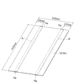
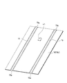
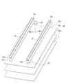
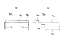
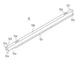
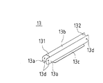
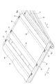
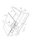
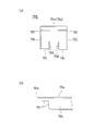
- FIG. 1 It is a perspective view which shows the whole structure of the photovoltaic power generation system of the state which mounted the solar cell module on the mount frame. It is the perspective view which looked at the solar cell module from the light-receiving surface side. It is the perspective view which looked at the solar cell module from the back surface side on the opposite side to a light-receiving surface. It is the disassembled perspective view which looked at the solar cell module from the back side. It is a perspective view which shows the supporting member which comprises a solar cell module. (A), (b), (c) is the front view, side view, and sectional drawing which expand and show the edge part of a supporting member. It is a perspective view which expands and shows the edge part vicinity of the supporting member in a solar cell module.
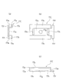
- (A), (b) is the front view and side view which show the other shape of the supporting member which comprises a solar cell module.
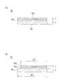
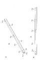
- (A), (b) is a partial expanded sectional view of a solar cell panel. It is a perspective view which shows the base crosspiece which comprises the mount frame of FIG. It is a perspective view which shows the arm which comprises the mount frame of FIG. (A), (b) is the perspective view and top view which show the vertical beam which comprises the mount frame shown in FIG. (A), (b) is the perspective view and top view which show the crosspiece member of the horizontal rail which comprises the mount frame shown in FIG. It is a perspective view which shows the other crosspiece member of the horizontal crosspiece which comprises the mount frame of FIG.
- (A), (b) is the perspective view and front view which show the triangular structure which consists of a base crosspiece, an arm, and a vertical crosspiece. It is sectional drawing which shows the connection structure of an arm and a base crosspiece. It is a perspective view which shows the attachment bracket used for connecting and fixing a horizontal crosspiece to a vertical crosspiece. It is a perspective view which shows the state which attached the attachment bracket of FIG. 17 to the vertical bar. It is sectional drawing which shows the state which connected the horizontal crosspiece to the vertical crosspiece. It is a perspective view which shows the connection structure of each crosspiece member. It is a perspective view which shows the guide support tool which comprises the mount frame of FIG. FIG.
- FIG. 22 is a front view, a plan view, and a side view of the guide support shown in FIG. 21. It is a perspective view which shows the attachment bracket used in order to fix a guide support to a crosspiece. It is a perspective view which shows the state which attached the mounting bracket of FIG. 18 to the crosspiece. It is a perspective view which shows the fixing structure of the guide support using an attachment metal fitting. It is sectional drawing which shows the fixing structure of FIG. It is a disassembled perspective view which shows the fixing structure of the guide support using an attachment metal fitting. It is a perspective view which shows the main structures of the mount frame of this embodiment. It is a perspective view which shows the operation
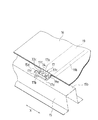
- FIG. 30 is a partially enlarged perspective view of the periphery of the guide support in the gantry shown in FIG. 29.
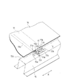
- FIG. 29 is a perspective view showing a part of the periphery of the guide support that supports the last-order solar cell module in the gantry shown in FIG. 28 in an enlarged manner.
- It is a perspective view which partially enlarges and shows the periphery of a guide support including a structure that prevents the support member supported by the guide support from sliding in the ascending order.
- It is a perspective view which partially enlarges and shows the periphery of a guide support including a structure that prevents the support member supported by the guide support from sliding in the ascending order.
- FIG. 42 is a front view, a plan view, and a side view of the guide support shown in FIG. 41.
- FIG. It is a perspective view which shows the fixing structure of the guide support using an attachment metal fitting.
- It is sectional drawing which shows the fixing structure of FIG. It is a disassembled perspective view which shows the fixing structure of the guide support using an attachment metal fitting.
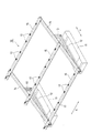
- FIG. 1 is a perspective view showing an overall configuration of a photovoltaic power generation system in a state in which a plurality of solar cell modules 16 according to the present invention are placed on a gantry 10.
- the solar power generation system of this embodiment has a structure that can be used as, for example, a power plant.
- the gantry 10 is roughly divided into a concrete foundation 11, a base beam 12, an arm 13, a vertical beam 14, and a horizontal beam 15. It is configured.
- a plurality of concrete foundations 11 are laid on the ground at equal intervals, and base bars 12 are arranged in parallel at equal intervals on the upper surface 111 of each concrete foundation 11 and fixed.
- the arm 13 is connected to the rear end portion 121 of each base crosspiece 12 so as to stand upright, and the vertical crosspiece 14 is bridged obliquely between the front end portion 122 of each base crosspiece 12 and the upper end portion of each arm 13.
- three horizontal bars 15 are arranged so as to be orthogonal to the vertical bars 14, and the horizontal bars 15 are arranged side by side on the vertical bars 14.
- the horizontal rails 14 are arranged at different heights along the inclination of the vertical rails 14, and the longitudinal ends of the solar cell module 16 are bridged between the adjacent horizontal rails 15.
- the solar cell module 16 is placed in an inclined state. And it is the structure which supports and fixes the both ends of the solar cell module 16 by attaching the guide support tool 17 (refer FIG. 25 etc.) mentioned later to the predetermined
- a plurality of solar cell modules 16 are placed in a horizontal row between the lower horizontal beam 15 and the central horizontal beam 15.
- a plurality of solar cell modules 16 are placed in a horizontal row between the upper horizontal rail 15.
- a plurality of solar cell modules 16 are arranged in two rows on the top and bottom of the three horizontal rails 15.
- three solar cell modules 16 are arranged side by side between two vertical bars 14 adjacent to each other on the left and right.
- the direction in which the concrete foundations 11 are arranged in FIG. 1 is defined as the X direction (left-right direction), and the direction orthogonal to the X direction is defined as the Y direction (front-rear direction).
- FIG. 2 to 4 show the configuration of the solar cell module 16 according to this embodiment.
- FIG. 2 is a perspective view seen from the light receiving surface side
- FIG. 3 is seen from the back side opposite to the light receiving surface.
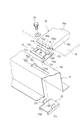
- FIG. 4 is an exploded perspective view as seen from the back side.
- the solar cell module 16 of the present embodiment includes a solar cell panel 18 and two support members 19 that also serve as mounting brackets for the gantry 10.
- the solar battery panel 18 is a solar battery panel having a laminated glass structure in which solar battery cells 18 a that photoelectrically convert sunlight are interposed between a light-receiving surface glass 18 b and a back glass 18 c.
- a long support member 19 formed in a shape that allows the solar cell panel 18 to be attached to the gantry 10 is disposed and fixed along the longitudinal direction of the solar cell panel 16 on the surface of the back glass 18c.
- Two support members 19 are arranged in parallel at a symmetric position with respect to a center line passing through the center in the short direction, with a predetermined interval in the short direction of the solar cell panel 16.
- the arrangement position is arrange
- the solar cell panel 18 has a rectangular shape in a plan view having a longitudinal direction of about 1400 mm and a short side direction of about 1000 mm, and each support member 19 is about 200 mm inward from each side in the longitudinal direction (however, , Which is not limited to 200 mm).
- the solar cell module 16 can be mounted and fixed on the gantry 10 stably.
- the weight distribution of the solar cell panel 18 concerning the support member 19 can be disperse
- the support member 19 is bonded and fixed to the surface of the back glass 18c of the solar cell panel 18 by a double-sided tape 20 having an adhesive layer on both sides of the cushion member.
- An acrylic pressure-sensitive adhesive layer can be used as the pressure-sensitive adhesive layer.
- the cushion member polyolefin, acrylic rubber, or the like can be used.
- symbol 41 shown in FIG.3 and FIG.4 is a terminal box for pulling out the output lead wire which is not illustrated of the photovoltaic cell 18a from the opening part 18c1 of the back surface glass 18c, and electrically connecting it.
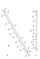
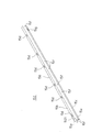
- FIG. 5 is a perspective view showing the support member 19
- FIGS. 6A, 6B, and 6C are a front view, an enlarged side view, a side view, and a sectional view showing the end of the holding member 19
- FIG. 4 is an enlarged perspective view showing the vicinity of an end portion of a support member 19 in the solar cell module 16.
- a support member 19 shown in FIGS. 5 and 6A, 6B, and 6C includes a long main plate 19a and a side plate 19b bent downward from both side portions along the longitudinal direction of the main plate 19a.
- the bottom plate 19c bent inward from the lower end of each side plate 19b, the inner plate 19d bent upward from the opposite inner end of each bottom plate 19c, and the longitudinal ends of the main plate 19a are bent upward.
- L-shaped engaging portion 19e, and the cross-sectional shape thereof is substantially the shape of a lip groove steel.
- the support member 19 is formed in a substantially lip groove steel shape, and the inner side plate 19d is formed by bending the front end side of the lip portion (bottom plate 19c) to the inner package (main plate 19a side), thereby further reinforcing the strength. ing.
- the supporting member 19 when the supporting member 19 is attached to the gantry 10 and the entire solar cell panel 18 is supported by the supporting member 19, the supporting member 19 can be maintained at a sufficient strength against the load of the solar cell panel 18, It can withstand long-term use.
- the support member 19 has both end portions in the longitudinal direction of the main plate 19 a protruding from both end portions in the longitudinal direction of the solar cell panel 18.
- the engaged portion 19e is formed.
- the engaging portion 19e has an L shape that can be engaged with the guide support 17 of the gantry 10.
- the engaging portion 19e that is the end portion of the support member 19 so as to protrude from the end portion of the solar cell panel 18, when the solar cell module 16 is placed on the mount 10, the support member 19 Visual alignment between the engaging portion 19e and the mounting position on the gantry 10 side is facilitated. Thereby, workability
- the support member 19 is formed with a contact portion 19f that contacts the corner portion of the horizontal rail 15 of the gantry 10 by cutting out a part of each longitudinal end portion of each side plate 19b into an L shape. Yes.
- the contact portion 19f extends from the lower end edge to the upper end edge in the vicinity of both ends in the longitudinal direction of each side plate 19b.
- a notch is formed by bending the notch piece 19g on the end side of the side plate 19b separated by the notch until it is inwardly parallel to the main piece 19a (see FIGS. 6A and 6B). )can do.
- about the length of the cut piece 19g what is necessary is just to cut
- FIGS. 8A and 8B show other shapes of the support member.
- the support member 19A shown in FIGS. 8A and 8B includes a long main plate 19a, side plates 19b bent downward from both sides along the longitudinal direction of the main plate 19a, and both ends of the main plate 19a in the longitudinal direction.
- Engaging portions 19e bent upward at the respective portions, and the cross-sectional shape thereof is a substantially hat type (that is, the shape of a substantially light groove steel).
- the support member 19 is formed in a substantially light-grooved steel shape, when the support member 19A is attached to the gantry 10 and the entire solar cell panel 18 is supported by the support member 19A, the solar cell panel 18 The supporting member 19A can be maintained at a sufficient strength with respect to the load.
- the support members 19 and 19A having such shapes may be manufactured by cutting and bending a steel plate, or may be manufactured by extruding an aluminum material.
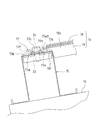
- 9 (a) and 9 (b) are partially enlarged cross-sectional views of the solar cell panel.
- the solar cell panel 18 is formed so that the plate thickness t1 of the light-receiving surface glass 18b is thinner than the plate thickness t2 of the back glass 18c (t1 ⁇ t2). That is, in this embodiment, the support member 19 is disposed on the back glass 18c.
- the support member 19 plays a role of reinforcing the back glass 18c in addition to the role as a fixture to the gantry 10. Therefore, even if the thickness of the light receiving surface glass 18b is made thinner than the thickness of the back surface glass 18c (more specifically, even if the light receiving surface glass 18b is made thinner than the conventional thickness), the strength as the solar cell panel 18 is supported. Since it is reinforced by the member 19, there is no problem. That is, according to this embodiment, it is possible to reduce the weight of the entire solar cell module 16 by thinning the light-receiving surface glass 18b while maintaining sufficient strength.
- the outer dimension of the front glass 18b and the outer dimension of the back glass 18c are formed in the same shape (that is, formed so that the end surfaces are flush).
- the outer dimension W1 of the front glass 18b may be formed to be smaller than the outer dimension W2 of the back glass 18c (W1 ⁇ W2).
- the solar battery cell 18a that photoelectrically converts sunlight is also formed in accordance with the size of the surface glass 18b.
- the solar cell module 16 is placed side by side on the gantry 10 by forming the outer dimension of the thin surface glass 18b equal to or smaller than the outer dimension of the thick back glass 18c.
- the end of the solar cell panel 18 of the next solar cell module 16 to be mounted next to the mounting bracket for fixing to the gantry 10 may hit the end of the thick back glass 18c.
- the attachment of the solar cell panel 18 to the gantry is less likely to hit the mounting glass or the end of the solar cell panel 18 disposed adjacent to the thin surface glass 18b (that is, low strength).
- the possibility that the surface glass 18b is damaged can be reduced.
- the light-receiving surface glass thinner, it is possible to secure the same light transmittance as white glass with high light transmittance, so it is possible to use blue glass with a low cost as the light-receiving surface glass, and manufacture of solar cell modules There is also an advantage that the cost can be reduced.
- the gantry 10 includes the concrete foundation 11, the base beam 12, the arm 13, the vertical beam 14, the horizontal beam 15, and the guide support 17 shown in FIG. 1, and further the support members shown in FIGS. 2 to 8. 19 is also used as a component of the gantry.
- Each concrete foundation 11 is formed by forming a mold on the ground and pouring concrete into the mold. Each concrete foundation 11 is arrange
- the upper surface 111 of these concrete foundations 11 is used as a horizontal foundation surface, and the base bars 12 are fixed on the foundation surface at equal intervals and in parallel. Further, the base bars 12, the arms 13, and the vertical bars 14 are fixed. , And the horizontal rails 15 are connected to assemble the gantry 10.
- the plurality of concrete foundations 11 it is also possible to apply foundations of other structures such as a solid foundation in which concrete is uniformly poured into the entire installation area of the gantry.
- FIG. 10 is a perspective view showing the base bar 12.
- the base bar 12 has a long main plate 12b, a pair of side plates 12a bent on both sides of the main plate 12b, and a flange 12c bent outward on one side of each side plate 12a.
- the cross-sectional shape is generally a hat shape.
- Respective elongated holes 12d are formed in the vicinity of both ends of the main plate 12b of the base bar 12, and respective perforations 12e are formed at both ends of each side plate 12a.
- FIG. 11 is a perspective view showing the arm 13.
- the arm 13 has a long main plate 13b, a pair of side plates 13a bent on both sides of the main plate 13b, and a flange 13c bent outward on one side of each side plate 13a.
- the cross-sectional shape is generally a hat shape.
- Respective perforations 13 d are formed at both ends of each side plate 13 a of the arm 13.
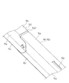
- the vertical rail 14 has a long main plate 14b, a pair of side plates 14a bent on both sides of the main plate 14b, and a flange 14c bent outward on one side of each side plate 14a.
- the cross-sectional shape is generally a hat shape.
- a pair of T-shaped holes 14d are formed in the vicinity of both ends and the center of the main plate 14b of the vertical beam 14, respectively.
- the respective perforations 14e are formed at the front end portions of the respective side plates 14a, and the respective perforations 14e are also formed at portions near the rear end portion from the central portion of each side plate 14a.
- FIGS. 13A, 13B, and 14 show crosspiece members constituting the crosspiece 15.
- FIG. 1 the horizontal rail 15 needs to be formed extremely long in the X direction, and thus it is difficult to manufacture the horizontal rail 15 as a single member. Therefore, the horizontal beam 15 is configured by connecting a plurality of beam members.
- FIGS. 13A and 13B are a perspective view and a plan view showing the first crosspiece member 151 when the rightmost crosspiece member 151 of the horizontal crosspiece 15 in FIG.
- the first crosspiece member 151 has an elongated main plate 15b, a pair of side plates 15a bent on both sides of the main plate 15b, and one side of each side plate 15a outward.
- Each of the folds 15c is bent, and its cross-sectional shape is generally a hat shape.
- T-shaped holes 15d are formed along the longitudinal direction at six locations on the center line along the longitudinal direction of the main plate 15b of the crosspiece member 151, respectively.
- a plurality of perforations 15f are formed at a plurality of locations on each side plate 15a, and respective elongated holes 15g are formed at both ends of each flange 15c.
- the length of the crosspiece member 151 is formed slightly longer than the interval between the vertical crosspieces 14 shown in FIG. 1, and the crosspiece member 151 can be bridged between the vertical crosspieces 14.
- FIG. 14 is a perspective view showing the second and subsequent beam members 152 on the left side of the first, assuming that the rightmost beam member 151 is the first in FIG.
- the second and subsequent crosspiece members 152 are also formed from the long main plate 15b, the pair of side plates 15a, and the flanges 15c, similarly to the crosspiece member 151 of FIGS. 13 (a) and 13 (b). And has a hat-shaped cross-sectional shape.
- T-shaped holes 15d along the longitudinal direction are formed at six locations on the center line along the longitudinal direction of the main plate 15b, and perforations 15f are formed at a plurality of locations on each side plate 15a.
- Each elongated hole 15g is formed.
- the length of the crosspiece member 152 is substantially the same as the interval between the vertical crosspieces 14 shown in FIG. 1 and is slightly shorter than the crosspiece member 151.
- each of the base beam 12, the arm 13, the vertical beam 14, and the horizontal beam 15 is composed of a main plate, side plates bent on both sides of the main plate, and respective ridges bent outward on one side of each side plate. It has a hat-shaped cross-sectional shape. Moreover, all hat-shaped cross-sectional shapes are the same size. Furthermore, all of them are formed by cutting or punching a plated steel plate having the same thickness and then bending the plated steel plate. For this reason, the material and the processing apparatus can be shared, and the cost can be significantly reduced.
- FIGS. 15A and 15B are a perspective view and a front view showing a triangular structure composed of a base beam 12, an arm 13, and a vertical beam 14, respectively.
- the base beam 12 is fixed to the upper surface 111 of the concrete foundation 11
- the arm 13 is connected to the rear end portion 121 of the base beam 12, and the base beam 12 is erected.
- the vertical beam 14 By connecting the vertical beam 14 obliquely between the front end portion 122 and the upper end portion 131 of the arm 13 and fixing it, a triangular structure including the base beam 12, the arm 13, and the vertical beam 14 is constructed.
- two bolts 21 are projected in advance on the upper surface 111 of the concrete foundation 11 so that the main plate 12b of the base beam 12 becomes the lower surface, and each elongated hole 12d of the main plate 12b of the base beam 12 is formed.
- the main plate 12 b is placed on the upper surface 111 of the concrete foundation 11 by being inserted through these bolts 21.
- the base rail 12 can be moved along each elongated hole 12d (moving in the Y direction in FIG. 1) using the bolt 21 as a guide pin. Adjust the position of the direction.
- the holes formed in the reinforcing bracket 22 are passed through the respective bolts 21, and the reinforcing brackets 22 are arranged inside the base rail 12. To do. Then, each nut 21 is screwed and tightened, whereby the base bar 12 is fixed to the upper surface 111 of the concrete foundation 11.
- the arm 13 is connected to the rear end 121 of the base bar 12 and is erected.
- the lower end portions of the side plates 13a are elastically deformed so as to approach each other, and the lower end portions of the side plates 13a are inserted into the rear end portions of the side plates 12a of the base bar 12 so as to hold the arms 13 independently.
- the pipe 25 is inserted between the side plates 13 a of the arm 13, the pipe 25, the perforations 13 d of the side plates 13 a of the arm 13, and the base rail 12.
- the perforation 12e of the side plate 12a is aligned, and in this state, the bolt 26 is passed through the pipe 25, the perforation 13d of each side plate 13a of the arm 13, the perforation 12e of each side plate 12a of the base bar 12, and the washer.
- the nuts 27 By screwing and tightening the nuts 27, the lower ends of the side plates 13 a of the arm 13 are connected to the side plates 12 a of the base bar 12.
- the vertical beam 14 is slanted and fixed between the front end portion 122 of the base beam 12 and the upper end portion 131 of the arm 13.
- the front end portions of the side plates 12a of the base crosspiece 12 are elastically deformed so as to approach each other, and the front end portions of the side plates 12a of the base crosspiece 12 are inserted inside the front end portions of the side plates 14a of the vertical crosspieces 14.
- each side plate 14 a of the vertical beam 14 is attached to the base beam 12 using pipes, bolts, washers, and nuts. It connects to the front-end
- the upper end portions 131 of the side plates 13a of the arm 13 are elastically deformed so as to approach each other, and the upper end portions 131 of the side plates 13a of the arm 13 are inserted inside the side plates 14a of the vertical beam 14.
- the upper end part 131 of the arm 13 is connected to each side plate 14a of the vertical beam 14 using a pipe, a volt
- a triangular structure comprising the base beam 12, the arm 13, and the vertical beam 14 is constructed.
- This triangular structure can sufficiently withstand both the vertical and horizontal forces without particularly increasing the number of parts.
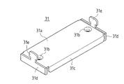
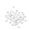
- FIG. 17 is a perspective view showing the mounting bracket 31 used for connecting and fixing the crosspiece members 151 and 152 of the horizontal crosspiece 15 to the vertical crosspiece 14.
- the mounting bracket 31 includes a rectangular main plate 31a, side plates 31c bent on both sides of the long side of the main plate 31a, and U folded back and forth on the short side of the main plate 31a.
- Each side plate 31d has a letter shape, and each T-shaped support piece 31e protrudes from the center in the short side direction of each side plate 31d.
- two screw holes 31b are formed in the main plate 31a.
- a pair of T-shaped holes 14 d arranged along the longitudinal direction are formed in the vicinity of both ends of the main plate 14 b of the vertical rail 14 and in the central portion, respectively.
- the mounting brackets 31 are respectively disposed at the central portion of the main plate 14b of the vertical beam 14 and at three locations near both ends.
- each support piece 31e of the mounting bracket 31 has a head that extends in a T-shape. Therefore, this head is inserted from below into the slit 14g of each T-shaped hole 14d formed in the main plate 14b of the vertical rail 14, and in this state, each support piece 31e is engaged with the engagement hole 14h of each T-shaped hole 14d. Is moved to the tip end side (moving in the Y1 direction in FIG. 17), and the head of each support piece 31e is hooked into the engagement hole 14h of each T-shaped hole 14d, whereby the mounting bracket 31 is attached to the vertical rail 14 The main plate 14b is attached.
- the beam members 151 and 152 are placed on the main plate 14 b of the vertical beam 14 so as to be orthogonal to the vertical beam 14, and the flanges 15 c of the beam members 151 and 152 are attached to the mounting bracket 31. It arrange
- the members 151 and 152 are screwed into the screw holes 31b of the mounting bracket 31 via the long holes 15g of the flanges 15c and the T-shaped holes 14d of the main plate 14b of the vertical rail 14 to be temporarily fixed.
- the bolts 32 can be moved along the long holes 15g of the flanges 15c of the crosspieces 151 and 152. Therefore, the crosspieces 151 and 152 are moved along the long holes 15g. (Moving in the X direction in FIG. 1) to adjust the position in the X direction.
- the mounting bracket 31 can be moved along each T-shaped hole 14d of the main plate 14b of the vertical beam 14 (in the longitudinal direction of the vertical beam 14), and the beam members 151 and 152 are also moved together with the mounting bracket 31. Can do.
- the distance between the three horizontal rails 15 arranged on the vertical rail 14 is adjusted by the movement of the rail members 151 and 152 in the longitudinal direction of the vertical rail 14.
- connection structure of the plurality of crosspiece members 151 and 152 constituting the horizontal crosspiece 15 will be described.
- the crosspiece member 151 shown in FIG. 13 is the first rightmost crosspiece member of the horizontal crosspiece 15 in FIG. 1 and is bridged between the first and second vertical crosspieces 14 of the concrete foundation 11 in FIG. It is fixed to these vertical bars 14 using mounting brackets 31.
- a crosspiece member 152 shown in FIG. 14 is a second or subsequent crosspiece member of the horizontal crosspiece 15 in FIG. 1, and is bridged between the left end portion of the next front crosspiece member and the next vertical crosspiece 14. Passed.
- the second beam member 152 is bridged between the left end of the first beam member 151 and the third vertical beam 14, and the third beam member 152 is placed on the left side of the second beam member 152.
- the n-th beam member 152 is bridged between the end and the fourth vertical beam 14, and the n-th beam member 152 is between the left end of the (n ⁇ 1) -th beam member 152 and the (n + 1) -th vertical beam 14. It is passed over to.
- the second and subsequent crosspiece members 152 are also fixed to the vertical crosspieces 14 using the mounting bracket 31.
- each side plate 15a of the first crosspiece 151 is inserted and sandwiched inside the one end 1521 of each side plate 15a of the second crosspiece 152, as shown in FIG.
- each side plate 15a of the second beam member 152 is connected to each side plate 15a of the first beam member 151 using pipes, bolts, washers, and nuts. To do.
- each side plate 15a of the (n-1) th cross member 152 is inserted and sandwiched inside one end of each side plate 15a of the nth cross member 152, and the arm 13 shown in FIG.
- the nth side plates 15a are connected to the (n-1) th side plates 15a using pipes, bolts, washers, and nuts.
- one long horizontal beam 15 is configured by connecting a plurality of beam members 151 and 152.
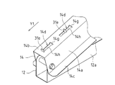
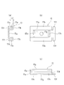
- FIG. 21 is a perspective view showing the guide support 17.
- 22A, 22B, and 22C are a front view, a plan view, and a side view showing the guide support tool 17, respectively.
- the guide support 17 includes a rectangular main plate 17a and both side portions in the longitudinal direction of the main plate 17a on the upper side, outer side, and lower side, respectively. And side portions 17b which are sequentially bent.
- the inner side of the side portion 17b is a fitting groove 17d, and the side portion bent downward of the fitting groove 17d is a hook portion 17e.
- Each fitting groove 17d is open at one end in the longitudinal direction, and is provided with a stopper 17f at the other end.
- the stopper 17f is formed by extending one end portion of the main plate 17a in the longitudinal direction along the fitting groove 17d, and further extending from both sides of the extended main plate 17a in a direction perpendicular to the fitting groove 17d. Yes. Further, a perforation 17g is formed at the center of the main plate 17a, and slits 17h are formed on both sides of the perforation 17g.
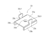
- FIG. 23 is a perspective view showing a mounting bracket 33 used to fix the guide support 17 to the cross rail 15.
- the mounting bracket 33 includes a substantially rectangular main plate 33a, U-shaped side plates 33b folded back on both sides of the main plate 33a, and center portions in the longitudinal direction of the side plates 33b, respectively.
- Each of the protruding T-shaped support pieces 33c is provided.
- a screw hole 33d is formed in the central portion of the main plate 33a.
- T-shaped holes 15 d are respectively formed at six locations along the longitudinal direction of the main plate 15 b of the crosspiece members 151, 152 that become the horizontal crosspiece 15. It is attached to each T-shaped hole 15d formed in the main plate 15b.
- each support piece 33c is inserted into the T-shaped hole 15d while the head 33c1 of each support piece 33c of the mounting bracket 33 is sequentially inserted from below into the slit 15h of the T-shaped hole 15d of the main plate 15b of the horizontal rail 15. Is moved to the side of the engagement hole 15i (moved in the X1 direction in FIG. 23), and the head 33c1 of each support piece 33c is hooked on the engagement hole 15i of the T-shaped hole 15d. It is attached to 15 main plates 15b.
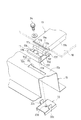
- FIG. 25 and 26 are a perspective view and a sectional view showing a fixing structure of the guide support 17 using the mounting bracket 33.
- FIG. FIG. 27 is an exploded perspective view showing a fixing structure of the guide support 17 using the mounting bracket 33.
- the head 33c1 of each support piece 33c of the mounting bracket 33 is hooked on the T-shaped hole 15d of the main plate 15b of the horizontal rail 15, and the head 33c1 of each support piece 33c is attached.
- the guide support 17 is disposed on the main plate 15 b of the horizontal beam 15 by projecting onto the main plate 15 b of the horizontal beam 15 and inserting the heads 33 c 1 of the support pieces 33 c into the slits 17 h of the guide support 17.
- the perforations 17g of the guide support 17 are overlapped with the screw holes 33d of the mounting bracket 33 through the T-shaped holes 15d of the horizontal rail 15, and the bolts 34 are perforated 17g of the guide support 17 and the T-shaped holes of the horizontal rail 15. It is screwed into the screw hole 33d of the mounting bracket 33 through 15d and tightened. As a result, the guide support 17 is fixed on the main plate 15b of the cross rail 15.
- each concrete foundation 11 is laid, and a triangular structure including a base beam 12, an arm 13, and a vertical beam 14 is formed on each concrete foundation 11, and three horizontal beams 15 are formed on each vertical beam 14.
- a plurality of guide supports 17 are fixed on the horizontal rails 15 at intervals.
- the fitting grooves 17d on both sides of the guide support 17 are arranged in parallel with the horizontal rails 15, and the hooking portions 17e (see FIG. 21) of the fitting grooves 17d A gap is formed between the main plate 15 b of the crosspiece 15. Then, the engaging portion 19e of the support member 19 of the solar cell module 16 enters the fitting groove 17d through the gap between the hooking portion 17e of the fitting groove 17d and the main plate 15b of the horizontal rail 15, and the engagement of the supporting member 19 is performed. The portion 19e is fitted (engaged) in the fitting groove 17d.
- the side plate 19b of the support member 19 contacts the stopper 17f of the guide support 17, and the contact portion 19f of the support member 19 contacts the main plate 15b of the horizontal beam 15 and the side plate 15a (the corner of the horizontal beam 15). Yes.
- the engagement portion 19e of the support member 19 is fitted into the fitting groove 17d of the guide support 17 so that the end portion along the longitudinal direction of the support member 19 is supported.
- the end portion is supported on the main plate 15 b of the horizontal rail 15.
- the side plate 19b of the support member 19 comes into contact with the stopper 17f of the guide support 17 and the contact portion 19f of the support member 19 comes into contact with the corner portion of the horizontal rail 15 so that the solar cell module 16 is positioned.
- the contact portion 19f of the side plate 19b of the support member 19 is in contact with the two sides of the main plate 15a and the side plate 15b at the corner of the crosspiece 15 so that the longitudinal direction of the support member 19 (in FIG. (Y direction) can be reliably regulated, and the engagement portion 19e of the support member 19 is fitted in the fitting groove 17d of the guide support 17 so that the movement in the direction perpendicular to the mounting surface of the gantry 10 is achieved. Can be controlled.
- the side plate 19b of the support member 19 abuts against the stopper 17f of the guide support 17 so that the support member 19 is prevented from sliding (sliding in the X direction in FIG. 1), and the solar cell module 16 is also prevented from sliding. .
- each guide support 17 on the crosspiece 15 is common in each of the crosspieces 15, and the first guide supporter on each crosspiece 15. 17 are arranged on a straight line in the Y direction, the second guide support 17 on each horizontal beam 15 is arranged on a straight line in the Y direction, and thereafter the nth guide support 17 on each horizontal beam 15 is similarly arranged. Line up on a straight line in the Y direction.
- the pitch of the first and second guide supports 17 is set to be the same as the pitch of the two support members 19 of the solar cell module 16, and the pitch of the third and fourth guide supports 17 is the solar cell module.
- each guide support 17 is positioned in each of the cross rails 15 so that the ends of the two support members 19 of the solar cell module 16 can be supported by the odd-numbered and even-numbered guide support 17. Has been.
- the pitches of the second and third guide supports 17 are arranged so that the pitches of the fourth and fifth guide supports 17, that is, the odd and even guide supports 17 are adjacent to each other.
- the pitch of the support members 19 of the two solar cell modules 16 is set to be approximately the same or slightly wider. Thereby, it is possible to arrange the solar cell modules 16 side by side with almost no gap between the two adjacent solar cell modules 16.
- the protruding end portion of the support member 19 of the solar cell module 16 is provided.
- the protruding end of the support member 19 of the solar cell module 16 is placed on the main plate 15b of the horizontal rail 15 in a state where it is shifted laterally (in the X direction) from the guide support 17 of the horizontal rail 15.
- the contact portion 19 f of the support member 19 is brought into contact with the main plate 15 b and the side plate 15 a (corner portion of the horizontal beam 15) of the horizontal beam 15.
- the engaging portion 19e of the support member 19 is positioned with respect to the corner portion of the horizontal rail 15, and when viewed from the X direction, the engaging portion 19e of the support member 19 is fitted into the fitting groove of the guide support member 17. It overlaps 17d.
- the solar cell module 16 is slid in the X direction (right direction in the figure), and the contact portion 19f of the support member 19 is moved to the main plate 15b and the side plate 15a of the cross rail 15.
- the engagement portion 19e of the support member 19 enters from the opened end of the fitting groove 17d of the guide support device 17, and the engagement portion 19e of the support member 19 is fitted to the guide support device 17. It fits in the mating groove 17d.
- the engaging portion 19e of the support member 19 is brought into contact with the stopper 17f provided at the other end of the fitting groove 17d of the guide support member 17. Abut.
- the end of the solar cell module 16 is supported on the main plate 15b of the cross rail 15. Further, the side plate 19 b of the support member 19 contacts the stopper 17 f of the guide support 17, and the contact portion 19 f of the support member 19 contacts the corner portion of the horizontal rail 15, so that the solar cell module 16 is positioned. Further, the contact of the side plate 19b of the support member 19 with the stopper 17f of the guide support 17 prevents the support member 19 from sliding (sliding in the descending order of the arrangement of the solar cell modules 16). Sliding in the descending direction is also prevented.
- the first and second guides of each horizontal beam 15 are connected to both ends of each support member 19 of the rightmost first solar cell module 16.
- the both ends of each support member 19 of the solar cell module 16 are placed on each horizontal rail 15 by shifting from the support 17.
- the abutting portions 19 f of the support members 19 in the downwardly inclined direction of the solar cell module 16 abut on the corners of the lower horizontal rail 15.
- the engaging portion 19e in the downwardly inclined direction of each support member 19 overlaps the fitting groove 17d of the guide support 17 of the lower horizontal rail 15.
- the interval between the horizontal beams 15 is set in advance so that the distance between the fitting grooves 17d of the guide support 17 on each horizontal beam 15 is the same as the distance between the engaging portions 19e at both ends of the support member 19. It has been adjusted.
- This adjustment can be performed when the horizontal rail 15 is fixed by the mounting bracket 31 as described above.
- the contact portion 19f of each support member 19 in the downward inclination direction of the solar cell module 16 contacts the corner portion of the lower horizontal rail 15, the inclination of each support member 19 when viewed from the X direction.
- the engaging portion 19e at the other end in the upward direction also overlaps with the fitting groove 17d of the guide support 17 of the central cross rail 15.
- the solar cell module 16 is slid in the X direction, and the engaging portions 19 e at both ends of each support member 19 are fitted to the guide support 17 of each horizontal rail 15.
- the both ends of the solar cell module 16 are supported in a state of being laid over the horizontal rails 15 by being inserted into the grooves 17d, fitted and brought into contact with the stoppers 17f.
- each support member 19 of the second solar cell module 16 is inserted into the fitting grooves 17d of the guide support 17 of each horizontal rail 15 to be fitted and stopped.
- the both end portions of the solar cell module 16 are supported on the horizontal rails 15 so as to abut on the 17f.
- the third, fourth,... Solar cell modules 16 are supported across the horizontal rails 15, and the lower first row is interposed between the lower horizontal rail 15 and the central horizontal rail 15.
- the solar cell modules 16 are arranged side by side.
- both end portions of the support members 19 of the rightmost first solar cell module 16 are placed on the main plate 15 b of each horizontal beam 15.
- the engaging portions 19e at both ends of each support member 19 of the solar cell module 16 are fitted into the fitting grooves 17d of the guide support 17 of each horizontal rail 15, and both end portions of the solar cell module 16 are fitted.
- the second, third,... Solar cell modules 16 are also supported by being supported over each horizontal beam 15 in the same order, and the upper 2 between the central horizontal beam 15 and the upper horizontal beam 15.
- the solar cell modules 16 in the row are arranged side by side.
- each guide support 17 on the central crosspiece 15 supports both the solar cell modules 16 in the lower first row and the solar cell modules 16 in the upper second row.
- Each fitting groove 17d on both sides of each guide support 17 faces each solar cell module 16 in the lower first row and each solar cell module 16 in the upper second row, and one side of each guide support 17
- the fitting groove 17d is fitted with the engaging portion 19e at the end in the inclined upper direction of each support member 19 in the lower first row, and is fitted into the fitting groove 17d on the other side of each guide support member 17.
- the engaging portions 19e at the ends of the respective support members 19 in the inclined downward direction are fitted.
- the support members of the two solar cell modules 16 arranged so that the odd-numbered and even-numbered guide supports 17 are adjacent to each other in pitch. Since the pitch is set to be substantially the same as or slightly wider than 19 pitches, the solar cell modules 16 are arranged side by side with almost no gap between the two adjacent solar cell modules 16.
- the last order guide support 17 on the cross rail 15 is once removed, and the left and right sides of the guide support 17 are reversed.
- the guide support 17 is fixed again on the horizontal rail 15, and the engaging portion 19 e of the support member 19 is fitted into the fitting groove 17 d of the guide support 17 to support the end of the support member 19.
- the side plate 19b of the support member 19 is brought into contact with the stopper 17f of the guide support 17 to prevent the support member 19 from sliding.
- the left and right of the guide support 17 are reversed, this is prevented.
- the sliding direction becomes the ascending order of the arrangement of the solar cell modules 16. Thereby, the slide to the ascending order of the solar cell module 16 of the last order is blocked
- the right and left of the last order guide support 17 are reversed and fixed, and the last order solar cell module 16 is prevented from sliding in the ascending order.
- the solar cell modules 16 are arranged side by side without any gap as described above. Sliding to is prevented. For this reason, in any of the solar cell modules 16, the solar cell module 16 cannot be slid in the ascending order, and the engaging portion 19 e of the support member 19 cannot be removed from the fitting groove 17 d of the guide support 17. The solar cell module 16 cannot be removed. Of course, since the slides of the solar cell modules 16 in the descending order are prevented by the stoppers 17f of the guide support members 17 in the order before the last order, the solar cell modules 16 are also slid in the descending direction. I can't.
- each guide support 17 on the horizontal rails 15 is temporarily removed, and the left and right sides of the respective guide support 17 are reversed.
- each guide support 17 is fixed again on each crosspiece 15 and the end of each support member 19 is supported by each guide support 17 in the ascending order of the solar cell modules 16 in the last order. If the sliding is prevented, each solar cell module 16 cannot be removed, and each solar cell module 16 cannot be slid in either the ascending order or the descending order.
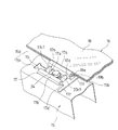
- the solar cell module 16 is prevented from sliding in the ascending direction (left direction in the figure), and the engagement portion 19 e of the support member 19 once fitted is guided and supported.
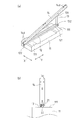
- a pin insertion hole 15m is formed in the main plate 15d in the vicinity of the position where the slit 15h of the T-shaped hole 15d is formed.
- the engaging portion 19e of the support member 19 of the solar cell module 16 is fitted into the fitting groove 17d of the guide support 17, and is further slid in the descending direction (right direction in the figure), so that the side plate of the support member 19 In a state where 19b is brought into contact with the stopper 17f of the fitting groove 17d, a pin 37 for preventing removal is inserted into the pin insertion hole 15m.
- the pin insertion hole 15m is provided on the slide line S when the engaging portion 19e of the support member 19 slides in the X direction on the main plate 15b of the horizontal beam 15 on the main plate 15b of the horizontal beam 15. Therefore, by inserting the pin 37 for preventing slipping into the pin insertion hole 15m, the head portion 37a of the pin 37 prevents the engaging portion 19e of the support member 19 from sliding in the ascending direction, and is once fitted. It is possible to prevent the engaging portion 19e of the supported support member 19 from coming off from the fitting groove 17d of the guide support 17.
- the solar cell modules 16 arranged in parallel across the horizontal rails 15 can be configured to individually prevent sliding movement in both ascending and descending directions after installation.
- both the ascending direction and the descending direction after the installation of the individual solar cell modules 16 arranged across the horizontal beam 15 are arranged. Since the sliding movement can be prevented for each solar cell module 16, the installation work can be performed smoothly.
- all the solar cell modules 16 are prevented from sliding in both the ascending and descending directions, so that the pin 37 is inserted into the pin insertion hole 15m at this time. You may make it extract from.
- the pin 37 may have a simple screw structure and may be screwed and fixed to the pin insertion hole 15m, or may simply be inserted.
- the guide support 17 is fixed to the horizontal rail 15 by the mounting bracket 33 and the bolt 34, and the guide support 17 can be removed by removing the bolt 34. Therefore, each support member 19 of the solar cell module 16 is provided.
- the solar cell module 16 can be removed by removing the four guide supports 17 that support the both end portions. For this reason, when the maintenance or replacement of any solar cell module 16 becomes necessary, only the arbitrary solar cell module 16 can be removed. At this time, if the pin 37 is inserted into the pin insertion hole 15m, the adjacent solar cell module 16 does not slide, so that maintenance or replacement work can be performed smoothly.
- each solar cell module 16 for each solar cell module 16, the solar cell module 16 is laid over each horizontal rail 15, the solar cell module 16 is slid, and both ends of each support member 19 of the solar cell module 16 are moved.
- the plurality of solar cell modules 16 are connected to each horizontal beam 15. It can be installed side by side.
- each support member 19 in the downwardly inclined direction of the solar cell module 16 is in contact with the corner portion of the lower horizontal rail 15, the solar cell module 16 does not slide down, Safety is ensured.
- each guide support 17 is fixed on the horizontal beam 15 before shipment from the factory, there is almost no need to use a tool in the operation of installing each solar cell module 16 across the horizontal beam 15. , Work efficiency can be improved.
- the fitting grooves 17d are provided on both sides of the guide support member 17, the solar cell modules 16 in the lower first row and the upper second row are provided by the guide support members 17 on the central cross rail 15. Any of the solar cell modules 16 can be supported. Further, since the respective stoppers 17f are provided in the respective fitting grooves 17d, when the guide support 17 is fixed on the cross rail 15 again after the left and right sides of the guide support 17 are reversed, the guide support 17 The sliding direction of the solar cell module 16 blocked by the stopper 17f can be reversed.
- any solar cell module 16 can be removed by removing the guide support 17, and maintenance or replacement of the optional solar cell module 16 is easily performed. be able to.
- a T-shaped hole 15 d of the horizontal beam 15 is formed on the center line in the longitudinal direction of the main plate 15 b of the horizontal beam 15, as is clear from FIG.
- the main plate 15b is fixed on the center line.
- the force due to wind pressure or snow load does not act accurately on the center line of the horizontal rail 15.
- the force of the load of wind or snow is disengaged from the center line of the horizontal rail 15 to fit the guide support portion 17. Since the groove 17d (and the engaging portion 19e of each support member 19) receives the force, the force acts between the fitting groove 17d (and the engaging portion 19e) and the bolt 34. For this reason, even if the force acts slightly deviating from the center line of the horizontal rail 15 and thus the force that twists the horizontal rail 15 can be suppressed, it cannot be said that the force is not generated at all.
- each support member 19 of the solar cell panel 16 since the contact portions 19f formed at both ends of each support member 19 of the solar cell panel 16 are in contact with the corners of each horizontal rail 15, the both ends of each support member 19 are The abutting portion 19f acts to suppress such a force that twists each of the horizontal rails 15. Accordingly, each support member 19 functions to reinforce each crosspiece 15 or the frame.
- each support member 19 is used not only as a component of the solar cell module 16 but also as a component of the gantry. Thereby, the number of parts and cost of the solar power generation system can be greatly reduced.
- the strength of the solar cell panel 18 is substantially equivalent to the strength of a thin glass plate as compared to the area thereof. Therefore, when a force due to wind or snow load is applied to the solar cell panel 18, the solar cell panel 18 May be bent and cracked, and this must be prevented.
- a frame is provided so as to surround four sides of the solar cell panel to form a solar cell module, and the solar cell panel is prevented from bending and cracking by the drag of this frame.
- the method of making the area of the solar cell panel per sheet small and reducing the bending force concerning a solar cell panel was taken.
- the two support members 19 exert a resistance against the force to bend the solar cell panel 18 around the virtual axis in the X direction (shown in FIG. 1). Since each horizontal beam 15 supporting both ends of the two support members 19 exerts a resistance against the force to bend the battery panel 18 around the virtual axis in the Y direction (shown in FIG. 1). The solar cell panel 18 is not greatly bent and cracked.
- each support member 19 is not only a component of the solar cell module 16 but also plays a part of the role of a mount on which the solar cell module 16 is installed.
- each support member 19 has a function in which the abutting portions 19f formed at both ends abut against the corners of the horizontal rails 15 and hold down the force that twists the horizontal rails 15 and the horizontal rails 15.
- it since it has a function of preventing the solar cell panel 18 from being bent and cracked, it is not only a component of the solar cell module 16 but also a component of the gantry.
- both end portions of each support member 19 of the solar cell module 16 are supported across the horizontal rails 15, and each row of solar cells above and below the central horizontal rail 15. Since the modules 16 can be supported, the number of the horizontal rails 15 can be suppressed to the number of rows of the solar cell modules 16, and the number of parts, construction man-hours, and cost of the solar power generation system can be further reduced. It becomes.
- the height of the engaging portion 19e of the support member 19 (the height L1 in FIGS. 6B and 8B) and the height of the hook portion 17e of the fitting groove 17d of the guide support 17 (FIG. 22).
- the height L2) of (a) is set low. For this reason, even if the force which pulls out the engaging part 19e of the support member 19 from the fitting groove 17d of the guide support 17 acts, it is hard to deform
- the support strength between the engagement portion 19e of the support member 19 and the fitting groove 17d of the guide support 17 is high.
- the end of the support member 19 is once bent downward and then folded upward to form an engaging portion 19e below the upper surface of the main plate 19a of the support member 19,
- the end 18a of the solar cell panel 18 on the main plate 19a may be pushed out above the guide support 17 so that at least a part of the guide support 17 is covered by the end 18a of the solar cell panel 18.
- the guide support 17 is hardly exposed and a preferable appearance is obtained.
- the ratio of the occupied area of the solar cell panel 18 to the installation area of the solar power generation system can be increased to improve the power generation efficiency.
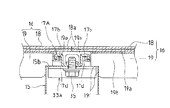
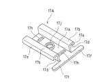
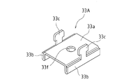
- the bolt 35 may be removed from below using a guide support 17A as shown in FIG. 36 and a mounting bracket 33A as shown in FIG.
- a guide support 17A shown in FIG. 36 is provided with a screw hole 17j in the main plate 17a instead of providing the main plate 17a with a hole 17g like the guide support 17 in FIG.
- the mounting bracket 33A shown in FIG. 37 is provided with a hole 33f in the main plate 33a instead of the screw hole 33d in the main plate 33a like the mounting bracket 33 in FIG.
- the heads of the support pieces 33c of the mounting bracket 33A are protruded on the main plate 15b of the horizontal rail 15, and the heads of the support pieces 33c are inserted into the slits 17h of the guide support 17A.
- the guide support 17A is disposed on the main plate 15b of the horizontal beam 15, the screw hole 17j of the guide support 17A is overlapped with the hole 33f of the mounting bracket 33A via the T-shaped hole 15d of the horizontal beam 15, and the bolt 35 is Insert the bolt 35 from below the main plate 15b of the crosspiece 15 and screw it into the screw hole 17j of the guide support 17A through the hole 33f of the mounting bracket 33A and the T-shaped hole 15d of the horizontal crosspiece 15 to tighten the guide support 17A.
- the bolt 35 It is fixed on the main plate 15b of the horizontal rail 15. In this case, the bolt 35 can be easily removed from the lower side of the main plate 15b of the horizontal rail 15. In addition, the operator does not need to get on the solar cell module 16 for the tightening operation of the bolt 35, and the safety of the operation is improved.
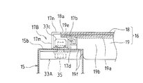
- the end 18 a of the solar cell panel 18 of the solar cell module 16 is pushed out above the guide support 17, and the solar cell panel 18. Even if half of the guide support 17 is covered by the end portion 18a, the bolt 34 is exposed. Therefore, as shown in FIG. 38, the bolts 35 may be covered using a guide support 17B.
- the guide support 17B is provided with a side portion 17b and a fitting groove 17d on one side of the main plate 17a, a side plate 17m and a cover plate 17n on the other side of the main plate 17a, and a screw hole in the main plate 17a. 17j and slits 17h are formed.
- the heads of the support pieces 33c of the mounting bracket 33A are projected on the main plate 15b of the cross rail 15, and the heads of the support pieces 33c are inserted into the slits 17h of the guide support 17B.
- the guide support 17B is disposed on the main plate 15b of the horizontal beam 15, the bolt 35 is inserted from below the main plate 15b of the horizontal beam 15, and the bolt 35 is inserted into the hole 33f of the mounting bracket 33A and the T-shaped hole 15d of the horizontal beam 15. Then, the guide support 17B is fixed on the main plate 15b of the cross rail 15 by screwing it into the screw hole 17j of the guide support 17B.
- the bolt 35 can be easily removed from the lower side of the main plate 15b of the horizontal rail 15, and the operator does not need to get on the solar cell module 16 for the tightening work of the bolt 35, thereby improving the safety of the work. To do.
- the engaging portion 19e of the support member 19 is bent upward at both longitudinal ends of the main plate 19a, as shown in FIGS. 5 and 6A, 6B, and 6C.
- the main plate 19a of the support member 19B is directly extended in the longitudinal direction as shown in FIGS. 40 (a) and 40 (b) without being bent in this way. May be the engaging portion 19m.
- the guide support 17C having the shape shown in FIGS. 41 and 42 (a), (b), (c) can be used. That is, in the guide support 17 shown in FIGS. 21 and 22 (a), 22 (b), and 22 (c), both side portions in the longitudinal direction of the main plate 17a are sequentially bent upward, outward, and downward to open downward. Although the fitting groove 17d is formed, the guide support 17C shown in FIGS. 41 and 42 (a), 42 (b), and 42 (c) sequentially has both side portions in the longitudinal direction of the main plate 17a on the upper side and the outer side, respectively. By bending, an inverted L-shaped engagement groove 17m is formed. That is, as shown in FIGS.
- the fitting grooves 17m on both sides of the guide support 17C are arranged in parallel with the horizontal rail 15, the horizontal portion 17m1 of each fitting groove 17m and the main plate 15b of the horizontal rail 15. A gap opened laterally is formed between the two.
- Other configurations are the same as those of the guide support 17 described above.
- the engagement groove 17m of the guide support 17C and the engagement portion 19m of the support member 19B are engaged with each other by the engagement portion 19m of the support member 19B.
- the horizontal portion 17m1 and the main plate 15b of the horizontal rail 15 enter the gap, and the engaging portion 19m of the support member 19 engages with the horizontal portion 17m1 of the fitting groove 17m.
- the engaging portion 19m is engaged so that the upper surface of the engaging portion 19m is in contact with the lower surface of the horizontal portion 17m1.
- the side plate 19b of the support member 19B contacts the stopper 17f of the guide support 17C, and the contact portion 19f of the support member 19B contacts the main plate 15b of the horizontal beam 15 and the side plate 15a (corner of the horizontal beam 15). Yes.
- the engaging portion 19m of the support member 19B engages with the fitting groove 17m of the guide support 17C, whereby the end portion along the longitudinal direction of the support member 19B is supported.
- the end portion is supported on the main plate 15 b of the horizontal rail 15.
- the side plate 19b of the support member 19B comes into contact with the stopper 17f of the guide support 17, and the contact portion 19f of the support member 19B comes into contact with the corner portion of the horizontal rail 15, so that the solar cell module 16 is positioned.
- the contact portion 19f of the side plate 19b of the support member 19B contacts the two sides of the main plate 15a and the side plate 15b at the corners of the crosspiece 15 so as to fit in the longitudinal direction of the support member 19B (FIG. 1).
- the engagement portion 19m of the support member 19B is engaged with the fitting groove 17m of the guide support 17C, so that it is perpendicular to the mounting surface of the gantry 10.
- Directional movement can be restricted.
- the side plate 19b of the support member 19B comes into contact with the stopper 17f of the guide support 17C, thereby preventing the support member 19B from sliding (sliding in the X direction in FIG. 1) and preventing the solar cell module 16 from sliding. .
- the stopper of the guide support tool may be separated from the guide support tool, or the guide support tool or the stopper may be fixed to the side rail so as not to be detachable.
- the present invention can be applied not only to support a solar cell module but also to other structures, and may support, for example, a reflector panel used for solar thermal power generation, thereby providing a solar thermal power generation system. It is very useful for building.
Landscapes
- Engineering & Computer Science (AREA)
- Chemical & Material Sciences (AREA)
- Life Sciences & Earth Sciences (AREA)
- Sustainable Development (AREA)
- Sustainable Energy (AREA)
- Thermal Sciences (AREA)
- Physics & Mathematics (AREA)
- Combustion & Propulsion (AREA)
- Mechanical Engineering (AREA)
- General Engineering & Computer Science (AREA)
- Architecture (AREA)
- Civil Engineering (AREA)
- Structural Engineering (AREA)
- Photovoltaic Devices (AREA)
Abstract
Description
11 コンクリート基礎
12 ベース桟
13 アーム
14 縦桟
15 横桟
16 太陽電池モジュール
17,17A,17B,17C 案内支持具
17d 嵌合溝
17e 掛部
17f ストッパー
17m 嵌合溝
17m1 水平部
18 太陽電池パネル
18a 太陽電池セル
18b 受光面ガラス
18c 裏面ガラス
19,19A,19B 支持部材
19a 主板
19b 側板
19c 底板
19d 内側板
19e,19m 係合部(被取付具)
19f 当接部
19g 切り込み片
20 両面テープ
21,26,32,34 ボルト
22 補強金具
25 パイプ
27 ナット
31,33 取付金具(取付具)
41 端子ボックス
Claims (10)
- 太陽光を光電変換する太陽電池セルを受光面ガラスと裏面ガラスとの間に介在させた合わせガラス構造の太陽電池パネルを備えた太陽電池モジュールであって、
前記裏面ガラスの表面に、長尺状の支持部材が前記太陽電池パネルの長手方向に沿って配置固定されていることを特徴とする太陽電池モジュール。 - 請求項1に記載の太陽電池モジュールであって、
前記支持部材は、前記太陽電池パネルの短手方向に間隔を空けて複数本配置されていることを特徴とする太陽電池モジュール。 - 請求項1または請求項2に記載の太陽電池モジュールであって、
前記支持部材の長手方向の端部は、前記太陽電池パネルの端部から突出して設けられていることを特徴とする太陽電池モジュール。 - 請求項1から請求項3までのいずれか1項に記載の太陽電池モジュールであって、
前記支持部材は端部に係合部を備えることを特徴とする太陽電池モジュール。 - 請求項4に記載の太陽電池モジュールであって、
前記支持部材は、長尺状の主板と、この主板の長手方向に沿う両側から下方に折り曲げられた側板と、前記主板の長手方向の両端部でそれぞれ上方に折り曲げられた係合部と、を備えていることを特徴とする太陽電池モジュール。 - 請求項4に記載の太陽電池モジュールであって、
前記支持部材は、長尺状の主板と、この主板の長手方向に沿う両側部から下方に折り曲げられた側板と、各側板の下端部から内側に折り曲げられた底板と、各底板の対向する内側端部から上方に折り曲げられた内側板と、前記主板の長手方向の両端部でそれぞれ上方に折り曲げられた係合部と、を備えていることを特徴とする太陽電池モジュール。 - 請求項5または請求項6に記載の太陽電池モジュールであって、
前記側板の長手方向の両端部の一部がそれぞれL字状に切り欠かれていることを特徴とする太陽電池モジュール。 - 請求項1から請求項7までのいずれか1項に記載の太陽電池モジュールであって、
前記支持部材は、クッション部材の両面に粘着剤層を有する両面テープによって前記太陽電池パネルの裏面ガラスに接着固定されていることを特徴とする太陽電池モジュール。 - 請求項1から請求項8までのいずれか1項に記載の太陽電池モジュールであって、
前記受光面ガラスの板厚は、前記裏面ガラスの板厚より薄く形成されていることを特徴とする太陽電池モジュール。 - 請求項9に記載の太陽電池モジュールであって、
前記表面ガラスの外形寸法が、前記裏面ガラスの外形寸法よりも小さいか、若しくは同一形状に形成されていることを特徴とする太陽電池モジュール。
Priority Applications (4)
| Application Number | Priority Date | Filing Date | Title |
|---|---|---|---|
| AU2011230437A AU2011230437A1 (en) | 2010-03-25 | 2011-03-22 | Solar cell module |
| EP11759364.0A EP2551918A4 (en) | 2010-03-25 | 2011-03-22 | SOLAR CELL MODULE |
| CN2011800150569A CN102812560A (zh) | 2010-03-25 | 2011-03-22 | 太阳能电池组件 |
| US13/577,556 US20120312356A1 (en) | 2010-03-25 | 2011-03-22 | Solar cell module |
Applications Claiming Priority (4)
| Application Number | Priority Date | Filing Date | Title |
|---|---|---|---|
| JP2010-070382 | 2010-03-25 | ||
| JP2010070382 | 2010-03-25 | ||
| JP2010139788A JP5263795B2 (ja) | 2010-03-25 | 2010-06-18 | 太陽電池モジュールの取付構造 |
| JP2010-139788 | 2010-06-18 |
Publications (1)
| Publication Number | Publication Date |
|---|---|
| WO2011118559A1 true WO2011118559A1 (ja) | 2011-09-29 |
Family
ID=44673111
Family Applications (1)
| Application Number | Title | Priority Date | Filing Date |
|---|---|---|---|
| PCT/JP2011/056747 Ceased WO2011118559A1 (ja) | 2010-03-25 | 2011-03-22 | 太陽電池モジュール |
Country Status (6)
| Country | Link |
|---|---|
| US (1) | US20120312356A1 (ja) |
| EP (1) | EP2551918A4 (ja) |
| JP (1) | JP5263795B2 (ja) |
| CN (1) | CN102812560A (ja) |
| AU (1) | AU2011230437A1 (ja) |
| WO (1) | WO2011118559A1 (ja) |
Cited By (1)
| Publication number | Priority date | Publication date | Assignee | Title |
|---|---|---|---|---|
| US20150083220A1 (en) * | 2012-04-18 | 2015-03-26 | Ricard Pardell Vilella | Field-assemblable concentration photovoltaics system |
Families Citing this family (35)
| Publication number | Priority date | Publication date | Assignee | Title |
|---|---|---|---|---|
| JP5377798B2 (ja) * | 2011-05-06 | 2013-12-25 | 三菱電機株式会社 | 太陽電池システム、及び太陽電池モジュール |
| ES2753641T3 (es) * | 2011-11-30 | 2020-04-13 | Cnbm Bengbu Design & Res Institute For Glass Industry Co Ltd | Módulo solar sin marco con soporte del mismo |
| US20150000740A1 (en) * | 2012-01-17 | 2015-01-01 | Sharp Kabushiki Kaisha | Solar cell module |
| JP2013221287A (ja) * | 2012-04-16 | 2013-10-28 | Sanko Co Ltd | ソーラーパネル装置 |
| WO2013157381A1 (ja) * | 2012-04-18 | 2013-10-24 | シャープ株式会社 | 太陽電池モジュール、太陽電池モジュールの製造方法、太陽電池モジュールの支持構造、及び太陽光発電システム |
| JP6029317B2 (ja) * | 2012-04-27 | 2016-11-24 | ソーラーフロンティア株式会社 | 太陽電池モジュール |
| US20130298968A1 (en) * | 2012-05-14 | 2013-11-14 | Mika Brian Laitila | Solar panel racking system having separate support structure and cover assembly |
| JP5972049B2 (ja) * | 2012-05-25 | 2016-08-17 | 三菱電機株式会社 | 太陽電池モジュール |
| JP6181575B2 (ja) * | 2013-02-26 | 2017-08-16 | 京セラ株式会社 | 太陽電池装置 |
| US9595627B2 (en) | 2013-03-15 | 2017-03-14 | John Paul Morgan | Photovoltaic panel |
| US9714756B2 (en) | 2013-03-15 | 2017-07-25 | Morgan Solar Inc. | Illumination device |
| US9960303B2 (en) | 2013-03-15 | 2018-05-01 | Morgan Solar Inc. | Sunlight concentrating and harvesting device |
| CN105051454B (zh) | 2013-03-15 | 2019-06-18 | 摩根阳光公司 | 光板、具有改善界面的光学组件及具有改善的制造容差的光板 |
| DE102014105052A1 (de) | 2013-04-12 | 2014-10-16 | Solarwatt Gmbh | Glas-Glas-Solarmodul-Laminat mit Solarzellen |
| USD746768S1 (en) | 2013-05-15 | 2016-01-05 | Mika Brian Laitila | Solar panel rack |
| AU2014277610A1 (en) * | 2013-06-03 | 2016-01-21 | Bluescope Steel Limited | Solar roof panel |
| US20150040965A1 (en) * | 2013-08-12 | 2015-02-12 | Zep Solar Llc | Ground Mount Structure With Mounting Assemblies And Central Quick-Mount Rail |
| WO2015116911A1 (en) * | 2014-01-30 | 2015-08-06 | Sunedison Llc | Solar module with integrated collapsible rack assembly |
| JP2016067153A (ja) * | 2014-09-25 | 2016-04-28 | シャープ株式会社 | 太陽電池モジュールの設置構造、太陽電池モジュールの設置方法及び太陽光発電システム |
| KR101638111B1 (ko) * | 2014-11-21 | 2016-07-08 | 썬파크 주식회사 | 롤 블라인드 |
| US20170126169A1 (en) * | 2015-11-03 | 2017-05-04 | Gamechange Solar Llc | Grid-lite roof system for solar panel installations |
| US20170126168A1 (en) * | 2015-11-03 | 2017-05-04 | Gamechange Solar Llc | Grid-lite roof system for solar panel installations |
| US10256768B2 (en) * | 2016-04-25 | 2019-04-09 | Cmco Solar, Llc | Photovoltaic array mounting structure |
| US9923513B2 (en) * | 2016-05-13 | 2018-03-20 | Boson Robotics Ltd. | Cleaning mechanism having water spray function and photovoltaic panel cleaning equipment having same |
| CN105897128B (zh) * | 2016-05-24 | 2017-12-15 | 广东保威新能源有限公司 | 双玻光伏组件的安装挂件、固定结构及其装配方法 |
| DE102016015436B4 (de) * | 2016-12-23 | 2026-02-26 | Next2Sun Technology GmbH | Photovoltaik-Anlage mit bifazialen Photovoltaik-Modulen |
| US11431288B2 (en) | 2018-03-30 | 2022-08-30 | Sunpower Corporation | Photovoltaic module with a cross rail assembly |
| CN108923739A (zh) * | 2018-10-16 | 2018-11-30 | 苏州金山太阳能科技有限公司 | 一种太阳能跟踪器的光伏板的锚固结构 |
| US11271518B2 (en) | 2018-11-08 | 2022-03-08 | OMCO Solar, LLC | Mounting bracket for mounting photovoltaic modules to torque tube beam |
| DE102019003390A1 (de) * | 2019-05-13 | 2020-11-19 | Schletter lnternational B.V. | Längsprofil und Modulklemme für ein Montagesystem für Solarmodule sowie ein solches Montagesystem |
| AU2021231709A1 (en) * | 2020-03-02 | 2022-09-29 | Planted Solar Inc. | Solar module racking system |
| CN111192933A (zh) * | 2020-03-08 | 2020-05-22 | 上海金羊钫新能源科技中心(有限合伙) | 一种太阳能光伏组件及建筑光伏一体化组件 |
| CN112713847A (zh) * | 2020-12-28 | 2021-04-27 | 苏州腾晖光伏技术有限公司 | 高可靠性大尺寸双面组件支架系统 |
| AT18279U1 (de) * | 2023-03-31 | 2024-08-15 | Energetica Ind Gmbh | Photovoltaik-modul |
| US12665537B2 (en) * | 2024-06-03 | 2026-06-23 | Unirac, Inc. | Clamp for securing a solar panel module |
Citations (5)
| Publication number | Priority date | Publication date | Assignee | Title |
|---|---|---|---|---|
| JPH09235844A (ja) | 1996-02-29 | 1997-09-09 | Shiroki Corp | 太陽電池取付け構造 |
| JP2000077696A (ja) * | 1998-08-31 | 2000-03-14 | Ig Tech Res Inc | 太陽電池モジュール |
| JP2003343058A (ja) * | 2003-06-16 | 2003-12-03 | Sharp Corp | 太陽電池モジュールの取付構造 |
| WO2006121013A1 (ja) * | 2005-05-11 | 2006-11-16 | Kaneka Corporation | 太陽電池モジュール、及び太陽電池設置面 |
| JP2010165750A (ja) * | 2009-01-13 | 2010-07-29 | Mitsubishi Electric Corp | 太陽電池モジュール |
Family Cites Families (16)
| Publication number | Priority date | Publication date | Assignee | Title |
|---|---|---|---|---|
| JP3378695B2 (ja) * | 1995-05-16 | 2003-02-17 | 三洋電機株式会社 | 太陽電池モジュールの屋根上設置具および太陽電池モジュールの屋根上設置方法 |
| JPH1054118A (ja) * | 1996-08-08 | 1998-02-24 | Canon Inc | 太陽電池モジュール |
| US6111189A (en) * | 1998-07-28 | 2000-08-29 | Bp Solarex | Photovoltaic module framing system with integral electrical raceways |
| JP3810958B2 (ja) * | 1999-08-25 | 2006-08-16 | 株式会社カネカ | 太陽電池モジュール固定装置及び太陽電池発電装置 |
| JP2001217445A (ja) * | 2000-01-31 | 2001-08-10 | Honda Motor Co Ltd | 追尾型太陽光発電装置及びその内蔵時計の誤差修正方法 |
| JP2004063932A (ja) * | 2002-07-31 | 2004-02-26 | Kyocera Corp | 固定装置及びそれを用いた太陽光利用装置 |
| US20040216399A1 (en) * | 2003-01-30 | 2004-11-04 | Kyocera Corporation | Fixing apparatus |
| JP4025679B2 (ja) * | 2003-04-24 | 2007-12-26 | 京セラ株式会社 | 太陽電池モジュールの取り付け方法 |
| WO2008052144A2 (en) * | 2006-10-25 | 2008-05-02 | Jeremy Scholz | Edge mountable electrical connection assembly |
| FR2922365B1 (fr) * | 2007-10-16 | 2009-12-18 | Avancis Gmbh & Co Kg | Perfectionnements apportes a des elements capables de collecter de la lumiere. |
| EP2099077A1 (en) * | 2008-03-06 | 2009-09-09 | Inventux Technologies AG | Module for converting solar radiation into electricity |
| DE102008018077A1 (de) * | 2008-04-09 | 2009-11-05 | Ralos Vertriebs Gmbh | Solarelement für Solaranlagen |
| DE102008037964A1 (de) * | 2008-08-13 | 2010-02-25 | Solon Se | Montagevorrichtung für Solarmodule mit einem großen Aspektverhältnis |
| JP5171956B2 (ja) * | 2008-08-29 | 2013-03-27 | シャープ株式会社 | 太陽電池モジュール取付構造 |
| JP5582936B2 (ja) * | 2009-10-19 | 2014-09-03 | 京セラ株式会社 | 太陽電池モジュール |
| JP5446829B2 (ja) * | 2009-12-17 | 2014-03-19 | 新日鐵住金株式会社 | 太陽電池モジュール |
-
2010
- 2010-06-18 JP JP2010139788A patent/JP5263795B2/ja not_active Expired - Fee Related
-
2011
- 2011-03-22 EP EP11759364.0A patent/EP2551918A4/en not_active Withdrawn
- 2011-03-22 US US13/577,556 patent/US20120312356A1/en not_active Abandoned
- 2011-03-22 WO PCT/JP2011/056747 patent/WO2011118559A1/ja not_active Ceased
- 2011-03-22 CN CN2011800150569A patent/CN102812560A/zh active Pending
- 2011-03-22 AU AU2011230437A patent/AU2011230437A1/en not_active Abandoned
Patent Citations (5)
| Publication number | Priority date | Publication date | Assignee | Title |
|---|---|---|---|---|
| JPH09235844A (ja) | 1996-02-29 | 1997-09-09 | Shiroki Corp | 太陽電池取付け構造 |
| JP2000077696A (ja) * | 1998-08-31 | 2000-03-14 | Ig Tech Res Inc | 太陽電池モジュール |
| JP2003343058A (ja) * | 2003-06-16 | 2003-12-03 | Sharp Corp | 太陽電池モジュールの取付構造 |
| WO2006121013A1 (ja) * | 2005-05-11 | 2006-11-16 | Kaneka Corporation | 太陽電池モジュール、及び太陽電池設置面 |
| JP2010165750A (ja) * | 2009-01-13 | 2010-07-29 | Mitsubishi Electric Corp | 太陽電池モジュール |
Non-Patent Citations (1)
| Title |
|---|
| See also references of EP2551918A4 * |
Cited By (1)
| Publication number | Priority date | Publication date | Assignee | Title |
|---|---|---|---|---|
| US20150083220A1 (en) * | 2012-04-18 | 2015-03-26 | Ricard Pardell Vilella | Field-assemblable concentration photovoltaics system |
Also Published As
| Publication number | Publication date |
|---|---|
| CN102812560A (zh) | 2012-12-05 |
| JP5263795B2 (ja) | 2013-08-14 |
| US20120312356A1 (en) | 2012-12-13 |
| AU2011230437A1 (en) | 2012-08-02 |
| EP2551918A4 (en) | 2014-04-30 |
| EP2551918A1 (en) | 2013-01-30 |
| JP2011222930A (ja) | 2011-11-04 |
Similar Documents
| Publication | Publication Date | Title |
|---|---|---|
| JP5263795B2 (ja) | 太陽電池モジュールの取付構造 | |
| WO2011099564A1 (ja) | 構造物支持構造、構造物用架台、その架台を用いた構造物の施工方法、及び太陽光発電システム | |
| JP4987059B2 (ja) | 構造物設置用架台、構造物設置用架台の施工方法、及び太陽電池システム | |
| US8962972B2 (en) | Structure installation rack, method for installing the same, structure connecting structure, connection member and method for installing this structure connecting structure, and solar cell system | |
| US20130008103A1 (en) | Structural object mount, method for installing the mount, and solar photovoltaic system using the mount | |
| JP4108724B1 (ja) | 構造物設置架台 | |
| JP4688951B1 (ja) | 構造物設置架台、構造物設置用支持具、及び太陽光発電システム | |
| JP4637231B2 (ja) | 太陽電池モジュールの設置架台 | |
| WO2010064656A1 (ja) | 構造物設置架台、及び太陽電池システム | |
| JP2014201889A (ja) | 太陽電池モジュールの支持構造、及びその支持構造を用いた太陽光発電システム | |
| JP2009041286A (ja) | 構造物設置架台、その組立方法、太陽電池モジュール、及び構造物設置架台を用いた施工構造 | |
| JP4925861B2 (ja) | 構造物設置架台 | |
| WO2012043703A1 (ja) | 太陽電池モジュール及び太陽電池システム | |
| JP5213977B2 (ja) | 太陽電池モジュールの架台、その施工方法、及びそれを備えた太陽光発電システム | |
| JP2017025569A (ja) | 太陽光発電装置 | |
| JP2012119369A (ja) | 太陽電池モジュール、太陽電池支持構造、太陽電池支持構造の施工方法、及び太陽光発電システム | |
| WO2011016498A1 (ja) | 構造物設置用架台、この構造物設置用架台の施工方法、構造物接続構造、この構造物接続構造の接続部材並びに施工方法、及び太陽電池システム | |
| US10224864B2 (en) | Solar cell module mounting device | |
| US11411530B2 (en) | Photovoltaic element and mounted surface comprising such photovoltaic elements | |
| JP6425223B2 (ja) | 天井板材の取付装置並びにこれを使用した天井構造及びその施工方法 | |
| JP5308194B2 (ja) | 構造物支持具、及びそれを用いた太陽電池モジュールシステム | |
| JP6661320B2 (ja) | 太陽電池モジュールの設置構造、設置方法、及びその設置構造を用いた太陽光発電システム | |
| JP2014234588A (ja) | ソーラーパネルの設置構造及び設置方法 | |
| JP5923535B2 (ja) | ソーラーパネルの取付構造 | |
| JP5159925B2 (ja) | 太陽電池モジュールの設置構造、太陽電池モジュールの設置方法、及び太陽光発電システム |
Legal Events
| Date | Code | Title | Description |
|---|---|---|---|
| WWE | Wipo information: entry into national phase |
Ref document number: 201180015056.9 Country of ref document: CN |
|
| 121 | Ep: the epo has been informed by wipo that ep was designated in this application |
Ref document number: 11759364 Country of ref document: EP Kind code of ref document: A1 |
|
| WWE | Wipo information: entry into national phase |
Ref document number: 2011230437 Country of ref document: AU |
|
| ENP | Entry into the national phase |
Ref document number: 2011230437 Country of ref document: AU Date of ref document: 20110322 Kind code of ref document: A |
|
| WWE | Wipo information: entry into national phase |
Ref document number: 13577556 Country of ref document: US |
|
| WWE | Wipo information: entry into national phase |
Ref document number: 2011759364 Country of ref document: EP |
|
| NENP | Non-entry into the national phase |
Ref country code: DE |