WO2011118635A1 - バーナ装置 - Google Patents
バーナ装置 Download PDFInfo
- Publication number
- WO2011118635A1 WO2011118635A1 PCT/JP2011/056985 JP2011056985W WO2011118635A1 WO 2011118635 A1 WO2011118635 A1 WO 2011118635A1 JP 2011056985 W JP2011056985 W JP 2011056985W WO 2011118635 A1 WO2011118635 A1 WO 2011118635A1
- Authority
- WO
- WIPO (PCT)
- Prior art keywords
- region
- air
- fuel mixture
- fuel
- ignition
- Prior art date
- Legal status (The legal status is an assumption and is not a legal conclusion. Google has not performed a legal analysis and makes no representation as to the accuracy of the status listed.)
- Ceased
Links
Images





Classifications
-
- F—MECHANICAL ENGINEERING; LIGHTING; HEATING; WEAPONS; BLASTING
- F01—MACHINES OR ENGINES IN GENERAL; ENGINE PLANTS IN GENERAL; STEAM ENGINES
- F01N—GAS-FLOW SILENCERS OR EXHAUST APPARATUS FOR MACHINES OR ENGINES IN GENERAL; GAS-FLOW SILENCERS OR EXHAUST APPARATUS FOR INTERNAL-COMBUSTION ENGINES
- F01N3/00—Exhaust or silencing apparatus having means for purifying, rendering innocuous, or otherwise treating exhaust
- F01N3/08—Exhaust or silencing apparatus having means for purifying, rendering innocuous, or otherwise treating exhaust for rendering innocuous
- F01N3/10—Exhaust or silencing apparatus having means for purifying, rendering innocuous, or otherwise treating exhaust for rendering innocuous by thermal or catalytic conversion of noxious components of exhaust
- F01N3/18—Exhaust or silencing apparatus having means for purifying, rendering innocuous, or otherwise treating exhaust for rendering innocuous by thermal or catalytic conversion of noxious components of exhaust characterised by methods of operation; Control
- F01N3/20—Exhaust or silencing apparatus having means for purifying, rendering innocuous, or otherwise treating exhaust for rendering innocuous by thermal or catalytic conversion of noxious components of exhaust characterised by methods of operation; Control specially adapted for catalytic conversion
- F01N3/2006—Periodically heating or cooling catalytic reactors, e.g. at cold starting or overheating
- F01N3/204—Periodically heating or cooling catalytic reactors, e.g. at cold starting or overheating using an exhaust gas igniter, e.g. a spark or glow plug, without introducing fuel into exhaust duct
-
- F—MECHANICAL ENGINEERING; LIGHTING; HEATING; WEAPONS; BLASTING
- F01—MACHINES OR ENGINES IN GENERAL; ENGINE PLANTS IN GENERAL; STEAM ENGINES
- F01N—GAS-FLOW SILENCERS OR EXHAUST APPARATUS FOR MACHINES OR ENGINES IN GENERAL; GAS-FLOW SILENCERS OR EXHAUST APPARATUS FOR INTERNAL-COMBUSTION ENGINES
- F01N3/00—Exhaust or silencing apparatus having means for purifying, rendering innocuous, or otherwise treating exhaust
- F01N3/08—Exhaust or silencing apparatus having means for purifying, rendering innocuous, or otherwise treating exhaust for rendering innocuous
- F01N3/10—Exhaust or silencing apparatus having means for purifying, rendering innocuous, or otherwise treating exhaust for rendering innocuous by thermal or catalytic conversion of noxious components of exhaust
- F01N3/24—Exhaust or silencing apparatus having means for purifying, rendering innocuous, or otherwise treating exhaust for rendering innocuous by thermal or catalytic conversion of noxious components of exhaust characterised by constructional aspects of converting apparatus
- F01N3/36—Arrangements for supply of additional fuel
-
- F—MECHANICAL ENGINEERING; LIGHTING; HEATING; WEAPONS; BLASTING
- F01—MACHINES OR ENGINES IN GENERAL; ENGINE PLANTS IN GENERAL; STEAM ENGINES
- F01N—GAS-FLOW SILENCERS OR EXHAUST APPARATUS FOR MACHINES OR ENGINES IN GENERAL; GAS-FLOW SILENCERS OR EXHAUST APPARATUS FOR INTERNAL-COMBUSTION ENGINES
- F01N3/00—Exhaust or silencing apparatus having means for purifying, rendering innocuous, or otherwise treating exhaust
- F01N3/02—Exhaust or silencing apparatus having means for purifying, rendering innocuous, or otherwise treating exhaust for cooling, or for removing solid constituents of, exhaust
- F01N3/021—Exhaust or silencing apparatus having means for purifying, rendering innocuous, or otherwise treating exhaust for cooling, or for removing solid constituents of, exhaust by means of filters
- F01N3/023—Exhaust or silencing apparatus having means for purifying, rendering innocuous, or otherwise treating exhaust for cooling, or for removing solid constituents of, exhaust by means of filters using means for regenerating the filters, e.g. by burning trapped particles
-
- F—MECHANICAL ENGINEERING; LIGHTING; HEATING; WEAPONS; BLASTING
- F01—MACHINES OR ENGINES IN GENERAL; ENGINE PLANTS IN GENERAL; STEAM ENGINES
- F01N—GAS-FLOW SILENCERS OR EXHAUST APPARATUS FOR MACHINES OR ENGINES IN GENERAL; GAS-FLOW SILENCERS OR EXHAUST APPARATUS FOR INTERNAL-COMBUSTION ENGINES
- F01N3/00—Exhaust or silencing apparatus having means for purifying, rendering innocuous, or otherwise treating exhaust
- F01N3/08—Exhaust or silencing apparatus having means for purifying, rendering innocuous, or otherwise treating exhaust for rendering innocuous
- F01N3/10—Exhaust or silencing apparatus having means for purifying, rendering innocuous, or otherwise treating exhaust for rendering innocuous by thermal or catalytic conversion of noxious components of exhaust
- F01N3/18—Exhaust or silencing apparatus having means for purifying, rendering innocuous, or otherwise treating exhaust for rendering innocuous by thermal or catalytic conversion of noxious components of exhaust characterised by methods of operation; Control
- F01N3/20—Exhaust or silencing apparatus having means for purifying, rendering innocuous, or otherwise treating exhaust for rendering innocuous by thermal or catalytic conversion of noxious components of exhaust characterised by methods of operation; Control specially adapted for catalytic conversion
- F01N3/2006—Periodically heating or cooling catalytic reactors, e.g. at cold starting or overheating
- F01N3/2033—Periodically heating or cooling catalytic reactors, e.g. at cold starting or overheating using a fuel burner or introducing fuel into exhaust duct
-
- F—MECHANICAL ENGINEERING; LIGHTING; HEATING; WEAPONS; BLASTING
- F01—MACHINES OR ENGINES IN GENERAL; ENGINE PLANTS IN GENERAL; STEAM ENGINES
- F01N—GAS-FLOW SILENCERS OR EXHAUST APPARATUS FOR MACHINES OR ENGINES IN GENERAL; GAS-FLOW SILENCERS OR EXHAUST APPARATUS FOR INTERNAL-COMBUSTION ENGINES
- F01N3/00—Exhaust or silencing apparatus having means for purifying, rendering innocuous, or otherwise treating exhaust
- F01N3/08—Exhaust or silencing apparatus having means for purifying, rendering innocuous, or otherwise treating exhaust for rendering innocuous
- F01N3/10—Exhaust or silencing apparatus having means for purifying, rendering innocuous, or otherwise treating exhaust for rendering innocuous by thermal or catalytic conversion of noxious components of exhaust
- F01N3/24—Exhaust or silencing apparatus having means for purifying, rendering innocuous, or otherwise treating exhaust for rendering innocuous by thermal or catalytic conversion of noxious components of exhaust characterised by constructional aspects of converting apparatus
- F01N3/38—Arrangements for igniting
-
- F—MECHANICAL ENGINEERING; LIGHTING; HEATING; WEAPONS; BLASTING
- F23—COMBUSTION APPARATUS; COMBUSTION PROCESSES
- F23C—METHODS OR APPARATUS FOR COMBUSTION USING FLUID FUEL OR SOLID FUEL SUSPENDED IN A CARRIER GAS OR AIR
- F23C6/00—Combustion apparatus characterised by the combination of two or more combustion chambers or combustion zones, e.g. for staged combustion
- F23C6/04—Combustion apparatus characterised by the combination of two or more combustion chambers or combustion zones, e.g. for staged combustion in series connection
-
- F—MECHANICAL ENGINEERING; LIGHTING; HEATING; WEAPONS; BLASTING
- F23—COMBUSTION APPARATUS; COMBUSTION PROCESSES
- F23D—BURNERS
- F23D99/00—Subject matter not provided for in other groups of this subclass
- F23D99/002—Burners specially adapted for specific applications
- F23D99/004—Burners specially adapted for specific applications for use in particular heating operations
-
- F—MECHANICAL ENGINEERING; LIGHTING; HEATING; WEAPONS; BLASTING
- F23—COMBUSTION APPARATUS; COMBUSTION PROCESSES
- F23G—CREMATION FURNACES; CONSUMING WASTE PRODUCTS BY COMBUSTION
- F23G7/00—Incinerators or other apparatus for consuming industrial waste, e.g. chemicals
- F23G7/06—Incinerators or other apparatus for consuming industrial waste, e.g. chemicals of waste gases or noxious gases, e.g. exhaust gases
- F23G7/061—Incinerators or other apparatus for consuming industrial waste, e.g. chemicals of waste gases or noxious gases, e.g. exhaust gases with supplementary heating
- F23G7/065—Incinerators or other apparatus for consuming industrial waste, e.g. chemicals of waste gases or noxious gases, e.g. exhaust gases with supplementary heating using gaseous or liquid fuel
-
- F—MECHANICAL ENGINEERING; LIGHTING; HEATING; WEAPONS; BLASTING
- F01—MACHINES OR ENGINES IN GENERAL; ENGINE PLANTS IN GENERAL; STEAM ENGINES
- F01N—GAS-FLOW SILENCERS OR EXHAUST APPARATUS FOR MACHINES OR ENGINES IN GENERAL; GAS-FLOW SILENCERS OR EXHAUST APPARATUS FOR INTERNAL-COMBUSTION ENGINES
- F01N2240/00—Combination or association of two or more different exhaust treating devices, or of at least one such device with an auxiliary device, not covered by indexing codes F01N2230/00 or F01N2250/00, one of the devices being
- F01N2240/14—Combination or association of two or more different exhaust treating devices, or of at least one such device with an auxiliary device, not covered by indexing codes F01N2230/00 or F01N2250/00, one of the devices being a fuel burner
-
- F—MECHANICAL ENGINEERING; LIGHTING; HEATING; WEAPONS; BLASTING
- F01—MACHINES OR ENGINES IN GENERAL; ENGINE PLANTS IN GENERAL; STEAM ENGINES
- F01N—GAS-FLOW SILENCERS OR EXHAUST APPARATUS FOR MACHINES OR ENGINES IN GENERAL; GAS-FLOW SILENCERS OR EXHAUST APPARATUS FOR INTERNAL-COMBUSTION ENGINES
- F01N2410/00—By-passing, at least partially, exhaust from inlet to outlet of apparatus, to atmosphere or to other device
-
- F—MECHANICAL ENGINEERING; LIGHTING; HEATING; WEAPONS; BLASTING
- F01—MACHINES OR ENGINES IN GENERAL; ENGINE PLANTS IN GENERAL; STEAM ENGINES
- F01N—GAS-FLOW SILENCERS OR EXHAUST APPARATUS FOR MACHINES OR ENGINES IN GENERAL; GAS-FLOW SILENCERS OR EXHAUST APPARATUS FOR INTERNAL-COMBUSTION ENGINES
- F01N2470/00—Structure or shape of exhaust gas passages, pipes or tubes
-
- F—MECHANICAL ENGINEERING; LIGHTING; HEATING; WEAPONS; BLASTING
- F01—MACHINES OR ENGINES IN GENERAL; ENGINE PLANTS IN GENERAL; STEAM ENGINES
- F01N—GAS-FLOW SILENCERS OR EXHAUST APPARATUS FOR MACHINES OR ENGINES IN GENERAL; GAS-FLOW SILENCERS OR EXHAUST APPARATUS FOR INTERNAL-COMBUSTION ENGINES
- F01N3/00—Exhaust or silencing apparatus having means for purifying, rendering innocuous, or otherwise treating exhaust
- F01N3/02—Exhaust or silencing apparatus having means for purifying, rendering innocuous, or otherwise treating exhaust for cooling, or for removing solid constituents of, exhaust
- F01N3/021—Exhaust or silencing apparatus having means for purifying, rendering innocuous, or otherwise treating exhaust for cooling, or for removing solid constituents of, exhaust by means of filters
- F01N3/023—Exhaust or silencing apparatus having means for purifying, rendering innocuous, or otherwise treating exhaust for cooling, or for removing solid constituents of, exhaust by means of filters using means for regenerating the filters, e.g. by burning trapped particles
- F01N3/025—Exhaust or silencing apparatus having means for purifying, rendering innocuous, or otherwise treating exhaust for cooling, or for removing solid constituents of, exhaust by means of filters using means for regenerating the filters, e.g. by burning trapped particles using fuel burner or by adding fuel to exhaust
-
- F—MECHANICAL ENGINEERING; LIGHTING; HEATING; WEAPONS; BLASTING
- F23—COMBUSTION APPARATUS; COMBUSTION PROCESSES
- F23C—METHODS OR APPARATUS FOR COMBUSTION USING FLUID FUEL OR SOLID FUEL SUSPENDED IN A CARRIER GAS OR AIR
- F23C2900/00—Special features of, or arrangements for combustion apparatus using fluid fuels or solid fuels suspended in air; Combustion processes therefor
- F23C2900/06041—Staged supply of oxidant
-
- Y—GENERAL TAGGING OF NEW TECHNOLOGICAL DEVELOPMENTS; GENERAL TAGGING OF CROSS-SECTIONAL TECHNOLOGIES SPANNING OVER SEVERAL SECTIONS OF THE IPC; TECHNICAL SUBJECTS COVERED BY FORMER USPC CROSS-REFERENCE ART COLLECTIONS [XRACs] AND DIGESTS
- Y02—TECHNOLOGIES OR APPLICATIONS FOR MITIGATION OR ADAPTATION AGAINST CLIMATE CHANGE
- Y02T—CLIMATE CHANGE MITIGATION TECHNOLOGIES RELATED TO TRANSPORTATION
- Y02T10/00—Road transport of goods or passengers
- Y02T10/10—Internal combustion engine [ICE] based vehicles
- Y02T10/12—Improving ICE efficiencies
Definitions
- the present invention relates to a burner device that burns an air-fuel mixture of an oxidant and fuel.
- Fine particles are contained in exhaust gas such as diesel engines.
- a filter for removing particulates in exhaust gas has been installed in a vehicle equipped with a diesel engine or the like because there is concern about the environmental impact caused by releasing these particulates into the atmosphere.
- This filter is formed of ceramics or the like which is a porous body having a plurality of pores smaller than the fine particles, and collects the fine particles by preventing the passage of the fine particles.
- Patent Document 1 a burner device is installed between a diesel engine and a filter, an air-fuel mixture in which exhaust gas and fuel are mixed is burned to generate hot gas, and this hot gas is used as a filter.
- the fine particles are burned by supplying.
- the fuel injected from the fuel injection device is mixed with exhaust gas or outside air supplied as an oxidant to generate an air-fuel mixture, and this air-fuel mixture is heated to an ignition temperature or higher by an ignition device. To burn. And combustion is continued by hold
- the supply amount of the oxidant supplied to the combustion region is not sufficient, there is a possibility that the ignitability is lowered or the combustion state becomes unstable.
- the present invention has been made in view of the above-described problems.
- By supplying a sufficient amount of oxidant to the combustion region the combustion state of the air-fuel mixture is stabilized, and further, high-temperature gas is stably generated.
- An object is to provide a burner device capable of performing the above.
- a burner device for burning an air-fuel mixture of an oxidant and a fuel. Maintains the combustion of the air-fuel mixture, the tube part connected to the oxidant passage, the ignition part for igniting the oxidant intake passage area, and the air-fuel mixture inside the pipe part
- a partition member that divides air into a flame-holding region to be vented, and the partition member protrudes into the oxidant passage channel and blocks a part of the oxidant flowing through the oxidant passage channel to remove the oxidant.
- a protrusion is provided to guide the inlet channel region.
- the flame holding region is arranged on the downstream side of the protrusion.
- the area of the protruding portion exposed to the oxidant passage channel is defined by S as the cross-sectional area of the oxidant passage channel. In some cases, 0.14 to 0.29 S.
- the ignition region and the flame holding region are divided by the partition member so that the air-fuel mixture can be vented. For this reason, it becomes possible to adjust the flow velocity of the air-fuel mixture supplied from the ignition region to the flame holding region. Therefore, the flow rate of the air-fuel mixture supplied to the flame holding region can be adjusted to a flow rate at which combustion is stabilized in the flame holding region.
- the ignitability of the air-fuel mixture is improved, and the combustion state of the air-fuel mixture is further stabilized. For this reason, it becomes possible to produce
- FIG. 1 is a cross-sectional view showing a schematic configuration of the burner device S1 of the present embodiment.
- This burner device S1 is connected to an exhaust port of a device that exhausts exhaust gas such as a diesel engine arranged on the upstream side, and mixes the supplied exhaust gas X (oxidant) and fuel and burns it. It is an apparatus for generating the gas Z and supplying the hot gas Z to the downstream filter.
- This burner apparatus S1 is arrange
- the burner device S1 includes a supply channel 1 (oxidant passage channel) and a combustion part (combustion region) 2.
- the supply channel 1 is a channel for supplying exhaust gas X supplied from a device such as a diesel engine directly to the filter.
- the supply flow path 1 is configured by a cylindrical pipe having one end connected to an exhaust port of an apparatus such as a diesel engine and the other end connected to a filter. Exhaust gas X that functions as an oxidant in the burner device S1 flows and passes through the supply flow path 1.
- the combustion unit 2 is connected to the supply flow path 1 and generates a high-temperature gas by mixing and burning a part of the exhaust gas X flowing through the supply flow path 1 and fuel inside.
- the combustion unit 2 includes a tube unit 4, a fuel supply unit 5, an ignition device 7, a partition member 8, and an auxiliary combustion air supply device 9.
- the tube part 4 is a tubular member that forms the outer shape of the combustion part 2, and the inside is hollow. As will be described in detail later, the inside of the tubular body portion 4 is divided into an exhaust gas passage region R1, an ignition region R2, and a flame holding region R3 by a partition member 8. And the pipe part 4 is connected with the supply flow path 1 from the direction orthogonal to the direction where the supply flow path 1 is extended.
- the horizontal cross-sectional shape of the tubular part 4 is a square shape.
- the end portion 4 a 1 (wall) of the wall portion 4 a located on the downstream side in the flow direction of the exhaust gas X in the supply flow path 1. End) is disposed in the supply flow path 1. That is, in the burner device S1 of the present embodiment, the end 4a1 of the rectangular wall 4a is arranged in the circular supply flow path 1.
- the end 4a1 of the wall 4a takes in a part of the exhaust gas X (oxidant) flowing through the supply flow path 1 and supplies it directly to the flame holding region R3.
- the fuel supply unit 5 includes a fuel holding unit 5a installed at the tip of the ignition device 7, and a supply unit 5b for supplying fuel to the fuel holding unit 5a.
- the fuel holding portion 5a can be formed of, for example, a wire net, sintered metal, metal fiber, glass cloth, ceramic porous body, ceramic fiber, pumice, or the like.
- the ignition device 7 is composed of a glow plug that is a heater that is surrounded by a fuel holding portion 5a and is heated to an ignition temperature of an air-fuel mixture of fuel and exhaust gas X or higher.
- the partition member 8 includes an exhaust gas passage region R1 through which the exhaust gas X taken in from the supply passage 1 flows, an ignition region R2 in which the ignition device 7 is installed, and an air-fuel mixture Y. It is divided into a flame holding region R3 where combustion is maintained. And the partition member 8 is extended in the center part of the pipe body part 4 up and down, and is spaced apart from the bottom face of the pipe body part 4, and extends horizontally from the center board 8a as shown in FIG. In addition, a side plate 8b is provided so as to be separated from the side surface of the tubular body portion 4. The area of the side plate 8b is set wider than the area of the fuel holding portion 5a as viewed from above.
- the central plate 8a and the side plate 8b may be integrally formed or may be formed of different members.
- the exhaust gas X can be ventilated from the exhaust gas flow path region R1 to the ignition region R2 through a through hole 81 formed on the bottom surface side of the center plate 8a.
- the air-fuel mixture Y can be ventilated from the ignition region R2 to the flame holding region R3 by a gap between the side plate 8b and the side surface of the tubular body portion 4.
- a through hole 82 is formed in the central portion of the center plate 8a, and a part of the exhaust gas taken into the exhaust gas passage region R1 through the through hole 82 is directly supplied to the flame holding region R3. .
- the ignitability in the ignition region R2 is also affected by the ratio of the ventilation area from the exhaust gas flow path region R1 to the ignition region R2 and the ventilation area from the ignition region R2 to the flame holding region R3. Is appropriately set according to the shape and performance of the burner device S1.
- the ventilation area from the exhaust gas flow path region R1 to the ignition region R2 is preferably wider than the ventilation area from the ignition region R2 to the flame holding region R3.
- the ignition region R2 is always filled with gas, the flow rate of the fluid in the ignition region R2 is reduced, and the ignitability is improved.
- the ventilation area from the exhaust gas flow path region R1 to the ignition region R2 is narrower than the ventilation area from the ignition region R2 to the flame holding region R3, the ignitability in the ignition region R2 may be improved.
- the end 8a1 of the center plate 8a protrudes into the supply flow path 1. That is, in the burner apparatus S1 of this embodiment, the partition member 8 includes an end portion 8a1 as a protruding portion that protrudes from the inside of the tubular body portion 4 to the supply flow path 1.
- the end 8a1 of the central plate 8a dams a part of the exhaust gas X flowing through the supply channel 1 and guides it to the exhaust gas channel region R1.
- a flame holding region R3 is formed on the downstream side of the end 8a1 of the center plate 8a. As a result, the end portion 8a1 blocks the flow of the exhaust gas X in the supply flow path 1, whereby a part of the exhaust gas X is supplied from the supply flow path 1 side to the flame holding region R3.
- the auxiliary combustion air supply device 9 supplies air to the inside (exhaust gas passage region R1) of the tube body 4 as needed.
- the auxiliary combustion air supply device 9 includes an air supply device that supplies air, a pipe that connects the air supply device and the inside of the tubular body portion 4, and the like.
- the exhaust gas X taken into the exhaust gas flow channel region R1 from the supply flow channel 1 enters the ignition region R2 from the exhaust gas flow channel region R1 through the through hole 81 as an oxidant. Supplied.
- the ignition device 7 is heated under the control of a control device (not shown), and the fuel supplied from the supply unit 5b to the fuel holding unit 5a volatilizes in the ignition region R2. Then, the exhaust gas X supplied to the ignition region R2 and the volatile fuel are mixed to generate an air-fuel mixture Y, and the air-fuel mixture Y is ignited by being heated to an ignition temperature or higher by the ignition device 7.
- the ventilation area from the exhaust gas flow path region R1 to the ignition region R2 is set wider than the ventilation area from the ignition region R2 to the flame holding region R3. Thereby, the ignition region R2 is always filled with gas, and the flow velocity of the fluid in the ignition region R2 is reduced. Therefore, the air-fuel mixture Y can be easily ignited in the ignition region R2.
- the flame generated by the ignition propagates to the flame holding region R3 together with the unburned air-fuel mixture Y.
- a flame F is formed in the flame holding region R3, and is supplied to the flame F via the unburned mixture Y, the exhaust gas X supplied from above the flame holding region R3, and the through hole 82.
- the flame F is maintained by supplying the exhaust gas X. And by maintaining such a flame F, the high temperature gas Z is produced
- the ignition region R2 and the flame holding region R3 are separated by the partition member 8 so that the air-fuel mixture Y can be ventilated, and further supplied from the ignition region R2 to the flame holding region R3.
- the flow rate of the air-fuel mixture Y is adjusted to a flow rate at which combustion is stabilized in the flame holding region R3. Therefore, according to the burner device S1 of the present embodiment, the combustion state of the air-fuel mixture Y can be stabilized, and further, the hot gas Z can be generated stably.
- the ignitability of the mixture Y is improved, and the combustion state of the mixture Y is further stabilized. For this reason, it becomes possible to produce
- the flame holding region R3 is formed on the downstream side of the end portion 8a1 of the center plate 8a.
- the exhaust gas in the supply flow path 1 is exhausted by the end portion 8a1.
- a part of the exhaust gas X is supplied from the supply flow path 1 side to the flame holding region R3. That is, due to the presence of the end portion 8a1, the exhaust gas X in the supply flow path 1 is caught and directly supplied to the flame holding region R3.
- a sufficient amount of oxidant is supplied to the flame holding region R3, and the combustion state in the flame holding region R3 can be further stabilized.
- a catalytic combustor that combusts unburned fuel contained in the high-temperature gas Z is usually disposed on the downstream side of the burner device S1. For this reason, it is preferable that the temperature of the hot gas Z supplied to the catalytic combustor is a temperature at which the catalyst is activated. Further, the temperature of the hot gas Z varies depending on the flow rate of the exhaust gas X taken into the burner device S1. That is, the area Sa (see FIG. 2) of the end portion 8a1 of the central plate 8a exposed to the supply flow path 1 is preferably set so that the temperature of the hot gas Z becomes a temperature at which the catalyst is activated. .
- the temperature at the outlet of the catalyst combustor is In many cases, the temperature was below 230 ° C., which is a temperature indicating activation of the catalyst.
- the experiment was performed a plurality of times by changing the amount of fuel supplied and the height of the flame holding region R3, but the temperatures at the catalyst combustor outlet were 226 ° C, 211 ° C, 228 ° C, 216 ° C, 247 ° C, 200 ° C, 224 ° C, 250 ° C, 270.8 ° C, 258 ° C.
- the temperatures at the catalyst combustor outlet are 259 ° C., 290 ° C., 305 ° C., 324 ° C., 246 ° C, 341 ° C and 238 ° C.
- the temperature at the outlet of the catalyst combustor is 239 ° C., 292 ° C., 311 ° C., 325 ° C., 336 C, 352, 364, 377, 390, 404, 416, 432, 445, 464, 477, 490.
- the rotational speed of the engine that supplies the exhaust gas X to the burner device S1 was 1800 rpm, and the torque was 0 Nm.
- the area Sa of the end 8a1 in the present invention is preferably 0.14S to 0.45S, and preferably 0.14S to 0.29S, where S is the cross-sectional area of the supply flow path 1. More preferably. If the area Sa of the end portion 8a1 is too large with respect to the cross-sectional area of the supply flow path 1, the amount of the exhaust gas X taken into the tube body portion 4 is excessively increased, and mixing in the tube body portion 4 is performed.
- the ratio of the area Sa of the end 8a1 of the center plate 8a and the cross-sectional area of the supply flow path 1 is maintained as described above, thereby maintaining the flame holding region R3.
- An optimum amount of exhaust gas X can be taken in to maintain the flame F.
- the ratio of the area Sa of the end portion 8a1 of the central plate 8a and the cross-sectional area of the supply flow path 1 is maintained as described above, the flame holding is possible even when the internal space of the tubular body portion 4 is widened.
- the flame F can be maintained in the region R3.
- the structure provided with the auxiliary combustion air supply apparatus 9 is employ
- the auxiliary combustion air supply device 9 can be omitted as shown in FIG.
- a combustion auxiliary material as indicated by a symbol C in FIG. 1 may be installed in the flame holding region R3.
- a combustion auxiliary material C a ceramic porous body that maintains the temperature of the flame holding region at a high temperature by being heated by the flame F or higher by being heated by the flame F, or a flame by being burned by being heated by itself.
- a catalyst or the like that suppresses F misfire can be used.
- combustion in the flame holding region R3 is assisted by the combustion auxiliary material C, and misfire of the flame F is suppressed. Therefore, it is possible to further stabilize the combustion in the flame holding region R3.
- FIG. 4A is a cross-sectional view showing a schematic configuration of the burner device S2 of the present embodiment.
- the burner device S2 of the present embodiment is such that the tubular body portion 4, its internal structure and connection structure are symmetrical in the vertical direction with respect to the burner device S1 of the first embodiment. Is arranged. That is, in the burner device S2 of the present embodiment, the pipe body portion 4, its internal structure (partition member 8, fuel supply unit 5 and ignition device 7), and connection structure (supporting air supply device 9) are supplied to the supply flow path 1. It is attached to the top.
- the combustion state of the mixture Y is stabilized as well as the burner device S1 of the first embodiment. Generation can be performed.
- the auxiliary combustion air supply device 9 is used when the oxygen concentration contained in the exhaust gas X is sufficiently high, as in the first embodiment. It can be omitted.
- the present invention is not limited to this, and it is also possible to adopt a configuration in which the end 4a1 of the wall 4a of the tube part 4 does not protrude into the supply flow path 1.
- the through hole 81 may be formed from a plurality of holes formed in the inclined surface 8c.
- the exhaust gas X since the exhaust gas X is dispersed in the plurality of through holes 81 and flows from the exhaust gas flow path region R1 to the ignition region R2, the flow velocity of the exhaust gas X ejected from each through hole 81 is reduced. As a result, the flow velocity of the fluid in the ignition region R2 is further reduced.
- maintenance part 5a was demonstrated.
- the present invention is not limited to this, and a fuel supply section that sprays fuel into the fuel holding section 5a or the pipe body section 4 may be used.
- the fuel supply unit 5 b may be provided not on the bottom surface of the pipe body part 4 but on the wall part 4 a of the pipe body part 4 toward the ignition region R ⁇ b> 2.
- the fuel is supplied to the ignition device 7 by the fuel injected from the fuel supply unit 5b into the ignition region R2.
- a second fuel supply unit 5b ′ for supplying fuel to the flame holding region R3 is provided in the wall portion 4a of the tubular body 4 and in the flame holding region R3. You may provide for.
- the second fuel supply unit 5b ' it is possible to finely adjust the distribution of the fuel supplied to the ignition region R2 and the fuel supplied to the flame holding region R3, and more stable combustion can be expected.
- the present invention it is possible to provide a burner device that can stabilize the combustion state of the air-fuel mixture and can stably generate high-temperature gas.
- S1, S2 ... burner device 1 ... supply flow path (oxidant passage flow path), 4 ... tube body part, 4a ... wall part, 4a1 ... end part (wall end part, oxidant intake means), 8 ... partition Member, 8a1... End (protrusion), R1... Exhaust gas flow path region (take-in flow path region), R2... Ignition region, R3... Flame holding region, X ... exhaust gas (oxidant), Y. Ki, Z ... hot gas
Landscapes
- Engineering & Computer Science (AREA)
- Chemical & Material Sciences (AREA)
- Mechanical Engineering (AREA)
- General Engineering & Computer Science (AREA)
- Chemical Kinetics & Catalysis (AREA)
- Combustion & Propulsion (AREA)
- Health & Medical Sciences (AREA)
- Toxicology (AREA)
- Environmental & Geological Engineering (AREA)
- Processes For Solid Components From Exhaust (AREA)
- Gas Burners (AREA)
- Air Supply (AREA)
Abstract
Description
本願は、2010年3月24日に日本に出願された特願2010-68092号に基づき優先権を主張し、その内容をここに援用する。
このフィルタは、上記微粒子よりも小さな孔を複数備える多孔質体であるセラミックス等によって形成され、上記微粒子の通過を阻止することによって微粒子の捕集を行っている。
このようなフィルタの目詰まりを防止するために、例えば特許文献1に示されるように、フィルタに対して高温ガスを供給することによって、フィルタに捕集された微粒子を燃焼させて除去する方法が用いられている。
しかしながら、燃焼領域に供給される酸化剤の供給量が十分でない場合には、着火性が低下したり、燃焼状態が不安定となったりする可能性がある。
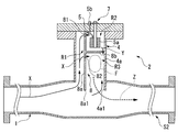
図1は、本実施形態のバーナ装置S1の概略構成を示す断面図である。
このバーナ装置S1は、上流側に配置されるディーゼルエンジン等の排気ガスを排出する装置の排気口と接続され、供給される排気ガスX(酸化剤)と燃料を混合して燃焼させることによって高温ガスZを発生させると共に高温ガスZを後流側のフィルタに供給するための装置である。このバーナ装置S1は、例えばディーゼルエンジンとパティキュレートフィルタとの間に配置される。
そして、このバーナ装置S1は、供給流路1(酸化剤通過流路)と、燃焼部(燃焼領域)2とを備えている。
つまり、本実施形態のバーナ装置S1においては、円形の供給流路1中に、矩形状の壁部4aの端部4a1が配置されている。
この壁部4aの端部4a1は、供給流路1を流れる排気ガスX(酸化剤)の一部を取り込んで、直接保炎領域R3に供給する。
なお、燃料保持部5aは、例えば、金網、焼結金属、金属繊維、ガラス布、セラミック多孔体、セラミックファイバ、軽石等によって形成することができる。
この仕切り部材8では、図1に示すように、中央板8aの底面側に形成された貫通孔81によって排気ガス流路領域R1から着火領域R2に排気ガスXが通気可能となっている。また、側板8bと管体部4の側面との隙間によって着火領域R2から保炎領域R3に混合気Yを通気可能となっている。さらに、中央板8aの中央部には貫通孔82が形成されており、貫通孔82を介して排気ガス流路領域R1に取り込まれた排気ガスの一部が直接保炎領域R3に供給される。
そして、仕切り部材8と管体部4との間に形成された隙間を介して着火領域R2から保炎領域R3に混合気Yを通気することによって、混合気Yの流速が、保炎領域R3において燃焼が安定化される流速に調節される。
また、仕切り部材8の管体部4寄りに開口された上記隙間を介して下方から上方に向けて混合気Yを通気することによって、混合気Yを、保炎領域R3の上方(外部)から管体部4の壁面に沿って保炎領域R3に供給される排気ガスXの流れ(酸化剤流れ)に衝突させる。
なお、着火領域R2における着火性は、排気ガス流路領域R1から着火領域R2への通気面積と、着火領域R2から保炎領域R3への通気面積との比によっても影響されるが、この比は、バーナ装置S1の形状や性能等に応じ適宜設定される。例えば、本実施形態の場合、排気ガス流路領域R1から着火領域R2への通気面積は、着火領域R2から保炎領域R3への通気面積よりも広いことが好ましい。これによって、着火領域R2が常に気体で満たされた状態となり、着火領域R2における流体の流速が低減し、着火性が向上する。一方、排気ガス流路領域R1から着火領域R2への通気面積を、着火領域R2から保炎領域R3への通気面積より狭くした方が、着火領域R2における着火性が向上する場合もある。
そして、中央板8aの端部8a1は、供給流路1を流れる排気ガスXの一部を堰き止めて排気ガス流路領域R1に案内する。
なお、図1に示すように、本実施形態のバーナ装置S1においては、中央板8aの端部8a1の後流側に保炎領域R3が形成されている。その結果、端部8a1によって供給流路1内の排気ガスXの流れが堰き止められることによって排気ガスXの一部が供給流路1側から保炎領域R3に供給される。
一方で、不図示の制御装置による制御下において着火装置7が加熱され、供給部5bから燃料保持部5aに供給された燃料が着火領域R2において揮発する。
そして、着火領域R2に供給された排気ガスXと揮発する燃料とが混合されて混合気Yが生成され、さらに着火装置7によって着火温度以上に加熱されることによって混合気Yが着火される。
なお、排気ガス流路領域R1から着火領域R2への通気面積は、着火領域R2から保炎領域R3への通気面積よりも広く設定されている。これによって、着火領域R2が常に気体で満たされた状態となり、着火領域R2における流体の流速を低減される。したがって、着火領域R2において容易に混合気Yに着火することができる。
したがって、本実施形態のバーナ装置S1によれば、混合気Yの燃焼状態を安定化させ、さらには安定して高温ガスZの生成を行うことが可能となる。
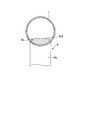
つまり、供給流路1中に晒される中央板8aの端部8a1の面積Sa(図2参照)は、高温ガスZの温度が、触媒が活性化する温度となるように設定されることが好ましい。
一方、供給流路1中に晒される中央板8aの端部8a1の面積Saを0.14Sとした実験では、触媒燃焼器出口の温度が、259℃、290℃、305℃、324℃、246℃、341℃、238℃であった。
また、供給流路1中に晒される中央板8aの端部8a1の面積Saを0.29Sとした実験では、触媒燃焼器出口の温度が、239℃、292℃、311℃、325℃、336℃、352℃、364℃、377℃、390℃、404℃、416℃、432℃、445℃、464℃、477℃、490℃であった。
なお、上記実験においては、バーナ装置S1に排気ガスXを供給するエンジンにおける回転数を1800rpm、トルクを0Nmとした。
また、本発明者らのその後の知見によれば、端部8a1の面積Saが、供給流路1の断面積をSとした場合に、0.45S以下であれば、触媒燃焼器出口の温度が230℃以上となることが判明した。
このため、本発明における端部8a1の面積Saは、供給流路1の断面積をSとした場合に、0.14S~0.45Sであることが好ましく、0.14S~0.29Sであることがさらに好ましい。
なお、供給流路1の断面積に対して端部8a1の面積Saが広すぎる場合には、管体部4内に取り込まれる排気ガスXの量が増加しすぎ、管体部4内における混合気の流速が速くなり、着火不良及び燃焼不良が生じる可能性がある。また、供給流路1の断面積に対して端部8a1の面積Saが広すぎる場合には、供給流路1の流路面積が減少し、バーナ装置S1における圧力損失が大きくなり、排気ガスXを良好に排気することができなくなる可能性もある。
中央板8aの端部8a1の面積Saと供給流路1の断面積との割合を上述のように維持した場合には、管体部4の内部空間を広げた場合であっても、保炎領域R3において火炎Fを維持することができる。このため、本実施形態のバーナ装置S1よりも管体部4の内部空間を広げて着火領域R2を広げることができる。この場合には、着火領域R2における混合気Yの流速が低下し、混合気Yの着火性を向上させることができる。
次に、本発明の第2実施形態について説明する。なお、本実施形態において、上記第1実施形態と同様の部分については、その説明を省略あるいは簡略化する。
つまり、本実施形態のバーナ装置S2においては、管体部4、その内部構造(仕切り部材8、燃料供給部5及び着火装置7)及び接続構造(助燃空気供給装置9)が、供給流路1の上部に取り付けられている。
しかしながら、本発明はこれに限定されるものではなく、管体部4の壁部4aの端部4a1が供給流路1に突出しない構成を採用することも可能である。
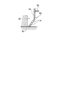
さらに、例えば図5Bに示すように、貫通孔81を、傾斜面8cに形成される複数の孔から形成してもよい。この場合、排気ガスXが複数の貫通孔81に分散して排気ガス流路領域R1から着火領域R2に流入するため、個々の貫通孔81から噴出される排気ガスXの流速が低減される。その結果、着火領域R2内における流体の流速がさらに低減される。
しかしながら、本発明はこれに限定されるものではなく、燃料保持部5aないしは管体部4内に燃料を吹付ける燃料供給部を用いても良い。
さらに、燃料供給部5bに加え、図6に示すように、保炎領域R3に燃料を供給する第2の燃料供給部5b´を、管体部4の壁部4aに、保炎領域R3に向け設けてもよい。
第2の燃料供給部5b´を設けることにより、着火領域R2に供給する燃料と保炎領域R3に供給する燃料との分配を細かく調整することが可能となり、より安定した燃焼が期待できる。
Claims (3)
- 酸化剤と燃料との混合気の燃焼を行うバーナ装置であって、
前記酸化剤が通過する酸化剤通過流路と、内部が中空とされると共にこの内部が前記酸化剤通過流路に対して接続される管体部と、管体部の内部を前記酸化剤の取込流路領域と前記混合気に着火する着火領域と前記混合気の燃焼を維持する保炎領域とに通気可能に区分けする仕切り部材とを備え、
仕切り部材が、前記酸化剤通過流路に飛び出し、前記酸化剤通過流路を流れる前記酸化剤の一部を堰き止めて前記取込流路領域に案内する突出部を備える
バーナ装置。 - 前記突出部の後流側に前記保炎領域が配置されている請求項1に記載のバーナ装置。
- 前記酸化剤通過流路中に晒される前記突出部の面積が、前記酸化剤通過流路の断面積をSとした場合に、0.14~0.29Sである請求項1または2に記載のバーナ装置。
Priority Applications (6)
| Application Number | Priority Date | Filing Date | Title |
|---|---|---|---|
| JP2012507034A JP5494795B2 (ja) | 2010-03-24 | 2011-03-23 | バーナ装置 |
| CA2794191A CA2794191C (en) | 2010-03-24 | 2011-03-23 | Burner device |
| CN201180015169.9A CN102803850B (zh) | 2010-03-24 | 2011-03-23 | 燃烧器装置 |
| US13/635,937 US8827694B2 (en) | 2010-03-24 | 2011-03-23 | Burner device |
| EP11759440.8A EP2551588B1 (en) | 2010-03-24 | 2011-03-23 | Burner device |
| KR1020127027325A KR101343931B1 (ko) | 2010-03-24 | 2011-03-23 | 버너 장치 |
Applications Claiming Priority (2)
| Application Number | Priority Date | Filing Date | Title |
|---|---|---|---|
| JP2010-068092 | 2010-03-24 | ||
| JP2010068092 | 2010-03-24 |
Publications (1)
| Publication Number | Publication Date |
|---|---|
| WO2011118635A1 true WO2011118635A1 (ja) | 2011-09-29 |
Family
ID=44673185
Family Applications (1)
| Application Number | Title | Priority Date | Filing Date |
|---|---|---|---|
| PCT/JP2011/056985 Ceased WO2011118635A1 (ja) | 2010-03-24 | 2011-03-23 | バーナ装置 |
Country Status (7)
| Country | Link |
|---|---|
| US (1) | US8827694B2 (ja) |
| EP (1) | EP2551588B1 (ja) |
| JP (1) | JP5494795B2 (ja) |
| KR (1) | KR101343931B1 (ja) |
| CN (1) | CN102803850B (ja) |
| CA (1) | CA2794191C (ja) |
| WO (1) | WO2011118635A1 (ja) |
Cited By (5)
| Publication number | Priority date | Publication date | Assignee | Title |
|---|---|---|---|---|
| JP2014047685A (ja) * | 2012-08-30 | 2014-03-17 | Ihi Corp | 排気システム |
| JP2014047699A (ja) * | 2012-08-31 | 2014-03-17 | Ihi Corp | 燃料噴射方法および排気システム |
| JP2014047687A (ja) * | 2012-08-30 | 2014-03-17 | Ihi Corp | 排気システム |
| JP2014047689A (ja) * | 2012-08-30 | 2014-03-17 | Ihi Corp | 排気システム |
| CN103899388A (zh) * | 2012-12-26 | 2014-07-02 | 株式会社久保田 | 发动机的废气处理装置 |
Families Citing this family (3)
| Publication number | Priority date | Publication date | Assignee | Title |
|---|---|---|---|---|
| JP5353822B2 (ja) | 2009-09-30 | 2013-11-27 | 株式会社Ihi | 着火装置 |
| KR101319256B1 (ko) * | 2012-03-05 | 2013-10-17 | 주식회사 경동나비엔 | 연소기기용 가스 공기 혼합장치 |
| MX2012006599A (es) * | 2012-06-08 | 2013-12-16 | Jorge Rivera Garza | Quemador de combustible gaseoso con elevada eficiencia energetica y de combustion, baja emision de contaminantes y mayor transferencia de calor. |
Citations (5)
| Publication number | Priority date | Publication date | Assignee | Title |
|---|---|---|---|---|
| JPH0893555A (ja) * | 1994-07-26 | 1996-04-09 | Ishikawajima Harima Heavy Ind Co Ltd | ラム燃焼装置 |
| JP2000110548A (ja) * | 1998-10-01 | 2000-04-18 | Mitsubishi Heavy Ind Ltd | 黒煙除去装置 |
| JP2005265344A (ja) * | 2004-03-19 | 2005-09-29 | Samson Co Ltd | パイロットバーナ部を持った予混合式ガスバーナ |
| JP2007154772A (ja) | 2005-12-06 | 2007-06-21 | Mitsubishi Fuso Truck & Bus Corp | 内燃機関の制御装置 |
| JP2010068092A (ja) | 2008-09-09 | 2010-03-25 | Sony Corp | デジタルアナログ変換器および映像表示装置 |
Family Cites Families (43)
| Publication number | Priority date | Publication date | Assignee | Title |
|---|---|---|---|---|
| US1650342A (en) * | 1918-05-01 | 1927-11-22 | Good Inventions Co | Inclosed liquid-fuel burner |
| US3366373A (en) * | 1965-06-21 | 1968-01-30 | Zink Co John | Apparatus for adding heat to gas turbine exhaust |
| US3423928A (en) * | 1967-05-26 | 1969-01-28 | Gulf Research Development Co | Afterburner |
| US3593969A (en) * | 1969-10-09 | 1971-07-20 | Oxy Catalyst Inc | Gas stream heater |
| JPS5113618Y2 (ja) * | 1972-03-15 | 1976-04-12 | ||
| US3829281A (en) * | 1972-06-12 | 1974-08-13 | Koehring Co | Burner module for application to an air intake manifold or other gas flow conduit |
| FR2491128A1 (fr) * | 1979-11-02 | 1982-04-02 | Leistritz Hans | Procede et dispositif pour le recyclage thermiquement optimal dans des appareils d'echappement a postcombustion de moteurs thermiques |
| JPS56161712A (en) * | 1980-05-17 | 1981-12-12 | Sony Corp | Filter circuit |
| US4383411A (en) | 1981-08-10 | 1983-05-17 | General Motors Corporation | Diesel exhaust cleaner with burner vortex chamber |
| US4505106A (en) * | 1981-12-02 | 1985-03-19 | Robertshaw Controls Company | Exhaust system for an internal combustion engine, burn-off unit and methods therefor |
| JPS59144106U (ja) * | 1983-03-18 | 1984-09-26 | 日産自動車株式会社 | 排気微粒子捕集用トラツプの再生用バ−ナ− |
| FR2548264B1 (fr) * | 1983-06-16 | 1985-12-13 | Renault | Regeneration des filtres a particules, notamment pour moteurs diesel |
| JPS60135612A (ja) * | 1983-12-22 | 1985-07-19 | Nissan Motor Co Ltd | 内燃機関の排気微粒子処理装置 |
| JPS61128323A (ja) | 1984-11-28 | 1986-06-16 | Hitachi Ltd | グラフイツクデイスプレイ装置 |
| JPS61128323U (ja) * | 1985-01-30 | 1986-08-12 | ||
| DE3632696A1 (de) * | 1986-09-26 | 1988-04-07 | Opel Adam Ag | Kraftfahrzeug mit einem dieselmotor |
| DE8718031U1 (de) * | 1987-03-27 | 1993-01-14 | Zeuna-Stärker GmbH & Co KG, 8900 Augsburg | Hochleistungsbrenner |
| JPS6414726A (en) | 1987-07-09 | 1989-01-18 | Matsushita Electric Industrial Co Ltd | Production of magnetic recording medium |
| FR2635143B1 (fr) * | 1988-08-05 | 1993-11-05 | Peugeot Automobiles | Dispositif de traitement des gaz d'echappement d'un moteur a combustion interne a deux temps |
| DE3828248A1 (de) * | 1988-08-19 | 1990-02-22 | Webasto Ag Fahrzeugtechnik | Verfahren zum betreiben eines brenners und brenner hierfuer |
| DE3837472C2 (de) * | 1988-11-04 | 1998-09-24 | Deutz Ag | Partikelfiltersystem |
| DE3841182A1 (de) * | 1988-12-07 | 1990-06-13 | Bosch Gmbh Robert | Einrichtung zum entfernen von festkoerperpartikeln, insbesondere russteilchen, aus dem abgas von brennkraftmaschinen |
| JPH08580Y2 (ja) | 1989-11-16 | 1996-01-10 | 株式会社ゼクセル | 燃焼式暖房装置 |
| US5339630A (en) * | 1992-08-28 | 1994-08-23 | General Motors Corporation | Exhaust burner catalyst preheater |
| KR950014592A (ko) | 1993-11-10 | 1995-06-16 | 스크롤 압축기의 실링구조 | |
| JPH08135911A (ja) | 1994-11-01 | 1996-05-31 | Miura Kenkyusho:Kk | 触媒燃焼装置 |
| DE4440716C2 (de) * | 1994-11-15 | 1997-02-27 | Daimler Benz Ag | Rußfilteranlage für Verbrennungsmotor |
| DE19504183A1 (de) * | 1995-02-09 | 1996-08-14 | Eberspaecher J | Brenner zur thermischen Regeneration eines Partikelfilters in einem Abgasnachbehandlungssystem eines Verbrennungsmotors, insbesondere Dieselmotors |
| JP3341800B2 (ja) | 1995-03-23 | 2002-11-05 | イビデン株式会社 | Dpfバーナー再生装置 |
| US5771683A (en) * | 1995-08-30 | 1998-06-30 | Southwest Research Institute | Active porous medium aftertreatment control system |
| US5829248A (en) | 1997-06-19 | 1998-11-03 | Environmental Engineering Corp. | Anti-pollution system |
| JP2941800B1 (ja) | 1998-09-09 | 1999-08-30 | 三菱重工業株式会社 | 黒煙除去装置 |
| JP4404558B2 (ja) | 2003-02-12 | 2010-01-27 | 日本碍子株式会社 | 排気ガス処理装置 |
| DE102004048336A1 (de) * | 2004-10-01 | 2006-04-13 | J. Eberspächer GmbH & Co. KG | Abgasanlage für eine Brennkraftmaschine |
| JP2006161768A (ja) * | 2004-12-10 | 2006-06-22 | Hino Motors Ltd | 排気浄化装置 |
| JP4553363B2 (ja) | 2005-02-17 | 2010-09-29 | ボッシュ株式会社 | パティキュレート量の測定装置、パティキュレート量の測定方法、及び排気浄化装置 |
| JP4614448B2 (ja) | 2005-11-25 | 2011-01-19 | ボッシュ株式会社 | 内燃機関の排気浄化装置 |
| JP2007147161A (ja) * | 2005-11-28 | 2007-06-14 | Electric Power Dev Co Ltd | 燃焼装置の排ガス処分方法及び装置 |
| JP4659097B2 (ja) * | 2006-08-01 | 2011-03-30 | コリア・インスティテュート・オブ・マシナリー・アンド・マテリアルズ | プラズマ反応装置およびこれを用いた排気ガス内の粒子状物質の低減システム |
| JP4332756B2 (ja) * | 2007-12-25 | 2009-09-16 | 三菱自動車工業株式会社 | 内燃機関の排気ガス浄化装置 |
| JP5141900B2 (ja) * | 2008-07-30 | 2013-02-13 | 三菱自動車工業株式会社 | 排気浄化装置 |
| JP5335315B2 (ja) * | 2008-08-11 | 2013-11-06 | 日野自動車株式会社 | 排気浄化装置 |
| JP4720935B2 (ja) | 2009-07-14 | 2011-07-13 | 株式会社Ihi | バーナ装置 |
-
2011
- 2011-03-23 CN CN201180015169.9A patent/CN102803850B/zh active Active
- 2011-03-23 CA CA2794191A patent/CA2794191C/en not_active Expired - Fee Related
- 2011-03-23 JP JP2012507034A patent/JP5494795B2/ja active Active
- 2011-03-23 KR KR1020127027325A patent/KR101343931B1/ko not_active Expired - Fee Related
- 2011-03-23 WO PCT/JP2011/056985 patent/WO2011118635A1/ja not_active Ceased
- 2011-03-23 EP EP11759440.8A patent/EP2551588B1/en active Active
- 2011-03-23 US US13/635,937 patent/US8827694B2/en active Active
Patent Citations (5)
| Publication number | Priority date | Publication date | Assignee | Title |
|---|---|---|---|---|
| JPH0893555A (ja) * | 1994-07-26 | 1996-04-09 | Ishikawajima Harima Heavy Ind Co Ltd | ラム燃焼装置 |
| JP2000110548A (ja) * | 1998-10-01 | 2000-04-18 | Mitsubishi Heavy Ind Ltd | 黒煙除去装置 |
| JP2005265344A (ja) * | 2004-03-19 | 2005-09-29 | Samson Co Ltd | パイロットバーナ部を持った予混合式ガスバーナ |
| JP2007154772A (ja) | 2005-12-06 | 2007-06-21 | Mitsubishi Fuso Truck & Bus Corp | 内燃機関の制御装置 |
| JP2010068092A (ja) | 2008-09-09 | 2010-03-25 | Sony Corp | デジタルアナログ変換器および映像表示装置 |
Non-Patent Citations (1)
| Title |
|---|
| See also references of EP2551588A4 |
Cited By (7)
| Publication number | Priority date | Publication date | Assignee | Title |
|---|---|---|---|---|
| JP2014047685A (ja) * | 2012-08-30 | 2014-03-17 | Ihi Corp | 排気システム |
| JP2014047687A (ja) * | 2012-08-30 | 2014-03-17 | Ihi Corp | 排気システム |
| JP2014047689A (ja) * | 2012-08-30 | 2014-03-17 | Ihi Corp | 排気システム |
| JP2014047699A (ja) * | 2012-08-31 | 2014-03-17 | Ihi Corp | 燃料噴射方法および排気システム |
| CN103899388A (zh) * | 2012-12-26 | 2014-07-02 | 株式会社久保田 | 发动机的废气处理装置 |
| EP2749743A1 (en) * | 2012-12-26 | 2014-07-02 | Kubota Corporation | Exhaust treatment apparatus for an engine |
| US9200551B2 (en) | 2012-12-26 | 2015-12-01 | Kubota Corporation | Exhaust treatment apparatus for engine |
Also Published As
| Publication number | Publication date |
|---|---|
| KR20130016307A (ko) | 2013-02-14 |
| JP5494795B2 (ja) | 2014-05-21 |
| CA2794191A1 (en) | 2011-09-29 |
| EP2551588A4 (en) | 2017-12-13 |
| CA2794191C (en) | 2014-12-09 |
| US20130011801A1 (en) | 2013-01-10 |
| EP2551588B1 (en) | 2019-01-30 |
| JPWO2011118635A1 (ja) | 2013-07-04 |
| EP2551588A1 (en) | 2013-01-30 |
| CN102803850A (zh) | 2012-11-28 |
| KR101343931B1 (ko) | 2013-12-20 |
| US8827694B2 (en) | 2014-09-09 |
| CN102803850B (zh) | 2015-03-25 |
Similar Documents
| Publication | Publication Date | Title |
|---|---|---|
| JP5494795B2 (ja) | バーナ装置 | |
| JP5353822B2 (ja) | 着火装置 | |
| JP5446741B2 (ja) | バーナ装置 | |
| JP4720935B2 (ja) | バーナ装置 | |
| CN102472491B (zh) | 燃烧器装置 | |
| JP5671794B2 (ja) | バーナ装置 | |
| JP5568996B2 (ja) | バーナ装置 | |
| JP5521465B2 (ja) | バーナ装置 | |
| JP5402474B2 (ja) | バーナ装置 | |
| JP5428712B2 (ja) | バーナ装置 | |
| JP5549915B2 (ja) | バーナ装置 | |
| JP5742128B2 (ja) | バーナ装置 | |
| JP5482113B2 (ja) | バーナ装置 | |
| JP5569628B2 (ja) | 着火装置 | |
| JP5516009B2 (ja) | 着火装置 |
Legal Events
| Date | Code | Title | Description |
|---|---|---|---|
| WWE | Wipo information: entry into national phase |
Ref document number: 201180015169.9 Country of ref document: CN |
|
| 121 | Ep: the epo has been informed by wipo that ep was designated in this application |
Ref document number: 11759440 Country of ref document: EP Kind code of ref document: A1 |
|
| WWE | Wipo information: entry into national phase |
Ref document number: 2012507034 Country of ref document: JP |
|
| WWE | Wipo information: entry into national phase |
Ref document number: 13635937 Country of ref document: US |
|
| ENP | Entry into the national phase |
Ref document number: 2794191 Country of ref document: CA |
|
| NENP | Non-entry into the national phase |
Ref country code: DE |
|
| WWE | Wipo information: entry into national phase |
Ref document number: 2011759440 Country of ref document: EP |
|
| ENP | Entry into the national phase |
Ref document number: 20127027325 Country of ref document: KR Kind code of ref document: A |