WO2011121991A1 - 直流モータ - Google Patents
直流モータ Download PDFInfo
- Publication number
- WO2011121991A1 WO2011121991A1 PCT/JP2011/001850 JP2011001850W WO2011121991A1 WO 2011121991 A1 WO2011121991 A1 WO 2011121991A1 JP 2011001850 W JP2011001850 W JP 2011001850W WO 2011121991 A1 WO2011121991 A1 WO 2011121991A1
- Authority
- WO
- WIPO (PCT)
- Prior art keywords
- segment
- segments
- concentrated winding
- unit
- motor
- Prior art date
- Legal status (The legal status is an assumption and is not a legal conclusion. Google has not performed a legal analysis and makes no representation as to the accuracy of the status listed.)
- Ceased
Links
Images





Classifications
-
- H—ELECTRICITY
- H02—GENERATION; CONVERSION OR DISTRIBUTION OF ELECTRIC POWER
- H02K—DYNAMO-ELECTRIC MACHINES
- H02K23/00—DC commutator motors or generators having mechanical commutator; Universal AC/DC commutator motors
- H02K23/26—DC commutator motors or generators having mechanical commutator; Universal AC/DC commutator motors characterised by the armature windings
- H02K23/30—DC commutator motors or generators having mechanical commutator; Universal AC/DC commutator motors characterised by the armature windings having lap or loop windings
-
- H—ELECTRICITY
- H02—GENERATION; CONVERSION OR DISTRIBUTION OF ELECTRIC POWER
- H02K—DYNAMO-ELECTRIC MACHINES
- H02K23/00—DC commutator motors or generators having mechanical commutator; Universal AC/DC commutator motors
- H02K23/26—DC commutator motors or generators having mechanical commutator; Universal AC/DC commutator motors characterised by the armature windings
- H02K23/38—DC commutator motors or generators having mechanical commutator; Universal AC/DC commutator motors characterised by the armature windings having winding or connection for improving commutation, e.g. equipotential connection
Definitions
- the present invention relates to a DC motor having a brush and a commutator, for example, a DC motor used for electrical equipment and electric tools mounted on an automobile.
- the general configuration of this DC motor includes a stator that forms a field, and a rotor that is disposed so as to face the stator via an annular gap.
- a so-called armature having a commutator and a coil wound around a core is used as the rotor.
- armature having a commutator and a coil wound around a core is used as the rotor.
- a brush connected to an external power source is brought into sliding contact with the commutator by a lead wire or the like.
- FIG. 8 is a development view showing a winding method of an armature coil of a conventional DC motor.
- This conventional DC motor includes a stator having 4 field poles, a core having 5 teeth, a commutator having 10 segments, and an armature having coils wound around the teeth via connection to the segments, Both brush pieces are arranged orthogonal to each other, and include a pair of brushes that are in sliding contact with the commutator.
- the rotational arc length in sliding contact with the commutator in the brush is configured to be equal to or less than 1/20 ( ⁇ ⁇ A / 20, where A is the commutator outer diameter) of the outer peripheral length of the commutator.
- FIG. 8 shows a state in which the brush piece B101 has a positive voltage and is in sliding contact with the segment S103, and the brush piece B102 has a negative voltage and is in sliding contact with the segment S105.
- the energization state of each coil is as follows. It is. In FIG. 8, the left and right circle numbers 1, 2, 3, and 4 indicate that the same number is connected.
- the first current route flows from the brush piece B101 to the tooth T105 via S103, relays S108 to flow around the tooth T104, relays S109 to flow around the tooth T103, and relays S104. Then, it flows around the tooth T102 and reaches the brush piece B102 via S105.
- the second current route flows from the brush piece B101 through the tooth T101 through S103, relays through S102 and flows around the tooth T102, relays through S107 and flows around the tooth T103, and relays S106.
- improvements have been made to required specifications, efforts have been made to optimize the configuration of DC motors, and various techniques have been disclosed. (For example, patent document 1 and patent document 2).
- the DC motor of the present invention is a DC motor provided with a stator, an armature, and a brush.
- the stator has a plurality of field poles.
- the armature includes a plurality of teeth and an armature core having a slot between the teeth, an armature coil wound around the tooth and housed in the slot, and a commutator having a group of segments.
- the brush slidably contacts the segment and supplies power to the armature coil.
- the armature coil includes a plurality of concentrated winding coil units wound around each tooth by concentrated winding, and a plurality of jumper units that connect and electrically connect the concentrated winding coil units to each other. Including.
- the segment group includes a first segment to which one end of the concentrated winding coil unit is connected, a second segment to which the other end of the concentrated winding coil unit is connected, and a third segment to which only the jumper unit is connected. Including segments. Further, the first segment and the second segment are arranged adjacent to each other, and the third segment is arranged next to the adjacent arrangement.
- the DC motor according to the present invention includes a crossover unit in which a plurality of crossover units connect between the concentrated winding coil units through the slot.
- the direct current motor of the present invention can suppress the generation of sparks between commutator segments, and can improve driving efficiency and reduce size and weight.
- FIG. 1 is a half sectional view in the axial direction of a DC motor according to an embodiment of the present invention.
- FIG. 2 is a side view of the DC motor with the bracket removed.
- FIG. 3 is an exploded view of the winding of the DC motor.
- FIG. 4 is a winding development view showing the position of the slot for accommodating the crossover unit C1 of the DC motor.
- FIG. 5 is a diagram showing the connection of the crossover unit C1 of the DC motor.
- FIG. 6 is a winding development view showing the position of the slot for accommodating the crossover unit C2 of the DC motor.
- FIG. 7 is a winding development view showing the position of the slot for accommodating the crossover unit C1 when the distance between the brushes of the DC motor is 60 degrees.
- FIG. 8 is an exploded view of a winding of a conventional DC motor.
- FIG. 1 is a half sectional view in the axial direction of a DC motor according to the present embodiment.
- the stator 11 includes a magnet 12 on the inner peripheral surface of a bottomed hollow cylindrical frame 13 and is configured to cover an open end with a bracket 17. Further, the bracket 17 is provided with a brush 31 via a brush holder 32.
- a rotor (hereinafter referred to as an armature) 21 includes a substantially arc-shaped armature core 23 having a plurality of slots 24, an armature coil 22 wound and accommodated in the slots 24, and an armature core 23.
- the output shaft 28 is fixed to the center of the shaft in the axial direction, and the commutator 25 is fixed to the output shaft 28.
- the terminal of the armature coil 22 is electrically connected to the segment of the commutator 25.
- the output shaft 28 is rotatably supported by a bearing 35 having an outer ring fixed to the frame 13 and a bearing 36 having an outer ring fixed to the bracket 17.
- the outer periphery of the armature core 23 of the armature 21 and the inner periphery of the magnet 12 of the stator 11 are opposed to each other with a predetermined gap.
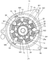
- FIG. 2 is a side view of the DC motor according to the embodiment of the present invention with the bracket 17 removed. The structure of the DC motor according to the present invention will be described in more detail with reference to FIG.
- the frame 13 constituting the stator 11 has mounting holes 18 at three locations and a magnet 12 on the inner peripheral surface.
- the magnet 12 is divided into three parts, and a magnet fixing spring 15 is provided between them, and is fixed to the inner peripheral surface of the frame 13 by adhesion.
- Each magnet 12 is magnetized to a pair of field poles of N and S poles. Therefore, the entire circumference is magnetized with the number of field poles.
- the magnet 12 may have a ring shape, and the inner wall thereof may be magnetized in six poles alternately at an equal interval with the N pole-S pole in the circumferential direction.
- the magnet 12 may be six arc-shaped magnets individually magnetized with an N pole and an S pole.
- the armature 21 includes a plurality of teeth (eight in this embodiment), an armature core 23 having a slot 24 therebetween, and an armature coil wound around each tooth and housed in the slot 24. 22, an output shaft 28 penetrating and fixing the center of the armature core 23 in the axial direction, and a commutator 25 fixed to the output shaft 28.
- the armature core 23 is configured by laminating electromagnetic steel plates. Each tooth T1, T2, T3, T4, T5, T6, T7, T8 of the armature core 23 has concentrated winding coil units W1, W2, W3, W4, W5, W6, W7, W8 in concentrated winding. It is wound and connected to a segment 25s of the commutator 25 via a hook 25f. Details of this winding structure will be described later.
- FIG. 2 shows the stator 11 and the armature 21 as viewed from above.
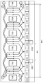
- FIG. 3 is a winding development view showing basic wiring of the winding of the DC motor in the present embodiment. Details of specific wiring of the winding will be further described below.
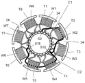
- the armature core 23 includes eight teeth T1, T2, T3, T4, T5, T6, T7, and T8, and the same number of slots 24 between the teeth.
- the armature coil 22 includes eight concentrated winding coil units (hereinafter simply referred to as coil units as appropriate) W1, W2, W3, W4, W5, W6, W7, W8 and a plurality of crossover units C1, C2, C3. , C4, C5, C6, C7, and C8.
- Each of the coil units W1, W2, W3, W4, W5, W6, W7, W8 is wound around each of the teeth T1, T2, T3, T4, T5, T6, T7, T8 in a concentrated winding. 24. That is, for example, a winding is wound around the tooth T1 a plurality of times, thereby forming a coil unit W1.
- the commutator 25 includes 24 segments, segment S1 to segment S24, as each segment 25s.
- the segments 25s are insulated from each other, and a hook 25f for connecting a coil terminal is provided at the tip of the segment 25s.
- the terminal of the coil unit or the crossover unit is connected to each segment, it is connected to the hook 25f at the tip of the segment 25s, but is hereinafter appropriately abbreviated as “connected to the segment”.
- the brush 31 is composed of a pair of anode-side brush pieces B1 and cathode-side brush pieces B2 disposed at a mechanical angle of 180 degrees, and is in sliding contact with each segment 25s of the commutator 25.
- the anode-side brush piece B1 and the cathode-side brush piece B2 are connected to a DC power source and configured to be fed to the armature coil 22 via the commutator 25.
- the angle indicates a mechanical angle.
- the coil units W1, W2, W3, W4, W5, W6, W7, and W8 constituting the armature coil 22 are connected to adjacent segments 25s. That is, one terminal of the coil unit is connected to one segment 25s, and the other terminal is connected to the adjacent segment 25s. Then, adjacent winding segments are connected to adjacent segments to which these coil units are connected, and only the jumper unit is connected (details will be described later).
- a segment to which one end of these concentrated winding coil units is connected is defined as a first segment
- a segment to which the other end of the concentrated winding coil unit is connected is defined as a second segment.
- a segment to which only the crossover unit is connected is defined as a third segment.
- the first segment and the second segment are arranged adjacent to each other, and the third segment is arranged next to the adjacent arrangement. Furthermore, this armature coil constitutes a series closed circuit through these segment groups and a crossover unit.
- the first segment number, the second segment number, and the third segment number are the same, and the total number of segments of the segment group is the first segment number, the second segment number, and the third segment. The sum of numbers.
- the number of segments in the segment group is 24, and therefore the segment pitch is 15 degrees.
- the first segments, the second segments, and the third segments are all arranged at 45 ° intervals.
- the second segment or the third segment is arranged at a position at an interval of 120 degrees.
- any second segment has a third segment or first segment located at 120 degree intervals
- any third segment has a first segment or first segment at 120 degree intervals.
- Two segments are arranged. The first segment, the second segment, and the third segment are connected to each other by a crossover unit.
- the concentrated winding coil unit W1 wound around the tooth T1 is connected to the first segment S2 and the second segment S3.
- the concentrated winding coil unit W2 wound around the tooth T2 is connected to the first segment S5 and the second segment S6.
- the concentrated winding coil unit W3 wound around the tooth T3 is connected to the first segment S8 and the second segment S9.
- the concentrated winding coil unit W4 wound around the tooth T4 is connected to the first segment S11 and the second segment S12.
- the concentrated winding coil unit W5 wound around the tooth T5 is connected to the first segment S14 and the second segment S15.
- the concentrated winding coil unit W6 wound around the tooth T6 is connected to the first segment S17 and the second segment S18.
- the concentrated winding coil unit W7 wound around the tooth T7 is connected to the first segment S20 and the second segment S21.
- the concentrated winding coil unit W8 wound around the tooth T8 is connected to the first segment S23 and the second segment S24.
- crossover units C1, C2, C3, C4, C5, C6, C7, and C8 connected to the third segments S1, S4, S7, S10, S13, S16, S19, and S22 will be described.
- These crossover units connect the concentrated winding coil units to each other for electrical connection.
- These crossover units connect the first segment, the second segment, and the third segment located at intervals of 120 degrees, specifically as follows.
- the crossover unit C1 is connected to the first segment S2, the third segment S10, and the second segment S18.
- the crossover unit C2 is connected to the first segment S5, the third segment S13, and the second segment S21.
- the crossover unit C3 is connected to the first segment S8, the third segment S16, and the second segment S24.
- the crossover unit C4 is connected to the first segment S11, the third segment S19, and the second segment S3.
- the crossover unit C5 is connected to the first segment S14, the third segment S22, and the second segment S6.
- the crossover unit C6 is connected to the first segment S17, the third segment S1, and the second segment S9.
- the crossover unit C7 is connected to the first segment S20, the third segment S4, and the second segment S12.
- the crossover unit C8 is connected to the first segment S23, the third segment S7, and the second segment S15.
- the armature coil 22 forms a closed circuit by connecting each concentrated winding coil unit and the crossover unit to each segment.
- the result is as follows. S1-S9-W3-S8-S16-S24-W8-S23-S7-S15-W5-S14-S22-S6-W2-S5-S13-S21-W7-S20-S4-S12-W4-S11-S19- S3-W1-S2-S10-S18-W6-S17-S1 and one connection loop is formed, indicating that a closed circuit is formed.
- the crossover units C1, C2, C3, C4, C5, C6, C7, and C8 described above can rationalize the connection man-hours by performing the connection method described below.
- One end of the concentrated winding coil unit W1 wound around the tooth T1 is connected to the first segment S2, and then extended without being cut there and connected to the third segment S10.
- the other end of the concentrated winding coil unit W6 wound around the tooth T6 is connected to the second segment S18 and then extended without being cut there, and is connected to the third segment S10.
- the crossover unit C1 can be constituted by an extension line at one end of the concentrated winding coil unit W1 and an extension line at the other end of the concentrated winding coil unit W6, and the connection man-hour can be rationalized.
- the crossover units C2, C3, C4, C5, C6, C7, and C8 can also be configured in the same manner as the crossover unit C1.
- such a plurality of crossover units include a crossover unit that connects the concentrated winding coil units through the slot 24. That is, each of these crossover units C1, C2, C3, C4, C5, C6, C7, and C8 is not connected on the outer periphery of the commutator, but together with each concentrated winding coil unit, the armature slot 24 Wrapped in and connected. Accordingly, it is possible to reduce the size of the motor by effectively utilizing the space in the slot 24 of the armature without generating extra space for connecting the wiring unit around the commutator.
- the anode-side brush piece B1 and the cathode-side brush piece B2 are equiangular (180 degrees) with each other so that the center line in the width direction (circumferential direction) coincides with the center line in the circumferential direction of the predetermined magnet 12. It arrange
- the current flowing from the segment S2 flows from the segment S18 to the concentrated winding coil unit W6, passes through the segment S17 and the segment S9, flows to the concentrated winding coil unit W3, and passes through the segment S8 and the segment S24 to the concentrated winding coil unit W8. And flows out from the segment S15 via the segment S23.
- the current flowing from segment S3 flows through concentrated winding coil unit W4 from segment S11, flows through concentrated winding coil unit W7 via segment S12 and segment S20, and concentrated winding via segment S21 and segment S5. It flows through the coil unit W2 and flows out from the segment S14 via the segment S6.
- the direction in which these currents flow is indicated by arrows in each concentrated winding coil unit in FIG.
- the current flowing from the segment S2 flows through the series circuit of the concentrated winding coil units W6, W3, and W8 and flows out from the segment S15, and the current flowing from the segment S3 is the concentrated winding coil units W4, W7, and W2. Flows out from the segment S14.
- the current flowing in from the anode brush piece B1 flows in two parallel circuits and flows out from the cathode brush piece B2. With such a current flow, the DC motor having this configuration can be started automatically.
- FIG. 4 shows a specific wiring example of the crossover unit in the present embodiment.
- the plurality of crossover units include a crossover unit that connects the concentrated winding coil units through the slot 24. That is, the crossover units C1, C2, C3, C4, C5, C6, C7, and C8 are not connected on the outer periphery of the commutator, but are housed in the armature slot 24 together with the respective concentrated winding coil units. Connected to each segment. In that case, the slot 24 is selected that has the same timing as the current direction of the concentrated winding coil unit.
- FIG. 4 specifically shows the position of the slot 24 that houses the crossover unit C1.
- the crossover unit C1 passes from the first segment S2 through the slot 24 between the teeth T1 and T2, passes through the slot 24 between the teeth T2 and T3, and is connected to the third segment S10. Further, the third segment S10 passes through the slot 24 between the teeth T3 and T4, passes through the slot 24 between the teeth T5 and T6, and is connected to the second segment S18.
- FIG. 5 is a diagram more specifically showing the connection of the crossover unit C1 shown in FIG.
- the crossover unit C ⁇ b> 1 coming out of the first segment S ⁇ b> 2 disposed on the upper surface of the armature core 23 passes through the slot 24 between the teeth T ⁇ b> 1 and the teeth T ⁇ b> 2 and is on the lower surface side of the armature core 23.
- it passes through the lower surface side of the tooth T2
- passes through the slot 24 between the tooth T2 and the tooth T3 returns to the upper surface side, and is connected to the third segment S10.
- the crossover unit C1 exiting from the third segment S10 passes through the slot 24 between the teeth T3 and T4, reaches the lower surface side of the armature core 23, passes through the lower surface side of the teeth T4 and the teeth T5, It passes through the slot 24 between the teeth T5 and T6, returns to the upper surface side, and is connected to the second segment S18.
- the crossover unit coming out of the segment passes through a certain slot 24 to reach the opposite surface side of the armature core, and passes through the lower surface side of the teeth to the other slot.
- the connection includes passing through 24 and returning to the third segment.
- the current direction of the crossover unit C1 and the concentrated winding coil unit is the same in each slot 24 as indicated by the arrow in the current direction in each slot 24 of the crossover unit C1. Since the brush position changes due to the rotation of the motor, the current direction changes accordingly, and the current direction of the crossover unit and the concentrated winding coil unit does not always match. Is selected and stored.
- FIGS. 4 and 5 an example is given in which the crossover unit C1 is wound half a turn around the teeth T2 and half a turn around the teeth T4 and T5.
- the number of windings is appropriately determined.
- FIG. 6 shows the position of the slot 24 for accommodating the crossover unit C2.
- the crossover unit C2 passes through the slot 24 between the teeth T2 and T3 from the first segment S5, passes through the slot 24 between the teeth T3 and T4, and is connected to the third segment S13.
- the third segment S13 passes through the slot 24 between the teeth T4 and T5, passes through the slot 24 between the teeth T6 and T7, and is connected to the second segment S21.
- the current direction in each slot 24 of the crossover unit C2 is indicated by an arrow, in each slot 24, the current direction of the crossover unit C2 and the concentrated winding coil unit is the same.
- the crossover unit C2 may be wound around the teeth for a plurality of turns, and the number of windings is appropriately determined.
- slot 24 for accommodating the jumper units C1 and C2 is shown.
- the other jumper units C3, C4, C5, C6, C7, and C8 are similarly arranged in the current direction of the concentrated winding coil unit. Slot 24 can be selected to match.
- all of the plurality of crossover units C1, C2, C3, C4, C5, C6, C7, and C8 are connected to each other between the concentrated winding coil units through the slot 24 as described above. It is preferable to do.
- some crossover units may be configured to connect the concentrated winding coil units only on the upper surface side of the armature core 23. That is, it is only necessary to include a crossover unit in which a plurality of crossover units pass through the slot 24 and connect the concentrated winding coil units to each other. As a result, the bulging of the crossover units that occur when the crossover units are densely arranged around the commutator can be suppressed, and the size of the DC motor can be reduced.
- the anode side brush piece B1 and the cathode side brush piece B2 are arranged at an interval of 180 degrees, but instead of the configuration of FIG. 4, as shown in FIG. Good. That is, the cathode side brush piece B3 is arranged at an interval of 60 degrees with respect to the anode side brush piece B1.
- the anode side brush piece B1 is in sliding contact with the segments S2 and S3
- the cathode side brush piece B3 having an interval of 60 degrees is in contact with the segments S6 and S7.
- the current flow is It becomes as follows.
- the current flowing from the segment S2 flows from the segment S18 to the concentrated winding coil unit W6, passes through the segment S17 and the segment S9, flows to the concentrated winding coil unit W3, and passes through the segment S8 and the segment S24 to the concentrated winding coil unit W8. And flows out from segment S7 via segment S23.
- the current flowing from segment S3 flows through concentrated winding coil unit W4 from segment S11, flows through concentrated winding coil unit W7 via segments S12 and S20, and concentrated winding via segments S21 and S5. It flows through the coil unit W2 and flows out from the segment S6.
- the direction in which these currents flow is indicated by arrows on each concentrated winding coil unit in FIG.
- the current that flows in from the segment S2 flows through the series circuit of the concentrated winding coil units W6, W3, and W8, flows out from the segment S7, and the current that flows in from the segment S3 It flows through the series circuit of coil unit W4, W7, W2, and flows out from segment S6.
- the current flowing in from the anode brush piece B1 flows with the number of parallel circuits of 2, and flows out from the cathode brush piece B3.
- the concentrated winding coil unit W1 and the concentrated winding coil unit W5 are short-circuited coils and cannot contribute to the driving torque.
- the crossover unit C1 passes from the first segment S2 through the slot 24 between the teeth T1 and T2, passes through the slot 24 between the teeth T2 and T3, and is connected to the third segment S10. Further, the third segment S10 passes through the slot 24 between the teeth T3 and T4, passes through the slot 24 between the teeth T5 and T6, and is connected to the second segment S18.
- the current direction in each slot 24 of the crossover unit C1 is found to match the current direction of the concentrated winding coil unit. Since the brush position changes due to the rotation of the motor, the current direction changes accordingly, and the current direction of the crossover unit and the concentrated winding coil unit does not always match, but the crossover unit often has this matching timing.
- a slot 24 is selected and stored.
- the number P of magnetic poles is an even number that is odd when divided by 2
- the number N of concentrated winding coil units is an even number that is not an integral multiple of the number P of magnetic poles.
- each concentrated winding coil unit W1, W2, W3, W4, W5, W6, W7, W8 and each crossover unit C1, C2, C3, C4, C5, C6, C7, C8 were covered with an insulating layer.
- the material of the conductor portion of the conductor wire, that is, the core wire portion is the specification of the direct current motor such as copper, aluminum, copper alloy, aluminum alloy, an alloy containing at least copper and aluminum, aluminum or aluminum alloy containing a trace amount of impurities, magnesium alloy, etc. Is appropriately selected.
- the conductor wire covered with the insulating layer is appropriately selected according to the specifications of the DC motor, such as a single wire, a double wire, or a litz wire (stranded wire).
- the armature coil is wound around each tooth by concentrated winding, so that the space factor of each slot can be improved. Further, this armature coil has a closed circuit via a segment group and a crossover unit, and has two parallel circuits, and there is no concentrated winding coil unit through which a reverse current flows. The number of short-circuit concentrated winding coil units can be reduced, and the change in inductance of the armature coil can be suppressed. Moreover, since the slot in which the crossover unit is accommodated is selected so that the timing at which the current directions of the crossover unit and the concentrated winding coil unit coincide with each other increases, the crossover unit can also contribute to the torque improvement. With this configuration, it is possible to provide a direct current motor that suppresses the generation of sparks between commutator segments and achieves improved drive efficiency and reduced size and weight.
- the DC motor according to the present invention is a DC motor having a brush and a commutator, and is suitable, for example, for driving electrical equipment and electric tools mounted on automobiles. It is possible to provide a DC motor that can suppress generation of sparks between commutator segments and contribute to improvement in driving efficiency and reduction in size and weight.
- Stator 12 Magnet 13 Frame 15 Magnet Fixing Spring 17 Bracket 18 Mounting Hole 21 Armature (Rotor) 22 Armature coil 23 Armature core 24 Slot 25 Commutator 25s Segment 25f Hook 28 Output shaft 31 Brush 32 Brush holder 35, 36 Bearing N Number of coil units P Number of magnetic poles T Number of segments B1 Anode side brush piece B2, B3 Cathode side brush Piece C1, C2, C3, C4, C5, C6, C7, C8 Crossover unit S2, S5, S8, S11, S14, S17, S20, S23 First segment S3, S6, S9, S12, S15, S18, S21, S24 Second segment S1, S4, S7, S10, S13, S16, S19, S22 Third segment T1, T2, T3, T4, T5, T6, T7, T8 Teeth W1, W2, W3, W4 W5, W6, W7, W8 Concentrated winding coil unit
Landscapes
- Engineering & Computer Science (AREA)
- Power Engineering (AREA)
- Dc Machiner (AREA)
- Windings For Motors And Generators (AREA)
Abstract
Description
図1は、本実施の形態の直流モータの軸方向の半断面図である。固定子11は、有底中空円筒形状のフレーム13の内周面にマグネット12を備え、開口端をブラケット17で覆うように構成されている。さらにこのブラケット17には、ブラシホルダー32を介してブラシ31が備えられている。
12 マグネット
13 フレーム
15 マグネット固定バネ
17 ブラケット
18 取付孔
21 電機子(回転子)
22 電機子コイル
23 電機子コア
24 スロット
25 整流子
25s セグメント
25f フック
28 出力軸
31 ブラシ
32 ブラシホルダー
35,36 軸受
N コイルユニット数
P 磁極数
T セグメント数
B1 陽極側ブラシ片
B2,B3 陰極側ブラシ片
C1,C2,C3,C4,C5,C6,C7,C8 渡り線ユニット
S2,S5,S8,S11,S14,S17,S20,S23 第1のセグメント
S3,S6,S9,S12,S15,S18,S21,S24 第2のセグメント
S1,S4,S7,S10,S13,S16,S19,S22 第3のセグメント
T1,T2,T3,T4,T5,T6,T7,T8 ティース
W1,W2,W3,W4,W5,W6,W7,W8 集中巻コイルユニット
Claims (12)
- 複数の界磁極を有する固定子と、
複数のティースと前記ティース相互間にスロットを有する電機子コアと、前記ティースに巻回され前記スロットに収納された電機子コイルと、複数のセグメントより成るセグメント群を有する整流子とを備えた電機子と、
前記セグメントに摺接して前記電機子コイルに給電するブラシとを備え、
前記電機子コイルが、各々のティースに集中巻にて巻回された複数の集中巻コイルユニットと、前記集中巻コイルユニットの相互間を結線して電気的に接続する複数の渡り線ユニットとを含む直流モータであって、
前記セグメント群は、前記集中巻コイルユニットの一端が接続される第1のセグメントと、前記集中巻コイルユニットの他端が接続される第2のセグメントと、前記渡り線ユニットのみが接続される第3のセグメントとを含み、
前記第1のセグメントと前記第2のセグメントとは隣接配置され、前記隣接配置の隣りに前記第3のセグメントが配置され、
前記複数の渡り線ユニットは、前記スロットを通過して前記集中巻コイルユニットの相互間を結線する渡り線ユニットを含むことを特徴とする直流モータ。 - 前記電機子コイルは、前記集中巻コイルユニットと前記渡り線ユニットとが前記セグメント群を介して直列閉回路を構成することを特徴とする請求項1記載の直流モータ。
- 前記スロットを通過する渡り線ユニットと前記集中巻コイルユニットの電流方向が一致するタイミングが多くなるように、前記スロットを通過する渡り線ユニットが前記相互間を結線することを特徴とする請求項1記載の直流モータ。
- 前記セグメント群は、それぞれ同数の前記第1のセグメントと前記第2のセグメントと前記第3のセグメントとを備え、且つ、前記セグメント群のセグメント数は、前記第1のセグメント数と前記第2のセグメント数と前記第3のセグメント数との和であることを特徴とする請求項1記載の直流モータ。
- 任意の前記第1のセグメントは120度間隔の位置に前記第2のセグメントまたは前記第3のセグメントが配置され、任意の前記第2のセグメントは120度間隔の位置に前記第3のセグメントまたは前記第1のセグメントが配置され、任意の前記第3のセグメントは120度間隔の位置に前記第1のセグメントまたは前記第2のセグメントが配置されることを特徴とする請求項1記載の直流モータ。
- 前記第1のセグメント相互間、前記第2のセグメント相互間、及び前記第3のセグメント相互間は、それぞれ45度間隔に配置されることを特徴とする請求項1記載の直流モータ。
- 前記セグメント群のセグメント数をT、前記界磁極の磁極数をP、前記電機子コイルのコイルユニット数をNとすると、T=(1/2)PNを満足することを特徴とする請求項1記載の直流モータ。
- 前記磁極数Pは2で割ると奇数になる偶数であり、前記集中巻コイルユニット数Nは前記磁極数Pの整数倍とならない偶数であることを特徴とする請求項7記載の直流モータ。
- 前記磁極数Pは6、前記集中巻コイルユニット数Nは8、前記セグメント数Tは24であることを特徴とする請求項7記載の直流モータ。
- 前記ブラシは、1対の陽極側ブラシと陰極側ブラシとを含み、前記陽極側ブラシと前記陰極側ブラシとは180度間隔または60度間隔に配置されることを特徴とする請求項1記載の直流モータ。
- 前記ブラシは、隣り合う2つの前記セグメントに摺接し、前記ブラシから前記電機子コイルへ並列回路数2回路で給電されることを特徴とする請求項1記載の直流モータ。
- 前記電機子コイルは、巻装された巻線の芯線部の材質が、少なくとも銅及びアルミニウムを含む合金、微量な不純物を含むアルミニウムまたはアルミニウム合金であることを特徴とする請求項1記載の直流モータ。
Priority Applications (4)
| Application Number | Priority Date | Filing Date | Title |
|---|---|---|---|
| JP2012508086A JP5824644B2 (ja) | 2010-03-30 | 2011-03-29 | 直流モータ |
| US13/581,443 US8941280B2 (en) | 2010-03-30 | 2011-03-29 | DC motor with concentrated windings having connecting wires run through armature slots |
| CN201180017592.2A CN102859850B (zh) | 2010-03-30 | 2011-03-29 | 直流电动机 |
| EP11762239.9A EP2555395B1 (en) | 2010-03-30 | 2011-03-29 | Dc motor |
Applications Claiming Priority (2)
| Application Number | Priority Date | Filing Date | Title |
|---|---|---|---|
| JP2010-078373 | 2010-03-30 | ||
| JP2010078373 | 2010-03-30 |
Publications (1)
| Publication Number | Publication Date |
|---|---|
| WO2011121991A1 true WO2011121991A1 (ja) | 2011-10-06 |
Family
ID=44711753
Family Applications (1)
| Application Number | Title | Priority Date | Filing Date |
|---|---|---|---|
| PCT/JP2011/001850 Ceased WO2011121991A1 (ja) | 2010-03-30 | 2011-03-29 | 直流モータ |
Country Status (5)
| Country | Link |
|---|---|
| US (1) | US8941280B2 (ja) |
| EP (1) | EP2555395B1 (ja) |
| JP (1) | JP5824644B2 (ja) |
| CN (1) | CN102859850B (ja) |
| WO (1) | WO2011121991A1 (ja) |
Cited By (8)
| Publication number | Priority date | Publication date | Assignee | Title |
|---|---|---|---|---|
| DE102011082543A1 (de) * | 2011-09-12 | 2013-03-14 | Brose Fahrzeugteile GmbH & Co. Kommanditgesellschaft, Würzburg | Bürstenkommutierter Gleichstrommotor |
| DE102012023580A1 (de) | 2012-12-01 | 2014-06-05 | Brose Fahrzeugteile GmbH & Co. Kommanditgesellschaft, Würzburg | Rotor für eine elektrische Maschine |
| WO2014108942A1 (ja) | 2013-01-10 | 2014-07-17 | パナソニック株式会社 | 整流子モータおよびその巻線の結線方法 |
| DE102013209046A1 (de) | 2013-05-15 | 2014-11-20 | Brose Fahrzeugteile Gmbh & Co. Kg, Würzburg | Bürstenkommutierter Gleichstrommotor |
| JP2015082894A (ja) * | 2013-10-22 | 2015-04-27 | アスモ株式会社 | 電機子、電機子の巻線巻回方法及び直流モータ |
| JP2017085837A (ja) * | 2015-10-30 | 2017-05-18 | パナソニックIpマネジメント株式会社 | 電動機要素、電動機要素の製造方法、電動機、装置 |
| US10044250B2 (en) | 2013-10-22 | 2018-08-07 | Denso Corporation | Armature, method for winding armature coil, and DC motor |
| JP2020010548A (ja) * | 2018-07-11 | 2020-01-16 | マブチモーター株式会社 | ロータ及びモータ、並びに、ロータの結線方法 |
Families Citing this family (5)
| Publication number | Priority date | Publication date | Assignee | Title |
|---|---|---|---|---|
| JP2710424B2 (ja) | 1989-10-30 | 1998-02-10 | 株式会社ユニシアジェックス | 内燃機関のバルブタイミング制御装置 |
| JP2628452B2 (ja) | 1993-12-29 | 1997-07-09 | 株式会社スリーデイコンポリサーチ | ステッピング・アクチュエータ |
| CN103973064B (zh) * | 2013-01-30 | 2018-02-16 | 德昌电机(深圳)有限公司 | 直流有刷电机 |
| US11025126B2 (en) * | 2017-03-20 | 2021-06-01 | Netmotor (U.S.A.) Inc. | Brushed DC motor and manufacturing method thereof |
| DE102019219047A1 (de) * | 2019-12-06 | 2021-06-10 | Robert Bosch Gmbh | Maschinenkomponente, Verfahren zum Herstellen der Maschinenkomponente und elektrische Maschine |
Citations (5)
| Publication number | Priority date | Publication date | Assignee | Title |
|---|---|---|---|---|
| JPS55125069A (en) | 1979-03-17 | 1980-09-26 | Secoh Giken Inc | Dc motor equipped with wave winding armature superior in rectifying characteristic |
| JPH06253507A (ja) * | 1993-02-26 | 1994-09-09 | Mitsubishi Electric Corp | 回転機の電機子およびその製造方法 |
| JP2002209362A (ja) | 2000-11-10 | 2002-07-26 | Matsushita Electric Ind Co Ltd | モータ及びそれを用いた電動機器 |
| JP2009118660A (ja) * | 2007-11-07 | 2009-05-28 | Mitsubishi Electric Corp | 電機子コイルと整流子片の接続方法 |
| WO2009072280A1 (ja) * | 2007-12-05 | 2009-06-11 | Panasonic Corporation | 直流モータ |
Family Cites Families (4)
| Publication number | Priority date | Publication date | Assignee | Title |
|---|---|---|---|---|
| JP3278402B2 (ja) * | 1998-08-07 | 2002-04-30 | 三菱電機株式会社 | 回転電機 |
| US6841914B2 (en) * | 2000-11-10 | 2005-01-11 | Matsushita Electric Industrial Co., Ltd. | Motor with brush and commutator, and electric apparatus using the same motor |
| JP3973207B2 (ja) * | 2002-08-09 | 2007-09-12 | ヤマハモーターエレクトロニクス株式会社 | 発電機のステータ |
| US6903483B2 (en) * | 2002-08-27 | 2005-06-07 | Asmo, Co., Ltd. | Motor |
-
2011
- 2011-03-29 WO PCT/JP2011/001850 patent/WO2011121991A1/ja not_active Ceased
- 2011-03-29 CN CN201180017592.2A patent/CN102859850B/zh active Active
- 2011-03-29 EP EP11762239.9A patent/EP2555395B1/en not_active Not-in-force
- 2011-03-29 US US13/581,443 patent/US8941280B2/en active Active
- 2011-03-29 JP JP2012508086A patent/JP5824644B2/ja active Active
Patent Citations (5)
| Publication number | Priority date | Publication date | Assignee | Title |
|---|---|---|---|---|
| JPS55125069A (en) | 1979-03-17 | 1980-09-26 | Secoh Giken Inc | Dc motor equipped with wave winding armature superior in rectifying characteristic |
| JPH06253507A (ja) * | 1993-02-26 | 1994-09-09 | Mitsubishi Electric Corp | 回転機の電機子およびその製造方法 |
| JP2002209362A (ja) | 2000-11-10 | 2002-07-26 | Matsushita Electric Ind Co Ltd | モータ及びそれを用いた電動機器 |
| JP2009118660A (ja) * | 2007-11-07 | 2009-05-28 | Mitsubishi Electric Corp | 電機子コイルと整流子片の接続方法 |
| WO2009072280A1 (ja) * | 2007-12-05 | 2009-06-11 | Panasonic Corporation | 直流モータ |
Cited By (12)
| Publication number | Priority date | Publication date | Assignee | Title |
|---|---|---|---|---|
| DE102011082543A1 (de) * | 2011-09-12 | 2013-03-14 | Brose Fahrzeugteile GmbH & Co. Kommanditgesellschaft, Würzburg | Bürstenkommutierter Gleichstrommotor |
| DE102012023580A1 (de) | 2012-12-01 | 2014-06-05 | Brose Fahrzeugteile GmbH & Co. Kommanditgesellschaft, Würzburg | Rotor für eine elektrische Maschine |
| WO2014108942A1 (ja) | 2013-01-10 | 2014-07-17 | パナソニック株式会社 | 整流子モータおよびその巻線の結線方法 |
| US8933608B2 (en) | 2013-01-10 | 2015-01-13 | Panasonic Corporation | Commutator motor and method of connecting windings of the same |
| DE102013209046A1 (de) | 2013-05-15 | 2014-11-20 | Brose Fahrzeugteile Gmbh & Co. Kg, Würzburg | Bürstenkommutierter Gleichstrommotor |
| US10008913B2 (en) | 2013-05-15 | 2018-06-26 | Brose Fahrzeugteile Gmbh & Co. Kommanditgesellschaft, Wuerzburg | Brush-communicated direct-current motor |
| JP2015082894A (ja) * | 2013-10-22 | 2015-04-27 | アスモ株式会社 | 電機子、電機子の巻線巻回方法及び直流モータ |
| US10044250B2 (en) | 2013-10-22 | 2018-08-07 | Denso Corporation | Armature, method for winding armature coil, and DC motor |
| US10355571B2 (en) | 2013-10-22 | 2019-07-16 | Denso Corporation | Armature, method for winding armature coil, and DC motor |
| JP2017085837A (ja) * | 2015-10-30 | 2017-05-18 | パナソニックIpマネジメント株式会社 | 電動機要素、電動機要素の製造方法、電動機、装置 |
| JP2020010548A (ja) * | 2018-07-11 | 2020-01-16 | マブチモーター株式会社 | ロータ及びモータ、並びに、ロータの結線方法 |
| JP7084237B2 (ja) | 2018-07-11 | 2022-06-14 | マブチモーター株式会社 | ロータ及びモータ、並びに、ロータの結線方法 |
Also Published As
| Publication number | Publication date |
|---|---|
| JP5824644B2 (ja) | 2015-11-25 |
| JPWO2011121991A1 (ja) | 2013-07-04 |
| US8941280B2 (en) | 2015-01-27 |
| CN102859850A (zh) | 2013-01-02 |
| EP2555395B1 (en) | 2020-04-29 |
| EP2555395A1 (en) | 2013-02-06 |
| EP2555395A4 (en) | 2017-01-25 |
| US20120319520A1 (en) | 2012-12-20 |
| CN102859850B (zh) | 2015-08-26 |
Similar Documents
| Publication | Publication Date | Title |
|---|---|---|
| JP5824644B2 (ja) | 直流モータ | |
| US8378547B2 (en) | Electric motor | |
| US9472988B2 (en) | Rotary electric machine and method of manufacturing the same | |
| JP5743409B2 (ja) | 電気モータ | |
| JP2014150724A (ja) | 電動モータ、および減速機付モータ | |
| WO2008062791A1 (fr) | Moteur cc | |
| JP2004229424A (ja) | モータ | |
| JP2018166353A (ja) | 電動モータ | |
| JP5414318B2 (ja) | 電動モータ | |
| JP2013048538A (ja) | 電動モータ | |
| US7808145B2 (en) | Armature in rotary electric device and its manufacturing method | |
| JP5231879B2 (ja) | 電動モータ | |
| US20090315426A1 (en) | Direct-current motor armature, direct-current motor, and method for winding coil around armature of direct-current motor | |
| JP5429437B1 (ja) | 整流子モータおよびその巻線の結線方法 | |
| JP2006094633A (ja) | ブラシ付きインナーマグネットモータ | |
| JP2015208223A (ja) | 電動パワーステアリング装置用モータ | |
| JP2008099416A (ja) | 電動モータ用アーマチュア、電動モータ及び電動モータ用アーマチュアの巻線方法 | |
| JP2008278689A (ja) | 直流モータ | |
| JP2004088916A (ja) | モータ | |
| JP2009240031A (ja) | 電動モータ | |
| CN113746277A (zh) | 电机 | |
| JP4659585B2 (ja) | 直流モータ | |
| JP2012029493A (ja) | 電動機システム | |
| JP4387348B2 (ja) | 回転電機 | |
| JP2018019511A (ja) | バスバーユニット及びスイッチドリラクタンスモータ |
Legal Events
| Date | Code | Title | Description |
|---|---|---|---|
| WWE | Wipo information: entry into national phase |
Ref document number: 201180017592.2 Country of ref document: CN |
|
| 121 | Ep: the epo has been informed by wipo that ep was designated in this application |
Ref document number: 11762239 Country of ref document: EP Kind code of ref document: A1 |
|
| WWE | Wipo information: entry into national phase |
Ref document number: 2012508086 Country of ref document: JP |
|
| WWE | Wipo information: entry into national phase |
Ref document number: 13581443 Country of ref document: US |
|
| WWE | Wipo information: entry into national phase |
Ref document number: 2011762239 Country of ref document: EP |
|
| NENP | Non-entry into the national phase |
Ref country code: DE |