WO2011122037A1 - 内視鏡観察を支援するシステムおよび方法、並びに、装置およびプログラム - Google Patents
内視鏡観察を支援するシステムおよび方法、並びに、装置およびプログラム Download PDFInfo
- Publication number
- WO2011122037A1 WO2011122037A1 PCT/JP2011/001937 JP2011001937W WO2011122037A1 WO 2011122037 A1 WO2011122037 A1 WO 2011122037A1 JP 2011001937 W JP2011001937 W JP 2011001937W WO 2011122037 A1 WO2011122037 A1 WO 2011122037A1
- Authority
- WO
- WIPO (PCT)
- Prior art keywords
- endoscope
- image
- endoscopic image
- virtual
- virtual endoscopic
- Prior art date
- Legal status (The legal status is an assumption and is not a legal conclusion. Google has not performed a legal analysis and makes no representation as to the accuracy of the status listed.)
- Ceased
Links
Images













Classifications
-
- A—HUMAN NECESSITIES
- A61—MEDICAL OR VETERINARY SCIENCE; HYGIENE
- A61B—DIAGNOSIS; SURGERY; IDENTIFICATION
- A61B6/00—Apparatus or devices for radiation diagnosis; Apparatus or devices for radiation diagnosis combined with radiation therapy equipment
- A61B6/12—Arrangements for detecting or locating foreign bodies
-
- A—HUMAN NECESSITIES
- A61—MEDICAL OR VETERINARY SCIENCE; HYGIENE
- A61B—DIAGNOSIS; SURGERY; IDENTIFICATION
- A61B1/00—Instruments for performing medical examinations of the interior of cavities or tubes of the body by visual or photographical inspection, e.g. endoscopes; Illuminating arrangements therefor
- A61B1/00002—Operational features of endoscopes
- A61B1/00004—Operational features of endoscopes characterised by electronic signal processing
- A61B1/00009—Operational features of endoscopes characterised by electronic signal processing of image signals during a use of endoscope
- A61B1/000094—Operational features of endoscopes characterised by electronic signal processing of image signals during a use of endoscope extracting biological structures
-
- A—HUMAN NECESSITIES
- A61—MEDICAL OR VETERINARY SCIENCE; HYGIENE
- A61B—DIAGNOSIS; SURGERY; IDENTIFICATION
- A61B34/00—Computer-aided surgery; Manipulators or robots specially adapted for use in surgery
- A61B34/20—Surgical navigation systems; Devices for tracking or guiding surgical instruments, e.g. for frameless stereotaxis
-
- G—PHYSICS
- G06—COMPUTING OR CALCULATING; COUNTING
- G06T—IMAGE DATA PROCESSING OR GENERATION, IN GENERAL
- G06T19/00—Manipulating three-dimensional [3D] models or images for computer graphics
- G06T19/003—Navigation within 3D models or images
-
- A—HUMAN NECESSITIES
- A61—MEDICAL OR VETERINARY SCIENCE; HYGIENE
- A61B—DIAGNOSIS; SURGERY; IDENTIFICATION
- A61B34/00—Computer-aided surgery; Manipulators or robots specially adapted for use in surgery
- A61B34/20—Surgical navigation systems; Devices for tracking or guiding surgical instruments, e.g. for frameless stereotaxis
- A61B2034/2046—Tracking techniques
- A61B2034/2055—Optical tracking systems
-
- A—HUMAN NECESSITIES
- A61—MEDICAL OR VETERINARY SCIENCE; HYGIENE
- A61B—DIAGNOSIS; SURGERY; IDENTIFICATION
- A61B90/00—Instruments, implements or accessories specially adapted for surgery or diagnosis and not covered by any of the groups A61B1/00 - A61B50/00, e.g. for luxation treatment or for protecting wound edges
- A61B90/36—Image-producing devices or illumination devices not otherwise provided for
- A61B90/361—Image-producing devices, e.g. surgical cameras
-
- G—PHYSICS
- G06—COMPUTING OR CALCULATING; COUNTING
- G06T—IMAGE DATA PROCESSING OR GENERATION, IN GENERAL
- G06T2200/00—Indexing scheme for image data processing or generation, in general
- G06T2200/04—Indexing scheme for image data processing or generation, in general involving 3D image data
-
- G—PHYSICS
- G06—COMPUTING OR CALCULATING; COUNTING
- G06T—IMAGE DATA PROCESSING OR GENERATION, IN GENERAL
- G06T2210/00—Indexing scheme for image generation or computer graphics
- G06T2210/41—Medical
Definitions
- the present invention relates to a technique for supporting endoscopic observation in an operation or examination under an endoscope inserted into a body cavity of a subject, and in particular, a virtual endoscope that represents the inside of a body cavity of a subject.
- the present invention relates to a technique for supporting endoscopic observation using a mirror image.
- a virtual endoscope technique for generating an image similar to an endoscope from a three-dimensional volume image obtained by imaging with CT or the like is known.
- This technique is widely used in North America as a method for finding a tumor only by CT imaging without performing endoscopy in order to find a tumor of the large intestine.
- Patent Document 1 a position of an endoscope is detected by a sensor, a virtual endoscopic image having a wider angle of view than that of the endoscope is generated using the detected position as a viewpoint, and obtained by endoscopic photography.
- An apparatus that superimposes and displays a real endoscopic image and a virtual endoscopic image is described.
- Patent Document 2 detects a position of an endoscope in real time, generates a virtual endoscope image having the same visual field as the endoscope, and visualizes a blood vessel arrangement in the visual field.
- the position of the treatment tool used for surgery under the endoscope is detected in real time, and an image is generated by combining the image representing the treatment tool with the position of the treatment tool in the virtual endoscopic image.
- An apparatus for displaying an endoscopic image is described.
- JP 2002-263053 A Japanese Patent Laid-Open No. 2005-21353
- the virtual endoscopic image has the same viewpoint and the same observation direction as the real endoscopic image. Since it is an image, depending on the positional relationship between the attention site such as a surgical target site and the treatment tool and the endoscope, there is a possibility that the attention site and the treatment tool may not be displayed in the virtual endoscopic image or the real endoscope image. It is possible that these positional relationships cannot be grasped.
- the present invention has been made in view of the above circumstances, and the position of an attention site such as a surgical target site and a treatment tool when observing in a body cavity under an endoscope inserted into the body cavity of a subject. It is an object of the present invention to provide a system and method, an apparatus, and a program that can more reliably grasp the relationship and the approaching state of a treatment tool to a point of interest.
- the endoscope observation support system is a treatment that detects in real time the position of a three-dimensional medical image forming unit that forms a three-dimensional medical image representing the inside of a body cavity of a subject and the treatment tool inserted into the body cavity.
- a virtual position representing the inside of the body cavity viewed from the corresponding treatment tool position which is a position in the three-dimensional medical image corresponding to the detected position of the treatment tool, with the tool position detection means and the three-dimensional medical image as an input
- a virtual endoscopic image generating means for generating an endoscopic image and a display means for displaying the virtual endoscopic image are provided.
- the endoscopic observation support method of the present invention includes a step of forming a three-dimensional medical image representing the inside of a body cavity of a subject, a step of detecting a position of a treatment tool inserted into the body cavity in real time, and the three-dimensional Generating a virtual endoscopic image representing the inside of the body cavity viewed from a corresponding treatment tool position, which is a position in the three-dimensional medical image corresponding to the detected position of the treatment tool, with a medical image as an input; And a step of displaying the virtual endoscopic image.
- the endoscope observation support apparatus includes a three-dimensional medical image acquisition means for acquiring a three-dimensional medical image representing the inside of a body cavity of a subject, and a treatment inserted into the body cavity detected in real time by a position detection means.
- the treatment tool position acquisition means for acquiring the position of the tool, and the three-dimensional medical image as an input, viewed from the corresponding treatment tool position that is a position in the three-dimensional medical image corresponding to the acquired position of the treatment tool
- Virtual endoscope image generation means for generating a virtual endoscope image representing the inside of the body cavity and display control means for displaying the virtual endoscope image on a display means are provided.
- An endoscope observation support program includes a step of acquiring, in a computer, a three-dimensional medical image representing a body cavity of a subject, and a treatment tool inserted into the body cavity detected in real time by a position detection unit.
- a virtual position representing the inside of the body cavity as viewed from the corresponding treatment instrument position which is a position in the three-dimensional medical image corresponding to the acquired position of the treatment instrument, with the step of acquiring a position and the three-dimensional medical image as an input;
- a step of generating an endoscopic image and a step of displaying the virtual endoscopic image on a display means are executed.
- the direction in which the treatment tool goes straight at the same time as the position of the treatment tool is also detected, and from the corresponding treatment tool position having the direction in the three-dimensional medical image corresponding to the direction in which the detected treatment tool goes straight.
- a specific example of such a virtual endoscopic image is a virtual endoscopic image in which the treatment tool line of sight is the line of sight (center line of sight) at the center of the visual field of the virtual endoscopic image.
- the position in the virtual endoscopic image on which the image information on the treatment tool line of sight is projected may be represented in an identifiable manner.
- the position of the (first) target structure in the body cavity in the three-dimensional medical image is specified, and the specified (first) target position is the field of view in the virtual endoscopic image.
- a virtual endoscopic image included in the image may be generated.
- a virtual endoscopic image in which the line of sight from the corresponding treatment instrument position toward the identified (first) target position is the central line of sight of the virtual endoscopic image is provided.
- at least the (first) attention position of the (first) attention structure may be represented in an identifiable manner.
- an operation target site under an endoscope an anatomical structure having attention in an operation, that is, a blood vessel, an organ, a tumor, and the like
- the specific method for specifying the position of these (first) structures of interest may be an automatic method using a known image recognition technique, a manual operation by a user, or a combination of both. Good.
- a warning may be presented when the corresponding treatment instrument position and the (first) target structure are close enough to satisfy a predetermined standard.
- the warning may be presented visually in a virtual endoscopic image or the like, or may be presented by a method that appeals to other sensory organs.
- the second target structure in the body cavity in the three-dimensional medical image is detected, and a virtual endoscopic image having a form in which the detected second target structure can be identified is generated. You may make it do.
- a specific example of the “second target structure” includes the same as the first target structure.
- the first structure may be an endoscopic target site
- the second structure of interest may be an anatomical structure that requires attention in surgery, or vice versa. Conceivable.
- the position of the endoscope inserted into the body cavity is detected, and the position (corresponding endoscope position) in the three-dimensional medical image corresponding to the detected position of the endoscope is virtual.
- a virtual endoscopic image that is included in the field of view of the endoscopic image and is represented in a manner in which the corresponding endoscopic position can be identified may be generated.
- the endoscope when the 3D medical image is acquired before observation under the endoscope, the endoscope has not yet been inserted into the body cavity of the subject when the 3D medical image is captured and acquired. Therefore, when generating a virtual endoscopic image, a marker or the like representing an endoscope may be combined with a position in the virtual endoscopic image corresponding to the position detected by the position detecting means.
- a marker or the like representing an endoscope when a three-dimensional medical image is acquired in real time during observation under an endoscope, and the endoscope is represented in the image, the virtual endoscopic image What is necessary is just to produce
- a real endoscopic image representing the inside of a body cavity is formed by real-time imaging with an endoscope, and the treatment tool used when generating the virtual endoscopic image together with the virtual endoscopic image You may make it further display the actual endoscopic image formed at the substantially same timing as the position was detected.
- the real endoscopic image formed in real time by imaging with the endoscope and the position of the treatment tool detected in real time by the position detection means at almost the same timing as the formation of the real endoscopic image are viewed.
- a virtual endoscopic image is displayed.
- the real endoscope image and the virtual endoscopic image are updated in real time according to the movement of the treatment tool.
- the display of the real endoscopic image and the virtual endoscopic image may be performed on one display device or may be performed separately on a plurality of display devices.
- the plurality of display devices may be arranged in the same physical location so that both images can be observed at the same time, or installed in physically separated locations so that both images can be observed individually. It may be.
- (first) attention position is included in the visual field in the virtual endoscopic image
- corresponding endoscope position is included in the visual field in the virtual endoscopic image”.
- the image information on the line of sight from the (corresponding treatment tool position) to the (first) attention position or the corresponding endoscope position may be reflected in the virtual endoscopic image.
- the treatment tool and (first ) When there are structures such as organs, blood vessels, and folds between the target structure or the endoscope, the endoscope or the (first) target structure is not necessarily included in the virtual endoscopic image. It may not be represented.
- the distance from the corresponding treatment tool position to the surface of the structure in the body cavity may be used as a determinant of the pixel value of the virtual endoscopic image.
- a color template defined so that a virtual endoscopic image having substantially the same appearance as each part in the body cavity represented in the real endoscopic image may be obtained.
- this color template for example, it is assumed that the color of each part in the body cavity is defined to be almost the same as that of the actual endoscopic image, while each part in the body cavity is made semi-transparent as necessary, so that Mirror images include those defined so that a rear structure that cannot be observed by a front shield or the like can be visually recognized.
- the acquisition may be performed in real time.
- the position of the endoscope or treatment tool may be detected by image recognition processing on the acquired three-dimensional medical image.
- a three-dimensional medical image representing the inside of the body cavity of the subject is input, and the body cavity viewed from the corresponding position in the three-dimensional medical image corresponding to the position of the treatment instrument inserted in the body cavity detected in real time.
- a virtual endoscopic image representing is generated and displayed.
- the displayed virtual endoscopic image is an image as if the treatment instrument is an endoscope, it is possible to observe the inside of the body cavity from the viewpoint of the treatment instrument.
- an endoscope image it is possible to observe the inside of the body cavity in many ways. Therefore, the positional relationship between the spot of interest and the treatment instrument can be grasped more reliably. In addition, it is possible to more reliably grasp the approaching state of the treatment tool to the target location. This contributes to the prevention of procedural errors in surgery and examinations.
- the virtual endoscope image in which the viewpoint of the virtual endoscope is changed in real time by feedback of the result of detecting the position of the treatment tool in real time is continuously displayed. It becomes possible to grasp the approach situation of the tool dynamically and more accurately.
- a real endoscopic image representing the inside of the body cavity is formed by real-time imaging by the endoscope, and the position and orientation of the endoscope used when generating the virtual endoscopic image together with the virtual endoscopic image
- the real endoscopic image formed at almost the same timing as when the image is detected is displayed, the displayed real endoscopic image and virtual endoscopic image are in the body cavity at almost the same time.
- the actual endoscope image and the virtual endoscope image are continuously displayed in time synchronization. At this time, if the generation of the virtual endoscopic image is repeatedly performed according to the detection of the position of the treatment instrument, both the real endoscopic image and the virtual endoscopic image are updated in real time.
- the field of view of the real endoscopic image changes in conjunction with operations such as movement and rotation of the endoscope
- the field of view of the virtual endoscopic image also changes in conjunction with operations such as movement of the treatment instrument. Can do.
- FIG. 1 is a hardware configuration diagram of an endoscope observation support system according to first to ninth embodiments of the present invention.
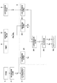
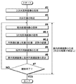
- Functional block diagram of the endoscope observation support system in the first embodiment of the present invention The flowchart showing the flow of the endoscopic observation support process in the first embodiment of the present invention.
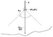
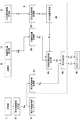
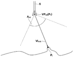
- the figure which represented typically an example of the virtual endoscope image in the 1st Embodiment of this invention Functional block diagram of the endoscope observation support system in the second embodiment of the present invention The flowchart showing the flow of the endoscopic observation support process in the second embodiment of the present invention.
- Functional block diagram of an endoscope observation support system according to third to seventh embodiments of the present invention The flowchart showing the flow of the endoscopic observation support processing in the third to seventh embodiments of the present invention.
- the figure which represented typically an example of the virtual endoscopic image in the 3rd Embodiment of this invention The figure which represented typically an example of the position of the treatment tool and the structure of interest, the viewpoint position of the virtual endoscope, the central line of sight, and the angle of view in the fourth embodiment of the present invention.
- FIG. 1 The figure which represented typically an example of the virtual endoscope image in the 5th Embodiment of this invention
- an example of the viewpoint position of a virtual endoscope, a center line-of-sight, and an angle of view in case another structure exists between an attention structure and a treatment tool was represented typically.
- Figure The figure which represented typically an example of the virtual endoscope image in the 6th Embodiment of this invention An example of the color template for changing the display color of a virtual endoscopic image according to the distance from the viewpoint to the surface of the anatomical structure in the abdominal cavity in the seventh embodiment of the present invention is schematically illustrated.
- Functional block diagram of an endoscope observation support system in the eighth embodiment of the present invention Flowchart showing the flow of endoscopic observation support processing in the eighth embodiment of the present invention.
- Functional block diagram of an endoscope observation support system in the ninth embodiment of the present invention The flowchart showing the flow of the endoscopic observation support process in the ninth embodiment of the present invention.
- the figure which represented typically the example of the positional relationship of a structure of interest, a structure requiring attention, and a treatment tool, and the field of view of a virtual endoscope in the ninth embodiment of the present invention The figure which represented typically an example of the virtual endoscopic image in the 9th Embodiment of this invention.
- Hardware configuration diagram of an endoscope observation support system according to a tenth embodiment of the present invention Functional block diagram of an endoscope observation support system according to the tenth embodiment of the present invention
- FIG. 10th embodiment of the present invention The figure which represented typically an example of the positional relationship of a treatment tool, an endoscope, and an attention structure, the viewpoint position of a virtual endoscope, a central line of sight, and a field angle in a 10th embodiment of the present invention.
- Functional block diagram of an endoscope observation support system in an eleventh embodiment of the present invention The flowchart showing the flow of the endoscopic observation support process in the eleventh embodiment of the present invention.
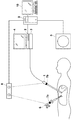
- FIG. 1 is a hardware configuration diagram showing an overview of an endoscope observation support system according to the first embodiment of the present invention. As shown in the figure, this system includes an endoscope 1, a digital processor 2, a light source device 3, a real endoscope image display 4, a modality 5, a treatment instrument 6, a treatment instrument marker 7a, a position sensor 8, An image processing workstation 9 and an image processing workstation display (hereinafter referred to as WS display) 10 are included.
- WS display image processing workstation display
- the endoscope 1 is a rigid endoscope for abdominal cavity and is inserted into the abdominal cavity of a subject.
- Light guided by an optical fiber from the light source device 3 is irradiated from the distal end portion of the endoscope 1, and an image in the abdominal cavity of the subject is obtained by the imaging optical system of the endoscope 1.
- the digital processor 2 converts the imaging signal obtained by the endoscope 1 into a digital image signal, corrects the image quality by digital signal processing such as white balance adjustment and shading correction, and then performs DICOM (Digital Imaging and Communications in Adds incidental information defined in the Medicine) standard and outputs actual endoscope image data (I RE ).
- DICOM Digital Imaging and Communications in Adds incidental information defined in the Medicine
- the output actual endoscope image data (I RE ) is transmitted to the image processing workstation 9 via the LAN according to a communication protocol compliant with the DICOM standard. Further, the digital processor 2 converts the actual endoscope image data (I RE ) into an analog signal and outputs the analog signal to the actual endoscope image display 4.
- the actual endoscope image display 4 includes the actual endoscope.
- An image (I RE ) is displayed. Since the acquisition of the imaging signal by the endoscope 1 is performed at a predetermined frame rate, the actual endoscope image (I RE ) is displayed as a moving image representing the abdominal cavity on the actual endoscope display 4. Furthermore, the endoscope 1 can also shoot still images according to user operations.
- the modality 5 is an apparatus that generates image data (V) of a three-dimensional medical image representing a region by imaging the region to be examined of the subject, and is a CT device here. Additional information defined by the DICOM standard is also added to the three-dimensional medical image data (V). The three-dimensional medical image data (V) is also transmitted to the image processing workstation 9 via the LAN according to a communication protocol compliant with the DICOM standard.
- the treatment instrument marker 7a and the position sensor 8 constitute a known three-dimensional position measuring apparatus.
- the treatment instrument marker 7 a is provided near the hand of the treatment instrument 6, and the optical position sensor 8 detects the three-dimensional position of the marker 7 a at a predetermined time interval. Since the treatment instrument marker 7a is composed of a plurality of marker pieces, the position sensor 8 can also detect the posture of the treatment tool 6 from the positional relationship of the marker pieces.
- the posture of the treatment instrument 6 is a vector representing the direction in which the treatment instrument is inserted, and coincides with the direction in which the treatment instrument advances straight. Further, the offset calculation, it is possible to calculate the three-dimensional position PS T of the distal end portion of the treatment instrument 6.
- the image processing workstation 9 is a computer having a well-known hardware configuration such as a CPU, a main storage device, an auxiliary storage device, an input / output interface, a communication interface, and a data bus, and includes an input device (pointing device, keyboard, etc.) WS display 10 is connected.
- the image processing workstation 9 is connected to the digital processor 2 and the modality 5 via a LAN and is connected to the position sensor 8 via a USB.
- the image processing workstation 9 is installed with a well-known operating system, various application software, and the like, and is also installed with an application for executing the endoscope observation support processing of the present invention. These software may be installed from a recording medium such as a CD-ROM, or may be installed after being downloaded from a storage device of a server connected via a network such as the Internet. Good.
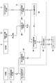
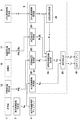
- FIG. 2 is a block diagram in which the endoscope observation support system according to the first embodiment of the present invention is divided at a functional level.
- the endoscope observation acquisition support system according to the first embodiment of the present invention includes an endoscope 1, an actual endoscope image forming unit 2, an actual endoscope image display 4, 3, and the like.
- the display control unit 25 is configured.
- the function of the treatment instrument position detection unit 11 is realized by the treatment instrument marker 7 a and the position sensor 8.
- the broken line frame indicates the image processing workstation 9, and the functions of the processing units in the broken line frame are realized by executing a predetermined program on the image processing workstation 9.
- the actual endoscopic image I RE the treatment tool detection position PS T , the treatment tool detection posture DS T , the treatment tool position P T , the treatment tool posture D T , the three-dimensional medical image V, and the virtual endoscope image I VE are These are data read / written to / from a predetermined memory area of the image processing workstation 9 by each processing unit in the broken line frame.
- a three-dimensional medical image V is formed by imaging the subject in the abdominal cavity by the three-dimensional medical image forming unit 5.
- the 3D medical image acquisition unit 23 acquires the 3D medical image V formed by the 3D medical image forming unit 5 (# 2).
- the real endoscope image forming unit 2 repeatedly forms and forms the real endoscopic image I RE by the endoscope 1 inserted into the body cavity at a predetermined frame rate.
- the actual endoscope image I RE thus displayed is displayed on the actual endoscope image display 4 in real time as a through moving image.
- treatment tool position detection unit 11 at predetermined time intervals, repeatedly detected in real time the position PS T and orientation DS T of the treatment instrument 6 which is inserted into a body cavity.
- the real endoscopic image acquisition unit 21 acquires the real endoscopic image I RE formed by the real endoscopic image forming unit 2 (# 4), and at almost the same timing as this.
- treatment tool position obtaining unit 22 obtains the detected treatment tool position detection PS T and treatment tool detected attitude DS T in treatment tool position detection unit 11, the obtained treatment tool position detection PS T and treatment tool detected attitude DS T and outputs the position and treatment tool position obtained by converting the position P T and the posture D T in the coordinate system of the three-dimensional medical image V (# 6).
- the endoscope angle-of-view acquisition unit 25 acquires the angle of view A E of the endoscope 1 from a predetermined memory area of the image processing workstation 9 (# 5).
- the virtual endoscopic image generation unit 24 receives the 3D medical image V acquired by the 3D medical image acquisition unit 23 as an input, uses the treatment instrument position PT acquired by the treatment instrument position acquisition unit 22 as a viewpoint, and performs a treatment.
- a virtual endoscopic image I VE is generated in which the tool posture D T , that is, the direction in which the treatment tool advances straight, is the line of sight at the center of the virtual endoscope field of view (# 8).
- the display control unit 25 uses the real endoscopic image I RE acquired by the real endoscopic image acquisition unit 21 and the virtual endoscopic image I VE generated by the virtual endoscopic image generation unit 24. It is displayed on the WS display 10 (# 10).
- the image processing workstation 9 unless an operation for instructing the end of observation is performed (# 12; No), a new real endoscopic image I RE is acquired (# 4), the treatment tool position PT at that time, and The treatment tool posture DT is acquired (# 6), the virtual endoscopic image I VE is generated (# 8), and the display of the real endoscopic image I RE and the virtual endoscopic image I VE is updated (# 10). Repeatedly. As a result, the WS display 10 realizes continuous display in which the real endoscopic image I RE and the virtual endoscopic image I VE are temporally synchronized. On the other hand, when an operation for instructing the end of observation is performed (# 12; Yes), the image processing workstation 9 ends the repeated processing from steps # 4 to # 10.
- the real endoscopic image acquisition unit 21 receives the real endoscopic image I RE through communication with the real endoscopic image forming unit (digital processor) 2 and stores a predetermined memory area of the image processing workstation 9.
- the real endoscopic image I RE is transferred from the real endoscopic image forming unit 2 based on a request from the real endoscopic image acquiring unit 21.
- Treatment tool position obtaining unit 22 and functions as a communication interface for obtaining a treatment tool position detection PS T and treatment tool detected attitude DS T through communication with treatment tool position detection unit 11, the acquired treatment tool position detection PS T and image processing by converting the treatment tool detected attitude DS T to have been treatment tool position P T and the treatment instrument attitude D T represented by coordinate values of the three-dimensional coordinate system of the three-dimensional medical image V from the three-dimensional coordinate system of the position sensor 8 And a function of storing in a predetermined memory area of the workstation 9.
- treatment tool position detection from the treatment tool position detection unit 11 in the request based from treatment tool position obtaining unit 22 PS T and treatment tool detected attitude DS T is obtained.
- the rotation amount of the coordinate axis is obtained in advance based on the correspondence relationship between the respective coordinate axes in the three-dimensional coordinate system of the position sensor and the respective coordinate axes in the three-dimensional coordinate system of the three-dimensional medical image V.
- the coordinate value in the three-dimensional coordinate system of the position sensor 8 of the position in the subject corresponding to the origin of the three-dimensional medical image V is measured in advance, and both coordinate axes are based on the coordinate value of the origin.
- treatment tool position detection PS T and treatment represented by three-dimensional coordinate system of the position sensor 8 it can be converted to immediately detect the posture DS T to be represented by coordinate values of the three-dimensional coordinate system of the three-dimensional medical image V the treatment tool position P T and the treatment instrument attitude D T.
- the three-dimensional medical image acquisition unit 23 has a communication interface function for receiving the three-dimensional medical image V from the three-dimensional medical image forming unit 5 and storing it in a predetermined memory area of the image processing workstation 9.
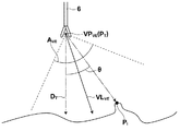
- the virtual endoscopic image generation unit 24 receives the three-dimensional medical image V as input, and as shown in FIG. 4A, the position PT of the treatment instrument 6 is set as the viewpoint position VP VE of the virtual endoscope, and
- the posture vector D T is a line-of-sight vector (hereinafter referred to as a center line-of-sight vector) VL VE that passes through the center of the visual field of the virtual endoscope, and the initial value A of the virtual endoscope angle of view given from the processing parameters of the program and the setting file VE0 is defined as the angle of view A VE, and within the range of the angle of view A VE , a plurality of radial lines of sight from the viewpoint position VP VE of the virtual endoscope are set, and each view is obtained by a volume rendering method using a known central projection.
- FIG. 4B schematically shows the generated virtual endoscopic image I VE .
- a color template whose color and transparency are defined in advance is used so that an image having substantially the same appearance as each intra-abdominal part represented in the actual endoscopic image I RE is obtained.
- the display control unit 28 generates a display screen in which the real endoscopic image I RE and the virtual endoscopic image I VE are arranged, and outputs the display screen to the WS display 10. As a result, a display screen in which the real endoscopic image I RE and the virtual endoscopic image I VE are arranged is displayed on the WS display 10.
- the virtual endoscope image generation unit 24 receives the three-dimensional medical image V as an input, and determines the position PT of the treatment tool 6 as the viewpoint position VP of the virtual endoscope. VE is generated, and a virtual endoscopic image I VE is generated in which the posture vector DT of the treatment instrument 6 is the central line-of-sight vector VL VE of the virtual endoscope, and the display control unit 28 and the virtual endoscopic image I RE The endoscopic image I VE is displayed on the WS display 10.
- the displayed virtual endoscopic image I VE is an image representing a state in which the treatment tool 6 is viewed straight from the position PT of the treatment tool 6 in a straight direction, that is, as if the treatment tool 6 is an endoscope. Since the image looks as if it is a mirror, it is possible to observe the inside of the body cavity from the viewpoint of the treatment instrument 6, and when combined with the actual endoscopic image I RE , the inside of the body cavity can be observed in many ways. It becomes possible.
- the virtual endoscope image I VE in which the visual field of the virtual endoscope is changed in real time by feedback of the result of the treatment instrument position detection unit 11 detecting the position of the treatment instrument 6 in real time is continuously displayed. Therefore, the movement state of the treatment tool 6 in the body cavity can be captured dynamically and more accurately.
- the real endoscope image forming unit 2 forms a real endoscopic image I RE representing the inside of the body cavity by real-time imaging by the endoscope 1, and the treatment used when generating the virtual endoscopic image I VE Since the real endoscopic image I RE formed at substantially the same timing as when the position of the tool 6 is detected is displayed, the real endoscopic image I RE and the virtual endoscopic image I VE are substantially the same. The state in the body cavity at the time is represented, and the real endoscopic image I RE and the virtual endoscopic image I VE are continuously displayed in time synchronization.
- the field of view of the real endoscopic image I RE changes in conjunction with operations such as movement and rotation of the endoscope 1, and in addition to the virtual interior in conjunction with operations such as movement and rotation of the treatment instrument 6.
- the field of view of the endoscopic image I VE also changes.
- the inside of the body cavity can be observed in real time and complementarily by the real endoscopic image I RE and the virtual endoscopic image I VE . .
- the virtual endoscopic image generation unit 24 uses a color template in which colors and transparency are defined in advance so that an image having substantially the same appearance as each intra-abdominal portion represented in the real endoscopic image I RE can be obtained. Since the virtual endoscopic image I VE is generated, when the real endoscopic image I RE and the virtual endoscopic image I VE are displayed side by side on the WS display 10 by the display control unit 25, both images are displayed. It is possible to observe without a sense of incongruity.
- the field of view of the endoscope 1 can be compensated in a wider range by making the initial value A VE0 of the view angle of the virtual endoscope wider than the view angle of the endoscope 1. preferable.
- the visual field of the virtual endoscope is determined only by the position P T and the posture D T of the treatment tool 6, notable structures in the body cavity are not necessarily included in the virtual endoscopic image I VE.
- the treatment tool 6 needs to be moved in order to confirm the positional relationship and the approach state between the treatment tool 6 and the structure to be noted.
- FIG. 5 is a functional block diagram of the endoscope observation support system according to the second embodiment of the present invention. As shown in the figure, a target position specifying unit 26 is added to the first embodiment. Yes.
- FIG. 6 is a flowchart showing the flow of the endoscopic observation support process in the second embodiment of the present invention.
- the three-dimensional medical image V is shown in FIG. Is acquired, the attention position specifying unit 26 accepts an operation for designating a target structure (for example, a surgical target part) in the body cavity represented by the three-dimensional medical image V acquired by the three-dimensional medical image acquisition unit 23.
- a target structure for example, a surgical target part
- the first embodiment Like the embodiment, acquisition of the real endoscopic image I RE is performed (# 4), where, as was appended to the right of the flowchart, treatment tool position detection unit 11 does not output the treatment tool detected attitude DS T since the outputs only treatment tool position detection PS T, step # 6 Then, the treatment instrument position acquisition unit 22 acquires only the treatment instrument position PT .
- the subsequent steps are the same as in the first embodiment.
- the attention position specifying unit 26 designates a target structure using a pointing device or a keyboard of the image processing workstation 9 in a cross-sectional image representing a predetermined cross-section generated from the three-dimensional medical image V by a known MPR method.
- a user interface that accepts an operation to perform is presented. For example, a pointing device, the target structure in the cross-sectional image is clicked, the target position identifying unit 26 identifies the position P I in a three-dimensional medical image V of the specified target structure by clicking,
- the data is stored in a predetermined memory area of the image processing workstation 9.
- a target structure a site to be operated, a point requiring attention at the time of surgery, and the like are designated according to the user's desire.
- treatment tool position detection unit 11 does not output the treatment tool detected attitude DS T
- also treatment tool position obtaining unit 22 does not output a treatment tool position D T.
- the virtual endoscope image generation unit 24 receives the three-dimensional medical image V as input, and as shown in FIG. 7A, the position PT of the treatment instrument 6 is set as the viewpoint position VP VE of the virtual endoscope, and A virtual endoscopic image I VE is generated in which the line of sight from the position P T toward the position P I of the target structure is the central line-of-sight vector VL VE of the virtual endoscope and the initial angle of view A VE0 is the angle of view A VE To do.
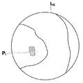
- the virtual endoscopic image I VE generated by the virtual endoscopic image generating unit 24 is the position P of the target structure as shown in FIG. 7B.
- I is represented at the center of the field of view, and the target structure is always included in the virtual endoscopic image I VE . Therefore, the positional relationship and the approach situation between the treatment tool 6 and the target structure can be grasped more reliably without operating the treatment tool 6.
- FIG. 8 is a functional block diagram of the endoscope observation support system according to the third to fifth embodiments of the present invention.
- the treatment instrument position detection unit 11 performs treatment in the second embodiment. to detect the tool detected attitude DS T, in which the treatment tool position obtaining unit 22 so as to obtain a treatment tool position D T.
- the posture DT is acquired together with the position P T of the treatment tool, and the position of the treatment tool is repeated while steps # 4 to # 10 are repeatedly performed.
- point PS T just not pose DS T also detected is different from the second embodiment.
- the virtual endoscope image generating unit 24 receives the three-dimensional medical image V as an input, and the position PT of the treatment tool 6 is set as the viewpoint position VP VE of the virtual endoscope as shown in FIG. 10A.
- the virtual vector having the angle of view A VE such that the posture vector D T of the treatment instrument 6 is the central visual axis vector VL VE of the virtual endoscope and the position P I of the structure of interest is included in the visual field of the virtual endoscope.
- An endoscopic image I VE is generated.
- the angle of view A VE of the virtual endoscope is, for example, a vector connecting the viewpoint position VP VE of the virtual endoscope and the position P I of the target structure and the central line-of-sight vector VL VE of the virtual endoscope. If the formed angle is ⁇ , the angle of view A VE of the virtual endoscope can be obtained by adding a constant to 2 ⁇ or multiplying by a predetermined coefficient greater than 1.
- the virtual endoscopic image I VE generated by the virtual endoscopic image generating unit 24 as shown in FIG. This represents the straight direction of the tool 6, and the target structure is included in the field of view.
- the fourth embodiment of the present invention is a modification of the visual field setting method of the virtual endoscope.
- the virtual endoscope image generating unit 24 receives the three-dimensional medical image V as an input, and the position PT of the treatment tool 6 is set as the viewpoint position VP VE of the virtual endoscope as shown in FIG. 11A.
- the line of sight from the position P T of the treatment tool 6 toward the position P I of the target structure is the central line-of-sight vector VL VE of the virtual endoscope, and the posture vector D T of the treatment tool 6 is included in the visual field of the virtual endoscope.
- the angle of view A VE of the virtual endoscope is, for example, when the angle formed by the posture vector DT and the central line-of-sight vector VL VE of the virtual endoscope is ⁇ , the angle of view A VE of the virtual endoscope is It can be obtained by adding a constant to 2 ⁇ or multiplying it by a predetermined coefficient larger than 1.
- the virtual endoscopic image generation unit 24 further calculates a position where the image information on the posture vector DT in the virtual endoscopic image I VE is projected, and at the calculated position, A marker AP T (star mark in FIG. 11B) indicating the straight direction of the treatment tool 6 is added.
- the virtual endoscopic image I VE generated by the virtual endoscopic image generating unit 24 has the structure of interest at the center of the visual field as shown in FIG. 11B.
- the object P I always exists, and the straight traveling direction of the treatment instrument 6 is shown in the image.
- the fifth embodiment of the present invention is also a modification of the field setting method of the virtual endoscope.
- the virtual endoscope image generation unit 24 receives the three-dimensional medical image V as an input, and the position PT of the treatment tool 6 is set as the viewpoint position VP VE of the virtual endoscope as shown in FIG. 12A.
- the visual line that bisects the angle ⁇ formed by the posture vector D T and the vector from the position P T of the treatment tool 6 toward the position P I of the target structure is defined as the central visual line vector VL VE of the virtual endoscope.
- a virtual endoscopic image I VE having an angle of view A VE such that the vector D T and the target structure are included in the visual field of the virtual endoscope is generated.
- the angle of view A VE of the virtual endoscope can be obtained, for example, by adding a constant to ⁇ or multiplying by a coefficient larger than a predetermined one.
- the virtual endoscopic image generation unit 24 further calculates the position where the image information on the posture vector DT in the virtual endoscopic image I VE is projected, and at the calculated position, A marker AP T (star symbol in FIG. 12B) indicating the straight direction of the treatment tool 6 is added.
- the virtual endoscopic image generation unit 24 displays the virtual endoscopic image in which both the straight direction of the treatment instrument 6 and the structure of interest are represented. Since the I VE is generated, it becomes possible to grasp both the positional relationship and the approach situation between the treatment tool 6 and the target structure and the direction in which the treatment tool 6 goes straight forward more easily and more reliably. Contributes to the prevention of mistakes in procedures and inspections.
- an initial value A VE0 that is wider than the angle of view of the endoscope 1 is determined in advance.
- the angle of view value obtained in step S is smaller than the initial value A VE0
- the angle of view A VE of the virtual endoscope is set to the image of the endoscope 1 by setting the initial value A VE0 as the angle of view A VE. It may be made wider than the corner.
- a predetermined error process processing interruption, change of posture of the treatment instrument 6 or the structure of the target structure is detected as an angle of view setting error.
- the target structure is assumed to be virtual.
- the angle of view AVE can be narrowed to set a large enlargement ratio. As a result, the field of view of the virtual endoscope is magnified and easy to observe.
- the position P I of the attention structures may be added to such markers in position on the virtual endoscopic image I VE, which is projected.
- the attention position specifying unit 24 extracts an area representing the entire structure of interest based on the position P I of the structure of interest designated by the user, and the virtual endoscope image generation unit 27 performs this attention. If the volume rendering is performed on the structure region using a color template different from that of other structures, the region of the target structure in the virtual endoscopic image I VE illustrated in FIG. It becomes possible to express in a highly discriminating manner, and the virtual endoscopic image I VE becomes easier to observe. Note that, for example, the technique described in Japanese Patent Application Laid-Open No. 2008-245719 proposed by the present applicant can be used for the extraction of the target structure region.
- this point accepts the setting of an arbitrary point P I in the target structure area (hereinafter, this point is referred to as a user set point), and uses information on the size of a possible lesion area defined in advance. Then, the three-dimensional existence range in which the lesion area can exist is determined, and the lesion is determined by using an area dividing method such as a graph cut method based on the set points and points outside the determined existence range. Regions can be extracted.
- the sixth embodiment of the present invention is a modification of the volume rendering process in the virtual endoscopic image generation unit 24, and includes the hardware configuration, functional blocks, and overall flow of the endoscope observation support system.
- the parts not shown in the present modification are the same as those in the third embodiment.
- FIG. 13A schematically illustrates an example of the positional relationship between the structure of interest and the treatment tool 6.
- the anatomical structure when another anatomical structure blocks the position PT of the treatment tool 6 that is the viewpoint of the virtual endoscopic image I VE and the target structure, the anatomical structure If the color template is defined so that the opacity of the structure becomes high, the target structure behind the anatomical structure is not drawn in the virtual endoscopic image I VE . Therefore, in the sixth embodiment of the present invention, the virtual endoscopic image generation unit 24 uses the color template in which the opacity is defined so as to display each part in the body cavity in a translucent manner. Generate VE .
- the generated virtual endoscopic image I VE has an anatomical structure between the position P I of the target structure and the treatment instrument position PT as schematically shown in FIG. 13B. is translucent, the position P I of the attention structures becomes visible at the back of the anatomical structure.
- the position P of the target structure is displayed. Even if an anatomical structure exists between I and the treatment instrument position PT , the entire structure area of interest can be represented in a highly visible manner.
- the seventh embodiment of the present invention is also a modification of the volume rendering process in the virtual endoscopic image generation unit 24, and the hardware configuration, functional block, and overall flow of the endoscope observation support system
- the parts not shown in the present modification are the same as those in the third embodiment.
- FIG. 14A schematically shows an example of a color template used in the seventh embodiment of the present invention.
- this color template is a virtual endoscope according to the distance from the position P T of the treatment instrument 6 (same as the viewpoint position P VE of the virtual endoscope) to the surface of the structure in the abdominal cavity. It is defined to change the color of the image VE .
- the virtual endoscopic image generation unit 24 sets the position where the pixel value abruptly changes above a predetermined threshold or the position where the pixel value exceeds a predetermined threshold on each line of sight during central projection.
- the distance from the position PT of the treatment tool 6 to the surface of the structure in the abdominal cavity is calculated, and this color template is used to virtually detect the surface of the detected structure.
- the generated virtual endoscopic image I VE is the treatment tool 6 for the surface of the structure.
- the color becomes lighter as the distance from the position P T becomes shorter, and the color becomes darker as the distance becomes longer. In this way, it becomes possible to compensate for the perspective of the virtual endoscopic image I VE that is difficult to capture the perspective, and the situation of the approach of the treatment instrument 6 to the intraabdominal structure (including the structure of interest) can be further improved. It becomes easy to grasp.
- the eighth embodiment of the present invention has a configuration in which a warning determination unit 27 is added to the third embodiment, and hardware for an endoscope observation support system.
- the configuration is the same as in the third embodiment.
- the warning determining unit 27 is a processing unit implemented in image processing workstation 9 calculates the distance between the position P I of the attention structure and position P T of treatment tool 6, the distance calculated When it is smaller than the predetermined threshold value, that is, when the treatment tool 6 is approaching the target structure to an unacceptable extent, the warning message WM is output.
- FIG. 16 is a flowchart showing the flow of endoscopic observation support processing in the eighth embodiment of the present invention.
- the actual endoscopic image in step # 10 of the third embodiment is shown in FIG.
- the warning determination unit 27 compares the distance with the threshold value (# 11.1), and if the distance is smaller than the threshold value (# 11.1; Yes) Then, the warning message WM is output, and the display control unit 25 superimposes and displays an arrow mark with a comment “approaching attention” in the vicinity of the position P I of the target structure, as illustrated in FIG.
- Such a warning display is particularly effective when the attention position specifying unit 26 designates a blood vessel or the like that causes major bleeding if the target structure is damaged during surgery.
- the method of outputting the warning message to the outside may be a method of outputting a warning sound or sound, in addition to the method of superimposing and displaying the virtual endoscope image I VE as described above, or the superimposition of the warning message.
- You may perform both a display and output, such as a warning sound.
- a risk determination table in which the risk corresponding to the distance is defined step by step is prepared in advance, and the warning determination unit 27 refers to the risk determination table based on the calculated distance.
- the risk value may be output as a warning message WM, and the display control unit 25 may display an icon or the like corresponding to the risk level on the WS display 10.
- the ninth embodiment of the present invention has a configuration in which a cautionary structure detection unit 28 is added to the first embodiment, and an endoscope observation support system.
- the hardware configuration is the same as that of the third embodiment.
- the cautionary structure detection unit 28 is a processing unit mounted on the image processing workstation 9 and detects the cautionary structure region RA by a known image recognition method using the three-dimensional medical image V as an input.
- FIG. 20A schematically illustrates an example of the positional relationship among the treatment tool 6, the target structure, and the structure requiring attention.
- the cautionary structure detection unit 28 detects a vascular region RA to be noted on the back side of the abdominal wall by performing a known blood vessel extraction process.
- Figure 19 is a flow chart showing the flow of endoscopic observation support process in the ninth embodiment of the present invention, as shown in FIG., The target position P I in step # 3 of the third embodiment
- the caution structure detection unit 28 detects the caution structure area RA (# 3.1).
- the virtual endoscopic image generation unit 24 generates a virtual endoscopic image I VE using a color template defined so that the structure area RA requiring attention is visible.
- FIG. 20B schematically shows an example of the generated virtual endoscopic image IVE .
- the virtual endoscopic image I VE shown in the figure is generated by using a color template in which the pixels representing the abdominal wall are translucent and the color and opacity are defined so that the pixels representing the blood vessels are highly visible It has been done. Thereby, the visibility of the structure requiring attention is increased, which contributes to prevention of erroneous operation of the endoscope 1 and the treatment instrument 6.
- the caution structure detection unit 28 may detect the caution structure area RA by a user's manual operation.
- a marker such as an arrow or an annotation such as a text comment may be superimposed and displayed on the structure area RA requiring attention.
- the tenth embodiment of the present invention generates a virtual endoscopic image in which the posture structure of the target structure, the endoscope 1 and the treatment instrument 6 are all included in the visual field. As shown in the hardware configuration diagram, an endoscope marker 7b is added to the first embodiment shown in FIG.
- the endoscope marker 7 b constitutes a three-dimensional position measuring device together with the position sensor 8, and is provided in the vicinity of the hand of the endoscope 1. , three-dimensional positions of markers 7b at predetermined time intervals are detected by the offset calculation, it is possible to calculate the three-dimensional position PS E of the distal end of the endoscope 1.
- FIG. 22 is a functional block diagram of the tenth embodiment of the present invention, in which an endoscope position detection unit 12 and an endoscope position acquisition unit 29 are added to the third embodiment shown in FIG. It has a configuration.
- the function of the endoscope position detector 12 is realized by the endoscope marker 7b and the position sensor 8 of FIG.
- the endoscope position P E is the respective processing units in the broken line frame are data written into and read out from a predetermined memory area of image processing workstation 9.
- FIG. 23 is a flowchart showing the flow of endoscopic observation support processing in the tenth embodiment of the present invention.
- FIG. 23 shows the intraperitoneal cavity of a subject using the endoscope 1.
- the real endoscope image forming unit 2 repeatedly forms the real endoscopic image I RE and the treatment instrument position detection unit 11 detects the position PS of the treatment instrument 6. not only detect the T and posture DS T, endoscope position detection unit 12, at predetermined time intervals, to detect in real time repeated position PS E of the endoscope 1 inserted into a body cavity.
- the endoscope position obtaining unit 29 obtains the endoscope position detection PS E detected by endoscope position detection unit 12 , and outputs the obtained endoscope position PS E to 3-dimensional medical image V of the coordinate system the endoscope obtained by converting the position in the position P E (# 7).
- virtual endoscopic image generation unit 24 when generating the virtual endoscopic image I VE, based on the endoscope position P E obtained by endoscope position obtaining unit 29, a virtual endoscopy generating a virtual endoscopic image I VE expressed in an identifiable manner that there is the endoscope 1 at a position corresponding to the endoscope position P E in the image I VE (# 7).
- the subsequent processing flow (# 10 to # 12) is the same as in the third embodiment.
- the endoscope position obtaining unit 29 like the treatment tool position obtaining unit 22, and functions as a communication interface for obtaining an endoscope position detection PS E through communication with endoscope position detection unit 12, among the acquired predetermined viewing mirror detection position PS E to convert the endoscopic position P E expressed by coordinate values of the three-dimensional coordinate system of the three-dimensional medical image V from the three-dimensional coordinate system of the position sensor 8 image processing workstation 9 And a function of storing in the memory area.
- the virtual endoscope image generation unit 24 receives the three-dimensional medical image V as input, and the position PT of the treatment instrument 6 is set as the viewpoint position VP VE of the virtual endoscope as schematically shown in FIG. 24A.
- the posture vector D T of the treatment instrument 6 and with the center line of sight vector VL VE of the virtual endoscope, the position P I of the attention structures, and the position P E of the endoscope 1 is contained within the field of view of the virtual endoscopic A virtual endoscope pre-image having such a view angle A VE is generated.
- the angle of view A VE of the virtual endoscope is, for example, a vector connecting the viewpoint position VP VE of the virtual endoscope and the position P I of the target structure and the central line-of-sight vector VL VE of the virtual endoscope. 1 an angle alpha, when the angle between the center line of sight vector VL VE vector and virtual endoscopic connecting the viewpoint position VP VE and the endoscope position P E in virtual endoscopic and alpha 2, virtual endoscopy
- the angle of view A VE of the mirror can be obtained by adding a constant to the larger value of 2 ⁇ 1 and 2 ⁇ 2 or multiplying by a predetermined coefficient larger than 1.
- the angle of view A VE is determined based on 2 ⁇ 2 .
- the virtual endoscope image generation unit 24 generates an endoscope shape image M E representing a state in which the endoscope 1 is present at the endoscope position P E.
- the endoscope shape image M E is based on the image representing the shape of the endoscope 1 stored in the database and the endoscope position P E as described in Patent Document 2 above. Generated.
- virtual endoscopic image generation unit 24 by combining the virtual endoscopic preliminary image and the endoscope shape image M E by a known method such as alpha blending, and generates a virtual endoscopic image I VE .
- the virtual endoscopic image I VE may be generated by superimposing annotations such as markers and text comments.
- FIG. 24B is an example of a virtual endoscopic image I VE generated by the present embodiment are those showing schematically, as shown in FIG., The endoscope position within the endoscope in an image I VE virtual An endoscope shape image M E is superimposed at a position corresponding to P E.
- generation position P I not only the position P E also virtual endoscopic image I VE, which is included in the visual field of the endoscope 1 of the target structure is Therefore, it is possible to reliably grasp not only the treatment tool 6 and the target structure but also the mutual positional relationship and approach state including the endoscope 1.
- the virtual endoscope image I VE in which the field of view and image content of the virtual endoscope are changed in real time by feedback of the result of the endoscope position detection unit 12 detecting the position of the endoscope 1 in real time. are continuously displayed, so that not only the treatment instrument 6 and the target structure but also the mutual positional relationship and approach situation including the endoscope 1 can be dynamically and accurately captured.
- the real endoscopic image forming unit 2 forms a real endoscopic image I RE representing the inside of the body cavity by real-time imaging by the endoscope 1 and is used when the virtual endoscopic image I VE is generated. Since the real endoscopic image I RE formed at almost the same timing as the positions of the endoscope 1 and the treatment instrument 6 are detected, the real endoscopic image I RE and the virtual endoscopic image I VE are displayed. Indicates a state in the body cavity at substantially the same time, and the real endoscopic image I RE and the virtual endoscopic image I VE are continuously displayed in time synchronization.
- the field of view of the actual endoscopic image I RE changes in conjunction with operations such as movement and rotation of the endoscope 1, and also in conjunction with the operation of the endoscope 1 as well as the treatment instrument 6.
- the field of view and image content of the virtual endoscopic image IVE also change.
- the real endoscopic image I RE and the virtual endoscopic image I VE can further observe the inside of the body cavity in real time and complementarily. Become.
- the eleventh embodiment of the present invention forms and acquires a three-dimensional medical image V in real time during observation using an endoscope.
- the hardware configuration of the tenth embodiment see FIG. 21).
- the treatment instrument marker 7a, the endoscope marker 7b, and the position sensor 8 are unnecessary.
- FIG. 25 is a functional block diagram of the endoscope observation support system according to the eleventh embodiment of the present invention.
- an endoscope / The processing tool position recognition unit 30 is added. That is, the endoscope / treatment instrument position recognition unit 30 corresponds to the position detection means of the present invention.
- the endoscope / treatment instrument position recognizing unit 30 is a processing unit mounted on the image processing workstation 9.
- the endoscope / treatment instrument position recognizing unit 30 receives the three-dimensional medical image V as an input and performs a known pattern recognition process on the inner part of the three-dimensional medical image V.
- a region representing the endoscope 1 or the treatment tool 6 is extracted, and the endoscope position P E, the treatment tool position P T , and the treatment tool posture D T are recognized.
- FIG. 26 is a flowchart showing the flow of endoscopic observation support processing in the eleventh embodiment of the present invention.
- the three-dimensional medical image V is acquired by the three-dimensional medical image acquisition unit 24 (# 6.1).
- the endoscope / treatment tool position recognition unit 30 recognizes the endoscope position P E, the treatment tool position P T , and the treatment tool posture D T based on the three-dimensional medical image V acquired by the three-dimensional medical image acquisition unit 24. (# 6.2).
- the virtual endoscopic image generation unit 24 is defined so that the region representing the endoscope 1 extracted by the endoscope / treatment instrument position recognition unit 30 is displayed in a predetermined color.
- a virtual endoscopic image I VE is generated using the obtained color template. Therefore, it is not necessary to generate a shape image of the endoscope 1 as in the tenth embodiment.
- the acquired three-dimensional medical image V is substantially the same time point as the real endoscopic image I RE. Therefore, the situation inside the abdominal cavity is more accurately reproduced in real time than when the three-dimensional medical image V acquired before the observation under the endoscope is used.
- a virtual endoscopic image I VE is generated.
- an ultrasonic diagnostic apparatus as the modality 5 in order to reduce the exposure dose of the subject.
- the modality 5 and the image processing workstation 9 are directly connected in the hardware configuration of FIGS. 1 and 21, but the image storage server is connected on the LAN.
- the three-dimensional medical image V formed by the modality 5 is temporarily stored in the database of the image storage server, and in response to a request from the image processing workstation 9, the three-dimensional medical image V is transferred from the image storage server to the image processing workstation 9.
- the medical image V may be transferred.
- the endoscope 1 may be a flexible endoscope or a capsule endoscope instead of a rigid endoscope.
- the modality 5 may use an MRI apparatus or the like in addition to the above CT apparatus and ultrasonic diagnostic apparatus.
- the WS display 10 may be a display corresponding to a known stereoscopic display, and may display the virtual endoscopic image IVE as a stereoscopic image.
- the virtual endoscopic image generation unit 24 uses the left and right eyes from the viewpoint position VP VE.
- the position of each eye shifted by the amount of parallax is set, and a virtual endoscopic parallax image for the left and right eyes is generated by central projection with the set position of each eye as the viewpoint, and the display control unit 25 displays the virtual endoscope parallax image for the left eye on the display pixel for the left eye of the WS display 10, and the virtual endoscope parallax image for the right eye on the display pixel for the right eye of the WS display 10. What is necessary is just to control to display.
- the treatment instrument position detection unit 11 and the endoscope instrument position detection unit 12 may be magnetic, or may be a gyroscope or a rotary encoder as described in Patent Document 2 above. .
- observation site may be another site of the subject suitable for observation under the endoscope, such as in the chest cavity, not in the abdominal cavity.
- the virtual endoscopic image generation unit 24 uses the virtual endoscope image generation unit 24 to generate the virtual endoscopic image I RE in the cycle in which the real endoscopic image forming unit 2 forms the real endoscopic image I RE.
- the I VE is shorter than the cycle in which the VE is generated, it is assumed that the image is received on a request basis from the real endoscope image acquisition unit 21 in consideration of the communication load.
- the actual endoscope image acquisition unit 21 may receive all of the formed actual endoscope image IE .
- the display control unit 25 is asynchronous with the generation timing of the virtual endoscopic image I VE by the virtual endoscopic image generation unit 24 and every time the real endoscopic image I RE is received, the real display of the WS display 10 is performed.
- the display of the endoscopic image I RE may be updated.
- Treatment tool position obtaining unit 22 leave receive all treatment tool position PS T and posture DS T detected by treatment tool position detection unit 11 at predetermined time intervals, the process of step # 4 in FIG. 3 or the like may be the only treatment tool position PS T and orientation DS T received at timing that is called to output the converted to the treatment tool position P E and the posture D T by the latter coordinate transformation function. The same applies to the endoscope position acquisition unit 29.
- the coordinate transformation performed by the treatment instrument position acquisition unit 22 and the endoscope position acquisition unit 29 may be performed by the virtual endoscope image generation unit 24.
- the attention position specifying unit 26 may automatically specify the attention position using a known image recognition technique (such as a blood vessel or organ extraction method or an abnormal shadow detection method).
- a known image recognition technique such as a blood vessel or organ extraction method or an abnormal shadow detection method.
- the virtual endoscopic image generation unit 24 further generates a virtual endoscopic image having a plurality of positions of interest as viewpoints, such as a surgical target site, a blood vessel requiring attention, an organ requiring attention, and a treatment tool. May be.
Landscapes
- Engineering & Computer Science (AREA)
- Health & Medical Sciences (AREA)
- Life Sciences & Earth Sciences (AREA)
- Surgery (AREA)
- Medical Informatics (AREA)
- Physics & Mathematics (AREA)
- Nuclear Medicine, Radiotherapy & Molecular Imaging (AREA)
- Molecular Biology (AREA)
- General Health & Medical Sciences (AREA)
- Animal Behavior & Ethology (AREA)
- Public Health (AREA)
- Biomedical Technology (AREA)
- Heart & Thoracic Surgery (AREA)
- Veterinary Medicine (AREA)
- Optics & Photonics (AREA)
- Software Systems (AREA)
- Pathology (AREA)
- Biophysics (AREA)
- Radiology & Medical Imaging (AREA)
- Theoretical Computer Science (AREA)
- Radar, Positioning & Navigation (AREA)
- Remote Sensing (AREA)
- Computer Graphics (AREA)
- Computer Hardware Design (AREA)
- General Engineering & Computer Science (AREA)
- General Physics & Mathematics (AREA)
- Signal Processing (AREA)
- High Energy & Nuclear Physics (AREA)
- Robotics (AREA)
- Endoscopes (AREA)
- Instruments For Viewing The Inside Of Hollow Bodies (AREA)
Abstract
【課題】被検体の体腔内に挿入された内視鏡下での体腔内の観察の際に、手術対象部位等の注目箇所と処置具との位置関係や相互の接近状況をより確実に把握する。 【解決手段】仮想内視鏡画像生成部(24)が、3次元医用画像形成部(5)によって形成された3次元医用画像を入力として、処置具位置検出部(11)でリアルタイムに検出された処置具の位置に対応する3次元医用画像中の位置から見た体腔内を表す仮想内視鏡画像を生成する。生成された仮想内視鏡画像はWSディスプレイ(10)に表示される。
Description
本発明は、被検体の体腔内に挿入された内視鏡下での手術や検査等における、内視鏡観察を支援する技術に関するものであり、特に、被検体の体腔内を表す仮想内視鏡画像を用いて内視鏡観察を支援する技術に関するものである。
近年、腹腔鏡手術や胸腔鏡手術等の内視鏡下で行われる手術が注目されている。この内視鏡手術では、開腹や開胸等を行うことなく、内視鏡と処置具を刺入するための数センチ程度の穴を2、3個開けるだけで済むので、患者の負担が極めて小さいというメリットがある。一方で、内視鏡の限られた視野で手術を実施することは技術的難易度が高く、執刀を行う医師は熟練を要する。もし患者の血管や臓器を誤って傷つけてしまい、出血してしまった場合には、開腹、開胸等を伴う従来の手法による手術に移行せざるを得ない。
一方、CT等での撮影によって得られた3次元ボリューム画像から内視鏡と類似した画像を生成する仮想内視鏡技術が知られている。この技術は、特に大腸の腫瘍を発見するために、内視鏡検査をすることなくCT撮影のみで腫瘍を発見する方法として北米で普及している。
そして、仮想内視鏡画像を用いて内視鏡手術を支援する技術が提案されている。
例えば、特許文献1には、内視鏡の位置をセンサで検出し、検出位置を視点とし、内視鏡よりも広い画角を有する仮想内視鏡画像を生成し、内視鏡撮影で得られた実内視鏡画像と仮想内視鏡画像とを重畳表示する装置が記載されている。
また、特許文献2には、内視鏡の位置をリアルタイムに検出し、内視鏡と同じ視野を有し、視野内の血管配置が視覚化された仮想内視鏡画像を生成するとともに、内視鏡下での手術に用いられる処置具の位置をリアルタイムに検出し、仮想内視鏡画像中での処置具の位置に処置具を表す画像を合成した画像を生成し、合成画像と実内視鏡画像を表示する装置が記載されている。
しかしながら、これらの文献に記載された手法では、内視鏡の狭い視野を仮想内視鏡画像によって補うことはできるものの、仮想内視鏡画像は実内視鏡画像と同じ視点、同じ観察方向の画像であるから、手術対象部位等の注目箇所と処置具と内視鏡との位置関係によっては、仮想内視鏡画像や実内視鏡画像中に注目箇所や処置具が表示されない可能性があり、これらの位置関係が把握できないこともありうる。
また、内視鏡画像では遠近感を把握しづらいので、これらの文献に記載された手法による仮想内視鏡画像や実内視鏡画像では、処置具の注目箇所への接近状況を把握することが困難となることもありうる。
本発明は上記事情に鑑みてなされたものであり、被検体の体腔内に挿入された内視鏡下での体腔内の観察の際に、手術対象部位等の注目箇所と処置具との位置関係や注目箇所に対する処置具の接近状況をより確実に把握可能なシステムおよび方法、並びに、装置およびプログラムを提供することを目的とするものである。
本発明の内視鏡観察支援システムは、被検体の体腔内を表す3次元医用画像を形成する3次元医用画像形成手段と、前記体腔内に挿入された処置具の位置をリアルタイムに検出する処置具位置検出手段と、前記3次元医用画像を入力として、前記検出された処置具の位置に対応する前記3次元医用画像中の位置である対応処置具位置から見た前記体腔内を表す仮想内視鏡画像を生成する仮想内視鏡画像生成手段と、前記仮想内視鏡画像を表示する表示手段とを設けたことを特徴とする。
本発明の内視鏡観察支援方法は、被検体の体腔内を表す3次元医用画像を形成するステップと、前記体腔内に挿入された処置具の位置をリアルタイムに検出するステップと、前記3次元医用画像を入力として、前記検出された処置具の位置に対応する前記3次元医用画像中の位置である対応処置具位置から見た前記体腔内を表す仮想内視鏡画像を生成するステップと、前記仮想内視鏡画像を表示するステップとを有することを特徴とすることを特徴とする。
本発明の内視鏡観察支援装置は、被検体の体腔内を表す3次元医用画像を取得する3次元医用画像取得手段と、位置検出手段によってリアルタイムに検出された前記体腔内に挿入された処置具の位置を取得する処置具位置取得手段と、前記3次元医用画像を入力として、前記取得された処置具の位置に対応する前記3次元医用画像中の位置である対応処置具位置から見た前記体腔内を表す仮想内視鏡画像を生成する仮想内視鏡画像生成手段と、前記仮想内視鏡画像を表示手段に表示させる表示制御手段とを設けたことを特徴とする。
本発明の内視鏡観察支援プログラムは、コンピュータに、被検体の体腔内を表す3次元医用画像を取得するステップと、位置検出手段によってリアルタイムに検出された前記体腔内に挿入された処置具の位置を取得するステップと、前記3次元医用画像を入力として、前記取得された処置具の位置に対応する前記3次元医用画像中の位置である対応処置具位置から見た前記体腔内を表す仮想内視鏡画像を生成するステップと、前記仮想内視鏡画像を表示手段に表示させるステップとを実行させることを特徴とする。
以下、本発明の詳細について説明する。
本発明において、処置具の位置と同時に処置具が直進する向きも検出するようにし、検出された処置具が直進する向きに対応する3次元医用画像中での向きを有する対応処置具位置からの視線(処置具視線)上の画像情報が投影された仮想内視鏡画像を生成するようにしてもよい。このような仮想内視鏡画像の具体例としては、処置具視線を仮想内視鏡画像の視野の中心における視線(中心視線)とした仮想内視鏡画像が挙げられる。また、処置具視線上の画像情報が投影された仮想内視鏡画像中の位置を識別可能な態様で表すようにしてもよい。
また、本発明において、体腔内の(第1の)注目構造物の3次元医用画像中での位置を特定するようにし、特定された(第1の)注目位置が仮想内視鏡画像における視野内に含まれる仮想内視鏡画像を生成するようにしてもよい。このような仮想内視鏡画像の具体例としては、対応処置具位置から、特定された(第1の)注目位置に向かう視線を仮想内視鏡画像の中心視線とした仮想内視鏡画像が挙げられる。また、(第1の)注目構造物のうちの少なくとも(第1の)注目位置を識別可能な態様で表すようにしてもよい。
ここで、「(第1の)注目構造物」の具体例としては、内視鏡下での手術対象部位や、手術において注意を有する解剖学的構造物、すなわち、血管や、臓器、腫瘍等が挙げられる。これらの(第1の)注目構造物の位置の具体的な特定方法は、公知の画像認識技術を用いた自動的方法、ユーザの手動操作による方法、両者を組み合わせた方法のいずれであってもよい。
さらに、本発明において、対応処置具位置と(第1の)注目構造物とが所定の基準を満たす程度に接近している場合には警告を提示するようにしてもよい。警告は仮想内視鏡画像中等に視覚的に提示してもよいし、他の感覚器に訴える方法で提示してもよい。
さらにまた、本発明において、3次元医用画像中の体腔内の第2の注目構造物を検出するようにし、検出された第2の注目構造物が識別可能な態様の仮想内視鏡画像を生成するようにしてもよい。ここで、「第2の注目構造物」の具体例としては、第1の注目構造物と同様のものが挙げられる。したがって、例えば、第1の構造物は内視鏡下での手術対象部位とし、第2の注目構造物は手術において注意を有する解剖学的構造物とするか、あるいは、その逆とすることが考えられる。
また、本発明において、体腔内に挿入された内視鏡の位置を検出するようにし、検出された内視鏡の位置に対応する3次元医用画像中の位置(対応内視鏡位置)が仮想内視鏡画像における視野内に含まれ、かつ、対応内視鏡位置が識別可能な態様で表された仮想内視鏡画像を生成するようにしてもよい。
ここで、3次元医用画像が内視鏡下での観察前に取得されたものの場合には、3次元医用画像の撮像・取得時には、被検体の体腔内に内視鏡はまだ挿入されていないので、仮想内視鏡画像生成時に、位置検出手段によって検出された位置に対応する仮想内視鏡画像中の位置に、内視鏡を表すマーカー等を合成すればよい。一方、3次元医用画像が内視鏡下での観察中にリアルタイムに取得されたものであり、その画像中に内視鏡が表されている場合には、仮想内視鏡画像中にもその内視鏡が描出されるように仮想内視鏡画像を生成すればよい。
さらに、本発明において、内視鏡によるリアルタイムの撮像によって体腔内を表す実内視鏡画像を形成するようにし、仮想内視鏡画像とともに、仮想内視鏡画像の生成時に用いられた処置具の位置が検出されたのとほぼ同じタイミングで形成された実内視鏡画像をさらに表示するようにしてもよい。これにより、内視鏡での撮像によりリアルタイムに形成された実内視鏡画像と、実内視鏡画像の形成とほぼ同じタイミングで位置検出手段によってリアルタイムに検出された処置具の位置から見た仮想内視鏡画像とが表示される。
また、処置具の位置の検出に応じて仮想内視鏡画像の生成を繰り返し行えば、処置具の移動に応じて、実内視鏡画像も仮想内視鏡画像もリアルタイムに更新される。
なお、実内視鏡画像と仮想内視鏡画像の表示は、1つの表示装置に行ってもよいし、複数の表示装置に別々に行ってもよい。複数の表示装置は、両画像を同時に観察可能なように物理的に同じ場所に並べられて設置されていてもよいし、両画像を個別に観察するために物理的に離れた場所に設置されていてもよい。
また、「(第1の)注目位置が仮想内視鏡画像における視野内に含まれる」や「対応内視鏡位置が仮想内視鏡画像における視野内に含まれ(る)」とは、視点(対応処置具位置)から(第1の)注目位置や対応内視鏡位置に向かう視線上の画像情報が仮想内視鏡画像に反映されていればよく、例えば、処置具と(第1の)注目構造物または内視鏡との間に、臓器や血管、ヒダ等の構造物がある場合等には、仮想内視鏡画像中に内視鏡または(第1の)注目構造物が必ずしも表されていなくてもよい。
「仮想内視鏡画像」の生成の際、対応処置具位置から体腔内の構造物の表面までの距離を仮想内視鏡画像の画素値の決定要素として用いてもよい。また、実内視鏡画像に表された体腔内各部とほぼ同じ外観の仮想内視鏡画像が得られるように定義されたカラーテンプレートを用いてもよい。ただし、このカラーテンプレートには、例えば、体腔内各部の色が実内視鏡画像とほぼ同じになるように定義されたものとしつつ、体腔内各部を必要に応じて半透明化し、実内視鏡画像では前方の遮蔽物等により観察することのできない後方の構造物を視認できるように定義されたものも含まれる。
本発明において、3次元医用画像の形成・取得を内視鏡下での観察中に行う場合には、リアルタイムでその取得を行うようにしてもよい。その際、取得された3次元医用画像に対する画像認識処理により、内視鏡または処置具の位置を検出するようにしてもよい。
本発明では、被検体の体腔内を表す3次元医用画像を入力として、リアルタイムに検出された体腔内に挿入された処置具の位置に対応する3次元医用画像中の対応位置から見た体腔内を表す仮想内視鏡画像が生成され、表示される。ここで、表示される仮想内視鏡画像は、あたかも処置具が内視鏡であるかのような画像となるので、処置具の視点から体腔内を観察することが可能になり、実際の内視鏡による画像とあわせれば、多面的に体腔内を観察することが可能になる。したがって、注目箇所と処置具の位置関係をより確実に把握できるようになる。また、処置具の注目箇所に対する接近状況をより確実に把握できるようにもなる。これらにより、手術や検査等における手技のミス等の防止に資する。
また、このとき、処置具の位置をリアルタイムに検出した結果のフィードバックによって仮想内視鏡の視点がリアルタイムに変更された仮想内視鏡画像が連続的に表示されるので、注目構造物への処置具の接近状況を、動的に、より的確に捉えることが可能になる。
さらに、内視鏡によるリアルタイムの撮像によって体腔内を表す実内視鏡画像を形成するようにし、仮想内視鏡画像とともに、仮想内視鏡画像の生成時に用いられた内視鏡の位置および姿勢が検出されたのとほぼ同じタイミングで形成された実内視鏡画像を表示するようにすれば、表示される実内視鏡画像と仮想内視鏡画像とは、ほぼ同じ時点での体腔内の状態が表されたものとなり、実内視鏡画像と仮想内視鏡画像とが時間的同期を取って連続的に表示される。また、このとき、処置具の位置の検出に応じて仮想内視鏡画像の生成を繰り返し行えば、実内視鏡画像も仮想内視鏡画像もリアルタイムに更新される。すなわち、内視鏡の移動や回転等の操作に連動して実内視鏡画像の視野が変化するとともに、処置具の移動等の操作に連動して仮想内視鏡画像の視野も変化させることができる。このように、実内視鏡画像と仮想内視鏡画像によって相互補完的に体腔内を観察することが可能になる。
以下、本発明の実施の形態となる内視鏡観察支援システムについて説明する。
図1は、本発明の第1の実施形態となる内視鏡観察支援システムの概要を示すハードウェア構成図である。図に示したように、このシステムは、内視鏡1、デジタルプロセッサ2、光源装置3、実内視鏡画像用ディスプレイ4、モダリティ5、処置具6、処置具用マーカー7a、位置センサ8、画像処理ワークステーション9、画像処理ワークステーション用ディスプレイ(以下、WSディスプレイ)10から構成されている。
本実施形態では、内視鏡1は腹腔用の硬性鏡であり、被検体の腹腔内に挿入される。光源装置3から光ファイバーで導かれた光が内視鏡1の先端部から照射され、内視鏡1の撮像光学系により被検体の腹腔内の画像が得られる。デジタルプロセッサ2は、内視鏡1で得られた撮像信号をデジタル画像信号に変換し、ホワイトバランス調整やシェーディング補正等のデジタル信号処理によって画質の補正を行った後、DICOM(Digital Imaging and Communications in Medicine)規格で規定された付帯情報を付加して、実内視鏡画像データ(IRE)を出力する。出力された実内視鏡画像データ(IRE)は、DICOM規格に準拠した通信プロトコルに従って、LAN経由で画像処理ワークステーション9に送信される。また、デジタルプロセッサ2は、実内視鏡画像データ(IRE)をアナログ信号に変換して実内視鏡画像用ディスプレイ4に出力し、実内視鏡画像用ディスプレイ4には実内視鏡画像(IRE)が表示される。内視鏡1での撮像信号の取得は所定のフレームレートで行われるので、実内視鏡用ディスプレイ4では、実内視鏡画像(IRE)が腹腔内を表す動画として表示される。さらに、内視鏡1では、ユーザの操作に応じて静止画撮影も可能である。
モダリティ5は、被検体の検査対象部位を撮影することにより、その部位を表す3次元医用画像の画像データ(V)を生成する装置であり、ここではCT装置とする。この3次元医用画像データ(V)にもDICOM規格で規定された付帯情報が付加されている。また、3次元医用画像データ(V)も、DICOM規格に準拠した通信プロトコルに従って、LAN経由で画像処理ワークステーション9に送信される。
処置具用マーカー7aおよび位置センサ8は公知の3次元位置計測装置を構成する。処置具用マーカー7aは、処置具6の手元付近に設けられており、光学式の位置センサ8によって、所定の時間間隔でマーカー7aの3次元位置が検出される。処置具用マーカー7aは複数のマーカー片から構成されているので、位置センサ8は、各マーカー片の位置関係から処置具6の姿勢も検出可能である。ここで、処置具6の姿勢は、処置具が挿入された向きを表すベクトルであり、処置具の直進する向きと一致する。また、オフセット計算によって、処置具6の先端部の3次元位置PSTを算出することができる。位置センサ8は、算出された処置具6の3次元位置データPST、および、3次元姿勢データDSTを、USBインターフェースを介して画像処理ワークステーション9に送信する。
画像処理ワークステーション9は、CPU、主記憶装置、補助記憶装置、入出力インターフェース、通信インターフェース、データバス等の周知のハードウェア構成を備えたコンピュータであり、入力装置(ポインティングデバイス、キーボード等)や、WSディスプレイ10が接続されている。また、画像処理ワークステーション9は、デジタルプロセッサ2やモダリティ5とはLAN接続されており、位置センサ8とはUSB接続されている。さらに、画像処理ワークステーション9は、周知のオペレーティングシステムや各種アプリケーション・ソフトウェア等がインストールされたものであり、本発明の内視鏡観察支援処理を実行させるためのアプリケーションもインストールされている。これらのソフトウェアは、CD-ROM等の記録媒体からインストールされたものであってもよいし、インターネット等のネットワーク経由で接続されたサーバの記憶装置からダウンロードされた後にインストールされたものであってもよい。
図2は、本発明の第1の実施形態における内視鏡観察支援システムを機能レベルで分割したブロック図である。図に示したように、本発明の第1の実施形態となる内視鏡観察得支援システムは、内視鏡1、実内視鏡画像形成部2、実内視鏡画像用ディスプレイ4、3次元医用画像形成部5、WSディスプレイ10、処置具位置検出部11、実内視鏡画像取得部21、処置具位置取得部22、3次元医用画像取得部23、仮想内視鏡画像生成部24、表示制御部25から構成されている。なお、図1に示したハードウェア機器と図2に示した各機能ブロックとが概ね1対1に対応する場合には同じ符号を付している。すなわち、実内視鏡画像形成部2の機能は図1のデジタルプロセッサによって実現され、3次元医用画像形成部5の機能は図1のモダリティによって実現される。一方、処置具位置検出部11の機能は、処置具用マーカー7aおよび位置センサ8によって実現される。また、破線枠は画像処理ワークステーション9を示しており、破線枠内の各処理部の機能は、画像処理ワークステーション9で所定のプログラムを実行することによって実現される。さらに、実内視鏡画像IRE、処置具検出位置PST、処置具検出姿勢DST、処置具位置PT、処置具姿勢DT、3次元医用画像V、仮想内視鏡画像IVEは、各々、破線枠内の各処理部によって、画像処理ワークステーション9の所定のメモリ領域に対して読み書きされるデータである。
次に、図3に示したフローチャートを用いて、本発明の第1の実施形態となる内視鏡観察支援システムで行われるユーザの操作や、上記各処理部で行われる処理の概略的な流れを説明する。
まず、内視鏡1を用いた被検体の腹腔内の観察に先立って、3次元医用画像形成部5による被検体の腹腔内の撮像により、3次元医用画像Vが形成される。画像処理ワークステーション9では、3次元医用画像取得部23が、3次元医用画像形成部5によって形成された3次元医用画像Vを取得する(#2)。
次に、図3のフローチャートの右側に付記したように、注目構造物を対象とする内視鏡下手術中、すなわち、内視鏡1を用いた被検体の腹腔内の観察中は、観察が終了するまで(#12; YES)、実内視鏡画像形成部2は、所定のフレームレートで、体腔内に挿入された内視鏡1による実内視鏡画像IREを繰り返し形成し、形成された実内視鏡画像IREは実内視鏡画像用ディスプレイ4にスルー動画としてリアルタイムに表示される。また、処置具位置検出部11は、所定の時間間隔で、体腔内に挿入された処置具6の位置PSTおよび姿勢DSTを繰り返しリアルタイムに検出する。
画像処理ワークステーション9では、実内視鏡画像取得部21が、実内視鏡画像形成部2で形成された実内視鏡画像IREを取得し(#4)、これとほぼ同じタイミングで、処置具位置取得部22が、処置具位置検出部11で検出された処置具検出位置PSTおよび処置具検出姿勢DSTを取得し、取得された処置具検出位置PSTおよび処置具検出姿勢DSTを3次元医用画像Vの座標系における位置および姿勢に変換して得られた処置具位置PTおよび姿勢DTを出力する(#6)。
また、内視鏡画角取得部25は、画像処理ワークステーション9の所定のメモリ領域から内視鏡1の画角AEを取得する(#5)。
仮想内視鏡画像生成部24は、3次元医用画像取得部23によって取得された3次元医用画像Vを入力として、処置具位置取得部22で取得された処置具位置PTを視点とし、処置具姿勢DT、すなわち、処置具の直進する向きを仮想内視鏡の視野の中心における視線とする仮想内視鏡画像IVEを生成する(#8)。
そして、表示制御部25は、実内視鏡画像取得部21によって取得された実内視鏡画像IREと、仮想内視鏡画像生成部24によって生成された仮想内視鏡画像IVEとをWSディスプレイ10に表示させる(#10)。
画像処理ワークステーション9では、観察終了を指示する操作が行わない限り(#12; No)、新たな実内視鏡画像IREの取得(#4)、その時点での処置具位置PTおよび処置具姿勢DTの取得(#6)、仮想内視鏡画像IVEの生成(#8)、実内視鏡画像IREと仮想内視鏡画像IVEの表示の更新(#10)が繰り返し行われる。これにより、WSディスプレイ10では、実内視鏡画像IREと仮想内視鏡画像IVEとが時間的に同期した連続表示が実現される。一方、観察終了を指示する操作が行われた場合には(#12;Yes)、画像処理ワークステーション9は、上記ステップ#4から#10までの繰返し処理を終了する。
次に、画像処理ワークステーション9内の各処理部で行われる処理の詳細について説明する。
実内視鏡画像取得部21は、実内視鏡画像形成部(デジタルプロセッサ)2との通信により、実内視鏡画像IREを受信し、画像処理ワークステーション9の所定のメモリ領域の格納する通信インターフェースであり、実内視鏡画像取得部21からの要求に基づいて実内視鏡画像形成部2から実内視鏡画像IREが転送される。
処置具位置取得部22は、処置具位置検出部11との通信により処置具検出位置PSTおよび処置具検出姿勢DSTを取得する通信インターフェースとしての機能と、取得した処置具検出位置PSTおよび処置具検出姿勢DSTを位置センサ8の3次元座標系から3次元医用画像Vの3次元座標系の座標値で表現された処置具位置PTおよび処置具姿勢DTに変換して画像処理ワークステーション9の所定のメモリ領域に格納する機能とを有する。前者の通信インターフェース機能では、処置具位置取得部22からの要求ベースで処置具位置検出部11から処置具検出位置PSTおよび処置具検出姿勢DSTが取得される。また、後者の座標変換機能では、位置センサの3次元座標系における各座標軸と3次元医用画像Vの3次元座標系における各座標軸との向きの対応関係に基づいて、座標軸の回転量を予め求めておくとともに、3次元医用画像Vの原点に相当する被検体中の位置の、位置センサ8の3次元座標系における座標値を予め計測しておき、この原点の座標値に基づいて、両座標軸の平行移動量を求めておけば、その回転量の回転とその平行移動量の平行移動を行う行列を用いて、位置センサ8の3次元座標系で表現された処置具検出位置PSTおよび処置具検出姿勢DSTを3次元医用画像Vの3次元座標系の座標値で表現された処置具位置PTおよび処置具姿勢DTに変換することができる。
3次元医用画像取得部23は、3次元医用画像形成部5から3次元医用画像Vを受信し、画像処理ワークステーション9の所定のメモリ領域に格納する通信インターフェース機能を有する。
仮想内視鏡画像生成部24は、3次元医用画像Vを入力として、図4Aに示したように、処置具6の位置PTを仮想内視鏡の視点位置VPVEとし、処置具6の姿勢ベクトルDTを仮想内視鏡の視野の中心を通る視線ベクトル(以下、中心視線ベクトル)VLVEとし、プログラムの処理パラメータや設定ファイルから与えられた仮想内視鏡の画角の初期値AVE0を画角AVEとし、その画角AVEの範囲内で、仮想内視鏡の視点位置VPVEからの放射状の複数の視線を設定し、公知の中心投影によるボリュームレンダリング法により、各視線上の画素値を投影した仮想内視鏡画像IVEを生成する。図4Bは生成された仮想内視鏡画像IVEを模式的に表したものである。ここで、ボリュームレンダリングの際には、実内視鏡画像IREに表された腹腔内各部とほぼ同じ外観の画像が得られるように色や透明度が予め定義されたカラーテンプレートが用いられる。
表示制御部28は、実内視鏡画像IREと仮想内視鏡画像IVEとを並べた表示画面を生成し、WSディスプレイ10に出力する。これにより、WSディスプレイ10には、実内視鏡画像IREと仮想内視鏡画像IVEとが並べられた表示画面が表示される。
以上のように、本発明の第1の実施形態では、仮想内視鏡画像生成部24が、3次元医用画像Vを入力として、処置具6の位置PTを仮想内視鏡の視点位置VPVEとし、処置具6の姿勢ベクトルDTを仮想内視鏡の中心視線ベクトルVLVEとする仮想内視鏡画像IVEを生成し、表示制御部28が実内視鏡画像IREと仮想内視鏡画像IVEをWSディスプレイ10に表示させる。ここで、表示される仮想内視鏡画像IVEは、処置具6の位置PTから処置具6が直進する向きに体腔内を見た様子を表す画像、すなわち、あたかも処置具6が内視鏡であるかのような画像となるので、処置具6の視点から体腔内を観察することが可能になり、実内視鏡画像IREとあわせれば、多面的に体腔内を観察することが可能になる。
また、このとき、処置具位置検出部11が処置具6の位置をリアルタイムに検出した結果のフィードバックによって仮想内視鏡の視野がリアルタイムに変更された仮想内視鏡画像IVEが連続的に表示されるので、体腔内での処置具6の移動状況を、動的に、より的確に捉えることが可能になる。
さらに、実内視鏡画像形成部2が、内視鏡1によるリアルタイムの撮像によって体腔内を表す実内視鏡画像IREを形成し、仮想内視鏡画像IVEの生成時に用いられた処置具6の位置が検出されたのとほぼ同じタイミングで形成された実内視鏡画像IREが表示されるので、実内視鏡画像IREと仮想内視鏡画像IVEとは、ほぼ同じ時点での体腔内の状態が表されたものとなり、実内視鏡画像IREと仮想内視鏡画像IVEとが時間的同期を取って連続的に表示される。また、このとき、内視鏡1の移動や回転等の操作に連動して実内視鏡画像IREの視野が変化するとともに、処置具6の移動や回転等の操作に連動して仮想内視鏡画像IVEの視野も変化する。このように、本発明の第1の実施形態では、実内視鏡画像IREと仮想内視鏡画像IVEによって、リアルタイムに、かつ、相互補完的に体腔内を観察することが可能になる。
さらにまた、仮想内視鏡画像生成部24が、実内視鏡画像IREに表された腹腔内各部とほぼ同じ外観の画像が得られるように色や透明度が予め定義されたカラーテンプレートを用いて仮想内視鏡画像IVEを生成するので、表示制御部25によって実内視鏡画像IREと仮想内視鏡画像IVEとがWSディスプレイ10に並べられて表示された際、両画像を違和感なく観察することができる。
なお、上記実施形態において、仮想内視鏡の画角の初期値AVE0を内視鏡1の画角よりも広くすることによって、内視鏡1の視野をより広範囲に補えるようにすることが好ましい。
上記実施形態では、仮想内視鏡の視野が処置具6の位置PTおよび姿勢DTのみによって決定されているので、仮想内視鏡画像IVE中に体腔内の注目すべき構造物が必ずしも含まれているとは限らず、処置具6と注目すべき構造物との位置関係や接近状況を確認するためには、処置具6を移動させる必要がある場合もあった。
そこで、本発明の第2の実施形態では、仮想内視鏡の視野を処置具6の位置と注目すべき構造物の位置に基づいて決定するようにした。図5は、本発明の第2の実施形態における内視鏡観察支援システムの機能ブロック図であり、図に示したように、第1の実施形態に対して注目位置特定部26が付加されている。
図6は、本発明の第2の実施形態における内視鏡観察支援処理の流れを表したフローチャートであり、図に示したように、第1の実施形態のステップ#2で3次元医用画像Vが取得された後、注目位置特定部26が、3次元医用画像取得部23によって取得された3次元医用画像Vに表された体腔内の注目構造物(例えば手術対象部位)の指定操作を受け付けるユーザインターフェースを提示し、取得された3次元医用画像Vに基づいて、指定された注目構造物の3次元医用画像V中での位置PIを特定し(#3)、その後、第1の実施形態と同様に、実内視鏡画像IREの取得が行われる(#4)、ここで、フローチャートの右側に付記したとおり、処置具位置検出部11は処置具検出姿勢DSTを出力せず、処置具検出位置PSTのみを出力するので、ステップ#6では、処置具位置取得部22が処置具位置PTのみを取得する。以降は第1の実施形態と同様である。
次に、本発明の第2の実施形態における各処理部の詳細な処理内容のうち、第1の実施形態と異なる点を中心に説明する。
この注目位置特定部26は、公知のMPR法により3次元医用画像Vから生成された所定の断面を表す断面画像中に、画像処理ワークステーション9のポインティングデバイスやキーボードを用いて注目構造物の指定する操作を受け付けるユーザインターフェースを提示する。例えば、ポインティングデバイスによって、断面画像中の注目構造物がクリックされると、注目位置特定部26は、クリックにより指定された注目構造物の3次元医用画像V中での位置PIを特定し、画像処理ワークステーション9の所定のメモリ領域に格納する。ここで、注目構造物として、手術対象の部位や手術時における要注意箇所等が、ユーザの所望に応じて指定される。
また、前述のとおり、処置具位置検出部11は処置具検出姿勢DSTを出力せず、処置具位置取得部22も処置具姿勢DTを出力しない。
仮想内視鏡画像生成部24は、3次元医用画像Vを入力として、図7Aに示したように、処置具6の位置PTを仮想内視鏡の視点位置VPVEとし、処置具6の位置PTから注目構造物の位置PIに向かう視線を仮想内視鏡の中心視線ベクトルVLVEとし、画角の初期値AVE0を画角AVEとする仮想内視鏡画像IVEを生成する。
以上のように、本発明の第2の実施形態では、仮想内視鏡画像生成部24によって生成された仮想内視鏡画像IVEは、図7Bに示したように、注目構造物の位置PIが視野の中心に表されたものとなり、仮想内視鏡画像IVE中に注目構造物が必ず含まれるようになる。したがって、処置具6と注目構造物との位置関係や接近状況を、処置具6の操作を行うことなく、より確実に把握することができるようになる。
一方、第2の実施形態で生成された仮想内視鏡画像IVEでは、処置具6が直進する向きを画像中から把握することは困難である。
そこで、以下では、処置具6と注目構造物との位置関係や接近状況と、処置具6が直進する向きの両方の把握を容易にした実施形態について説明する。
図8は、本発明の第3から第5の実施形態における内視鏡観察支援システムの機能ブロック図であり、図に示したとおり、第2の実施形態において、処置具位置検出部11が処置具検出姿勢DSTを検出するようにし、処置具位置取得部22が処置具姿勢DTを取得するようにしたものである。図9に示したフローチャートにおいても同様に、ステップ#6において、処置具の位置PTとともに姿勢DTが取得される点、および、ステップ#4から#10が繰り返し行われる間、処置具の位置PSTだけでなく姿勢DSTも検出される点が、第2の実施形態と異なる。
本実施形態では、仮想内視鏡画像生成部24は、3次元医用画像Vを入力として、図10Aに示したように、処置具6の位置PTを仮想内視鏡の視点位置VPVEとし、処置具6の姿勢ベクトルDTを仮想内視鏡の中心視線ベクトルVLVEとし、注目構造物の位置PIが仮想内視鏡の視野内に含まれるような画角AVEを有する仮想内視鏡画像IVEを生成する。ここで、仮想内視鏡の画角AVEは、例えば、仮想内視鏡の視点位置VPVEと注目構造物の位置PIとを結ぶベクトルと仮想内視鏡の中心視線ベクトルVLVEとのなす角をαとすると、仮想内視鏡の画角AVEは、2αに定数を加えたり、所定の1より大きい係数を乗じたりすることによって求めることができる。
以上のように、本発明の第3の実施形態では、仮想内視鏡画像生成部24によって生成された仮想内視鏡画像IVEでは、図10Bに示したように、視野の中心方向が処置具6の直進方向を表しており、視野内には注目構造物が含まれている。
本発明の第4の実施形態は、仮想内視鏡の視野の設定方法の変形例である。本実施形態では、仮想内視鏡画像生成部24は、3次元医用画像Vを入力として、図11Aに示したように、処置具6の位置PTを仮想内視鏡の視点位置VPVEとし、処置具6の位置PTから注目構造物の位置PIに向かう視線を仮想内視鏡の中心視線ベクトルVLVEとし、処置具6の姿勢ベクトルDTが仮想内視鏡の視野内に含まれるような画角AVEを有する仮想内視鏡画像IVEを生成する。ここで、仮想内視鏡の画角AVEは、例えば、姿勢ベクトルDTと仮想内視鏡の中心視線ベクトルVLVEとのなす角をβとすると、仮想内視鏡の画角AVEは、2βに定数を加えたり、所定の1より大きい係数を乗じたりすることによって求めることができる。
本実施形態では、仮想内視鏡画像生成部24が、さらに、仮想内視鏡画像IVE中の、姿勢ベクトルDT上の画像情報が投影される位置を算出し、算出された位置に、処置具6の直進方向を表すマーカーAPT(図11Bでは星印)を付加する。
以上のように、本発明の第4の実施形態では、仮想内視鏡画像生成部24によって生成された仮想内視鏡画像IVEは、図11Bに示したように、視野の中心に注目構造物PIが必ず存在するとともに、処置具6の直進方向が画像中に示されたものとなる。
本発明の第5の実施形態も、仮想内視鏡の視野の設定方法の変形例である。本実施形態では、仮想内視鏡画像生成部24は、3次元医用画像Vを入力として、図12Aに示したように、処置具6の位置PTを仮想内視鏡の視点位置VPVEとし、姿勢ベクトルDTと、処置具6の位置PTから注目構造物の位置PIに向かうベクトルとがなす角θを2等分する視線を仮想内視鏡の中心視線ベクトルVLVEとし、姿勢ベクトルDTおよび注目構造物が仮想内視鏡の視野内に含まれるような画角AVEを有する仮想内視鏡画像IVEを生成する。ここで、仮想内視鏡の画角AVEは、例えば、θに定数を加えたり、所定の1より大きい係数を乗じたりすることによって求めることができる。
本実施形態でも、仮想内視鏡画像生成部24が、さらに、仮想内視鏡画像IVE中の、姿勢ベクトルDT上の画像情報が投影される位置を算出し、算出された位置に、処置具6の直進方向を表すマーカーAPT(図12Bでは星印)を付加する。
以上のように、本発明の第5の実施形態では、仮想内視鏡画像生成部24によって生成された仮想内視鏡画像IVEは、図11Bに示したように、注目構造物PIが視野内に必ず存在するとともに、処置具6の直進方向が画像中に示されたものとなる。
このように、本発明の第3から第5の実施形態によれば、仮想内視鏡画像生成部24が、処置具6の直進方向と注目構造物の両方が表された仮想内視鏡画像IVEを生成するので、処置具6と注目構造物との位置関係や接近状況と、処置具6が直進する向きの両方を、より容易にかつより確実に把握することが可能になり、手術や検査等における手技のミス等の防止に資する。
なお、上記第3から第5の各実施形態において、仮想内視鏡の画角を決定する際、内視鏡1の画角よりも広い画角の初期値AVE0を予め定めておき、上記で求められた画角の値が初期値AVE0よりも小さい場合には、初期値AVE0を画角AVEとすることによって、仮想内視鏡の画角AVEが内視鏡1の画角よりも広くなるようにしてもよい。逆に、求められた画角AVEが所定の閾値以上の場合となる場合には、画角設定エラーとして、所定のエラー処理(処理の中断や処置具6の姿勢の変更や注目構造物の位置PIの修正等を促す警告メッセージの表示等)を行うようにしてもよい。また、画角の初期値AVE0を必要以上に大きな値にせずに、上記の角α、β、θに応じた画角AVEが決定されるようにすれば、例えば、注目構造物が仮想内視鏡の視野の中心に近い場合には、画角AVEを狭くして拡大率を大きく設定することができ、その結果、仮想内視鏡の視野内が拡大され、観察しやすくなる。
また、注目構造物の位置PIが投影される仮想内視鏡画像IVE上の位置にもマーカー等を付加するようにしてもよい。あるいは、注目位置特定部24が、ユーザによって指定された注目構造物の位置PIに基づいて、注目構造物全体を表す領域を抽出するようにし、仮想内視鏡画像生成部27が、この注目構造物領域に対しては、他の構造物とは異なるカラーテンプレートを用いてボリュームレンダリングを行うようにすれば、図10B等に示した仮想内視鏡画像IVE中において注目構造物の領域を識別性の高い態様で表すことが可能になり、仮想内視鏡画像IVEはさらに観察しやすいものとなる。なお、上記の注目構造物領域の抽出には、例えば、本出願人が提案する特開2008-245719号公報に記載の手法を用いることができる。具体的には、注目構造物領域内の任意の点PIの設定を受け付け(以下、この点をユーザ設定点と呼ぶ)、予め定義しておいた病変領域のありうる大きさの情報を用いて、病変領域が存在し得る3次元の存在範囲を決定し、設定された点と、決定された存在範囲の外側の点とに基づいて、グラフカット法等の領域分割方法などを用いて病変領域を抽出することができる。
本発明の第6の実施形態は、仮想内視鏡画像生成部24におけるボリュームレンダリング処理の変形例であり、内視鏡観察支援システムのハードウェア構成、および、機能ブロック、処理の全体的な流れ等、本変形例で示されていない部分は、第3の実施形態と同様とする。
図13Aは、注目構造物と処置具6との位置関係の一例を模式的に表したものである。図に示したように、仮想内視鏡画像IVEの視点となる処置具6の位置PTと注目構造物との間を他の解剖学的構造物が遮っている場合、その解剖学的構造物の不透明度が高くなるようにカラーテンプレートが定義されていると、その解剖学的構造物の後方にある注目構造物は仮想内視鏡画像IVEには描出されなくなってしまう。そこで、本発明の第6の実施形態では、仮想内視鏡画像生成部24が、体腔内各部を半透明に表示するように不透明度が定義されたカラーテンプレートを用いて仮想内視鏡画像IVEを生成するようにする。これにより、生成された仮想内視鏡画像IVEは、図13Bに模式的に表したように、注目構造物の位置PIと処置具位置PTとの間にある解剖学的構造物が半透明化され、その解剖学的構造物の後方にある注目構造物の位置PIが視認可能なものとなる。特に、上記第3から第5の実施形態の変形例で説明したように、注目構造物領域を抽出しておき、他の領域と異なるカラーテンプレートを用いるようにすれば、注目構造物の位置PIと処置具位置PTとの間に解剖学的構造物が存在していても、注目構造物領域全体を視認性の高い態様で表すことが可能になる。このように腹腔内の解剖学的構造物を半透明化した画像は、実内視鏡画像形成部2で形成することは不可能であるから、実内視鏡画像IREを補完するものとしてこの半透明化された仮想内視鏡画像IVEを用いることは、実用的価値が極めて高い。
本発明の第7の実施形態も、仮想内視鏡画像生成部24におけるボリュームレンダリング処理の変形例であり、内視鏡観察支援システムのハードウェア構成、および、機能ブロック、処理の全体的な流れ等、本変形例で示されていない部分は、第3の実施形態と同様とする。
図14Aは、本発明の第7の実施形態で用いられるカラーテンプレートの一例を模式的に表したものである。図に示したように、このカラーテンプレートは、処置具6の位置PT(仮想内視鏡の視点位置PVEと同じ)から腹腔内の構造物の表面までの距離に応じて仮想内視鏡画像IVEの色を変化させるように定義されている。仮想内視鏡画像生成部24は、例えば、中心投影の際の各視線上において、所定の閾値以上に画素値が急激に変化する位置、あるいは、画素値が所定の閾値以上となる位置を腹腔内の構造物の表面として検出し、処置具6の位置PTから腹腔内の構造物の表面までの距離を算出しておき、このカラーテンプレートを用いて、検出された構造物の表面の仮想内視鏡画像IVEでの画素値を決定するようにすれば、図14Bに模式的に例示したように、生成される仮想内視鏡画像IVEは、構造物の表面について、処置具6の位置PTからの距離が近いほど色が淡く、その距離が遠いほど色が濃いものとなる。このようにすれば、遠近感を捉えにくい仮想内視鏡画像IVEの遠近感を補うことが可能になり、処置具6の腹腔内構造物(注目構造物を含む)への接近状況をより容易に把握できるようになる。
本発明の第8の実施形態は、図15の機能ブロック図に示したように、第3の実施形態に警告判定部27を付加した構成となっており、内視鏡観察支援システムのハードウェア構成は、第3の実施形態と同様である。
この警告判定部27は、画像処理ワークステーション9に実装される処理部であり、処置具6の位置PTと注目構造物の位置PIとの間の距離を算出し、算出された距離が所定の閾値よりも小さい場合、すなわち、処置具6が注目構造物に許容できない程度に接近している場合に、警告メッセージWMを出力するものである。
図16は、本発明の第8の実施形態における内視鏡観察支援処理の流れを表したフローチャートであり、図に示したように、第3の実施形態のステップ#10の実内視鏡画像IREと仮想内視鏡画像IVEの表示の後、警告判定部27が、上記距離と上記閾値とを比較し(#11.1)、上記距離が上記閾値よりも小さい場合(#11.1;Yes)、警告メッセージWMを出力し、表示制御部25が、図17に例示したように、注目構造物の位置PIの近傍に「接近注意」のコメント付きの矢印マークを重畳表示させる。これにより、注目構造物に対して、処置具6が異常に接近した状態を容易に認識することが可能になり、処置具6の誤操作の未然防止に資する。このような警告表示は、注目位置特定部26において、注目構造物として、手術時に傷をつけると大出血を招く血管等が指定された場合に特に効果的である。
なお、警告メッセージを外部に出力する方法は、上記のように仮想内視鏡画像IVEに重畳表示する方法の他、警告音や音声を出力する方法であってもよいし、警告メッセージの重畳表示と警告音等の出力の両方を行ってもよい。また、上記距離に応じた危険度を段階的に定義した危険度判定テーブルを予め用意しておき、警告判定部27が、算出された距離に基づいてこの危険度判定テーブルを参照して危険度を決定し、この危険度の値を警告メッセージWMとして出力し、表示制御部25が危険度に応じたアイコン等をWSディスプレイ10に表示させるようにしてもよい。
本発明の第9の実施形態は、図18の機能ブロック図に示したように、第1の実施形態に要注意構造物検出部28を付加した構成となっており、内視鏡観察支援システムのハードウェア構成は、第3の実施形態と同様である。
要注意構造物検出部28は、画像処理ワークステーション9に実装される処理部であり、3次元医用画像Vを入力として、公知の画像認識手法により、要注意構造物領域RAを検出する。図20Aは、処置具6と注目構造物と要注意構造物との位置関係の一例を模式的に表したものである。この例では、要注意構造物検出部28は公知の血管抽出処理を行うことにより、腹壁の裏側にある注意すべき血管領域RAを検出している。
図19は、本発明の第9の実施形態における内視鏡観察支援処理の流れを表したフローチャートであり、図に示したように、第3の実施形態のステップ#3で注目位置PIを特定した後、要注意構造物検出部28が要注意構造物領域RAを検出する(#3.1)。また、ステップ#8において、仮想内視鏡画像生成部24は、要注意構造物領域RAが視認可能になるように定義されたカラーテンプレートを用いて仮想内視鏡画像IVEを生成する。図20Bは、生成される仮想内視鏡画像IVEの一例を模式的に表したものである。図に示した仮想内視鏡画像IVEは、腹壁を表す画素が半透明化され、血管を表す画素の視認性が高くなるように色や不透明度が定義されたカラーテンプレートを用いることによって生成されたものである。これにより、要注意構造物の視認性が高まるので、内視鏡1や処置具6の誤操作の未然防止に資する。
なお、要注意構造物検出部28は、ユーザの手動操作により要注意構造物領域RAを検出するようにしてもよい。また、要注意構造物領域RAに対して、矢印等のマーカーやテキストコメント等のアノテーションを重畳表示させるようにしてもよい。
本発明の第10の実施形態は、注目構造物と内視鏡1と処置具6の姿勢ベクトルのすべてが視野に含まれるような仮想内視鏡画像を生成するものであり、図21のハードウェア構成図に示したように、図1に示した第1の実施形態に内視鏡用マーカー7bを付加した構成となっている。
内視鏡用マーカー7bは、処置具用マーカー7aと同様に、位置センサ8とともに3次元位置計測装置を構成するものであり、内視鏡1の手元付近に設けられており、位置センサ8によって、所定の時間間隔でマーカー7bの3次元位置が検出され、オフセット計算によって、内視鏡1の先端部の3次元位置PSEを算出することができる。
図22は、本発明の第10の実施形態の機能ブロック図であり、図8に示した第3の実施形態に、内視鏡位置検出部12、内視鏡位置取得部29が付加された構成となっている。ここで、内視鏡位置検出部12の機能は、図21の内視鏡用マーカー7bおよび位置センサ8によって実現される。また、内視鏡位置PEは、破線枠内の各処理部によって、画像処理ワークステーション9の所定のメモリ領域に対して読み書きされるデータである。
図23は、本発明の第10の実施形態における内視鏡観察支援処理の流れを表したフローチャートであり、図の右側に付記したように、内視鏡1を用いた被検体の腹腔内の観察中は、観察が終了するまで(#12; YES)、実内視鏡画像形成部2が実内視鏡画像IREを繰り返し形成し、処置具位置検出部11が処置具6の位置PSTおよび姿勢DSTを検出するだけでなく、内視鏡位置検出部12が、所定の時間間隔で、体腔内に挿入された内視鏡1の位置PSEを繰り返しリアルタイムに検出する。また、ステップ#6で処置具6の位置と姿勢の取得を行った後、内視鏡位置取得部29が、内視鏡位置検出部12で検出された内視鏡検出位置PSEを取得し、取得された内視鏡位置PSEを3次元医用画像Vの座標系における位置に変換して得られた内視鏡位置PEを出力する(#7)。
そして、仮想内視鏡画像生成部24は、仮想内視鏡画像IVEを生成する際に、内視鏡位置取得部29によって取得された内視鏡位置PEに基づいて、仮想内視鏡画像IVE中の内視鏡位置PEに対応する位置に内視鏡1が存在することを識別可能な態様で表した仮想内視鏡画像IVEを生成する(#7)。以降の処理の流れ(#10から#12)は第3の実施形態と同様である。
次に、各処理部のうち本実施形態に特有の点について詳細に説明する。
内視鏡位置取得部29は、処置具位置取得部22と同様に、内視鏡位置検出部12との通信により内視鏡検出位置PSEを取得する通信インターフェースとしての機能と、取得した内視鏡検出位置PSEを位置センサ8の3次元座標系から3次元医用画像Vの3次元座標系の座標値で表現された内視鏡位置PEに変換して画像処理ワークステーション9の所定のメモリ領域に格納する機能とを有する。
仮想内視鏡画像生成部24は、まず、3次元医用画像Vを入力として、図24Aに模式的に示したように、処置具6の位置PTを仮想内視鏡の視点位置VPVEとし、処置具6の姿勢ベクトルDTを仮想内視鏡の中心視線ベクトルVLVEとし、注目構造物の位置PI、および、内視鏡1の位置PEが仮想内視鏡の視野内に含まれるような画角AVEを有する仮想内視鏡プレ画像を生成する。ここで、仮想内視鏡の画角AVEは、例えば、仮想内視鏡の視点位置VPVEと注目構造物の位置PIとを結ぶベクトルと仮想内視鏡の中心視線ベクトルVLVEとのなす角をα1、仮想内視鏡の視点位置VPVEと内視鏡位置PEとを結ぶベクトルと仮想内視鏡の中心視線ベクトルVLVEとのなす角をα2とすると、仮想内視鏡の画角AVEは、2α1、2α2のうち大きい方の値に定数を加えたり、所定の1より大きい係数を乗じたりすることによって求めることができる。図24Aでは、注目構造物の位置PIよりも内視鏡位置PEの方が視野の中心から離れているので、2α2に基づいて画角AVEが決定される。
次に、仮想内視鏡画像生成部24は、内視鏡位置PEに内視鏡1が存在する状態を表す内視鏡形状画像MEを生成する。具体的には、内視鏡形状画像MEは、上記特許文献2に記載されたように、データベースに格納された内視鏡1の形状を表す画像と、内視鏡位置PEに基づいて生成される。そして、仮想内視鏡画像生成部24は、仮想内視鏡プレ画像と内視鏡形状画像MEをアルファブレンディング等の公知の手法により合成することにより、仮想内視鏡画像IVEを生成する。なお、上記のように内視鏡形状画像MEを生成せずに、仮想内視鏡プレ画像中の内視鏡位置PEに対応する位置に、内視鏡1を表す矢印やアイコン等のマーカーやテキストコメント等のアノテーションを重畳することによって仮想内視鏡画像IVEを生成するようにしてもよい。
図24Bは、本実施形態で生成された仮想内視鏡画像IVEの一例を模式的に表したものであり、図に示したように、仮想内視鏡画像IVE中の内視鏡位置PEに対応する位置に内視鏡形状画像MEが重畳されている。
以上のように、本発明の第10の実施形態によれば、注目構造物の位置PIだけでなく、内視鏡1の位置PEも視野に含まれる仮想内視鏡画像IVEが生成されるので、処置具6と注目構造物だけでなく、内視鏡1も含めた相互の位置関係や接近状況を確実に把握することが可能になる。
また、このとき、内視鏡位置検出部12が内視鏡1の位置をリアルタイムに検出した結果のフィードバックによって仮想内視鏡の視野や画像内容がリアルタイムに変更された仮想内視鏡画像IVEが連続的に表示されるので、処置具6と注目構造物だけでなく、内視鏡1も含めた相互の位置関係や接近状況を、動的に、より的確に捉えることが可能になる。
さらに、実内視鏡画像形成部2が、内視鏡1によるリアルタイムの撮像によって体腔内を表す実内視鏡画像IREを形成し、仮想内視鏡画像IVEの生成時に用いられた内視鏡1および処置具6の位置が検出されたのとほぼ同じタイミングで形成された実内視鏡画像IREが表示されるので、実内視鏡画像IREと仮想内視鏡画像IVEとは、ほぼ同じ時点での体腔内の状態が表されたものとなり、実内視鏡画像IREと仮想内視鏡画像IVEとが時間的同期を取って連続的に表示される。また、このとき、内視鏡1の移動や回転等の操作に連動して実内視鏡画像IREの視野が変化するとともに、処置具6だけでなく内視鏡1の操作にも連動して仮想内視鏡画像IVEの視野や画像内容も変化する。このように、本発明の第10の実施形態では、実内視鏡画像IREと仮想内視鏡画像IVEによって、さらにリアルタイムに、かつ、相互補完的に体腔内を観察することが可能になる。
本発明の第11の実施形態は、3次元医用画像Vを内視鏡を用いた観察時にリアルタイムに形成、取得するものであり、この場合、第10の実施形態のハードウェア構成(図21参照)のうち、処置具用マーカー7a、内視鏡用マーカー7b、位置センサ8は不要である。
図25は、本発明の第11の実施形態における内視鏡観察支援システムの機能ブロック図である。図に示したように、第10の実施形態の処置具位置検出部11、内視鏡位置検出部12、処置具位置取得部22、内視鏡位置取得部29の代わりに、内視鏡・処理具位置認識部30を付加した構成となっている。すなわち、内視鏡・処置具位置認識部30は、本発明の位置検出手段に相当する。
内視鏡・処置具位置認識部30は、画像処理ワークステーション9に実装される処理部であり、3次元医用画像Vを入力として、公知のパターン認識処理により、3次元医用画像V中の内視鏡1または処置具6を表す領域を抽出し、内視鏡位置PEおよび処置具位置PT、処置具姿勢DTを認識する。
図26は、本発明の第11の実施形態における内視鏡観察支援処理の流れを表したフローチャートである。図に示したように、ステップ#4で実内視鏡画像IREの取得が行われた後、3次元医用画像取得部24による3次元医用画像Vの取得が行われ(#6.1)、内視鏡・処置具位置認識部30が、3次元医用画像取得部24によって取得された3次元医用画像Vに基づいて内視鏡位置PEおよび処置具位置PT、処置具姿勢DTを認識する(#6.2)。また、ステップ#8において、仮想内視鏡画像生成部24は、内視鏡・処置具位置認識部30で抽出された内視鏡1を表す領域が所定の色で表示されるように定義されたカラーテンプレートを用いて仮想内視鏡画像IVEを生成する。したがって、第10の実施形態のように、内視鏡1の形状画像を生成する必要はない。このように、3次元医用画像Vを内視鏡を用いた観察時にリアルタイムで形成、取得するようにすれば、取得された3次元医用画像Vは、実内視鏡画像IREとほぼ同じ時点での腹腔内の様子を表したものとなるので、内視鏡下での観察前に取得された3次元医用画像Vを用いた場合よりも実際の腹腔内の様子がリアルタイムに正確に再現された仮想内視鏡画像IVEが生成される。ただし、この実施形態では、ステップ#2およびステップ#6.1で3次元医用画像Vの撮像の際、座標軸の原点に対応する被検体の位置や座標軸の向きが変動しないよう、撮影体位に注意する必要がある。
なお、本発明の第11の実施形態の場合、被検体の被曝量低減のため、モダリティ5としては超音波診断装置を用いるのが好ましい。
上記の各実施形態はあくまでも例示であり、上記のすべての説明が本発明の技術的範囲を限定的に解釈するために利用されるべきものではない。
この他、上記の実施形態におけるシステム構成、ハードウェア構成、処理フロー、モジュール構成、ユーザインターフェースや具体的処理内容等に対して、本発明の趣旨から逸脱しない範囲で様々な改変を行ったものも、本発明の技術的範囲に含まれる。
例えば、システム構成については、上記の実施形態では、図1や図21のハードウェア構成では、モダリティ5と画像処理ワークステーション9が直接接続されているが、画像保管サーバをLAN上に接続し、モダリティ5で形成された3次元医用画像Vは、いったん画像保管サーバのデータベースに格納されるようにし、画像処理ワークステーション9からの要求に応じて、画像保管サーバから画像処理ワークステーション9に3次元医用画像Vが転送されるようにしてもよい。
また、内視鏡1は、硬性鏡ではなく、軟性鏡やカプセル型内視鏡を用いてもよい。
モダリティ5は、上記のCT装置や超音波診断装置のほか、MRI装置等を用いてもよい。
WSディスプレイ10は、公知の立体視表示に対応したディスプレイとし、仮想内視鏡画像IVEを立体視用の画像として表示するようにしてもよい。例えば、WSディスプレイ10として左右両眼用の2つの視差画像を用いて立体視表示を実現する方式のものを採用した場合、仮想内視鏡画像生成部24は、視点位置VPVEから左右両眼の視差の分だけずらした各眼の位置を設定し、設定された各眼の位置を視点とする中心投影により、左右各眼用の仮想内視鏡視差画像を生成するようにし、表示制御部25が、左眼用の仮想内視鏡視差画像をWSディスプレイ10の左眼用の表示画素に表示させ、右眼用の仮想内視鏡視差画像をWSディスプレイ10の右眼用の表示画素に表示させるように制御すればよい。
処置具位置検出部11や内視鏡具位置検出部12は、磁気式のものを用いてもよいし、上記特許文献2に記載されているように、ジャイロやロータリーエンコーダ等を用いてもよい。
さらに、観察部位は腹腔内ではなく、胸腔内等、内視鏡下での観察に適した被検体の他の部位であってもよい。
画像処理ワークステーション9においては、上記実施形態では、実内視鏡画像形成部2で実内視鏡画像IREが形成される周期は、仮想内視鏡画像生成部24で仮想内視鏡画像IVEが生成される周期よりも短いものとして、通信負荷を考慮して、実内視鏡画像取得部21からの要求ベースでの画像受信としているが、実内視鏡画像形成部2で順次形成される実内視鏡画像IEのすべてを実内視鏡画像取得部21が受信するようにしてもよい。この場合、表示制御部25が、仮想内視鏡画像生成部24による仮想内視鏡画像IVEの生成タイミングとは非同期に、実内視鏡画像IREの受信の度にWSディスプレイ10の実内視鏡画像IREの表示を更新させるようにしてもよい。
処置具位置取得部22は、処置具位置検出部11で所定の時間間隔で検出される処置具位置PSTおよび姿勢DSTのすべてを受信しておき、図3等のステップ#4の処理が呼び出されるタイミングで受信した処置具位置PSTおよび姿勢DSTのみを後者の座標変換機能によって処置具位置PEおよび姿勢DTに変換して出力するようにしてもよい。内視鏡位置取得部29についても同様である。
また、処置具位置取得部22や内視鏡位置取得部29で行われる座標変換を仮想内視鏡画像生成部24で行うようにしてもよい。
注目位置特定部26は、公知の画像認識技術(血管や臓器の抽出手法や異常陰影検出手法等)を用いて注目位置を自動的に特定するようにしてもよい。
さらに、仮想内視鏡画像生成部24は、例えば、手術対象部位、要注意血管、要注意臓器、処置具というように複数の注目位置を視点とする仮想内視鏡画像をさらに生成するようにしてもよい。
Claims (19)
- 被検体の体腔内を表す3次元医用画像を形成する3次元医用画像形成手段と、
前記体腔内に挿入された処置具の位置をリアルタイムに検出する処置具位置検出手段と、
前記3次元医用画像を入力として、前記検出された処置具の位置に対応する前記3次元医用画像中の位置である対応処置具位置から見た前記体腔内を表す仮想内視鏡画像を生成する仮想内視鏡画像生成手段と、
前記仮想内視鏡画像を表示する表示手段とを備えたことを特徴とする内視鏡観察支援システム。 - 前記処置具位置検出手段が、前記処置具の位置と同時に該処置具が直進する向きも検出するものであり、
前記仮想内視鏡画像生成手段が、前記処置具が直進する向きに対応する前記3次元医用画像中での向きを有する前記対応処置具位置からの視線である処置具視線上の画像情報が投影された前記仮想内視鏡画像を生成するものであることを特徴とする請求項1に記載の内視鏡観察支援システム。 - 前記仮想内視鏡画像生成手段は、前記処置具視線上の画像情報が投影された前記仮想内視鏡画像中の位置を識別可能な態様で表した前記仮想内視鏡画像を生成するものであることを特徴とする請求項2に記載の内視鏡観察支援システム。
- 前記仮想内視鏡画像生成手段が、前記処置具視線を前記仮想内視鏡画像の視野の中心における視線である中心視線とする前記仮想内視鏡画像を生成するものであることを特徴とする請求項2または3に記載の内視鏡観察支援システム。
- 前記体腔内の注目構造物の前記3次元医用画像中での位置を特定する注目位置特定手段をさらに備え、
前記仮想内視鏡画像生成手段が、前記特定された注目位置が前記仮想内視鏡画像における視野内に含まれる前記仮想内視鏡画像を生成するものであることを特徴とする請求項1から4のいずれか1項に記載の内視鏡観察支援システム。 - 前記体腔内の注目構造物の前記3次元医用画像中での位置を特定する注目位置特定手段をさらに備え、
前記仮想内視鏡画像生成手段が、前記対応処置具位置から前記特定された注目位置に向かう視線を前記仮想内視鏡画像の中心視線とする前記仮想内視鏡画像を生成するものであることを特徴とする請求項1から3のいずれか1項に記載の内視鏡観察支援システム。 - 前記仮想内視鏡画像生成手段は、前記注目構造物のうちの少なくとも前記注目位置を識別可能な態様で表した前記仮想内視鏡画像を生成するものであることを特徴とする請求項5または6に記載の内視鏡観察支援システム。
- 前記対応処置具位置と前記注目構造物とが所定の基準を満たす程度に接近している場合には警告を提示する警告手段をさらに備えたことを特徴とする請求項5から7のいずれか1項に記載の内視鏡観察支援システム。
- 前記3次元医用画像中の前記体腔内の第2の注目構造物を検出する第2の注目構造物検出手段をさらに備え、
前記仮想内視鏡画像生成手段は、前記第2の注目構造物を識別可能な態様で表した前記仮想内視鏡画像を生成するものであることを特徴とする請求項5から8のいずれか1項に記載の内視鏡観察支援システム。 - 前記注目構造物は内視鏡下での手術対象部位であることを特徴とする請求項5から9のいずれか1項に記載の内視鏡観察支援システム。
- 前記注目構造物は内視鏡下での手術において注意を有する解剖学的構造物であることを特徴とする請求項5から9のいずれか1項に記載の内視鏡観察支援システム。
- 前記注目構造物と前記第2の注目構造物の一方は内視鏡下での手術対象部位であり、他方は前記内視鏡下での手術において注意を有する解剖学的構造物であることを特徴とする請求項9に記載の内視鏡観察支援システム。
- 前記仮想内視鏡画像生成手段は、前記対応処置具位置から前記体腔内の構造物の表面までの距離に応じて前記仮想内視鏡画像の画素値を決定するものであることを特徴とする請求項1から12のいずれか1項に記載の内視鏡観察支援システム。
- 前記仮想内視鏡画像生成手段は、内視鏡による撮像によって得られる実内視鏡画像に表された体腔内各部とほぼ同じ外観の前記仮想内視鏡画像が得られるように定義されたカラーテンプレートを用いて前記仮想内視鏡画像の画素値を決定するものであることを特徴とする請求項1から13のいずれか1項に記載の内視鏡観察支援システム。
- 前記体腔内に挿入された内視鏡の位置を検出する内視鏡位置検出手段をさらに備え、
前記仮想内視鏡画像生成手段が、前記検出された内視鏡の位置に対応する前記3次元医用画像中の位置である対応内視鏡位置が前記仮想内視鏡画像における視野内に含まれ、かつ、前記対応内視鏡位置が識別可能な態様で表された前記仮想内視鏡画像を生成するものであることを特徴とする請求項1から14のいずれか1項に記載の内視鏡観察支援システム。 - 前記内視鏡によるリアルタイムの撮像によって該体腔内を表す実内視鏡画像を形成する実内視鏡画像形成手段をさらに備え、
前記表示手段が、前記仮想内視鏡画像の生成時に用いられた前記処置具の位置が検出されたのとほぼ同じタイミングで形成された前記実内視鏡画像をさらに表示するものであることを特徴とする請求項1から15のいずれか1項に記載の内視鏡観察支援システム。 - 被検体の体腔内を表す3次元医用画像を形成するステップと、
前記体腔内に挿入された処置具の位置をリアルタイムに検出するステップと、
前記3次元医用画像を入力として、前記検出された処置具の位置に対応する前記3次元医用画像中の位置である対応処置具位置から見た前記体腔内を表す仮想内視鏡画像を生成するステップと、
前記仮想内視鏡画像を表示するステップとを有することを特徴とする内視鏡観察支援方法。 - 被検体の体腔内を表す3次元医用画像を取得する3次元医用画像取得手段と、
位置検出手段によってリアルタイムに検出された前記体腔内に挿入された処置具の位置を取得する処置具位置取得手段と、
前記3次元医用画像を入力として、前記取得された処置具の位置に対応する前記3次元医用画像中の位置である対応処置具位置から見た前記体腔内を表す仮想内視鏡画像を生成する仮想内視鏡画像生成手段と、
前記仮想内視鏡画像を表示手段に表示させる表示制御手段とを備えたことを特徴とする内視鏡観察支援装置。 - コンピュータに、
被検体の体腔内を表す3次元医用画像を取得するステップと、
位置検出手段によってリアルタイムに検出された前記体腔内に挿入された処置具の位置を取得するステップと、
前記3次元医用画像を入力として、前記取得された処置具の位置に対応する前記3次元医用画像中の位置である対応処置具位置から見た前記体腔内を表す仮想内視鏡画像を生成するステップと、
前記仮想内視鏡画像を表示手段に表示させるステップとを実行させることを特徴とする内視鏡観察支援プログラム。
Priority Applications (3)
| Application Number | Priority Date | Filing Date | Title |
|---|---|---|---|
| EP11762279.5A EP2554104B1 (en) | 2010-03-31 | 2011-03-30 | Endoscope observation supporting system and programme |
| US13/636,829 US9220468B2 (en) | 2010-03-31 | 2011-03-30 | Endoscope observation assistance system, method, apparatus and program |
| CN201180016319.8A CN102821670B (zh) | 2010-03-31 | 2011-03-30 | 内窥镜观察辅助系统、方法、装置和程序 |
Applications Claiming Priority (2)
| Application Number | Priority Date | Filing Date | Title |
|---|---|---|---|
| JP2010083604A JP5535725B2 (ja) | 2010-03-31 | 2010-03-31 | 内視鏡観察支援システム、並びに、内視鏡観察支援装置、その作動方法およびプログラム |
| JP2010-083604 | 2010-03-31 |
Publications (1)
| Publication Number | Publication Date |
|---|---|
| WO2011122037A1 true WO2011122037A1 (ja) | 2011-10-06 |
Family
ID=44711792
Family Applications (1)
| Application Number | Title | Priority Date | Filing Date |
|---|---|---|---|
| PCT/JP2011/001937 Ceased WO2011122037A1 (ja) | 2010-03-31 | 2011-03-30 | 内視鏡観察を支援するシステムおよび方法、並びに、装置およびプログラム |
Country Status (5)
| Country | Link |
|---|---|
| US (1) | US9220468B2 (ja) |
| EP (1) | EP2554104B1 (ja) |
| JP (1) | JP5535725B2 (ja) |
| CN (1) | CN102821670B (ja) |
| WO (1) | WO2011122037A1 (ja) |
Cited By (6)
| Publication number | Priority date | Publication date | Assignee | Title |
|---|---|---|---|---|
| WO2014050018A1 (ja) * | 2012-09-26 | 2014-04-03 | 富士フイルム株式会社 | 仮想内視鏡画像生成装置および方法並びにプログラム |
| WO2014050019A1 (ja) * | 2012-09-26 | 2014-04-03 | 富士フイルム株式会社 | 仮想内視鏡画像生成装置および方法並びにプログラム |
| JP2015530903A (ja) * | 2012-08-14 | 2015-10-29 | インテュイティブ サージカル オペレーションズ, インコーポレイテッド | 多数のビジョンシステムのレジストレーションのためのシステム及び方法 |
| WO2019130868A1 (ja) * | 2017-12-25 | 2019-07-04 | 富士フイルム株式会社 | 画像処理装置、プロセッサ装置、内視鏡システム、画像処理方法、及びプログラム |
| CN110740676A (zh) * | 2017-06-15 | 2020-01-31 | 奥林巴斯株式会社 | 内窥镜系统、内窥镜系统的工作方法 |
| JP2022541887A (ja) * | 2019-07-23 | 2022-09-28 | コーニンクレッカ フィリップス エヌ ヴェ | 不明瞭な視覚の間の内視鏡手術における器具ナビゲーション |
Families Citing this family (50)
| Publication number | Priority date | Publication date | Assignee | Title |
|---|---|---|---|---|
| DE112012000752A5 (de) * | 2011-02-11 | 2013-11-21 | Olaf Christiansen | Endoskopisches Bildverarbeitungssystem mit Mitteln, welche im Erfassungsbereich einer optischen Digitalkamera eine geometrische Vermessungsinformation erzeugen |
| US10299773B2 (en) * | 2011-08-21 | 2019-05-28 | Transenterix Europe S.A.R.L. | Device and method for assisting laparoscopic surgery—rule based approach |
| US20130245458A1 (en) * | 2012-03-19 | 2013-09-19 | Donald Spector | System and method for diagnosing and treating disease |
| US11737644B2 (en) | 2012-03-19 | 2023-08-29 | Donald Spector | System and method for diagnosing and treating disease |
| US8996098B2 (en) | 2012-03-19 | 2015-03-31 | Donald Spector | System and method for diagnosing and treating disease |
| JP5670945B2 (ja) * | 2012-04-02 | 2015-02-18 | 株式会社東芝 | 画像処理装置、方法、及びプログラム、並びに、立体画像表示装置 |
| JP2013252387A (ja) * | 2012-06-08 | 2013-12-19 | Canon Inc | 医療用画像処理装置 |
| JP5993221B2 (ja) * | 2012-06-14 | 2016-09-14 | オリンパス株式会社 | 内視鏡システムおよび内視鏡画像生成方法 |
| CN104412123B (zh) * | 2012-06-25 | 2017-05-17 | 皇家飞利浦有限公司 | 用于3d超声体积测量的系统和方法 |
| WO2014034949A1 (ja) * | 2012-09-03 | 2014-03-06 | 株式会社東芝 | 医用画像処理装置及び放射線治療装置 |
| DE102013200898A1 (de) * | 2013-01-21 | 2014-07-24 | Siemens Aktiengesellschaft | Endoskop, insbesondere für die minimal-invasive Chirurgie |
| JP6176978B2 (ja) * | 2013-01-31 | 2017-08-09 | オリンパス株式会社 | 内視鏡用画像処理装置、内視鏡装置、内視鏡用画像処理装置の作動方法及び画像処理プログラム |
| US10117563B2 (en) * | 2014-01-09 | 2018-11-06 | Gyrus Acmi, Inc. | Polyp detection from an image |
| KR102387096B1 (ko) * | 2014-03-28 | 2022-04-15 | 인튜어티브 서지컬 오퍼레이션즈 인코포레이티드 | 시계 내의 기기들의 정량적 3차원 시각화 |
| JP6323184B2 (ja) * | 2014-06-04 | 2018-05-16 | ソニー株式会社 | 画像処理装置、画像処理方法、並びにプログラム |
| CN104887316A (zh) * | 2015-04-24 | 2015-09-09 | 长春理工大学 | 基于主动立体显示技术的虚拟立体内窥镜显示方法 |
| WO2017026283A1 (ja) * | 2015-08-10 | 2017-02-16 | コニカミノルタ株式会社 | 被監視者監視システムの表示装置および表示方法ならびに被監視者監視システム |
| US11638615B2 (en) * | 2015-08-30 | 2023-05-02 | Asensus Surgical Us, Inc. | Intelligent surgical tool control system for laparoscopic surgeries |
| JP6540442B2 (ja) * | 2015-10-07 | 2019-07-10 | 株式会社デンソー | 表示方法、及び表示制御装置 |
| JP6448509B2 (ja) | 2015-10-30 | 2019-01-09 | 富士フイルム株式会社 | 内視鏡システム、プロセッサ装置、及び、内視鏡システムの作動方法 |
| CN105376503B (zh) * | 2015-12-14 | 2018-07-20 | 北京医千创科技有限公司 | 一种手术图像处理装置及方法 |
| WO2017130567A1 (ja) | 2016-01-25 | 2017-08-03 | ソニー株式会社 | 医療用安全制御装置、医療用安全制御方法、及び医療用支援システム |
| CN108778093B (zh) * | 2016-04-19 | 2021-01-05 | 奥林巴斯株式会社 | 内窥镜系统 |
| CN106236264B (zh) * | 2016-08-24 | 2020-05-08 | 李国新 | 基于光学跟踪和图像匹配的胃肠手术导航方法及系统 |
| CN106236263A (zh) * | 2016-08-24 | 2016-12-21 | 李国新 | 基于场景分解的胃肠手术导航方法及系统 |
| US10299699B2 (en) * | 2016-11-28 | 2019-05-28 | Biosense Webster (Israel) Ltd. | Computerized tomography image correction |
| CN110418596B (zh) * | 2017-03-28 | 2021-12-24 | 富士胶片株式会社 | 测量辅助装置、内窥镜系统及处理器 |
| CN110461209B (zh) * | 2017-03-30 | 2021-10-29 | 富士胶片株式会社 | 内窥镜系统及处理器装置 |
| US11540706B2 (en) * | 2017-04-13 | 2023-01-03 | V.T.M. (Virtual Tape Measure) Technologies Ltd. | Method of using a manually-operated light plane generating module to make accurate measurements of the dimensions of an object seen in an image taken by an endoscopic camera |
| US11026747B2 (en) * | 2017-04-25 | 2021-06-08 | Biosense Webster (Israel) Ltd. | Endoscopic view of invasive procedures in narrow passages |
| EP3705024B1 (en) * | 2017-10-31 | 2025-07-02 | FUJIFILM Corporation | Inspection assistance device, endoscope device, inspection assistance method, and inspection assistance program |
| US11058497B2 (en) * | 2017-12-26 | 2021-07-13 | Biosense Webster (Israel) Ltd. | Use of augmented reality to assist navigation during medical procedures |
| CN111937377B (zh) * | 2018-04-09 | 2022-06-21 | 奥林巴斯株式会社 | 内窥镜业务辅助系统、内窥镜业务辅助方法和记录介质 |
| JP6685052B2 (ja) * | 2018-08-30 | 2020-04-22 | リバーフィールド株式会社 | 推定装置、推定方法およびプログラム |
| US12544180B2 (en) | 2018-10-26 | 2026-02-10 | Intuitive Surgical Operations, Inc. | Mixed reality systems and methods for indicating an extent of a field of view of an imaging device |
| US12008721B2 (en) * | 2018-10-26 | 2024-06-11 | Intuitive Surgical Operations, Inc. | Mixed reality systems and methods for indicating an extent of a field of view of an imaging device |
| US12127792B2 (en) * | 2018-10-30 | 2024-10-29 | Intuitive Surgical Operations, Inc. | Anatomical structure visualization systems and methods |
| US11172184B2 (en) | 2018-12-13 | 2021-11-09 | Covidien Lp | Systems and methods for imaging a patient |
| US11801113B2 (en) | 2018-12-13 | 2023-10-31 | Covidien Lp | Thoracic imaging, distance measuring, and notification system and method |
| US11617493B2 (en) | 2018-12-13 | 2023-04-04 | Covidien Lp | Thoracic imaging, distance measuring, surgical awareness, and notification system and method |
| US11625825B2 (en) | 2019-01-30 | 2023-04-11 | Covidien Lp | Method for displaying tumor location within endoscopic images |
| JP2021003453A (ja) * | 2019-06-27 | 2021-01-14 | 学校法人昭和大学 | 内視鏡治療システム |
| WO2021054360A1 (ja) * | 2019-09-20 | 2021-03-25 | Hoya株式会社 | 内視鏡用プロセッサ、プログラム、情報処理方法及び情報処理装置 |
| JP7439602B2 (ja) * | 2020-03-23 | 2024-02-28 | Toppanホールディングス株式会社 | 可視化装置、可視化方法、およびプログラム |
| JP7658724B2 (ja) * | 2020-06-29 | 2025-04-08 | キヤノンメディカルシステムズ株式会社 | 手術支援システム及び支援システムの作動方法 |
| CN113014871B (zh) * | 2021-02-20 | 2023-11-10 | 青岛小鸟看看科技有限公司 | 内窥镜图像显示方法、装置及内窥镜手术辅助系统 |
| JP2023032292A (ja) * | 2021-08-26 | 2023-03-09 | キヤノンメディカルシステムズ株式会社 | 医用画像表示装置、医用画像表示方法及びプログラム |
| CN116229027B (zh) * | 2023-02-28 | 2025-12-12 | 沈阳术驰医疗科技有限公司 | 基于几何结构感知的内窥镜混合现实导航方法 |
| JP2024131034A (ja) * | 2023-03-15 | 2024-09-30 | 富士フイルム株式会社 | 医療支援装置、医療支援装置の作動方法及び作動プログラム |
| JP2025016308A (ja) * | 2023-07-21 | 2025-01-31 | 富士フイルム株式会社 | 医療支援装置、医療支援装置の作動方法及び作動プログラム、並びに医療支援システム |
Citations (8)
| Publication number | Priority date | Publication date | Assignee | Title |
|---|---|---|---|---|
| JP2002119507A (ja) * | 2000-10-17 | 2002-04-23 | Toshiba Corp | 医用装置および医用画像収集表示方法 |
| JP2002263053A (ja) | 2001-03-06 | 2002-09-17 | Olympus Optical Co Ltd | 医用画像表示装置および医用画像表示方法 |
| JP2004097696A (ja) * | 2002-09-12 | 2004-04-02 | Olympus Corp | 内視鏡観測装置 |
| JP2005021353A (ja) | 2003-07-01 | 2005-01-27 | Olympus Corp | 手術支援装置 |
| JP2005511234A (ja) * | 2001-12-14 | 2005-04-28 | コーニンクレッカ フィリップス エレクトロニクス エヌ ヴィ | 容積走査に基づいた対象の内臓管腔臓器壁の表面組織の視覚化に関する方法、システム及びコンピュータープログラム |
| JP2007029232A (ja) * | 2005-07-25 | 2007-02-08 | Hitachi Medical Corp | 内視鏡手術操作支援システム |
| JP2008245719A (ja) | 2007-03-29 | 2008-10-16 | Fujifilm Corp | 対象領域抽出方法および装置ならびにプログラム |
| WO2010024331A1 (ja) * | 2008-09-01 | 2010-03-04 | 株式会社 日立メディコ | 画像処理装置、及び画像処理方法 |
Family Cites Families (11)
| Publication number | Priority date | Publication date | Assignee | Title |
|---|---|---|---|---|
| US6331116B1 (en) * | 1996-09-16 | 2001-12-18 | The Research Foundation Of State University Of New York | System and method for performing a three-dimensional virtual segmentation and examination |
| US6892090B2 (en) * | 2002-08-19 | 2005-05-10 | Surgical Navigation Technologies, Inc. | Method and apparatus for virtual endoscopy |
| JP4022192B2 (ja) * | 2003-10-31 | 2007-12-12 | オリンパス株式会社 | 挿入支援システム |
| US7841980B2 (en) * | 2006-05-11 | 2010-11-30 | Olympus Medical Systems Corp. | Treatment system, trocar, treatment method and calibration method |
| US8672836B2 (en) * | 2007-01-31 | 2014-03-18 | The Penn State Research Foundation | Method and apparatus for continuous guidance of endoscopy |
| JP5363020B2 (ja) * | 2008-04-07 | 2013-12-11 | オリンパスメディカルシステムズ株式会社 | カプセル型医療装置および医療システム |
| JP5188879B2 (ja) * | 2008-05-23 | 2013-04-24 | オリンパスメディカルシステムズ株式会社 | 医療機器 |
| JP5372406B2 (ja) * | 2008-05-23 | 2013-12-18 | オリンパスメディカルシステムズ株式会社 | 医療機器 |
| JP5421828B2 (ja) * | 2010-03-17 | 2014-02-19 | 富士フイルム株式会社 | 内視鏡観察支援システム、並びに、内視鏡観察支援装置、その作動方法およびプログラム |
| JP5380348B2 (ja) * | 2010-03-31 | 2014-01-08 | 富士フイルム株式会社 | 内視鏡観察を支援するシステムおよび方法、並びに、装置およびプログラム |
| JP5551957B2 (ja) * | 2010-03-31 | 2014-07-16 | 富士フイルム株式会社 | 投影画像生成装置およびその作動方法、並びに投影画像生成プログラム |
-
2010
- 2010-03-31 JP JP2010083604A patent/JP5535725B2/ja active Active
-
2011
- 2011-03-30 EP EP11762279.5A patent/EP2554104B1/en active Active
- 2011-03-30 WO PCT/JP2011/001937 patent/WO2011122037A1/ja not_active Ceased
- 2011-03-30 US US13/636,829 patent/US9220468B2/en active Active
- 2011-03-30 CN CN201180016319.8A patent/CN102821670B/zh active Active
Patent Citations (8)
| Publication number | Priority date | Publication date | Assignee | Title |
|---|---|---|---|---|
| JP2002119507A (ja) * | 2000-10-17 | 2002-04-23 | Toshiba Corp | 医用装置および医用画像収集表示方法 |
| JP2002263053A (ja) | 2001-03-06 | 2002-09-17 | Olympus Optical Co Ltd | 医用画像表示装置および医用画像表示方法 |
| JP2005511234A (ja) * | 2001-12-14 | 2005-04-28 | コーニンクレッカ フィリップス エレクトロニクス エヌ ヴィ | 容積走査に基づいた対象の内臓管腔臓器壁の表面組織の視覚化に関する方法、システム及びコンピュータープログラム |
| JP2004097696A (ja) * | 2002-09-12 | 2004-04-02 | Olympus Corp | 内視鏡観測装置 |
| JP2005021353A (ja) | 2003-07-01 | 2005-01-27 | Olympus Corp | 手術支援装置 |
| JP2007029232A (ja) * | 2005-07-25 | 2007-02-08 | Hitachi Medical Corp | 内視鏡手術操作支援システム |
| JP2008245719A (ja) | 2007-03-29 | 2008-10-16 | Fujifilm Corp | 対象領域抽出方法および装置ならびにプログラム |
| WO2010024331A1 (ja) * | 2008-09-01 | 2010-03-04 | 株式会社 日立メディコ | 画像処理装置、及び画像処理方法 |
Non-Patent Citations (1)
| Title |
|---|
| See also references of EP2554104A4 |
Cited By (15)
| Publication number | Priority date | Publication date | Assignee | Title |
|---|---|---|---|---|
| JP2015530903A (ja) * | 2012-08-14 | 2015-10-29 | インテュイティブ サージカル オペレーションズ, インコーポレイテッド | 多数のビジョンシステムのレジストレーションのためのシステム及び方法 |
| EP2901935A4 (en) * | 2012-09-26 | 2016-06-22 | Fujifilm Corp | METHOD AND DEVICE FOR GENERATING A VIRTUAL ENDOSCOPIC IMAGE AND PROGRAM |
| US9830737B2 (en) | 2012-09-26 | 2017-11-28 | Fujifilm Corporation | Virtual endoscopic image generation device, method, and medium containing program |
| US20150190038A1 (en) * | 2012-09-26 | 2015-07-09 | Fujifilm Corporation | Virtual endoscopic image generation device, method, and medium containing program |
| WO2014050019A1 (ja) * | 2012-09-26 | 2014-04-03 | 富士フイルム株式会社 | 仮想内視鏡画像生成装置および方法並びにプログラム |
| EP2901934A4 (en) * | 2012-09-26 | 2016-06-22 | Fujifilm Corp | METHOD AND DEVICE FOR GENERATING A VIRTUAL ENDOSCOPIC IMAGE AND PROGRAM |
| WO2014050018A1 (ja) * | 2012-09-26 | 2014-04-03 | 富士フイルム株式会社 | 仮想内視鏡画像生成装置および方法並びにプログラム |
| US9808145B2 (en) | 2012-09-26 | 2017-11-07 | Fujifilm Corporation | Virtual endoscopic image generation device, method, and medium containing program |
| JP2014064722A (ja) * | 2012-09-26 | 2014-04-17 | Fujifilm Corp | 仮想内視鏡画像生成装置および方法並びにプログラム |
| CN110740676A (zh) * | 2017-06-15 | 2020-01-31 | 奥林巴斯株式会社 | 内窥镜系统、内窥镜系统的工作方法 |
| CN110740676B (zh) * | 2017-06-15 | 2022-02-25 | 奥林巴斯株式会社 | 内窥镜系统、内窥镜图像处理方法以及记录介质 |
| WO2019130868A1 (ja) * | 2017-12-25 | 2019-07-04 | 富士フイルム株式会社 | 画像処理装置、プロセッサ装置、内視鏡システム、画像処理方法、及びプログラム |
| JPWO2019130868A1 (ja) * | 2017-12-25 | 2020-12-10 | 富士フイルム株式会社 | 画像処理装置、プロセッサ装置、内視鏡システム、画像処理方法、及びプログラム |
| JP7050817B2 (ja) | 2017-12-25 | 2022-04-08 | 富士フイルム株式会社 | 画像処理装置、プロセッサ装置、内視鏡システム、画像処理装置の動作方法及びプログラム |
| JP2022541887A (ja) * | 2019-07-23 | 2022-09-28 | コーニンクレッカ フィリップス エヌ ヴェ | 不明瞭な視覚の間の内視鏡手術における器具ナビゲーション |
Also Published As
| Publication number | Publication date |
|---|---|
| EP2554104A4 (en) | 2016-01-06 |
| JP2011212245A (ja) | 2011-10-27 |
| CN102821670B (zh) | 2015-05-06 |
| CN102821670A (zh) | 2012-12-12 |
| US9220468B2 (en) | 2015-12-29 |
| JP5535725B2 (ja) | 2014-07-02 |
| EP2554104A1 (en) | 2013-02-06 |
| US20130018255A1 (en) | 2013-01-17 |
| EP2554104B1 (en) | 2018-07-25 |
Similar Documents
| Publication | Publication Date | Title |
|---|---|---|
| JP5535725B2 (ja) | 内視鏡観察支援システム、並びに、内視鏡観察支援装置、その作動方法およびプログラム | |
| JP5421828B2 (ja) | 内視鏡観察支援システム、並びに、内視鏡観察支援装置、その作動方法およびプログラム | |
| JP5380348B2 (ja) | 内視鏡観察を支援するシステムおよび方法、並びに、装置およびプログラム | |
| JP5551957B2 (ja) | 投影画像生成装置およびその作動方法、並びに投影画像生成プログラム | |
| US20250054147A1 (en) | Composite medical imaging systems and methods | |
| US12555337B2 (en) | Mixed reality systems and methods for indicating an extent of a field of view of an imaging device | |
| JP6932135B2 (ja) | 腹腔鏡画像及び超音波画像を重畳するための計算装置 | |
| JP5934070B2 (ja) | 仮想内視鏡画像生成装置およびその作動方法並びにプログラム | |
| JP5961504B2 (ja) | 仮想内視鏡画像生成装置およびその作動方法並びにプログラム | |
| WO2007115825A1 (en) | Registration-free augmentation device and method | |
| EP3871193B1 (en) | Mixed reality systems and methods for indicating an extent of a field of view of an imaging device | |
| WO2012014438A1 (ja) | 内視鏡観察を支援する装置および方法、並びに、プログラム | |
| JP2002253480A (ja) | 医療処置補助装置 | |
| CN117462256A (zh) | 一种手术导航方法、导航系统以及电子设备 |
Legal Events
| Date | Code | Title | Description |
|---|---|---|---|
| WWE | Wipo information: entry into national phase |
Ref document number: 201180016319.8 Country of ref document: CN |
|
| 121 | Ep: the epo has been informed by wipo that ep was designated in this application |
Ref document number: 11762279 Country of ref document: EP Kind code of ref document: A1 |
|
| WWE | Wipo information: entry into national phase |
Ref document number: 13636829 Country of ref document: US |
|
| NENP | Non-entry into the national phase |
Ref country code: DE |
|
| WWE | Wipo information: entry into national phase |
Ref document number: 2011762279 Country of ref document: EP |