WO2011122518A1 - 管状ランプおよび照明器具 - Google Patents
管状ランプおよび照明器具 Download PDFInfo
- Publication number
- WO2011122518A1 WO2011122518A1 PCT/JP2011/057528 JP2011057528W WO2011122518A1 WO 2011122518 A1 WO2011122518 A1 WO 2011122518A1 JP 2011057528 W JP2011057528 W JP 2011057528W WO 2011122518 A1 WO2011122518 A1 WO 2011122518A1
- Authority
- WO
- WIPO (PCT)
- Prior art keywords
- lamp
- power supply
- tubular
- connector
- socket
- Prior art date
- Legal status (The legal status is an assumption and is not a legal conclusion. Google has not performed a legal analysis and makes no representation as to the accuracy of the status listed.)
- Ceased
Links
Images











Classifications
-
- F—MECHANICAL ENGINEERING; LIGHTING; HEATING; WEAPONS; BLASTING
- F21—LIGHTING
- F21V—FUNCTIONAL FEATURES OR DETAILS OF LIGHTING DEVICES OR SYSTEMS THEREOF; STRUCTURAL COMBINATIONS OF LIGHTING DEVICES WITH OTHER ARTICLES, NOT OTHERWISE PROVIDED FOR
- F21V23/00—Arrangement of electric circuit elements in or on lighting devices
- F21V23/003—Arrangement of electric circuit elements in or on lighting devices the elements being electronics drivers or controllers for operating the light source, e.g. for a LED array
- F21V23/004—Arrangement of electric circuit elements in or on lighting devices the elements being electronics drivers or controllers for operating the light source, e.g. for a LED array arranged on a substrate, e.g. a printed circuit board
- F21V23/006—Arrangement of electric circuit elements in or on lighting devices the elements being electronics drivers or controllers for operating the light source, e.g. for a LED array arranged on a substrate, e.g. a printed circuit board the substrate being distinct from the light source holder
-
- F—MECHANICAL ENGINEERING; LIGHTING; HEATING; WEAPONS; BLASTING
- F21—LIGHTING
- F21K—NON-ELECTRIC LIGHT SOURCES USING LUMINESCENCE; LIGHT SOURCES USING ELECTROCHEMILUMINESCENCE; LIGHT SOURCES USING CHARGES OF COMBUSTIBLE MATERIAL; LIGHT SOURCES USING SEMICONDUCTOR DEVICES AS LIGHT-GENERATING ELEMENTS; LIGHT SOURCES NOT OTHERWISE PROVIDED FOR
- F21K9/00—Light sources using semiconductor devices as light-generating elements, e.g. using light-emitting diodes [LED] or lasers
- F21K9/20—Light sources comprising attachment means
- F21K9/27—Retrofit light sources for lighting devices with two fittings for each light source, e.g. for substitution of fluorescent tubes
-
- F—MECHANICAL ENGINEERING; LIGHTING; HEATING; WEAPONS; BLASTING
- F21—LIGHTING
- F21S—NON-PORTABLE LIGHTING DEVICES; SYSTEMS THEREOF; VEHICLE LIGHTING DEVICES SPECIALLY ADAPTED FOR VEHICLE EXTERIORS
- F21S8/00—Lighting devices intended for fixed installation
- F21S8/03—Lighting devices intended for fixed installation of surface-mounted type
- F21S8/031—Lighting devices intended for fixed installation of surface-mounted type the device consisting essentially only of a light source holder with an exposed light source, e.g. a fluorescent tube
-
- F—MECHANICAL ENGINEERING; LIGHTING; HEATING; WEAPONS; BLASTING
- F21—LIGHTING
- F21V—FUNCTIONAL FEATURES OR DETAILS OF LIGHTING DEVICES OR SYSTEMS THEREOF; STRUCTURAL COMBINATIONS OF LIGHTING DEVICES WITH OTHER ARTICLES, NOT OTHERWISE PROVIDED FOR
- F21V23/00—Arrangement of electric circuit elements in or on lighting devices
- F21V23/06—Arrangement of electric circuit elements in or on lighting devices the elements being coupling devices, e.g. connectors
-
- F—MECHANICAL ENGINEERING; LIGHTING; HEATING; WEAPONS; BLASTING
- F21—LIGHTING
- F21V—FUNCTIONAL FEATURES OR DETAILS OF LIGHTING DEVICES OR SYSTEMS THEREOF; STRUCTURAL COMBINATIONS OF LIGHTING DEVICES WITH OTHER ARTICLES, NOT OTHERWISE PROVIDED FOR
- F21V27/00—Cable-stowing arrangements structurally associated with lighting devices, e.g. reels
- F21V27/02—Cable inlets
-
- F—MECHANICAL ENGINEERING; LIGHTING; HEATING; WEAPONS; BLASTING
- F21—LIGHTING
- F21V—FUNCTIONAL FEATURES OR DETAILS OF LIGHTING DEVICES OR SYSTEMS THEREOF; STRUCTURAL COMBINATIONS OF LIGHTING DEVICES WITH OTHER ARTICLES, NOT OTHERWISE PROVIDED FOR
- F21V29/00—Protecting lighting devices from thermal damage; Cooling or heating arrangements specially adapted for lighting devices or systems
- F21V29/50—Cooling arrangements
- F21V29/70—Cooling arrangements characterised by passive heat-dissipating elements, e.g. heat-sinks
- F21V29/74—Cooling arrangements characterised by passive heat-dissipating elements, e.g. heat-sinks with fins or blades
- F21V29/75—Cooling arrangements characterised by passive heat-dissipating elements, e.g. heat-sinks with fins or blades with fins or blades having different shapes, thicknesses or spacing
-
- F—MECHANICAL ENGINEERING; LIGHTING; HEATING; WEAPONS; BLASTING
- F21—LIGHTING
- F21V—FUNCTIONAL FEATURES OR DETAILS OF LIGHTING DEVICES OR SYSTEMS THEREOF; STRUCTURAL COMBINATIONS OF LIGHTING DEVICES WITH OTHER ARTICLES, NOT OTHERWISE PROVIDED FOR
- F21V29/00—Protecting lighting devices from thermal damage; Cooling or heating arrangements specially adapted for lighting devices or systems
- F21V29/50—Cooling arrangements
- F21V29/70—Cooling arrangements characterised by passive heat-dissipating elements, e.g. heat-sinks
- F21V29/74—Cooling arrangements characterised by passive heat-dissipating elements, e.g. heat-sinks with fins or blades
- F21V29/76—Cooling arrangements characterised by passive heat-dissipating elements, e.g. heat-sinks with fins or blades with essentially identical parallel planar fins or blades, e.g. with comb-like cross-section
- F21V29/763—Cooling arrangements characterised by passive heat-dissipating elements, e.g. heat-sinks with fins or blades with essentially identical parallel planar fins or blades, e.g. with comb-like cross-section the planes containing the fins or blades having the direction of the light emitting axis
-
- F—MECHANICAL ENGINEERING; LIGHTING; HEATING; WEAPONS; BLASTING
- F21—LIGHTING
- F21V—FUNCTIONAL FEATURES OR DETAILS OF LIGHTING DEVICES OR SYSTEMS THEREOF; STRUCTURAL COMBINATIONS OF LIGHTING DEVICES WITH OTHER ARTICLES, NOT OTHERWISE PROVIDED FOR
- F21V29/00—Protecting lighting devices from thermal damage; Cooling or heating arrangements specially adapted for lighting devices or systems
- F21V29/85—Protecting lighting devices from thermal damage; Cooling or heating arrangements specially adapted for lighting devices or systems characterised by the material
- F21V29/89—Metals
-
- F—MECHANICAL ENGINEERING; LIGHTING; HEATING; WEAPONS; BLASTING
- F21—LIGHTING
- F21V—FUNCTIONAL FEATURES OR DETAILS OF LIGHTING DEVICES OR SYSTEMS THEREOF; STRUCTURAL COMBINATIONS OF LIGHTING DEVICES WITH OTHER ARTICLES, NOT OTHERWISE PROVIDED FOR
- F21V3/00—Globes; Bowls; Cover glasses
- F21V3/02—Globes; Bowls; Cover glasses characterised by the shape
-
- F—MECHANICAL ENGINEERING; LIGHTING; HEATING; WEAPONS; BLASTING
- F21—LIGHTING
- F21Y—INDEXING SCHEME ASSOCIATED WITH SUBCLASSES F21K, F21L, F21S and F21V, RELATING TO THE FORM OR THE KIND OF THE LIGHT SOURCES OR OF THE COLOUR OF THE LIGHT EMITTED
- F21Y2103/00—Elongate light sources, e.g. fluorescent tubes
- F21Y2103/10—Elongate light sources, e.g. fluorescent tubes comprising a linear array of point-like light-generating elements
-
- F—MECHANICAL ENGINEERING; LIGHTING; HEATING; WEAPONS; BLASTING
- F21—LIGHTING
- F21Y—INDEXING SCHEME ASSOCIATED WITH SUBCLASSES F21K, F21L, F21S and F21V, RELATING TO THE FORM OR THE KIND OF THE LIGHT SOURCES OR OF THE COLOUR OF THE LIGHT EMITTED
- F21Y2115/00—Light-generating elements of semiconductor light sources
- F21Y2115/10—Light-emitting diodes [LED]
Definitions
- Embodiments of the present invention relate to a tubular lamp using, for example, an LED as a light source, which can be used instead of a tubular fluorescent lamp, and a lighting apparatus using the tubular lamp.
- LEDs light-emitting diodes
- LEDs light-emitting diodes
- luminaires using LEDs as light sources, both indoors and outdoors
- Lighting fixtures using LEDs have a longer service life and less power consumption than existing lighting fixtures such as fluorescent lamps. For this reason, the running cost is low, and the number of replacement and maintenance of the equipment based on the service life can be reduced.
- straight tube-type tubular lamps that use LEDs arranged in a line as a light source, which can be used in place of existing straight tube fluorescent lamps, are becoming widespread.
- the socket of the existing instrument body may have weakened force to hold the base due to aging, there is a risk that the tubular lamp will fall off, and the electrical connection tends to be unstable.
- tubular lamp that is highly compatible with existing straight tube fluorescent lamps, can be manufactured at low cost, and does not have a risk of falling off from the fixture body, and a lighting fixture using the tubular lamp Development is desired.
- the tubular lamp of the embodiment is for attaching an elongated cylindrical lamp body having translucency, a plurality of light emitting elements disposed in the lamp body, and both longitudinal ends of the lamp body to sockets of the fixture body. And two power supply portions provided on the lamp main body for supplying power to the light emitting element.
- a tubular lamp that has high compatibility with existing straight tube fluorescent lamps, can be manufactured at low cost, and does not have to worry about dropping off from the instrument body, and uses this tubular lamp. Can be provided.
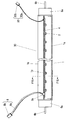
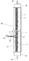
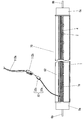
- FIG. 1 is a cross-sectional view of a tubular lamp according to a first embodiment cut along a tube axis.
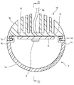
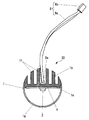
- FIG. 2 is a cross-sectional view of the tubular lamp of FIG. 1 cut along a plane orthogonal to the tube axis.
- FIG. 3 is a cross-sectional view showing a state in which the connector of the power feeding unit is fixed to the lamp body of the tubular lamp of FIG.
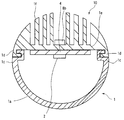
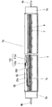
- FIG. 4 is a cross-sectional view of the tubular lamp according to the second embodiment cut along the tube axis.
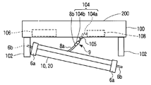
- FIG. 5 is a schematic view of a lighting fixture in which the tubular lamp of FIG. 1 or FIG. 4 is attached to the fixture body.
- FIG. 1 is a cross-sectional view of a tubular lamp according to a first embodiment cut along a tube axis.
- FIG. 2 is a cross-sectional view of the tubular lamp of FIG. 1 cut along a plane orthogonal to the tube axis.
- FIG. 3 is
- FIG. 6 is a schematic view showing a state in which the base of the tubular lamp is detached from one socket of the instrument body of FIG.
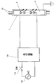
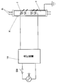
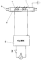
- FIG. 7 is a circuit diagram of the lighting fixture of FIG.
- FIG. 8 is an external perspective view showing a lighting apparatus according to the third embodiment.
- FIG. 9 is a side view of the lighting apparatus of FIG. 8 as viewed from the side.
- FIG. 10 is an exploded perspective view of the lighting fixture of FIG.
- FIG. 11 is a perspective view for explaining a connection state of the power feeding unit of the lighting fixture of FIG. 10.
- FIG. 12 is a plan view partially showing an enlarged main part of the reflector incorporated in the lighting apparatus of FIG. 13 is a partially enlarged perspective view showing an end portion of the tubular lamp of FIG. 10 on the power feeding side.
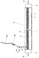
- FIG. 14 is a cross-sectional view of the tubular lamp of FIG. 10 cut along its tube axis.
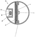
- FIG. 15 is a sectional view taken along line F15-F15 in FIG.
- FIG. 16 is a circuit diagram of the lighting fixture of FIG.
- FIG. 17 is a partially enlarged perspective view showing the structure of the main part of the lighting fixture according to the fourth embodiment.
- FIG. 18 is an external perspective view showing a lighting apparatus according to the fifth embodiment.
- FIG. 19 is a side view of the luminaire of FIG. 18 as viewed from the side.
- FIG. 20 is a partially enlarged perspective view showing a main part of the tubular lamp of the lighting apparatus of FIG.
- FIG. 21 is a cross-sectional view of the tubular lamp of FIG. 20 cut along the tube axis.
- FIG. 20 is a partially enlarged perspective view showing a main part of the tubular lamp of the lighting apparatus of FIG.
- FIG. 21 is a cross-sectional view of the tubular lamp of FIG.
- FIG. 22 is a cross-sectional view showing a state in which the feeder line of the tubular lamp of FIG. 21 is housed in the housing portion.
- 23 is a cross-sectional view taken along line F23-F23 in FIG.
- FIG. 24 is a cross-sectional view showing a modification of the tubular lamp of FIG.
- FIG. 25 is a circuit diagram of the lighting fixture of FIG.
- FIG. 26 is a cross-sectional view of the tubular lamp according to the sixth embodiment cut along the tube axis.
- FIG. 1 is a cross-sectional view of the tubular lamp 10 according to the first embodiment cut in the longitudinal direction along the tube axis.
- FIG. 2 shows a sectional view of the tubular lamp 10 cut along a plane orthogonal to the tube axis.
- a substantially cylindrical straight tube lamp extending straight as shown in FIG. 1 will be described as an example of a tubular lamp.
- the tubular lamp 10 has a structure that can be replaced in place of an existing straight tube fluorescent lamp (not shown). That is, the tubular lamp 10 of this embodiment can be attached to the fixture body 100 (described in detail later) of a lighting fixture that is used with a conventional straight tube fluorescent lamp.
- the tubular lamp 10 of the present embodiment includes a substantially cylindrical elongated straight tube lamp body 1, and a plurality (eight in this embodiment) of LEDs 2 (light emitting elements) arranged in the lamp body 1 in the longitudinal direction. ), Two substrates 4 on which the plurality of LEDs 2 are mounted, two bases 6 (attachment portions) attached to both ends in the longitudinal direction of the lamp body 1 for attaching the lamp body 1 to the fixture body 100, and 8 A power supply unit 8 for supplying power to the individual LEDs 2 is provided.
- the tubular lamp 10 of the present embodiment is characterized by a structure in which a plurality of LEDs 2 are arranged in parallel along the tube axis direction, and eight LEDs 2 are mounted side by side on each of the two substrates 4. ing.
- the power feeding unit 8 is provided on the back side of the lamp body 1 where the tubular lamp 10 faces the instrument body 100.
- the lamp body 1 has a light-transmitting cover 1a and a heat radiating portion 1b formed of an aluminum extruded material.
- the cover 1a has a shape obtained by cutting a cylinder substantially along its central axis, and has engaging edges 1c extending in the longitudinal direction for engaging with the heat radiating portion 1b at both side edges facing the heat radiating portion 1b.
- a material capable of diffusing light it is desirable to use a material capable of diffusing light.
- the heat dissipating part 1b has an engaging step part 1d extending in the longitudinal direction into which the engaging edge part 1c of the cover 1a is fitted.
- the heat dissipating part 1b is formed by integrating a mounting base 1e for mounting the substrate 4 on which the LED 2 is mounted and a plurality of heat dissipating fins 1f erected from the back side (upper side in FIG. 2) of the mounting base 1e. Have. It is desirable to use a metal material having high thermal conductivity as the material of the heat radiating part 1b.
- a connector 3a for connecting the feeder 8a is provided.
- the mounting base 1e in the gap between the two substrates 4 is formed with a lead-out hole 1g that penetrates the feeder 8a connected to the connector 3a from the back side of the lamp body 1 to the outside. Yes.
- the power supply line 8a led out through the lead-out hole 1g is drawn out from between the radiation fins 1f to the back side of the lamp body 1.
- the two caps 6 respectively support both ends of the lamp body 1 with respect to the fixture body 100 of a lighting fixture to which an existing straight tube type fluorescent lamp (not shown) can be attached. It is provided to dampen.
- the lamp body 1 is attached to the fixture body 100 by attaching the two caps 6 at both ends thereof to the two sockets 102 of the fixture body 100, respectively.
- the two caps 6 are strong enough to support the weight of the lamp body 1 by itself.
- the two caps 6 of the present embodiment each have a bottomed cylindrical cap 6a (fixing tool) attached to the end of the lamp body 1, and two pins 6b protruding from the bottom of the cap 6a. (Connector).
- the two pins 6 b are connected to the terminals of the socket 102 of the instrument body 100.
- the terminal shape of the base 6 is determined according to the terminal shape of the socket 102 on the instrument body 100 side.
- the cap 6a and the two pins 6b are each formed of metal. That is, each of the two caps 6 has conductivity. These two caps 6 are respectively attached to both ends of the lamp body 1 by adhering a cap 6a to the end of the lamp body 1 with an adhesive such as caulking or resin.
- the base 6 of the present embodiment is not provided as a power supply terminal for supplying power to the lamp body 1 from the side of the instrument body 100, but is simply provided for attaching the lamp body 1 to the instrument body 100. ing.
- the base 6 is connected to the socket 102 of the instrument body 100 in an insulated state.
- the two pins 6b of the base 6 are connected to the cap 6a in an insulated state.
- the two pins 6b of each base 6 are insulated from each other.
- the base 6 is electrically open, and even if power is supplied from the instrument body 100 side to the two pins 6b through the socket 102, the LED 2 in the lamp body 1 is energized through the base 6. It will never be done.
- a power supply unit 8 for supplying power to the plurality of LEDs 2 separately from the two caps 6.
- the power feeding unit 8 is provided in the lamp body 1 in order to connect the lamp body 1 to an external power source and supply power to the plurality of LEDs 2.
- the power supply unit 8 includes a power supply line 8a connected to the connector 3a mounted on the substrate 4, and a connector 8b provided at the tip of the power supply line 8a.
- the feed line 8a is led out from the back side of the lamp body 1 through the lead hole 1g of the heat radiating portion 1b, and is fixed to the lamp body 1 by a tension stopper or the like not shown here.
- a tension stopper or the like it is possible to prevent the stress applied to the power supply line 8a from being applied to the connection portion between the board 4 and the connector 3a. For example, even if the power supply line 8a is pulled, it is possible to prevent an undesired force from being applied to the connector 3a.
- the power supply line 8a may be accommodated in the lamp body 1 and the connector 8b may be directly attached to the lamp body 1 and fixed.
- the connector 8b of the power feeding unit 8 is fixed to the back surface of the mounting base 1e between the heat radiation fins 1f.
- the power supply unit 8 (power supply line 8 a and connector 8 b) is provided on the back side where the lamp main body 1 faces the appliance main body 100. For this reason, in a state where the lamp body 1 is attached to the fixture body 100, the feed line 8a and the connector 8b are hidden behind the lamp body 1, and the feed line 8a and the connector 8b from the front side of the lighting fixture, that is, the illumination light extraction side, are hidden. The connector 8b is difficult to see.
- the connecting part 104 on the side of the instrument main body 100 for connecting the power feeding part 8 of the lamp body 1 to the instrument main body 100 includes a connector 104 b connected to the connector 8 b of the power feeding part 8. And a connecting line 104a having the connector 104b at one end.
- the feed line 8a and the connection line 104a connected via the connectors 8b and 104b function as a feed line 9 for supplying power to the plurality of LEDs 2.
- a space for disposing the LED 2 inside the lamp body 1 is formed by the transparent cover 1a and the heat radiating portion 1b. That is, the outer shape of the lamp body 1 is substantially cylindrical, and the cover 1 a imparts translucency to at least a part of the lamp body 1.
- the LED 2 arranged in the lamp body 1 faces the inner surface of the cover 1a. For this reason, when the LED 2 is turned on, the light emitted from the LED 1 is emitted from the front of the tubular lamp 10 through the cover 1a.
- tubular lamp 10 of the present embodiment power is supplied from the outside via the power supply unit 8, and the LED 2 is turned on.
- the caps 6 at both ends of the lamp body 1 are provided only for supporting the lamp body 1 on the socket 102 of the instrument body 100.
- a tubular lamp 10 that can supply desired power to the lamp body 1 via the power feeding unit 8 and can improve versatility regardless of the lighting method of the existing lighting fixture. Can provide.
- the socket 102 of the fixture body 100 of the existing lighting fixture has deteriorated over time, it is possible to supply power through the power supply unit 8 provided separately from the base 6. Electrical connection reliability can be ensured.
- the socket 102 has deteriorated over time, there is a risk that the tubular lamp 10 may fall off.
- the lamp body 1 and the instrument body 100 are connected via the feeder 9. Therefore, even if the base 6 is detached from the socket 102, there is no fear that the lamp body 1 will fall.
- the power feeding portion 8 since the power feeding portion 8 is led out from the vicinity of the center of the lamp body 1 in the tube axis direction, the base 6 of the tubular lamp 10 is attached to the socket 102 of the instrument body 100. At this time, the power supply line 8a and the connector 8b of the power supply unit 8 are unlikely to interfere with the base 6 and the socket 102, and the workability of mounting the lamp main body 1 is easy even though the power supply line 8a is led out from the lamp main body 1. Can be.
- FIG. 4 shows a cross-sectional view of a tubular lamp 20 according to the second embodiment.
- the tubular lamp 20 has substantially the same structure as that of the first embodiment described above except that the lighting circuit 12 is mounted on the lamp body 1. Therefore, here, the same reference numerals are given to components that function in the same manner as the first embodiment described above, and detailed description thereof is omitted.
- a lighting circuit 12 is mounted on the back side of the substrate 4, and a power supply line 8 a of the power supply unit 8 is drawn from the lighting circuit 12. And the connector 8b of the electric power feeding part 8 is connected with the commercial power source which is not illustrated here. That is, commercial power is supplied to the lighting circuit 12.
- the lighting circuit 12 generates lighting power for lighting the LED 2 from the supplied commercial power source, and supplies it to the LED 2.
- the lighting circuit 12 is disposed in the lead-out hole 1g of the mounting base 1e, and the power supply line 8a of the power supply unit 8 is led out to the outside because it is centered in the tube axis direction of the lamp body 1.
- the shape and size of the lead-out hole 1g are set according to the size of the lighting circuit 12.
- the power supplied to the power supply unit 8 is not particularly limited.
- the connector unit 8b of the power supply unit 8 is tubular by connecting to the commercial power supply. It is preferable that the lamp 20 side and the commercial power source side be configured to be grounded.
- the tubular lamp 20 of the present embodiment is already installed for the luminaire using the straight-tube fluorescent lamp that has already been installed.
- the burden at the time of replacement is reduced.
- the lighting circuit 12 disposed in the tubular lamp 20 may be a part of a lighting circuit for controlling the lighting of the LED 2. That is, since the tubular lamp 20 is supported by the socket 102 configured to hold a conventional fluorescent lamp, it is preferable that the weight is as light as possible.
- the tubular lamp 20 can be reduced in weight and the burden at the time of replacement can be reduced. Is done.
- a circuit for converting a commercial power source into a DC power source may be disposed on the fixture body 100 side, and a circuit for supplying power from the DC power source to the LED 2 may be disposed in the lamp body 1.
- the substrate 4 is constituted by a single piece, the lighting circuit 12 is mounted on the back side of the substrate 4, and the lighting circuit 12 is disposed in the outlet hole 1g. is doing.
- the present embodiment is not limited to this configuration.
- a housing portion for disposing the lighting circuit 12 may be provided on the mounting base 1e, and the LED 2 is disposed in the lighting circuit 12. It may be arranged on the mounting surface side of the substrate 4 or may be configured separately from the substrate 4.
- FIG. 5 shows a schematic view of a lighting fixture 200 in which any one of the tubular lamps 10 and 20 of the first and second embodiments described above is attached to the fixture body 100.
- FIG. 6 is a schematic view showing a state in which the base 6 on one side (right side in the drawing) of the tubular lamps 10 and 20 is detached from the socket 102 from the state of FIG.
- the fixture body 100 of the lighting fixture 200 has two sockets 102 provided at both longitudinal ends thereof. Each socket 102 is suspended from the lower surface side at both longitudinal ends of the instrument body 100.
- the tubular lamps 10 and 20 are disposed between the two sockets 102 and are attached to the instrument body 100 by connecting the caps 6 at both ends to the terminals of the socket 102.
- the appliance body 100 also has a lighting device 106 that can supply power to a terminal (not shown) of the socket 102.
- the lighting device 106 is for controlling lighting of an existing straight tube fluorescent lamp. That is, since this lighting device 106 is an unnecessary configuration when the tubular lamps 10 and 20 of the above-described embodiments are used, the lighting device 106 may be removed at the same time as the replacement of the tubular lamps 10 and 20, but as it is You may leave in 100.
- the appliance main body 100 includes a lighting device 108 for controlling lighting of the plurality of LEDs 2 of the tubular lamps 10 and 20.
- the lighting device 108 is connected to the base end portion of the connection line 104a of the connection portion 104 described above.
- the connector 104b of the connection unit 104 is connected to the connector 8b of the power supply unit 8 on the lamp body 1 side. Then, the power from the lighting device 108 is supplied to the power supply unit 8 through the connection unit 104.
- connection wire 104 a led out from the instrument main body 100 is fixed to the instrument main body 100 by a tension stopper 105 in the middle thereof.
- a tension stopper 105 in the middle thereof.
- the circuit diagram of the lighting fixture 200 mentioned above is shown.
- the lighting device 108 is connected to the plurality of LEDs 2 via the feeder line 9.
- the power supply line 9 includes the power supply line 8a and the connector 8b of the power supply unit 8 on the lamp main body 1 side, and the connection line 104a and the connector 104b of the connection unit 104 on the fixture main body 100 side.
- a commercial AC power supply 110 is connected to the lighting device 108, and the plurality of LEDs 2 can be turned on and off by turning on and off the switch 112.
- the power supply is not connected to the nozzle
- the straight tube fluorescent lamp is removed from the fixture body 100 of the lighting fixture 200 installed on the ceiling surface of the building. Then, the lighting device 108 is attached in the appliance main body 100. A commercial power source is connected to the lighting device 108. At this time, an unnecessary lighting device 106 for a fluorescent lamp may be detached from the instrument main body 100. At this time, an insertion hole for leading the connection line 104a is formed in a part of the instrument body 100. Then, the connecting wire 104a is led out of the instrument body 100 through the insertion hole. Further, a midway portion of the connection line 104 a is fixed to the instrument main body 100 by a tension stopper 105.
- the caps 6 at both ends of the tubular lamp 10 or 20 are attached to the respective sockets 102.
- the connector 8b at the front end of the power supply line 8a drawn from the tubular lamps 10 and 20 and the connector 104b at the front end of the power supply line 104a are connected.
- the tubular lamps 10 and 20 are attached to the appliance main body 100, the power supply portion 8 on the lamp main body 1 side and the connection portion 104 on the appliance main body 100 side are connected to each other, so The trouble that the main body 1 falls can be prevented. That is, in this case, the lamp main body 1 is supported by being suspended from the fixture main body 100 via the feeder 9. In this case, each component 8 a, 8 b, 104 a, 104 b of the feeder 9 does not interfere with the socket 102 or the base 6, so that it does not interfere with the attachment of the base 6 to the socket 102.
- a plurality of lighting powers are supplied via the connection unit 104 and the power supply unit 8.
- a plurality of LEDs 2 emit light.
- the power supply unit 8 and the connection unit 104 may be automatically connected.
- a method is conceivable in which the power supply portion 8 and the connection portion of the connection portion 104 are fixed to the lamp main body 1 and the fixture main body 100, respectively, and when the base 6 is attached to the socket 102, the two are connected.
- the power feeding unit 8 and the connection unit 104 can be connected to each other by the operation of attaching the base 6 to the socket 102.
- connection structure By adopting the above connection structure, the lead wires and connectors of the power supply unit 8 and the connection unit 104 do not interfere with the socket 102 and the base 6, and the connection work between the power supply unit 8 and the connection unit 104 is facilitated. be able to.
- the positions for fixing the power feeding unit 8 and the connecting unit 104 are set on one end side of the lamp body 1 and one socket 102 side of the fixture body 100, respectively, and on the other end side, the tubular lamp 10 is set.
- 20 may be provided on the lamp body 1 and the fixture body 100, respectively.
- the attachment structure may be the same as that of the connector connection between the power feeding unit 8 and the connection unit 104, but does not supply power, and simply supports the other side of the tubular lamps 10 and 20 to the instrument body 100. Anything can be used.
- the tubular lamps 10 and 20 are supported by the instrument main body 100 by the connector connection between the power feeding unit 8 and the connection unit 104 and the engagement by the mounting structure at both ends of the tubular lamps 10 and 20, respectively. Even if the socket 102 is deteriorated and the base 6 cannot obtain a sufficient support force from the socket 102, the tubular lamps 10 and 20 can be attached to the instrument main body 100.
- FIG. 6 is a view showing a state when the support 6 of one (right side in the drawing) of the tubular lamps 10 and 20 is removed. As shown in FIG. 6, even when at least one of the caps 6 is detached, the tubular lamp 10, due to the connection between the power supply unit 8 and the connection unit 104 and the engagement between the other cap 6 and the socket 102, 20 can be held.
- the feeder 9 supports near the center of the lamp body 1, and the other base 6 of the lamp body 1 is supported by the socket 102. For this reason, the tubular lamps 10 and 20 do not fall even if one of the caps 6 is removed, and the user can be informed that the socket 102 has deteriorated.
- the power feeding portion 8 is led out from the vicinity of the central portion along the tube axis direction of the lamp body 1, as shown in FIG. 6, the load applied to the engaging portion between the power feeding portion 8 and the connecting portion 104. Therefore, the tubular lamps 10 and 20 can be held with a smaller engagement force.
- the instrument body 100 When replacing the tubular lamps 10 and 20 with existing straight tube fluorescent lamps, it is assumed that the instrument body 100 has already been used to some extent. When used for a long period of time, the socket 102 may deteriorate due to the influence of heat, ultraviolet rays or the like, or the cap 6 of the tubular lamps 10 and 20 may fall off the socket 102 for some reason such as vibration.
- the tubular lamps 10, 20 are engaged by the engagement between the power feeding portion 8 and the connection portion 104 and the engagement between the other cap 6 and the socket 102. It is comprised so that it can hold
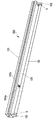
- FIG. 8 shows an external perspective view of the lighting fixture 300 of the present embodiment
- FIG. 9 shows a side view of the lighting fixture 300 viewed from the side
- FIG. 10 is an exploded perspective view of the lighting fixture 300.
- the lighting fixture 300 of the present embodiment also has a fixture main body 100 attached to a ceiling surface of a building and the like, and a tubular lamp 30 attached to the fixture main body 100.
- the instrument main body 100 has an existing straight tube fluorescent lamp attached thereto, and has a structure in which the tubular lamp 30 can be replaced in place of the straight tube fluorescent lamp. That is, the instrument body 100 attaches the tubular lamp 30 between the two sockets 102 by attaching the two bases 6 at both ends of the tubular lamp 30 to the two sockets 102 attached at both ends in the longitudinal direction.
- the tubular lamp 30 of the present embodiment has the same dimensions and outer shape as an existing straight tube fluorescent lamp. Specifically, it has the same size and shape as a 40 W straight tube fluorescent lamp.
- the tubular lamp 30 has a substrate 4 on which a plurality of LEDs 2 are mounted in a slender and substantially cylindrical lamp body 1, and has two caps 6 at both ends of the lamp body 1.
- the main body 1 includes a power feeding unit 8 and a grounding unit 32.
- the lamp body 1 has a substantially semi-cylindrical light-transmitting cover 1a and a substantially semi-cylindrical heat radiating portion 1b.
- the heat dissipating part 1b is made by extrusion molding from an aluminum material, and is formed by standing a plurality of heat dissipating fins 1f in the longitudinal direction from the back side of the mounting base 1e to which the substrate 4 on which the LED 2 is mounted is attached.
- the cover 1a is attached so that the opening side is fitted to the mounting base 1e of the heat radiating portion 1b, and forms a substantially cylindrical outer shape in cooperation with the heat radiating portion 1b.
- substrate 4 which mounted several LED2 is affixed on the front side of the attachment base 1e of the thermal radiation part 1b.
- the substrate 4 is formed in a substantially rectangular shape. Specifically, the four substrates 4 are arranged in the longitudinal direction and attached to the attachment base 1e of the heat radiating portion 1b so that the back side thereof is in close contact. Yes.
- the substrate 4 is made of a flat plate of glass epoxy resin that is an insulating material, and a wiring pattern made of copper foil is applied to the surface side. Further, a resist layer is appropriately applied.
- the material of the substrate 4 can be a ceramic material or a synthetic resin material when an insulating material is used. Furthermore, when it is made of metal, it is preferable to apply a material having good thermal conductivity such as aluminum and excellent heat dissipation.
- the light emitting element of this embodiment is LED2, which is a surface mount type LED package. Schematically, it is composed of an LED chip disposed in a main body made of ceramics, and a translucent resin for molding such as an epoxy resin or a silicone resin that seals the LED chip.
- the LED chip is a blue LED chip that emits blue light.
- a phosphor is mixed, and in order to be able to emit white light, a yellow phosphor that emits yellow light that is complementary to blue light is used. Yes.
- the LED 2 may be mounted directly on the substrate 4 or may be mounted with a bullet-type LED 2, and the mounting method and type are not particularly limited. In the present embodiment, four LEDs 2 are mounted linearly along the longitudinal direction on each substrate 4.
- the base 6 is, for example, a G13 type base, is configured to be attachable to the socket 102 of the lighting fixture 300 to which an existing straight tube fluorescent lamp is attached, and is fixed to both ends of the lamp body 1.
- the base 6 has a pair of pins 6b integrally protruding from the bottom of the cap 6a.
- the base 6 is made of metal, but the pair of pins 6b are electrically insulated from each other. Further, the pin 6b is not electrically connected to the LED 2.
- the base 6 is electrically open, and no current flows through the pin 6b even if power is supplied to the pin 6b. Therefore, as will be described later, when the base 6 is connected to the socket 102 of the fixture main body 100 of the lighting fixture 300, the base 6 simply serves to support the tubular lamp 30 on the fixture main body 100 without electrical conduction. It will be.
- the pin 6b may be an insulating material or a surface coated with an insulating material. In this case, in combination with the pair of pins 6b being electrically insulated, safety can be ensured twice.
- the power feeding unit 8 is connected to the power source side, that is, the instrument body 100 side, and has a function of supplying power to the LED 2 through the substrate 4.
- the power supply unit 8 includes a connector 8b and a power supply line 8a having the connector 8b at one end, and is offset toward one end in the longitudinal direction of the lamp body 1 (for example, the left end in FIG. 14). Arranged.
- the connector 8b is provided at the distal end of the power supply line 8a, is formed of a synthetic resin material, and is electrically connected to the connector 104b provided at the distal end of a connection line 104a described later that is led out from the instrument body 100 side. And mechanically connected.
- a connector 3 a that is electrically connected to the wiring pattern on the substrate 4 and electrically connected to the LED 2 is provided near one end (the left end in the drawing) of the substrate 4. Yes.
- the connector 3a protrudes upward from above the mounting base 1e through a through hole formed in the mounting base 1e of the heat radiating portion 1b.
- a base end portion of the power supply line 8a of the power supply unit 8 is firmly connected to the connector 3a.
- a part of the power supply line 8a may be fixed to the lamp body 1 by a tension stopper (not shown). Thereby, it can be avoided that the stress applied to the power supply line 8a is applied directly to the connecting portion between the power supply line 8a and the connector 3a.
- the connector 8b of the power supply unit 8 may be directly fixed to the back side of the substrate 4 without providing the power supply line 8a. In this case, the power feeding unit 8 is configured by the connector 8b.
- the grounding portion 32 is provided for grounding the metal heat radiating portion 1b of the lamp body 1 to the ground terminal of the terminal block 110 provided in the fixture body 100.
- the grounding portion 32 is provided so as to be offset toward the other end (right end in FIG. 14) side of the lamp body 1.
- the grounding portion 32 on the lamp body 1 side includes a grounding wire 32a and a connector 32b attached to the tip of the grounding wire 32a.
- the base end portion of the ground wire 32a is fixed to the mounting base 1e of the heat radiating portion 1b by a fixing means such as a screw. Further, the ground wire 32a may also be fixed to the lamp body 1 by a tension stopper or the like (not shown).
- the connector 32b is provided at the tip of the ground wire 32a, is formed of a synthetic resin material, and is connected to the connector 112b provided at the tip of the ground wire 112a led out from the instrument body 100 side described later. .
- the lamp body 1 side ground wire 32a, the connector 32b, the fixture body 100 side ground wire 112a, and the connector 112b function as a ground wire as a whole, and the lamp body 1 is electrically connected to the fixture body 100. It is designed to be connected mechanically.
- the instrument body 100 is formed in a box shape having an open portion whose bottom surface is open, and is accommodated in the instrument body 100 with sockets 102 attached to both ends.
- the lighting device 108, the terminal block 110, and the reflection plate 120 are provided.
- the socket 102 includes a power supply terminal for connecting the two pins 6b of the base 6 at both ends of the tubular lamp 30.
- the power supply terminal of the socket 102 is not electrically connected to the base 6 of the tubular lamp 30 and is electrically opened.
- the lighting device 108 is connected to a commercial AC power source AC, and receives the AC power source AC to generate a DC output.
- the lighting device 108 is configured, for example, by connecting a smoothing capacitor between output terminals of a full-wave rectifier circuit, and connecting a DC voltage conversion circuit and current detection means to the smoothing capacitor.
- connection line 104a is led out from the lighting device 108, and a connector 104b is provided at the tip of the connection line 104a.
- the connector 104b is electrically and mechanically connected to the connector 8b of the power feeding unit 8 on the lamp body 1 side.
- the terminal block 110 is connected to a power supply line and a ground line (not shown) from outside the instrument body 100. Further, the lighting device 108 is connected to the terminal block 110 by a lead wire. Furthermore, the grounding portion 32 on the lamp body 1 side is electrically connected to the terminal block 110 via the grounding wire 112a and the connector 112b.
- the connector 112b is connected to the connector 32b of the grounding portion 32, and the base end portion of the grounding wire 112a with the connector 112b attached to the distal end is connected to the instrument body 100 by screwing or the like. Since the fixture main body 100 is electrically connected to the ground terminal of the terminal block 110, the lamp main body 1 is thereby grounded.
- the reflector 120 is attached so as to cover the open part on the lower surface side of the instrument body 100.
- rectangular cutout portions 120a into which the sockets 102 are fitted are formed.
- U-shaped insertion portions 120b and 120c that are continuous with the notch portion 120a are formed at the edge portions on the side where these notch portions 120a face the socket 102, respectively.
- this embodiment presupposes what is called renewal which replaces the tubular lamp 30 instead of the straight tube
- a straight tube fluorescent lamp (not shown) is removed from the existing instrument body 100, and the reflector 120 is removed.
- a lighting device (not shown) for controlling the lighting of the existing straight tube fluorescent lamp is removed, and a lighting device 108 for controlling the lighting of the tubular lamp 30 is newly installed in the instrument main body 100.
- the lead wire drawn out from the lighting device 108 is connected to the terminal block 110.
- the U-shaped insertion part 120b, 120c is formed in the longitudinal direction both ends of the reflecting plate 120 using a tool etc.
- the connecting wire 104a connected to the lighting device 108 is inserted and disposed so as to be led out from one insertion portion 120b of the reflector 120, and is electrically connected to the fixture body 100 and attached.
- the grounding wire 112a is inserted and disposed so as to be led out from the other insertion portion 120c of the reflector 120, and the reflector 120 is attached to the instrument body 100.
- the connector 8b of the power supply unit 8 on the lamp body 1 side is connected to the connector 104b provided on the connection line 104a on the apparatus body 100 side, and the connector 112b attached to the tip of the grounding wire 112a on the apparatus body 100 side is connected.
- the connector 32b of the grounding part 32 on the lamp body 1 side is connected.
- the caps 6 at both ends of the tubular lamp 30 are mounted on the socket 102. This completes the attachment of the tubular lamp 30 to the instrument body 100. As a result, electric power is supplied to the tubular lamp 30 from the power supply unit 8, and the tubular lamp 30 is supported by the socket 102 and is kept attached. Depending on the deterioration state of the socket 102, the socket 102 may be replaced simultaneously with the replacement of the tubular lamp 30.
- the lighting device 108 is connected to a commercial AC power supply AC, and an output from the lighting device 108 is supplied to the LED 2.
- the two pins 6 b protruding from both ends of the lamp body 1 are not electrically connected, and the lamp body 1 is not supplied with power through the base 6. it is obvious.
- the plurality of LEDs 2 are energized via the connection line 104 a, the connector 104 b, the connector 8 b, the power supply line 8 a, and the substrate 4.
- Each LED 2 lights up.
- the light emitted from the LED 2 passes through the cover 1a and is emitted downward to illuminate a predetermined range.
- connection line 104 a that connects the power supply side, that is, the power supply unit 8 of the lamp main body 100 and the lamp body 1, is inserted through the notch 120 a of the reflector 120 for fitting the socket 102. Derived from the unit 120b. That is, the connection line 104 a led out from the instrument body 100 is wired along the one socket 102.
- connection line 104a, the connector 104b, the connector 8b, and the power supply line 8a constituting the power supply line 9 are not concealed inside the socket 102, and the appearance is improved.
- connection line 104a, the connector 104b, the connector 8b, and the power supply line 8a are arranged on the back side of the tubular lamp 30, they do not become an obstacle to light emitted from the LED 2.
- the connectors 104a and 8b formed of the synthetic resin material are hidden behind the tubular lamp 30, the dose of ultraviolet rays irradiated by the long-term use of the tubular lamp 30 can be reduced. Deterioration can be suppressed.
- the effect by the insertion part 120b mentioned above becomes the same also about the insertion part 120c by the side of a grounding part.
- the tubular lamp 30 when the tubular lamp 30 is replaced with an existing straight tube fluorescent lamp, it is assumed that the instrument body 100 has already been used for some time. That is, when the instrument main body 100 to which the tubular lamp 30 is attached has been used for a long time, there is a high possibility that the socket 102 has deteriorated due to the influence of heat, ultraviolet rays or the like. For this reason, when the tubular lamp 30 is attached to the socket 102 of the instrument main body 100 thus deteriorated, the base 6 of the tubular lamp 30 may come off from the socket 102 due to vibration or the like, and the tubular lamp 30 may fall. .
- the power supply unit 8 is connected to the other end of the tubular lamp 30, both end sides thereof are supported in cooperation with the power feeding portion 8, and further safety can be ensured.
- the power supply line 8a of the power supply unit 8 and the ground line 32a of the grounding unit 32 are adjusted to have substantially the same length.
- the power feeding unit 8 is disposed near the end of the lamp body 1 of the tubular lamp 30, it does not stand out in appearance, and can further shorten the power feeding line 8a.
- the grounding portion 32 is connected to the heat radiating portion 11b of the lamp body 1, the insulating property of the substrate 4 on which the LED 2 is mounted is temporarily deteriorated, and the insulating property between the substrate 4 and the heat radiating portion 1b is lowered. Even if the current leaks to the heat radiating portion 1b, the heat radiating portion 1b is grounded, so that it is possible to prevent a risk of electric shock during maintenance such as cleaning or replacement of the tubular lamp 30.
- FIG. 17 shows a partially enlarged perspective view of the main part of the luminaire according to the fourth embodiment.
- symbol is attached
- This embodiment is characterized in that an insertion portion 120b for inserting a connection line 104a led out from the instrument body 100 side is formed in the socket 102 instead of being provided in the reflection plate 120.
- the insertion portion 120 b is configured by a recess formed inside the socket 102. This recess is engraved in a substantially semi-cylindrical shape so that the connection line 104a connected to the lighting device 108 passes, and specifically, between the rectangular notch 120a formed in the reflector 120. Thus, the insertion part 120b is formed.
- the existing socket can be replaced with the socket 102 in which the insertion portion 120b is formed, or the insertion portion 120b can be processed into the existing socket.
- an insertion portion 120 c through which the ground wire 112 a led out from the instrument main body 100 is inserted is similarly formed inside the socket 102.
- the same operational effects as those of the third embodiment described above can be achieved. That is, also in the present embodiment, the power supply line and the ground line can be wired along the socket 102, and the lead wires and connectors are not visible from the front side of the lighting fixture, and the appearance can be improved.
- FIG. 18 shows an external perspective view of the lighting fixture 500 of this embodiment
- FIG. 19 shows a side view of the lighting fixture 500 viewed from the side.
- the lighting fixture 500 includes a fixture main body 100 installed on a ceiling surface of a building and the like, and a tubular lamp 50 attached to the fixture main body 100.
- the instrument main body 100 has an existing straight tube fluorescent lamp attached thereto, and has a structure in which the tubular lamp 50 can be replaced in place of the straight tube fluorescent lamp. That is, the instrument body 100 attaches the tubular lamp 50 between the two sockets 102 by connecting the two bases 6 at both ends of the tubular lamp 50 to the two sockets 102 attached at both ends in the longitudinal direction.
- the tubular lamp 50 of the present embodiment has the same dimensions and outer shape as those of an existing straight tube fluorescent lamp. Specifically, it has the same size and shape as a 40 W straight tube fluorescent lamp.
- the tubular lamp 50 has a substrate 4 on which a plurality of LEDs 2 are mounted in a slender and substantially cylindrical lamp body 1, and has two caps 6 at both ends of the lamp body 1.
- the main body 1 includes a power feeding unit 8.
- the lamp body 1 is made by extrusion molding of a translucent synthetic resin material, has a substantially cylindrical outer shape, and has an internal space in which a plurality of LEDs 2 are arranged.
- a groove-like storage recess 52 having a substantially U-shaped cross section along the longitudinal direction is formed.
- the housing recess 52 functions as a housing portion that houses a power supply line and a ground wire that connect the lamp body 1 and the instrument body 100.
- the inner space of the lamp body 1 is provided with a rectangular plate-like heat radiation portion 1b that is elongated along the longitudinal direction.
- the heat radiating portion 1b is made of an aluminum material having good thermal conductivity.
- substrate 4 which mounted several LED2 is affixed on the front side of the thermal radiation part 1b.
- substrate 4 is formed in the substantially rectangular shape, and, specifically, the four board
- the substrate 4 is made of a flat plate of glass epoxy resin that is an insulating material, and a wiring pattern made of copper foil is applied to the surface side. Further, a resist layer is appropriately applied.
- the material of the substrate 4 can be a ceramic material or a synthetic resin material when an insulating material is used. Furthermore, when it is made of metal, it is preferable to apply a material having good thermal conductivity such as aluminum and excellent heat dissipation.
- the light emitting element of this embodiment is LED2, which is a surface mount type LED package. Schematically, it is composed of an LED chip disposed in a main body made of ceramics, and a translucent resin for molding such as an epoxy resin or a silicone resin that seals the LED chip.
- the LED chip is a blue LED chip that emits blue light.
- a phosphor is mixed, and in order to be able to emit white light, a yellow phosphor that emits yellow light that is complementary to blue light is used. Yes.
- the LED 2 may be mounted directly on the substrate 4 or may be mounted with a bullet-type LED 2, and the mounting method and type are not particularly limited. In the present embodiment, four LEDs 2 are mounted linearly along the longitudinal direction on each substrate 4.
- the base 6 is, for example, a G13 type base, is configured to be attachable to the socket 102 of the lighting fixture 500 to which an existing straight tube fluorescent lamp is attached, and is fixed to both ends of the lamp body 1.
- the base 6 has a pair of pins 6b integrally protruding from the bottom of the cap 6a.
- the base 6 is made of metal, but the pair of pins 6b are electrically insulated from each other. Further, the pin 6b is not electrically connected to the LED 2.
- the base 6 is electrically open, and no current flows through the pin 6b even if power is supplied to the pin 6b. Therefore, as will be described later, when the base 6 is connected to the socket 102 of the fixture main body 100 of the lighting fixture 500, the base 6 simply serves to support the tubular lamp 50 on the fixture main body 100 without being electrically conductive. It will be.
- the pin 6b may be an insulating material or a surface coated with an insulating material. In this case, in combination with the pair of pins 6b being electrically insulated, safety can be ensured twice.
- the power feeding unit 8 is connected to the power source side, that is, the instrument body 100 side, and has a function of supplying power to the LED 2 through the substrate 4.
- the power supply unit 8 includes a connector 8b and a power supply line 8a having the connector 8b at one end, and is offset toward one end in the longitudinal direction of the lamp body 1 (for example, the left end in FIG. 20). Arranged.
- the connector 8b is provided at the distal end of the power supply line 8a, is formed of a synthetic resin material, and is electrically connected to the connector 104b provided at the distal end of a connection line 104a described later that is led out from the instrument body 100 side. And mechanically connected.
- a connector 3 a electrically connected to the wiring pattern on the substrate 4 and electrically connected to the LED 2 is provided near one end (the left end in the drawing) of the back surface side of the substrate 4. Yes.
- the connector 3a protrudes to the back side of the heat radiating portion 1b through a through hole formed in the heat radiating portion 1b.
- a base end portion of the power supply line 8a of the power supply unit 8 is firmly connected to the connector 3a.
- the power supply line 8 a led out from the connector 3 a to the back side is led out to the back side of the lamp body 1 through a through hole formed in the bottom of the housing recess 52.
- a part of the power supply line 8a may be fixed to the lamp body 1 by a tension stopper (not shown). Thereby, it can be avoided that the stress applied to the power supply line 8a is applied directly to the connecting portion between the power supply line 8a and the connector 3a. Or you may make it fix the connector 8b of the electric power feeding part 8 to the accommodation recess 52 instead of providing a tension
- the connector 8b of the power supply unit 8 may be directly fixed to the back side of the substrate 4 without providing the power supply line 8a. In this case, the power feeding unit 8 is configured by the connector 8b.
- the instrument main body 100 is formed in a box shape having an open portion whose lower surface side is open, the socket 102 attached to both ends, the lighting device 108 and the terminal block 110 accommodated in the instrument main body 100, And a reflection plate 120 attached so as to cover the open part on the lower surface side.
- the socket 102 is provided with a power feeding terminal for connecting the two pins 6b of the base 6 at both ends of the tubular lamp 50.
- the power supply terminal of the socket 102 is not electrically connected to the base 6 of the tubular lamp 50 and is electrically opened.
- the lighting device 108 is connected to a commercial AC power source AC, and receives the AC power source AC to generate a DC output.
- the lighting device 108 is configured, for example, by connecting a smoothing capacitor between output terminals of a full-wave rectifier circuit, and connecting a DC voltage conversion circuit and current detection means to the smoothing capacitor.
- connection line 104a is led out from the lighting device 108, and a connector 104b is provided at the tip of the connection line 104a.
- the connector 104b is electrically and mechanically connected to the connector 8b of the power feeding unit 8 of the lamp body 1.
- the reflective plate 120 is formed with a penetrating circular insertion portion 120a (FIG. 18) through which the connection line 104a drawn from the lighting device 108 is inserted.
- the insertion portion 120a is provided with a bush as a wiring protection material. Further, the insertion portion 120a is provided with a tension stopper 130 (FIG. 19) for fixing the connecting wire 104a to the instrument main body 100.
- the connecting wire 104a and the connector 104b that have passed through the insertion part 120a, and the power feeding part 8 connected to the connector 104b are accommodated in an accommodation recess 52 provided on the back side of the lamp body 1. Therefore, it can suppress that these electric power feeding line and a connector protrude from the outer shell of the lamp main body 1, or can protrude, and a wiring process can be performed well.
- 22 and 23 show a state where the feeder 8a and the connector 8b are housed in the housing recess 52.
- the terminal block 110 is connected to a power supply line and a ground line (not shown) from outside the instrument body 100. Further, the lighting device 108 is connected to the terminal block 110 by a lead wire.
- this embodiment presupposes what is called renewal which replaces the tubular lamp 50 instead of the straight tube
- a straight tube fluorescent lamp (not shown) is removed from the existing instrument body 100, and the reflector 120 is removed.
- a lighting device (not shown) for controlling lighting of the existing straight tube fluorescent lamp is removed, and a lighting device 108 for newly controlling lighting of the tubular lamp 50 is attached to the instrument main body 100.
- the lead wire drawn out from the lighting device 108 is connected to the terminal block 110.
- the insertion portion 120a is formed in the reflector 120 using a tool or the like.
- the connecting wire 104 a connected to the lighting device 108 is passed through the insertion portion 120 a of the reflecting plate 120, and the reflecting plate 12 is attached to the instrument body 100.
- the connecting wire 104a and the connector 104b of the connecting portion 104 are led out to the front of the instrument body 100.
- the connector 8b of the power supply unit 8 on the lamp body 1 side is connected to the connector 104b provided at the tip of the connection line 104a drawn out from the fixture body 100, and the connection line 104a, the connector 104b, the power supply line 8a, Further, the continuous feeder 9 including the connector 8b is disposed so as to be housed in the housing recess 52 provided on the back side of the lamp body 1.
- the caps 6 at both ends of the tubular lamp 50 are respectively attached to the sockets 102. This completes the attachment of the tubular lamp 50 to the instrument body 100.
- the power supply line 9 can be housed in the housing recess 52 and can be prevented from being inadvertently protruding.
- the long power supply line 9 may be disposed along the storage recess 52, and the storage is facilitated.
- the tubular lamp 50 When the tubular lamp 50 is attached to the instrument main body 100 as described above, electric power is supplied to the tubular lamp 50 from the power supply unit 8, and the tubular lamp 50 is supported by the socket 102 and is attached. It will be retained. Depending on the deterioration state of the socket 102, the socket 102 may be replaced simultaneously with the replacement of the tubular lamp 50.
- the lighting device 108 is connected to a commercial AC power supply AC, and an output from the lighting device 108 is supplied to the LED 2.
- the two pins 6 b protruding from both ends of the lamp body 1 are not electrically connected, and the lamp body 1 is not supplied with power through the base 6. it is obvious.
- the plurality of LEDs 2 are energized via the connection line 104 a, the connector 104 b, the connector 8 b, the power supply line 8 a, and the substrate 4.
- Each LED 2 lights up. Light emitted from the LED 2 passes through the translucent lamp body 1 and is emitted downward to illuminate a predetermined range.
- the power supply line 9 connecting the connection line 104a, the connector 104b, the connector 8b, and the power supply line 8a is accommodated in the storage recess 52 provided on the back side of the lamp body 1, the power supply line 9 is connected to the lamp body 1. Protruding from the outer shell or protruding from the outer shell can be suppressed, and the wiring process can be performed well.
- the feeder 9 since the feeder 9 is housed in the housing recess 52 on the back side of the tubular lamp 50, the feeder 9 does not become an obstacle to the radiation of light from the LED 2 or the reflected light from the reflector 120. .
- the connectors 8b and 104b made of synthetic resin material are accommodated in the accommodation recess 52, the dose of ultraviolet rays irradiated to these connectors by the long-term use of the tubular lamp 50 is substantially eliminated. And deterioration of the connector due to ultraviolet rays can be suppressed.
- the tubular lamp 50 when the tubular lamp 50 is replaced with an existing straight tube fluorescent lamp, it is assumed that the instrument body 100 has already been used for some time. That is, when the instrument main body 100 to which the tubular lamp 50 is attached has been used for a long time, it is highly likely that the socket 102 has deteriorated due to the influence of heat, ultraviolet rays or the like. For this reason, when the tubular lamp 50 is attached to the socket 102 of the instrument body 100 thus deteriorated, the base 6 of the tubular lamp 50 may come off from the socket 102 due to vibration or the like, and the tubular lamp 50 may fall. .
- FIG. 24 shows a modification of the above-described fifth embodiment.
- the storage recess 52 includes pressing pieces 54 on both sides of the opening so that the feeder 9 is not removed from the opening on the back side.
- the pressing piece 54 at the edge of the opening of the storage recess 52, the storage of the feeder 9 into the storage recess 52 is ensured.
- the tubular lamp 60 of this embodiment is characterized by a structure in which the power supply line 8a of the power supply unit 8 and the ground line 32a of the grounding unit 32 are drawn together from the back side of the lamp body 1.
- the ground wire 32a is connected and fixed at its base end to the back side of the heat radiating portion 1b by screws or the like.
- the base end part of the feeder 8a is connected to the board
- the tip of the ground wire 32a is connected together to the connector 8b of the power feeding unit 8 together. That is, the power supply line 8a for supplying electric power and the ground line 32a for grounding the tubular lamp 60 are connected to the connector 8b, and these can be connected by one connector 8b. Therefore, it is possible to connect the power feeding unit 8 and the grounding unit 32 at once.
- the ground wire 32a is also housed in the housing recess 52 at the same time. It will be. Since the housing recess 52 is formed on the back side of the lamp body 1, it is possible to suppress the configuration of the power feeding unit 8 and the grounding unit 32 from protruding from or protruding from the outer shell of the lamp body 1. Wiring processing can be performed well.
- tubular lamp 70 according to a seventh embodiment will be described with reference to FIGS. Also here, the same reference numerals are given to components that function in the same manner as in the fifth embodiment described above, and detailed description thereof will be omitted.
- the tubular lamp 70 of the present embodiment is of a type that feeds power via the caps 6 at both ends of the lamp body 1, unlike the first to sixth embodiments described above. That is, the tubular lamp 70 is supplied with power through the terminal of the socket 102 in a state of being attached to the instrument main body 100 in the same manner as a conventional straight fluorescent lamp.
- the ground wire 32a of the grounding unit 32 is stored in the storage recess 52 in this embodiment.
- the storage recess 52 is provided on the back side of the lamp body 1.
- the grounding portion 32 on the lamp body 1 side includes a grounding wire 32a and a connector 32b.
- a base end portion of the ground wire 32a is fastened and fixed to the heat radiating portion 1b having conductivity in the lamp body 1 by screws or the like.
- the connector 32b of the grounding portion 32 on the lamp body 1 side is connected to the connector 112b provided at the tip of the grounding wire 112a drawn out from the fixture body 100.
- the ground terminal of the terminal block 110 electrically connected to the conductive heat radiating portion 1b is grounded via a ground wire (not shown). Therefore, the lamp body 1 is grounded via the ground wire 32a, the connector 32b, the ground wire 112a, the connector 112b, the heat radiating portion 1b, the terminal block 110, and the ground wire.
- the lead wire 32 is connected to the grounding portion 32 on the lamp body 1 side, the connector 32b, and derived from the fixture body 1 side.
- the grounding wire 112a and the connector 112b thus formed can be housed in the housing recess 52 provided on the back side of the lamp body 1. Thereby, it can suppress that the ground wire which connected the lamp
- a tubular lamp is not limited to a form compatible with a straight fluorescent lamp. It can also be configured in a form compatible with a single-end type fluorescent lamp. Further, the lighting device 108 that controls the lighting of the LED 2 may be disposed on the fixture body 100 side or the lamp body 1 side.
- Lamp body 1 ... Lamp body, 2 ... LED, 4 ... substrate 6 ... 8 ... Feeding part, 8a ... feeder line, 8b ... Connector, 10 ... Tube lamp, 100 ...
Landscapes
- Engineering & Computer Science (AREA)
- General Engineering & Computer Science (AREA)
- Microelectronics & Electronic Packaging (AREA)
- Physics & Mathematics (AREA)
- Optics & Photonics (AREA)
- Geometry (AREA)
- Non-Portable Lighting Devices Or Systems Thereof (AREA)
- Fastening Of Light Sources Or Lamp Holders (AREA)
- Arrangement Of Elements, Cooling, Sealing, Or The Like Of Lighting Devices (AREA)
Abstract
Description
図1には、第1の実施形態に係る管状ランプ10をその管軸に沿って長手方向に切断した断面図を示してある。また、図2には、この管状ランプ10をその管軸と直交する面で切断した断面図を示してある。以下に説明する各実施形態では、図1に示すような真っ直ぐに伸びた略円筒形の直管形のランプを管状ランプの一例として説明する。
この管状ランプ20は、ランプ本体1に点灯回路12を実装した以外、上述した第1の実施形態と略同じ構造を有する。よって、ここでは、上述した第1の実施形態と同等に機能する構成要素については同一符号を付してその詳細な説明を省略する。
点灯装置108は、給電線9を介して複数個のLED2に接続されている。ここで言う給電線9は、上述したように、ランプ本体1側の給電部8の給電線8aとコネクタ8b、および器具本体100側の接続部104の接続線104aとコネクタ104bを含むものである。
2…LED、
4…基板、
6…口金、
8…給電部、
8a…給電線、
8b…コネクタ、
10…管状ランプ、
100…器具本体、
102…ソケット、
120…反射板。
Claims (13)
- 透光性を有する細長い筒状のランプ本体と、
このランプ本体内に配置された複数の発光素子と、
上記ランプ本体の長手方向両端をそれぞれ器具本体のソケットに取り付けるための2つの取付部と、
これら2つの取付部とは別に上記ランプ本体に設けられた、上記発光素子に給電するための給電部と、
を有する管状ランプ。 - 上記取付部は、上記ソケットに対して絶縁状態で接続する請求項1の管状ランプ。
- 上記取付部は、上記ソケットの端子に接続する接続子と、この接続子を上記ランプ本体の長手方向両端部に固定する固定具と、を有し、上記接続子と上記固定具は絶縁状態で接続されている請求項1の管状ランプ。
- 上記取付部は、上記ソケットの端子に接続する2つの接続子を有し、これら2つの接続子は互いに絶縁状態にされている請求項1の管状ランプ。
- 上記給電部は、上記ランプ本体が上記器具本体に対向する背面側に設けられている請求項1の管状ランプ。
- 上記給電部は、上記2つの取付部の少なくとも一方が上記ソケットから外れた状態で、上記ランプ本体を上記器具本体に対して吊り下げ支持する給電線を有する請求項5の管状ランプ。
- 上記器具本体と上記給電部を接続した給電線を収容するための収容部を上記ランプ本体の上記背面側に有する請求項5の管状ランプ。
- 上記収容部は、上記ランプ本体を接地するための接地線をさらに収容する請求項7の管状ランプ。
- 上記ランプ本体を接地するための接地線を収容する収容部を当該ランプ本体の上記背面側に有する請求項5の管状ランプ。
- 上記給電部は、外部電源を接続するための、上記ランプ本体に固設されたコネクタを有する請求項5の管状ランプ。
- 上記2つのソケットの他に上記給電部を接続するための接続部を有する器具本体と、
上記2つのソケットに上記2つの取付部をそれぞれ取り付けて、上記接続部に上記給電部を接続した、請求項1乃至請求項10のいずれかの管状ランプと、
を有する照明器具。 - 上記器具本体の上記接続部と上記ランプ本体の上記給電部とをつなげた給電線を通すため上記ソケットに沿って上記器具本体に設けられた挿通部を有する請求項11の照明器具。
- 上記管状ランプと上記器具本体とをつなげた接地線を通すため上記ソケットに沿って上記器具本体に設けられた挿通部を有する請求項11の照明器具。
Priority Applications (4)
| Application Number | Priority Date | Filing Date | Title |
|---|---|---|---|
| CN201180014683.0A CN102803829B (zh) | 2010-03-30 | 2011-03-28 | 管状灯及照明器具 |
| JP2011533028A JPWO2011122518A1 (ja) | 2010-03-30 | 2011-03-28 | 管状ランプおよび照明器具 |
| US13/634,648 US8864511B2 (en) | 2010-03-30 | 2011-03-28 | Tube lamp and luminaire |
| EP11762742.2A EP2554895A4 (en) | 2010-03-30 | 2011-03-28 | TUBULAR LAMP AND LIGHTING EQUIPMENT |
Applications Claiming Priority (6)
| Application Number | Priority Date | Filing Date | Title |
|---|---|---|---|
| JP2010-077920 | 2010-03-30 | ||
| JP2010077920 | 2010-03-30 | ||
| JP2010102438 | 2010-04-27 | ||
| JP2010102439 | 2010-04-27 | ||
| JP2010-102438 | 2010-04-27 | ||
| JP2010-102439 | 2010-04-27 |
Publications (1)
| Publication Number | Publication Date |
|---|---|
| WO2011122518A1 true WO2011122518A1 (ja) | 2011-10-06 |
Family
ID=44712215
Family Applications (1)
| Application Number | Title | Priority Date | Filing Date |
|---|---|---|---|
| PCT/JP2011/057528 Ceased WO2011122518A1 (ja) | 2010-03-30 | 2011-03-28 | 管状ランプおよび照明器具 |
Country Status (5)
| Country | Link |
|---|---|
| US (1) | US8864511B2 (ja) |
| EP (1) | EP2554895A4 (ja) |
| JP (1) | JPWO2011122518A1 (ja) |
| CN (1) | CN102803829B (ja) |
| WO (1) | WO2011122518A1 (ja) |
Cited By (14)
| Publication number | Priority date | Publication date | Assignee | Title |
|---|---|---|---|---|
| JP2013084469A (ja) * | 2011-10-11 | 2013-05-09 | Rohm Co Ltd | 電源モジュール、led照明ユニット、led照明装置、および、led照明システム |
| JP2013089358A (ja) * | 2011-10-14 | 2013-05-13 | Panasonic Corp | 光源及びそれを用いた照明装置 |
| JP2013143237A (ja) * | 2012-01-10 | 2013-07-22 | Hitachi Appliances Inc | 照明装置 |
| BE1020374A3 (nl) * | 2012-01-19 | 2013-08-06 | Kips Led Verlichting Bv Met Beperkte Aansprakelijkheid | Led-buislamp. |
| EP2511589A3 (de) * | 2011-04-12 | 2013-08-14 | Heribert R. Albert | Beleuchtungseinrichtung, Leuchtkörperhalter und Leuchtkörper dafür |
| JP2013191536A (ja) * | 2012-03-14 | 2013-09-26 | Lextar Electronics Corp | 発光装置 |
| WO2014136160A1 (ja) * | 2013-03-04 | 2014-09-12 | パナソニック株式会社 | 光源ユニット及び照明器具 |
| JP2014170732A (ja) * | 2013-11-15 | 2014-09-18 | Panasonic Corp | 光源ユニット及び照明器具 |
| CN104214574A (zh) * | 2014-09-22 | 2014-12-17 | 苏州承源光电科技有限公司 | Led室内照明灯 |
| US9188324B2 (en) | 2012-04-13 | 2015-11-17 | Hella Kgaa Hueck & Co. | Modular LED light |
| JP2016046053A (ja) * | 2014-08-21 | 2016-04-04 | アイリスオーヤマ株式会社 | 照明装置用発光ユニット及び照明装置 |
| US10222005B2 (en) | 2015-07-24 | 2019-03-05 | Sidney Howard Norton | Method and assembly for replacing fluorescent lights |
| US11002438B2 (en) | 2019-04-03 | 2021-05-11 | Sidney Howard Norton | Adjustable clip-on base for LED assembly |
| JP2021108298A (ja) * | 2017-04-24 | 2021-07-29 | 株式会社ホタルクス | Led光源ユニット |
Families Citing this family (33)
| Publication number | Priority date | Publication date | Assignee | Title |
|---|---|---|---|---|
| US8118447B2 (en) | 2007-12-20 | 2012-02-21 | Altair Engineering, Inc. | LED lighting apparatus with swivel connection |
| US8360599B2 (en) | 2008-05-23 | 2013-01-29 | Ilumisys, Inc. | Electric shock resistant L.E.D. based light |
| US8901823B2 (en) | 2008-10-24 | 2014-12-02 | Ilumisys, Inc. | Light and light sensor |
| US8324817B2 (en) | 2008-10-24 | 2012-12-04 | Ilumisys, Inc. | Light and light sensor |
| US8653984B2 (en) | 2008-10-24 | 2014-02-18 | Ilumisys, Inc. | Integration of LED lighting control with emergency notification systems |
| US8214084B2 (en) | 2008-10-24 | 2012-07-03 | Ilumisys, Inc. | Integration of LED lighting with building controls |
| US7938562B2 (en) | 2008-10-24 | 2011-05-10 | Altair Engineering, Inc. | Lighting including integral communication apparatus |
| US8541958B2 (en) | 2010-03-26 | 2013-09-24 | Ilumisys, Inc. | LED light with thermoelectric generator |
| WO2011119958A1 (en) | 2010-03-26 | 2011-09-29 | Altair Engineering, Inc. | Inside-out led bulb |
| TW201144662A (en) * | 2010-04-27 | 2011-12-16 | Toshiba Lighting & Amp Technology Corp | Luminous element lamp of fluorescent lamp shape and illumination tool |
| EP2633227B1 (en) | 2010-10-29 | 2018-08-29 | iLumisys, Inc. | Mechanisms for reducing risk of shock during installation of light tube |
| US20130010461A1 (en) * | 2011-07-07 | 2013-01-10 | Starlights, Inc. | Ballast Bypass Harness Assembly For Use With A Light Emitting Diode Fluorescent Tube Replacement Bulb |
| DE102012200023B4 (de) * | 2012-01-02 | 2018-01-25 | Osram Oled Gmbh | Leuchte |
| WO2013131002A1 (en) | 2012-03-02 | 2013-09-06 | Ilumisys, Inc. | Electrical connector header for an led-based light |
| WO2014008463A1 (en) | 2012-07-06 | 2014-01-09 | Ilumisys, Inc. | Power supply assembly for led-based light tube |
| US9271367B2 (en) | 2012-07-09 | 2016-02-23 | Ilumisys, Inc. | System and method for controlling operation of an LED-based light |
| US9285084B2 (en) | 2013-03-14 | 2016-03-15 | Ilumisys, Inc. | Diffusers for LED-based lights |
| US9267650B2 (en) | 2013-10-09 | 2016-02-23 | Ilumisys, Inc. | Lens for an LED-based light |
| JP6297299B2 (ja) * | 2013-11-01 | 2018-03-20 | コイズミ照明株式会社 | 照明器具 |
| KR20150082897A (ko) * | 2014-01-08 | 2015-07-16 | 한국전자통신연구원 | 조명 장치 |
| EP3097748A1 (en) | 2014-01-22 | 2016-11-30 | iLumisys, Inc. | Led-based light with addressed leds |
| US9510400B2 (en) | 2014-05-13 | 2016-11-29 | Ilumisys, Inc. | User input systems for an LED-based light |
| US10161568B2 (en) | 2015-06-01 | 2018-12-25 | Ilumisys, Inc. | LED-based light with canted outer walls |
| DE102016104649B4 (de) * | 2015-12-09 | 2020-08-20 | Ibv Holding Gmbh | Leuchte für ein modulares Leuchtsystem, modulares Leuchtsystem sowie Verbindungsstück |
| US20180066834A1 (en) * | 2016-09-07 | 2018-03-08 | Flextronics Ap, Llc | Lighting fixture connection assembly |
| FR3058203A1 (fr) * | 2016-10-27 | 2018-05-04 | Nicolas Chaume | Appareil d'eclairage a diodes electroluminescentes |
| US10578283B2 (en) * | 2018-04-25 | 2020-03-03 | Eaton Intelligent Power Limited | Light leak solutions for linear light fixtures |
| US12352421B2 (en) | 2018-05-21 | 2025-07-08 | Exposure Illumination Architects, Inc. | Orientation specific optics for elongated modular heat sink with coupled lamp |
| US11680702B2 (en) * | 2018-05-21 | 2023-06-20 | Exposure Illumination Architects, Inc. | Elongated modular heat sink with coupled light source |
| US12130000B2 (en) | 2018-05-21 | 2024-10-29 | Exposure Illumination Architects, Inc. | Elongated modular heat sink with coupled light source |
| IT201800009231A1 (it) * | 2018-10-08 | 2020-04-08 | Antonio Solari | Dispositivo di illuminazione a led |
| CN111744026B (zh) * | 2019-03-29 | 2023-08-18 | 东芝照明技术株式会社 | 紫外线放射装置以及照明装置 |
| US12331915B1 (en) * | 2024-03-05 | 2025-06-17 | Sikai Chen | System for transmitting electricity to an LED neon lamp |
Citations (5)
| Publication number | Priority date | Publication date | Assignee | Title |
|---|---|---|---|---|
| JP2001351402A (ja) | 2000-06-06 | 2001-12-21 | Hiroshi Noji | 蛍光灯型led照明装置 |
| JP3119578U (ja) * | 2005-12-14 | 2006-03-02 | 華興電子工業股▲ふん▼有限公司 | Ledランプの構造 |
| JP3142652U (ja) * | 2008-04-10 | 2008-06-19 | 大阪府 | 直管led蛍光灯の両端端子構造 |
| JP2010062023A (ja) * | 2008-09-04 | 2010-03-18 | Sanyo Electric Co Ltd | 照明装置 |
| JP2010067367A (ja) * | 2008-09-08 | 2010-03-25 | Esl:Kk | Led照明装置用集光レンズおよびそれを用いたled照明装置 |
Family Cites Families (7)
| Publication number | Priority date | Publication date | Assignee | Title |
|---|---|---|---|---|
| JP2004303614A (ja) * | 2003-03-31 | 2004-10-28 | San Kiden:Kk | 蛍光灯型ledランプ |
| DE202005020471U1 (de) * | 2005-12-30 | 2006-02-23 | Ledtech Electronics Corp., Hsin-Tien | LED-Lampe |
| US7488086B2 (en) * | 2006-04-05 | 2009-02-10 | Leotek Electronics Corporation | Retrofitting of fluorescent tubes with light-emitting diode (LED) modules for various signs and lighting applications |
| JP2009116418A (ja) * | 2007-11-02 | 2009-05-28 | Kubota Corp | 自動販売機の照明装置 |
| US7594738B1 (en) * | 2008-07-02 | 2009-09-29 | Cpumate Inc. | LED lamp with replaceable power supply |
| US8419223B2 (en) * | 2009-04-23 | 2013-04-16 | Billy V. Withers | LED tube to replace fluorescent tube |
| US9318860B2 (en) | 2010-03-23 | 2016-04-19 | Panasonic Corporation | Light source, lamp socket and illumination device using the lamp socket |
-
2011
- 2011-03-28 EP EP11762742.2A patent/EP2554895A4/en not_active Withdrawn
- 2011-03-28 WO PCT/JP2011/057528 patent/WO2011122518A1/ja not_active Ceased
- 2011-03-28 CN CN201180014683.0A patent/CN102803829B/zh not_active Expired - Fee Related
- 2011-03-28 US US13/634,648 patent/US8864511B2/en not_active Expired - Fee Related
- 2011-03-28 JP JP2011533028A patent/JPWO2011122518A1/ja active Pending
Patent Citations (5)
| Publication number | Priority date | Publication date | Assignee | Title |
|---|---|---|---|---|
| JP2001351402A (ja) | 2000-06-06 | 2001-12-21 | Hiroshi Noji | 蛍光灯型led照明装置 |
| JP3119578U (ja) * | 2005-12-14 | 2006-03-02 | 華興電子工業股▲ふん▼有限公司 | Ledランプの構造 |
| JP3142652U (ja) * | 2008-04-10 | 2008-06-19 | 大阪府 | 直管led蛍光灯の両端端子構造 |
| JP2010062023A (ja) * | 2008-09-04 | 2010-03-18 | Sanyo Electric Co Ltd | 照明装置 |
| JP2010067367A (ja) * | 2008-09-08 | 2010-03-25 | Esl:Kk | Led照明装置用集光レンズおよびそれを用いたled照明装置 |
Non-Patent Citations (1)
| Title |
|---|
| See also references of EP2554895A4 * |
Cited By (19)
| Publication number | Priority date | Publication date | Assignee | Title |
|---|---|---|---|---|
| EP2511589A3 (de) * | 2011-04-12 | 2013-08-14 | Heribert R. Albert | Beleuchtungseinrichtung, Leuchtkörperhalter und Leuchtkörper dafür |
| JP2013084469A (ja) * | 2011-10-11 | 2013-05-09 | Rohm Co Ltd | 電源モジュール、led照明ユニット、led照明装置、および、led照明システム |
| JP2013089358A (ja) * | 2011-10-14 | 2013-05-13 | Panasonic Corp | 光源及びそれを用いた照明装置 |
| JP2013143237A (ja) * | 2012-01-10 | 2013-07-22 | Hitachi Appliances Inc | 照明装置 |
| BE1020374A3 (nl) * | 2012-01-19 | 2013-08-06 | Kips Led Verlichting Bv Met Beperkte Aansprakelijkheid | Led-buislamp. |
| JP2013191536A (ja) * | 2012-03-14 | 2013-09-26 | Lextar Electronics Corp | 発光装置 |
| US10139098B2 (en) | 2012-04-13 | 2018-11-27 | Lunux Gmbh | Sealed LED light module |
| US9188324B2 (en) | 2012-04-13 | 2015-11-17 | Hella Kgaa Hueck & Co. | Modular LED light |
| JP2014170682A (ja) * | 2013-03-04 | 2014-09-18 | Panasonic Corp | 照明器具 |
| WO2014136160A1 (ja) * | 2013-03-04 | 2014-09-12 | パナソニック株式会社 | 光源ユニット及び照明器具 |
| JP2014170732A (ja) * | 2013-11-15 | 2014-09-18 | Panasonic Corp | 光源ユニット及び照明器具 |
| JP2016046053A (ja) * | 2014-08-21 | 2016-04-04 | アイリスオーヤマ株式会社 | 照明装置用発光ユニット及び照明装置 |
| CN104214574A (zh) * | 2014-09-22 | 2014-12-17 | 苏州承源光电科技有限公司 | Led室内照明灯 |
| US10222005B2 (en) | 2015-07-24 | 2019-03-05 | Sidney Howard Norton | Method and assembly for replacing fluorescent lights |
| USD893092S1 (en) | 2016-06-16 | 2020-08-11 | Curtis Alan Roys | End cap for an LED stick |
| USD917776S1 (en) | 2016-06-16 | 2021-04-27 | Curtis Alan Roys | End cap for an LED stick |
| JP2021108298A (ja) * | 2017-04-24 | 2021-07-29 | 株式会社ホタルクス | Led光源ユニット |
| JP7106171B2 (ja) | 2017-04-24 | 2022-07-26 | 株式会社ホタルクス | Led光源ユニット |
| US11002438B2 (en) | 2019-04-03 | 2021-05-11 | Sidney Howard Norton | Adjustable clip-on base for LED assembly |
Also Published As
| Publication number | Publication date |
|---|---|
| CN102803829B (zh) | 2015-08-19 |
| US20130027924A1 (en) | 2013-01-31 |
| JPWO2011122518A1 (ja) | 2013-07-08 |
| US8864511B2 (en) | 2014-10-21 |
| EP2554895A4 (en) | 2014-03-26 |
| EP2554895A1 (en) | 2013-02-06 |
| CN102803829A (zh) | 2012-11-28 |
Similar Documents
| Publication | Publication Date | Title |
|---|---|---|
| WO2011122518A1 (ja) | 管状ランプおよび照明器具 | |
| US9618162B2 (en) | LED lamp | |
| JP4153935B2 (ja) | 表示・照明装置 | |
| JP2006012860A (ja) | 表示・照明システム | |
| CN102483203A (zh) | 荧光灯形发光元件灯以及照明器具 | |
| JP5988218B2 (ja) | 照明器具 | |
| CN103717966A (zh) | 包括散热功能的led灯模块和包括led灯模块的led照明设备 | |
| JP5472793B2 (ja) | 照明装置および照明器具 | |
| JP4153870B2 (ja) | 表示・照明装置及び表示・照明システム | |
| KR101055293B1 (ko) | 발광다이오드 램프 | |
| JP5397629B2 (ja) | 照明器具 | |
| JP2010171236A (ja) | Ledランプ | |
| KR101077477B1 (ko) | Led 조명기구 | |
| JP2011210729A (ja) | 蛍光灯形ledランプ及び照明装置 | |
| KR101933046B1 (ko) | 볼트리스 타입의 조명장치 | |
| KR101486227B1 (ko) | 조명장치 및 그 조립체 | |
| CN204829406U (zh) | 照明装置 | |
| US20170067622A1 (en) | Monolithic Base Of LED Lighting Module And Lamp Having The Same | |
| JP5669136B2 (ja) | ランプ及び照明装置 | |
| JP2016091738A (ja) | 回路ユニット、及び、照明器具 | |
| JP2013125603A (ja) | Led照明器具 | |
| JP6436382B2 (ja) | 照明装置 | |
| JP2012043619A (ja) | 照明器具 | |
| KR101539719B1 (ko) | 직부형 led 조명장치 | |
| JP2013201041A (ja) | 発光モジュール、照明装置および照明器具 |
Legal Events
| Date | Code | Title | Description |
|---|---|---|---|
| WWE | Wipo information: entry into national phase |
Ref document number: 201180014683.0 Country of ref document: CN |
|
| WWE | Wipo information: entry into national phase |
Ref document number: 2011533028 Country of ref document: JP |
|
| 121 | Ep: the epo has been informed by wipo that ep was designated in this application |
Ref document number: 11762742 Country of ref document: EP Kind code of ref document: A1 |
|
| WWE | Wipo information: entry into national phase |
Ref document number: 13634648 Country of ref document: US Ref document number: 2011762742 Country of ref document: EP |
|
| NENP | Non-entry into the national phase |
Ref country code: DE |