WO2011122631A1 - プリプレグ、繊維強化複合材料およびプリプレグの製造方法 - Google Patents
プリプレグ、繊維強化複合材料およびプリプレグの製造方法 Download PDFInfo
- Publication number
- WO2011122631A1 WO2011122631A1 PCT/JP2011/057835 JP2011057835W WO2011122631A1 WO 2011122631 A1 WO2011122631 A1 WO 2011122631A1 JP 2011057835 W JP2011057835 W JP 2011057835W WO 2011122631 A1 WO2011122631 A1 WO 2011122631A1
- Authority
- WO
- WIPO (PCT)
- Prior art keywords
- component
- fiber
- prepreg
- composite material
- reinforced composite
- Prior art date
- Legal status (The legal status is an assumption and is not a legal conclusion. Google has not performed a legal analysis and makes no representation as to the accuracy of the status listed.)
- Ceased
Links
Images


Classifications
-
- C—CHEMISTRY; METALLURGY
- C08—ORGANIC MACROMOLECULAR COMPOUNDS; THEIR PREPARATION OR CHEMICAL WORKING-UP; COMPOSITIONS BASED THEREON
- C08G—MACROMOLECULAR COMPOUNDS OBTAINED OTHERWISE THAN BY REACTIONS ONLY INVOLVING UNSATURATED CARBON-TO-CARBON BONDS
- C08G59/00—Polycondensates containing more than one epoxy group per molecule; Macromolecules obtained by polymerising compounds containing more than one epoxy group per molecule using curing agents or catalysts which react with the epoxy groups
- C08G59/18—Macromolecules obtained by polymerising compounds containing more than one epoxy group per molecule using curing agents or catalysts which react with the epoxy groups ; e.g. general methods of curing
- C08G59/40—Macromolecules obtained by polymerising compounds containing more than one epoxy group per molecule using curing agents or catalysts which react with the epoxy groups ; e.g. general methods of curing characterised by the curing agents used
- C08G59/4007—Curing agents not provided for by the groups C08G59/42 - C08G59/66
- C08G59/4014—Nitrogen containing compounds
- C08G59/4021—Ureas; Thioureas; Guanidines; Dicyandiamides
-
- B—PERFORMING OPERATIONS; TRANSPORTING
- B32—LAYERED PRODUCTS
- B32B—LAYERED PRODUCTS, i.e. PRODUCTS BUILT-UP OF STRATA OF FLAT OR NON-FLAT, e.g. CELLULAR OR HONEYCOMB, FORM
- B32B5/00—Layered products characterised by the non- homogeneity or physical structure, i.e. comprising a fibrous, filamentary, particulate or foam layer; Layered products characterised by having a layer differing constitutionally or physically in different parts
- B32B5/22—Layered products characterised by the non- homogeneity or physical structure, i.e. comprising a fibrous, filamentary, particulate or foam layer; Layered products characterised by having a layer differing constitutionally or physically in different parts characterised by the presence of two or more layers which are next to each other and are fibrous, filamentary, formed of particles or foamed
- B32B5/24—Layered products characterised by the non- homogeneity or physical structure, i.e. comprising a fibrous, filamentary, particulate or foam layer; Layered products characterised by having a layer differing constitutionally or physically in different parts characterised by the presence of two or more layers which are next to each other and are fibrous, filamentary, formed of particles or foamed one layer being a fibrous or filamentary layer
- B32B5/26—Layered products characterised by the non- homogeneity or physical structure, i.e. comprising a fibrous, filamentary, particulate or foam layer; Layered products characterised by having a layer differing constitutionally or physically in different parts characterised by the presence of two or more layers which are next to each other and are fibrous, filamentary, formed of particles or foamed one layer being a fibrous or filamentary layer another layer next to it also being fibrous or filamentary
-
- B—PERFORMING OPERATIONS; TRANSPORTING
- B32—LAYERED PRODUCTS
- B32B—LAYERED PRODUCTS, i.e. PRODUCTS BUILT-UP OF STRATA OF FLAT OR NON-FLAT, e.g. CELLULAR OR HONEYCOMB, FORM
- B32B5/00—Layered products characterised by the non- homogeneity or physical structure, i.e. comprising a fibrous, filamentary, particulate or foam layer; Layered products characterised by having a layer differing constitutionally or physically in different parts
- B32B5/22—Layered products characterised by the non- homogeneity or physical structure, i.e. comprising a fibrous, filamentary, particulate or foam layer; Layered products characterised by having a layer differing constitutionally or physically in different parts characterised by the presence of two or more layers which are next to each other and are fibrous, filamentary, formed of particles or foamed
- B32B5/24—Layered products characterised by the non- homogeneity or physical structure, i.e. comprising a fibrous, filamentary, particulate or foam layer; Layered products characterised by having a layer differing constitutionally or physically in different parts characterised by the presence of two or more layers which are next to each other and are fibrous, filamentary, formed of particles or foamed one layer being a fibrous or filamentary layer
- B32B5/28—Layered products characterised by the non- homogeneity or physical structure, i.e. comprising a fibrous, filamentary, particulate or foam layer; Layered products characterised by having a layer differing constitutionally or physically in different parts characterised by the presence of two or more layers which are next to each other and are fibrous, filamentary, formed of particles or foamed one layer being a fibrous or filamentary layer impregnated with or embedded in a plastic substance
-
- C—CHEMISTRY; METALLURGY
- C08—ORGANIC MACROMOLECULAR COMPOUNDS; THEIR PREPARATION OR CHEMICAL WORKING-UP; COMPOSITIONS BASED THEREON
- C08G—MACROMOLECULAR COMPOUNDS OBTAINED OTHERWISE THAN BY REACTIONS ONLY INVOLVING UNSATURATED CARBON-TO-CARBON BONDS
- C08G59/00—Polycondensates containing more than one epoxy group per molecule; Macromolecules obtained by polymerising compounds containing more than one epoxy group per molecule using curing agents or catalysts which react with the epoxy groups
- C08G59/18—Macromolecules obtained by polymerising compounds containing more than one epoxy group per molecule using curing agents or catalysts which react with the epoxy groups ; e.g. general methods of curing
- C08G59/40—Macromolecules obtained by polymerising compounds containing more than one epoxy group per molecule using curing agents or catalysts which react with the epoxy groups ; e.g. general methods of curing characterised by the curing agents used
- C08G59/42—Polycarboxylic acids; Anhydrides, halides or low molecular weight esters thereof
- C08G59/4215—Polycarboxylic acids; Anhydrides, halides or low molecular weight esters thereof cycloaliphatic
-
- C—CHEMISTRY; METALLURGY
- C08—ORGANIC MACROMOLECULAR COMPOUNDS; THEIR PREPARATION OR CHEMICAL WORKING-UP; COMPOSITIONS BASED THEREON
- C08G—MACROMOLECULAR COMPOUNDS OBTAINED OTHERWISE THAN BY REACTIONS ONLY INVOLVING UNSATURATED CARBON-TO-CARBON BONDS
- C08G59/00—Polycondensates containing more than one epoxy group per molecule; Macromolecules obtained by polymerising compounds containing more than one epoxy group per molecule using curing agents or catalysts which react with the epoxy groups
- C08G59/18—Macromolecules obtained by polymerising compounds containing more than one epoxy group per molecule using curing agents or catalysts which react with the epoxy groups ; e.g. general methods of curing
- C08G59/40—Macromolecules obtained by polymerising compounds containing more than one epoxy group per molecule using curing agents or catalysts which react with the epoxy groups ; e.g. general methods of curing characterised by the curing agents used
- C08G59/50—Amines
- C08G59/5033—Amines aromatic
-
- C—CHEMISTRY; METALLURGY
- C08—ORGANIC MACROMOLECULAR COMPOUNDS; THEIR PREPARATION OR CHEMICAL WORKING-UP; COMPOSITIONS BASED THEREON
- C08J—WORKING-UP; GENERAL PROCESSES OF COMPOUNDING; AFTER-TREATMENT NOT COVERED BY SUBCLASSES C08B, C08C, C08F, C08G or C08H
- C08J5/00—Manufacture of articles or shaped materials containing macromolecular substances
- C08J5/24—Impregnating materials with prepolymers which can be polymerised in situ, e.g. manufacture of prepregs
- C08J5/241—Impregnating materials with prepolymers which can be polymerised in situ, e.g. manufacture of prepregs using inorganic fibres
- C08J5/243—Impregnating materials with prepolymers which can be polymerised in situ, e.g. manufacture of prepregs using inorganic fibres using carbon fibres
-
- C—CHEMISTRY; METALLURGY
- C08—ORGANIC MACROMOLECULAR COMPOUNDS; THEIR PREPARATION OR CHEMICAL WORKING-UP; COMPOSITIONS BASED THEREON
- C08J—WORKING-UP; GENERAL PROCESSES OF COMPOUNDING; AFTER-TREATMENT NOT COVERED BY SUBCLASSES C08B, C08C, C08F, C08G or C08H
- C08J5/00—Manufacture of articles or shaped materials containing macromolecular substances
- C08J5/24—Impregnating materials with prepolymers which can be polymerised in situ, e.g. manufacture of prepregs
- C08J5/249—Impregnating materials with prepolymers which can be polymerised in situ, e.g. manufacture of prepregs characterised by the additives used in the prepolymer mixture
-
- C—CHEMISTRY; METALLURGY
- C08—ORGANIC MACROMOLECULAR COMPOUNDS; THEIR PREPARATION OR CHEMICAL WORKING-UP; COMPOSITIONS BASED THEREON
- C08K—Use of inorganic or non-macromolecular organic substances as compounding ingredients
- C08K7/00—Use of ingredients characterised by shape
- C08K7/02—Fibres or whiskers
- C08K7/04—Fibres or whiskers inorganic
- C08K7/06—Elements
-
- C—CHEMISTRY; METALLURGY
- C08—ORGANIC MACROMOLECULAR COMPOUNDS; THEIR PREPARATION OR CHEMICAL WORKING-UP; COMPOSITIONS BASED THEREON
- C08L—COMPOSITIONS OF MACROMOLECULAR COMPOUNDS
- C08L63/00—Compositions of epoxy resins; Compositions of derivatives of epoxy resins
-
- C—CHEMISTRY; METALLURGY
- C08—ORGANIC MACROMOLECULAR COMPOUNDS; THEIR PREPARATION OR CHEMICAL WORKING-UP; COMPOSITIONS BASED THEREON
- C08L—COMPOSITIONS OF MACROMOLECULAR COMPOUNDS
- C08L75/00—Compositions of polyureas or polyurethanes; Compositions of derivatives of such polymers
- C08L75/04—Polyurethanes
-
- B—PERFORMING OPERATIONS; TRANSPORTING
- B32—LAYERED PRODUCTS
- B32B—LAYERED PRODUCTS, i.e. PRODUCTS BUILT-UP OF STRATA OF FLAT OR NON-FLAT, e.g. CELLULAR OR HONEYCOMB, FORM
- B32B2250/00—Layers arrangement
- B32B2250/05—5 or more layers
-
- B—PERFORMING OPERATIONS; TRANSPORTING
- B32—LAYERED PRODUCTS
- B32B—LAYERED PRODUCTS, i.e. PRODUCTS BUILT-UP OF STRATA OF FLAT OR NON-FLAT, e.g. CELLULAR OR HONEYCOMB, FORM
- B32B2250/00—Layers arrangement
- B32B2250/20—All layers being fibrous or filamentary
-
- B—PERFORMING OPERATIONS; TRANSPORTING
- B32—LAYERED PRODUCTS
- B32B—LAYERED PRODUCTS, i.e. PRODUCTS BUILT-UP OF STRATA OF FLAT OR NON-FLAT, e.g. CELLULAR OR HONEYCOMB, FORM
- B32B2260/00—Layered product comprising an impregnated, embedded, or bonded layer wherein the layer comprises an impregnation, embedding, or binder material
- B32B2260/02—Composition of the impregnated, bonded or embedded layer
- B32B2260/021—Fibrous or filamentary layer
- B32B2260/023—Two or more layers
-
- B—PERFORMING OPERATIONS; TRANSPORTING
- B32—LAYERED PRODUCTS
- B32B—LAYERED PRODUCTS, i.e. PRODUCTS BUILT-UP OF STRATA OF FLAT OR NON-FLAT, e.g. CELLULAR OR HONEYCOMB, FORM
- B32B2260/00—Layered product comprising an impregnated, embedded, or bonded layer wherein the layer comprises an impregnation, embedding, or binder material
- B32B2260/04—Impregnation, embedding, or binder material
- B32B2260/046—Synthetic resin
-
- B—PERFORMING OPERATIONS; TRANSPORTING
- B32—LAYERED PRODUCTS
- B32B—LAYERED PRODUCTS, i.e. PRODUCTS BUILT-UP OF STRATA OF FLAT OR NON-FLAT, e.g. CELLULAR OR HONEYCOMB, FORM
- B32B2262/00—Composition or structural features of fibres which form a fibrous or filamentary layer or are present as additives
- B32B2262/10—Inorganic fibres
- B32B2262/106—Carbon fibres, e.g. graphite fibres
-
- B—PERFORMING OPERATIONS; TRANSPORTING
- B32—LAYERED PRODUCTS
- B32B—LAYERED PRODUCTS, i.e. PRODUCTS BUILT-UP OF STRATA OF FLAT OR NON-FLAT, e.g. CELLULAR OR HONEYCOMB, FORM
- B32B2264/00—Composition or properties of particles which form a particulate layer or are present as additives
- B32B2264/02—Synthetic macromolecular particles
- B32B2264/0214—Particles made of materials belonging to B32B27/00
- B32B2264/0292—Polyurethane particles
-
- B—PERFORMING OPERATIONS; TRANSPORTING
- B32—LAYERED PRODUCTS
- B32B—LAYERED PRODUCTS, i.e. PRODUCTS BUILT-UP OF STRATA OF FLAT OR NON-FLAT, e.g. CELLULAR OR HONEYCOMB, FORM
- B32B2307/00—Properties of the layers or laminate
- B32B2307/50—Properties of the layers or laminate having particular mechanical properties
- B32B2307/54—Yield strength; Tensile strength
-
- B—PERFORMING OPERATIONS; TRANSPORTING
- B32—LAYERED PRODUCTS
- B32B—LAYERED PRODUCTS, i.e. PRODUCTS BUILT-UP OF STRATA OF FLAT OR NON-FLAT, e.g. CELLULAR OR HONEYCOMB, FORM
- B32B2307/00—Properties of the layers or laminate
- B32B2307/50—Properties of the layers or laminate having particular mechanical properties
- B32B2307/56—Damping, energy absorption
-
- B—PERFORMING OPERATIONS; TRANSPORTING
- B32—LAYERED PRODUCTS
- B32B—LAYERED PRODUCTS, i.e. PRODUCTS BUILT-UP OF STRATA OF FLAT OR NON-FLAT, e.g. CELLULAR OR HONEYCOMB, FORM
- B32B2307/00—Properties of the layers or laminate
- B32B2307/70—Other properties
- B32B2307/718—Weight, e.g. weight per square meter
-
- C—CHEMISTRY; METALLURGY
- C08—ORGANIC MACROMOLECULAR COMPOUNDS; THEIR PREPARATION OR CHEMICAL WORKING-UP; COMPOSITIONS BASED THEREON
- C08J—WORKING-UP; GENERAL PROCESSES OF COMPOUNDING; AFTER-TREATMENT NOT COVERED BY SUBCLASSES C08B, C08C, C08F, C08G or C08H
- C08J2363/00—Characterised by the use of epoxy resins; Derivatives of epoxy resins
- C08J2363/02—Polyglycidyl ethers of bis-phenols
-
- C—CHEMISTRY; METALLURGY
- C08—ORGANIC MACROMOLECULAR COMPOUNDS; THEIR PREPARATION OR CHEMICAL WORKING-UP; COMPOSITIONS BASED THEREON
- C08J—WORKING-UP; GENERAL PROCESSES OF COMPOUNDING; AFTER-TREATMENT NOT COVERED BY SUBCLASSES C08B, C08C, C08F, C08G or C08H
- C08J2475/00—Characterised by the use of polyureas or polyurethanes; Derivatives of such polymers
- C08J2475/04—Polyurethanes
-
- C—CHEMISTRY; METALLURGY
- C08—ORGANIC MACROMOLECULAR COMPOUNDS; THEIR PREPARATION OR CHEMICAL WORKING-UP; COMPOSITIONS BASED THEREON
- C08K—Use of inorganic or non-macromolecular organic substances as compounding ingredients
- C08K2201/00—Specific properties of additives
- C08K2201/009—Additives being defined by their hardness
-
- C—CHEMISTRY; METALLURGY
- C08—ORGANIC MACROMOLECULAR COMPOUNDS; THEIR PREPARATION OR CHEMICAL WORKING-UP; COMPOSITIONS BASED THEREON
- C08K—Use of inorganic or non-macromolecular organic substances as compounding ingredients
- C08K7/00—Use of ingredients characterised by shape
- C08K7/02—Fibres or whiskers
-
- Y—GENERAL TAGGING OF NEW TECHNOLOGICAL DEVELOPMENTS; GENERAL TAGGING OF CROSS-SECTIONAL TECHNOLOGIES SPANNING OVER SEVERAL SECTIONS OF THE IPC; TECHNICAL SUBJECTS COVERED BY FORMER USPC CROSS-REFERENCE ART COLLECTIONS [XRACs] AND DIGESTS
- Y10—TECHNICAL SUBJECTS COVERED BY FORMER USPC
- Y10T—TECHNICAL SUBJECTS COVERED BY FORMER US CLASSIFICATION
- Y10T156/00—Adhesive bonding and miscellaneous chemical manufacture
- Y10T156/10—Methods of surface bonding and/or assembly therefor
-
- Y—GENERAL TAGGING OF NEW TECHNOLOGICAL DEVELOPMENTS; GENERAL TAGGING OF CROSS-SECTIONAL TECHNOLOGIES SPANNING OVER SEVERAL SECTIONS OF THE IPC; TECHNICAL SUBJECTS COVERED BY FORMER USPC CROSS-REFERENCE ART COLLECTIONS [XRACs] AND DIGESTS
- Y10—TECHNICAL SUBJECTS COVERED BY FORMER USPC
- Y10T—TECHNICAL SUBJECTS COVERED BY FORMER US CLASSIFICATION
- Y10T428/00—Stock material or miscellaneous articles
- Y10T428/24—Structurally defined web or sheet [e.g., overall dimension, etc.]
- Y10T428/24942—Structurally defined web or sheet [e.g., overall dimension, etc.] including components having same physical characteristic in differing degree
- Y10T428/2495—Thickness [relative or absolute]
Definitions
- the present invention relates to a fiber-reinforced composite material excellent in rigidity, strength and vibration damping properties suitable for sports and general industrial applications, a prepreg suitably used for obtaining the same, and a method for producing the same.
- Tubular bodies such as ski poles, badminton racket shafts, tent posts, or other sports / leisure products such as skis, snowboards, golf club heads, bicycle rims, or civil engineering and building materials and their repair and repair
- the present invention relates to a fiber-reinforced composite material that can be suitably used for reinforcement and the like, a prepreg suitably used for obtaining the same, and a method for producing the same.
- Fiber reinforced composite materials using carbon fibers, aramid fibers, etc. as reinforcing fibers make use of their high specific strength and specific elastic modulus to make structural materials such as aircraft and automobiles, tennis rackets, golf shafts, fishing rods, bicycles, etc. Widely used in sports and general industrial applications.
- Patent Document 1 discloses a golf club shaft having a vibration damping layer made of a braided metal fiber at least in the longitudinal direction of the shaft made of fiber reinforced resin.
- the vibration damping property is improved, since the metal fiber having a specific gravity larger than that of the carbon fiber used for the golf shaft is usually used, the mass of the shaft is increased.
- Patent Document 2 discloses a golf club shaft having one or more polyester films on the inner surface of the innermost layer of the fiber reinforced resin layer or the fiber reinforced resin layer.
- the polyester has a lower elastic modulus and lowers the bending strength and torsional strength of the shaft as compared with an epoxy resin that is usually used as a matrix resin for a fiber reinforced resin for golf shafts. .
- Patent Document 3 discloses a tennis racquet made of a fiber reinforced composite material using an epoxy resin composition containing a specific epoxy resin and rubber particles incompatible with the epoxy resin and polyvinyl formal as a matrix resin.
- rubber particles that are incompatible with the epoxy resin enter the reinforcing fiber bundle, and at the same time, a certain amount of rubber fine particles are filtered by the reinforcing fibers, so that more rubber components are present on the surface than inside the prepreg. For this reason, since many rubber components can be present between the layers of the prepreg after lamination, the vibration damping property is higher than when the rubber components are uniformly present using rubber fine particles soluble in the epoxy resin.
- Patent Document 5 exemplifies a fishing rod having improved vibration damping properties in order to convey small fish faith with high sensitivity.
- a urethane elastomer sheet is disposed between fiber reinforced resin layers. This urethane elastomer sheet greatly improves vibration damping properties, but greatly reduces the rigidity and strength of the fiber-reinforced composite material.
- An object of the present invention is to provide a fiber reinforced composite material excellent in rigidity, strength and vibration damping properties, a prepreg suitably used for obtaining the same, and a method for producing the same.
- the component (A) is disposed on one or both sides of the layer composed of the components (B) and (C), and the component (A) 90% by area or more of the prepreg present in a site from the surface of the prepreg containing (A) to (C) to 20% of the average prepreg thickness;
- (C) Reinforcing fiber are examples of the prepreg present in a site from the surface of the prepreg containing (A) to (C) to 20% of the average prepreg thickness;
- (C) Reinforcing fiber
- a fiber-reinforced composite material including the following components (E) to (G), and 90% by area or more of the component (E) is localized in the interlayer region when the cross section is observed; (E) urethane particles having a tan ⁇ at 10 ° C. of 0.15 or more and having a three-dimensional crosslinked structure; (F) a cured product of the third epoxy resin composition; (G) Reinforcing fiber.
- a method for producing a prepreg comprising a step of impregnating the component (B) into the component (C) to obtain a prepreg precursor, and a step of affixing the component (A) to the prepreg precursor.
- a method for producing a prepreg including the following steps (I) to (III): (I) Dispersing component (A) in component (D) and making it a film; (II) impregnating the component (B) into the component (C) to produce a prepreg precursor; (III) A step of attaching the film obtained in (I) to the prepreg precursor obtained in (II).
- the fiber reinforced composite material can be obtained by localizing urethane particles having high vibration damping properties and a three-dimensional cross-linked structure between the layers of the fiber reinforced composite material. Therefore, it is possible to improve the vibration damping performance without reducing the rigidity and strength.
- INDUSTRIAL APPLICABILITY The present invention is useful for improving the shot feeling of a golf shaft, improving the impact absorption of a tennis racket, improving the fish-line sensitivity of a fishing rod, and the like.
- FIG. 2 is a cross-sectional view of a prepreg composed of components (A) to (C), in which the component (A) is arranged on one side of a layer composed of the components (B) and (C).
- FIG. 2 is a cross-sectional view of a prepreg composed of constituent elements (A) to (C), in which the constituent element (A) is arranged on both sides of a layer composed of constituent elements (B) and (C).
- FIG. 2 is a cross-sectional view of a fiber-reinforced composite material including constituent elements (E) to (G) and including the constituent element (E) between layers of the constituent elements (F) and (G).
- the component (E) to (H), the component (E) and the component (H) are present between the layers of the layers of the components (F) and (G), and the component ( It is sectional drawing of the fiber reinforced composite material which exists in the state in which E) was contained in the component (H).
- the prepreg of the present invention is a prepreg comprising the following components (A) to (C).
- FIGS. 1 to 4 are sectional views showing examples of preferred embodiments of the prepreg of the present invention.
- the component (B) impregnates the component (C) to form a layer
- the component (A) has one side of the layer composed of the components (B) and (C). Or it is arranged on both sides.
- the component (A) needs to be urethane particles having a three-dimensional crosslinked structure. Since the urethane particles have a three-dimensional crosslinked structure, a fiber-reinforced composite material having excellent rigidity, strength, and vibration damping properties can be provided. When there is no three-dimensional crosslinked structure, the urethane particles are easily dissolved in the first epoxy resin composition which is the constituent element (B) described in detail below. In that case, the obtained fiber-reinforced composite material has low rigidity, strength, and glass transition temperature, and it cannot be expected to improve vibration damping. For the same reason, it is preferable that the component (A) and the component (B) are incompatible.
- urethane particles having a three-dimensional crosslinked structure examples include “Dymic Beads (registered trademark)” UCN-5070, 5150 (manufactured by Dainichi Seika Kogyo Co., Ltd.) and “Art Pearl (registered trademark)” C- 400, P-400T, JB-400T, CE-400T (manufactured by Negami Industrial Co., Ltd.) and the like.
- the incompatibility between the component (A) and the component (B) means that the storage elastic modulus curve obtained by measuring the dynamic viscoelasticity of a cured product of the resin composition comprising the components (A) and (B).
- the glass transition temperature obtained from the above can be confirmed. That is, by using dynamic viscoelasticity measurement, a cured product of the resin composition composed of the components (A) and (B), a plate-shaped molded product composed only of the component (A), and only the component (B) The glass transition temperature of the resin cured product obtained by curing is measured.
- a plate-like molded product composed only of the component (A) and a resin cured product glass obtained by curing only the component (B) The glass transition temperature of the cured product of the resin composition comprising the components (A) and (B) can be seen at the same temperature as the transition temperature.
- the same temperature means that the difference in glass transition temperature is in the range of ⁇ 3 to 3 ° C., respectively.
- Preparation of the cured product of the resin composition comprising the constituent elements (A) and (B) is performed as follows. After kneading the component (A) and the component (B), the obtained resin composition is degassed in vacuum. Thereafter, the resin composition is poured into a mold set to a thickness of 2 mm by a 2 mm-thick “Teflon (registered trademark)” spacer, and is cured under the condition that the component (B) is completely cured. A plate-like cured product having no surface is obtained.
- the condition under which the component (B) is completely cured means that no residual exotherm is observed when the cured product obtained by curing is subjected to differential scanning calorimetry in the range of room temperature to 350 ° C.
- a plate-like molded product composed only of the component (A) is prepared by putting the component (A) into a 2 mm-thick stainless steel mold and performing press molding at a pressure of 50 kg / cm 2 for 5 minutes. can get.
- Preparation of the cured resin consisting only of the component (B) is performed as follows. After defoaming the component (B) in a vacuum, the component (B) is completely cured by pouring into a mold set to a thickness of 2 mm with a 2 mm thick “Teflon (registered trademark)” spacer. By curing under the conditions, a plate-like cured product having no voids can be obtained.
- the component (A) needs to have a tan ⁇ at 10 ° C. of 0.15 or more, preferably 0.2 or more. If tan ⁇ is smaller than 0.15, the vibration damping property is not sufficient.
- tan ⁇ at 10 ° C. can be measured by dynamic viscoelasticity measurement of a plate-like cured product composed only of the component (A) produced by the above method.
- the component (A) 90% by area or more of the component (A) needs to be present at a site from the surface of the prepreg to 20% of the prepreg average thickness. That is, assuming that the entire component (A) included in the prepreg including the components (A) to (C) is 100% by area, 90% or more of the component (A) is near the surface of the prepreg, that is, from the surface of the prepreg, Must be present at sites between up to 20%. As shown in the cross-sectional views of the prepreg in FIGS. 1 to 4, the component (A) is distributed on one or both surfaces of the prepreg at a higher concentration than the inside of the prepreg, so that rigidity, strength and control are reduced. A fiber-reinforced composite material having excellent vibration properties can be obtained.
- the proportion of the constituent element (A) present in the region from the surface of the prepreg to 20% of the average prepreg thickness is less than 90% by area, the elastic modulus is low as compared with the epoxy resin composition even inside the reinforcing fiber bundle.
- the rigidity and strength of the obtained fiber-reinforced composite material are lowered, and the effect of improving vibration damping is also reduced.
- the degree of localization of particles in the prepreg can be evaluated by the method disclosed in JP-A-1-104624. That is, first, a prepreg is closely attached between two smooth support plates, and is gradually cured and cured over a long period of time. What is important at this time is to make the gel as low as possible. If the temperature is raised before gelation, the resin in the prepreg will flow and the particles will move, making it impossible to accurately evaluate the particle distribution in the original prepreg. After gelation, the prepreg is cured by gradually applying temperature over time. Take a picture by enlarging the cross section of the cured prepreg 200 times or more (see FIGS. 1 to 4).
- the average thickness of the prepreg is determined.
- the average thickness (1) of one prepreg layer is obtained by measuring the thickness of the prepreg at at least five points arbitrarily selected on the photograph and taking the average.
- a line (3) is drawn parallel to the surface of the prepreg at a position 20% of the average thickness of the prepreg from the surface (2) of the prepreg in contact with both support plates.
- Quantify the cross-sectional area of the particles existing between the surface in contact with the support plate and 20% parallel lines on both sides of the prepreg determine the cross-sectional area of the particles existing over the entire width of the prepreg, and take the ratio
- the ratio of particles existing within 20% of the thickness of the prepreg from the prepreg surface that is, the surface localization rate is calculated.
- the quantification of the particle cross-sectional area may be measured using an image analyzer, or may be calculated by cutting out all the particle portions present in a predetermined region from the cross-sectional photograph and measuring the mass thereof.
- this evaluation is performed over the entire width of the obtained photo, and the same evaluation is performed for five or more arbitrarily selected photos, and the average is obtained. Take.
- the microscope may be an optical microscope or a scanning electron microscope, and may be properly used depending on the size of the particles and the staining method.
- the ratio of particles localized on the surface of the prepreg is measured by the area ratio, but the mass ratio of the particles is equal to this area ratio, so that the mass ratio is substantially measured. be equivalent to.
- the average particle size of the component (A) is preferably 5 ⁇ m or more.
- the average particle size referred to here is a volume average particle size, and according to Nanotrack particle size distribution measuring device (manufactured by Nikkiso Co., Ltd.) or JISK5600-9-3 (2006), LMS-24 (Seisin Corporation) Can be used.
- Nanotrack particle size distribution measuring device manufactured by Nikkiso Co., Ltd.
- JISK5600-9-3 (2006), LMS-24 (Seisin Corporation) Can be used.
- the component (A) is filtered by the reinforcing fiber bundle of the component (C), and tends to exist on the surface.
- the average particle diameter of a component (A) is 20 micrometers or less.
- the average particle size exceeds 20 ⁇ m, in the fiber-reinforced composite material obtained by laminating and curing the prepreg of the present invention, the thickness between the reinforcing fiber layers becomes large, and voids are easily generated between the layers. In that case, if the epoxy resin composition is increased in order to suppress the generation of voids, a fiber-reinforced composite material having a low reinforcing fiber content tends to be obtained, and the rigidity and strength tend to decrease.
- the thickness between the reinforcing fiber layers refers to the thickness of the region not including the reinforcing fibers between the reinforcing fiber layer and the adjacent reinforcing fiber layer in the fiber-reinforced composite material obtained by laminating and curing the prepreg. It is.
- the component (A) is preferably contained in the prepreg in an amount of 2 to 20% by mass, more preferably 2 to 10% by mass.
- the content is less than 2% by mass, the resulting fiber-reinforced composite material is excellent in rigidity and strength, but tends to have low vibration damping properties.
- the content exceeds 20% by mass, the resulting fiber-reinforced composite material is excellent in vibration damping properties, but the rigidity and strength tend to be too low.
- a component (A) is a particle
- hydrophobic silica By covering with the hydrophobic silica, it is possible to prevent the particles of the constituent element (A) from aggregating in the epoxy resin composition, or from being fused and coarsened by heating.
- the thickness between the reinforcing fiber layers of the fiber reinforced composite material obtained from the prepreg of the present invention can be easily controlled by the average particle size and blending amount of the component (A). It becomes easy to adjust the rigidity, strength, and vibration control properties.
- the hydrophobic silica refers to an OH group on the surface of the hydrophilic silica as — (CH 2 ) n —CH 3 or [Si (CH 3 ) 2 O] m —Si (OCH 3 ) 3 or (CF 2 ) p ⁇ .
- Examples of urethane particles having three-dimensional cross-linking coated with hydrophobic silica include “Dymic Beads (registered trademark)” UCN-5070D and UCN-5150D (above, manufactured by Dainichi Seika Kogyo Co., Ltd.). .
- the constituent element (A) is preferably spherical. Due to the spherical shape, the thickness between the reinforcing fiber layers of the fiber-reinforced composite material obtained from the prepreg of the present invention can be easily controlled from the average particle diameter and the blending ratio of the component (A), and the rigidity of the fiber-reinforced composite material Easy to adjust the strength and vibration control.
- the glass transition temperature of the component (A) of the present invention is not in the range higher than ⁇ 10 ° C. and lower than 100 ° C. If the glass transition temperature exists in this temperature range, when the obtained fiber reinforced composite material is applied to a golf shaft, a tennis racket, a fishing rod, a ski, or the like, the strength changes depending on the use environment, which is not preferable.
- the first epoxy resin composition of the component (B) is not particularly limited as long as it is an epoxy resin composition, and is composed of an epoxy resin and a curing agent, and may contain a curing catalyst or the like as necessary. it can.
- component (B) epoxy resin examples include bisphenol type epoxy resin, amine type epoxy resin, phenol novolac type epoxy resin, cresol novolac type epoxy resin, resorcinol type epoxy resin, phenol aralkyl type epoxy resin, dicyclopentadiene type
- component (B) epoxy resin examples include bisphenol type epoxy resin, amine type epoxy resin, phenol novolac type epoxy resin, cresol novolac type epoxy resin, resorcinol type epoxy resin, phenol aralkyl type epoxy resin, dicyclopentadiene type
- examples thereof include an epoxy resin, an epoxy resin having a biphenyl skeleton, a urethane-modified epoxy resin, and an isocyanate-modified epoxy resin. One or more of these can be selected and used.
- the bisphenol type epoxy resin is obtained by glycidylation of two phenolic hydroxyl groups of a bisphenol compound, and includes a bisphenol A type epoxy resin, a bisphenol F type epoxy resin, a bisphenol AD type epoxy resin, and a bisphenol S type epoxy resin. Or halogen-substituted products, alkyl-substituted products, hydrogenated products, and the like. Moreover, not only a monomer but the high molecular weight body which has several repeating units can also be used conveniently.
- bisphenol A type epoxy resins include “jER (registered trademark)” 825, “jER (registered trademark)” 828, “jER (registered trademark)” 834, “jER (registered trademark)” 1001, “jER ( (Registered trademark) "1002,” jER (registered trademark) "1003,” jER (registered trademark) "1003F,” jER (registered trademark) "1004,” jER (registered trademark) "1004AF,” jER (registered trademark) "1005F , “JER (registered trademark)” 1006FS, “jER (registered trademark)” 1007, “jER (registered trademark)” 1009, “jER (registered trademark)” 1010 (above, manufactured by Mitsubishi Chemical Corporation), etc.
- Brominated bisphenol A type epoxy resins include “jER (registered trademark)” 505, “jER (registered trademark)” 5050, “jER (registered trademark)” 5051, “jER (registered trademark)” 5054, “jER (registered trademark)”. Trademark) "5057 (above, manufactured by Mitsubishi Chemical Corporation).
- Examples of commercially available hydrogenated bisphenol A type epoxy resins include ST5080, ST4000D, ST4100D, and ST5100 (manufactured by Nippon Steel Chemical Co., Ltd.).
- Examples of the bisphenol S-type epoxy resin include “Epiclon (registered trademark)” EXA-154 (manufactured by DIC Corporation).
- bisphenol A type epoxy resin or bisphenol F type epoxy resin is preferable because of a good balance of elastic modulus, toughness, and heat resistance.
- amine type epoxy resin examples include tetraglycidyldiaminodiphenylmethane, triglycidylaminophenol, triglycidylaminocresol, tetraglycidylxylylenediamine, halogens thereof, alkynol-substituted products, and hydrogenated products.
- tetraglycidyldiaminodiphenylmethane examples include “Sumiepoxy (registered trademark)” ELM434 (manufactured by Sumitomo Chemical Co., Ltd.), YH434L (manufactured by Nippon Steel Chemical Co., Ltd.), and “jER (registered trademark)” 604 (Mitsubishi Chemical Corporation). ), “Araldide (registered trademark)” MY720, MY721 (manufactured by Huntsman Advanced Materials Co., Ltd.), and the like.
- triglycidylaminophenol or triglycidylaminocresol As triglycidylaminophenol or triglycidylaminocresol, “Sumiepoxy (registered trademark)” ELM100 (manufactured by Sumitomo Chemical Co., Ltd.), “Araldide (registered trademark)” MY0500, MY0510, MY0600 (above, Huntsman Advanced Materials) And “jER (registered trademark)” 630 (manufactured by Mitsubishi Chemical Corporation). Examples of tetraglycidylxylylenediamine and hydrogenated products thereof include TETRAD-X and TETRAD-C (manufactured by Mitsubishi Gas Chemical Co., Inc.).
- phenol novolac type epoxy resin examples include “jER (registered trademark)” 152, “jER (registered trademark)” 154 (manufactured by Mitsubishi Chemical Corporation), “Epicron (registered trademark)” N-740, N -770, N-775 (above, manufactured by DIC Corporation).
- cresol novolac epoxy resins examples include “Epiclon (registered trademark)” N-660, N-665, N-670, N-673, N-695 (above, manufactured by DIC Corporation), EOCN-1020.
- EOCN-102S, EOCN-104S Nippon Kayaku Co., Ltd.
- resorcinol type epoxy resin examples include “Denacol (registered trademark)” EX-201 (manufactured by Nagase ChemteX Corporation).
- dicyclopentadiene type epoxy resins include “Epicron (registered trademark)” HP7200, HP7200L, HP7200H, HP7200HH (above, manufactured by DIC Corporation), “Tactix (registered trademark)” 558 (Huntsman Advanced Material ( And XD-1000-1L, XD-1000-2L (Nippon Kayaku Co., Ltd.) and the like.
- Examples of commercially available epoxy resins having a biphenyl skeleton include “jER (registered trademark)” YX4000H, YX4000, YL6616 (manufactured by Mitsubishi Chemical Corporation), NC-3000 (manufactured by Nippon Kayaku Co., Ltd.), and the like. It is done.
- Examples of commercially available urethane and isocyanate-modified epoxy resins include AER4152 (produced by Asahi Kasei Epoxy Co., Ltd.) having an oxazolidone ring and ACR1348 (produced by ADEKA Co., Ltd.).
- an epoxy resin having an epoxy equivalent of 800 to 5500 is preferably used because it improves adhesion to urethane particles and gives excellent vibration damping properties, and more preferably an epoxy resin having an epoxy equivalent of 800 to 2500. If the epoxy equivalent is less than 800, the effect of improving adhesiveness may not be sufficient. When the epoxy equivalent is larger than 5500, the viscosity of the resulting epoxy resin composition becomes high, and it may be difficult to produce a prepreg. Furthermore, a bisphenol type epoxy resin having an epoxy equivalent of 800 to 5500 is more preferable from the balance of vibration damping properties and toughness, and a bisphenol A type epoxy resin and an bisphenol F type epoxy resin having an epoxy equivalent of 800 to 5500 are more preferable.
- the curing agent for the component (B) is not particularly limited, but dicyandiamide or a derivative thereof, diaminodiphenylsulfone is preferably used because of good storage stability.
- amines such as aromatic amines and alicyclic amines, acid anhydrides, polyaminoamides, organic acid hydrazides, and isocyanates may be used.
- Examples of commercially available dicyandiamide include DICY-7 and DICY-15 (above, manufactured by Mitsubishi Chemical Corporation).
- the total amount of the curing agent preferably includes an amount such that the active hydrogen group is in the range of 0.6 to 1.0 equivalent, more preferably 0.7 to 1 equivalent to 1 equivalent of the epoxy groups of all epoxy resin components. Including an amount in the range of 0.9 equivalents.
- the active hydrogen group means a functional group capable of reacting with the epoxy group of the curing agent component.
- the reaction rate, heat resistance and elastic modulus of the cured product may be decreased, and the glass transition temperature and strength of the fiber reinforced composite material may be decreased.
- the active hydrogen group exceeds 1.0 equivalent, the reaction rate, glass transition temperature, and elastic modulus of the cured product are sufficient, but the plastic deformation ability is reduced, so that the impact resistance of the fiber-reinforced composite material is reduced. May decrease.
- the curing catalyst of component (B) can also be used.
- the curing catalyst include urea compounds, tertiary amines and salts thereof, imidazole and salts thereof, Lewis acids, Bronsted acids and salts thereof, and the like.
- a urea compound is preferably used from the balance between storage stability and catalytic ability.
- urea compound examples include N, N-dimethyl-N ′-(3,4-dichlorophenyl) urea, toluenebis (dimethylurea), 4,4′-methylenebis (phenyldimethylurea), 3-phenyl-1, 1-dimethylurea or the like can be used.
- examples of commercially available urea compounds include DCMU99 (manufactured by Hodogaya Chemical Co., Ltd.), Omicure 24, Omicure 52, Omicure 94 (above, Emerald Performance Materials, LLC).
- the compounding amount of the urea compound is preferably 1 to 3 parts by mass, more preferably 1.5 to 3 parts by mass with respect to 100 parts by mass of all epoxy resin components.
- the compounding quantity of a urea compound is less than 1 mass part, reaction may not fully advance and the elasticity modulus and heat resistance of hardened
- the compounding quantity of a urea compound exceeds 3 mass parts, since the self-polymerization reaction of an epoxy resin inhibits reaction with an epoxy resin and a hardening
- the glass transition temperature of the cured product when the component (B) is cured is 100 ° C. or higher.
- the glass transition temperature of the cured product is less than 100 ° C., warpage or distortion may occur during molding of the fiber reinforced composite material, and deformation may occur during use in a high temperature environment.
- the curing of the component (B) can be performed by heating at 130 ° C. for 90 minutes, for example.
- thermoplastic resin other than the component (A) can be added to the component (B) as long as the effects of the present invention are not lost.
- a thermoplastic resin a thermoplastic resin soluble in an epoxy resin, organic particles such as rubber particles and thermoplastic resin particles, and the like can be blended.
- a thermoplastic resin soluble in the epoxy resin a thermoplastic resin having a hydrogen bondable functional group that can be expected to improve the adhesion between the resin and the reinforcing fiber is preferably used.
- thermoplastic resin soluble in an epoxy resin and having a hydrogen bonding functional group include a thermoplastic resin having an alcoholic hydroxyl group, a thermoplastic resin having an amide bond, and a thermoplastic resin having a sulfonyl group.
- thermoplastic resin having an alcoholic hydroxyl group examples include polyvinyl acetal resins such as polyvinyl formal and polyvinyl butyral, polyvinyl alcohol, and phenoxy resins.
- thermoplastic resin having an amide bond examples include polyamide, polyimide, and polyvinylpyrrolidone.
- An example of the thermoplastic resin having a sulfonyl group is polysulfone.
- Polyamide, polyimide and polysulfone may have a functional group such as an ether bond and a carbonyl group in the main chain.
- the polyamide may have a substituent on the nitrogen atom of the amide group.
- thermoplastic resins that are soluble in epoxy resins and have hydrogen bonding functional groups
- examples of commercially available thermoplastic resins that are soluble in epoxy resins and have hydrogen bonding functional groups include, as polyvinyl acetal resins, Denkabutyral and “Denka Formal (registered trademark)” (manufactured by Denki Kagaku Kogyo Co., Ltd.), “Vinylec (registered trademark)” (manufactured by Chisso), “UCAR (registered trademark)” PKHP (manufactured by Union Carbide) as phenoxy resin, “Macromelt (registered trademark)” (Henkel Hakusui) as polyamide resin ), “Amilan (registered trademark)” CM4000 (manufactured by Toray Industries, Inc.), “Ultem (registered trademark)” (manufactured by General Electric Co., Ltd.), “Matrimid (registered trademark)” 5218 (pol
- the acrylic resin is highly compatible with the epoxy resin and is suitably used for controlling viscoelasticity.
- examples of commercially available acrylic resins include “Dianal (registered trademark)” BR series (manufactured by Mitsubishi Rayon Co., Ltd.), “Matsumoto Microsphere (registered trademark)” M, M100, M500 (Matsumoto Yushi Seiyaku Co., Ltd.) And “Nanostrength (registered trademark)” E40F, M22N, M52N (manufactured by Arkema Co., Ltd.), and the like.
- Rubber particles can also be blended.
- As the rubber particles, cross-linked rubber particles, and core-shell rubber particles obtained by graft polymerization of a different polymer on the surface of the cross-linked rubber particles are preferably used from the viewpoint of handleability and the like.
- crosslinked rubber particles include FX501P (manufactured by Nippon Synthetic Rubber Industry Co., Ltd.) consisting of a crosslinked product of carboxyl-modified butadiene-acrylonitrile copolymer, and CX-MN series (Nippon Shokubai Co., Ltd.) consisting of fine acrylic rubber particles.
- YR-500 series manufactured by Nippon Steel Chemical Co., Ltd. and the like can be used.
- core-shell rubber particles include, for example, “Paraloid (registered trademark)” EXL-2655 (manufactured by Kureha Chemical Industry Co., Ltd.), acrylic ester / methacrylic ester consisting of butadiene / alkyl methacrylate / styrene copolymer.
- STAPHYLOID (registered trademark) AC-3355 made of a copolymer, TR-2122 (manufactured by Takeda Pharmaceutical Co., Ltd.), "PARARAID (registered trademark)” made of a butyl acrylate / methyl methacrylate copolymer "EXL-2611, EXL-3387 (manufactured by Rohm & Haas)", “Kane Ace (registered trademark)” MX series (manufactured by Kaneka Corporation), and the like can be used.
- thermoplastic resin particles polyamide particles and polyimide particles are preferably used.
- polyamide particles SP-500 (manufactured by Toray Industries, Inc.), “Orgasol (registered trademark)” (manufactured by Arkema Co., Ltd.) Etc. can be used.
- Reinforcing fiber is used as the component (C).
- the reinforcing fiber is not particularly limited, and glass fiber, carbon fiber, aramid fiber, boron fiber, alumina fiber, silicon carbide fiber and the like are used. Two or more of these fibers may be mixed and used. Among these, it is preferable to use carbon fibers from which a lightweight and highly rigid fiber-reinforced composite material can be obtained.
- carbon fibers having a tensile modulus of 230 to 450 GPa are preferable because not only a lighter and more rigid fiber-reinforced composite material is obtained, but also vibration damping properties are excellent.
- the tensile modulus is less than 230, the resulting fiber-reinforced composite material tends to have low rigidity and vibration damping properties.
- the adhesive properties of carbon fiber and epoxy resin tend to be reduced, and the vibration control of the resulting fiber reinforced composite material is improved by energy conversion by frictional heat between carbon fiber and epoxy resin.
- carbon fibers having a tensile modulus of 230 to 300 GPa are more preferably used.
- the form of the reinforcing fiber is not particularly limited.
- long fibers aligned in one direction tows, woven fabrics, mats, knits, braids, short fibers chopped to a length of less than 10 mm, and the like are used.
- long fibers refer to single fibers or fiber bundles that are substantially continuous for 10 mm or more.
- the short fiber is a fiber bundle cut to a length of less than 10 mm.
- an array in which reinforcing fiber bundles are aligned in a single direction is most suitable for applications that require high specific strength and specific elastic modulus. From the viewpoint of easy handling, a cloth-like arrangement is also suitable for the present invention.
- the prepreg of the present invention further includes a component (D), and the component (D) is formed on one or both sides of the layer composed of the components (B) and (C). It is preferable that they are arranged and the component (A) is included in the component (D).
- Component (D) is a second epoxy resin composition that is incompatible with component (A).
- the component (D) is not particularly limited as long as it is an epoxy resin composition, and is composed of an epoxy resin and a curing agent, and may contain a curing catalyst and the like as necessary.
- the epoxy resin, curing agent, curing catalyst, and the like of the component (D) those exemplified for the component (B) can be used.
- the component (D) (second epoxy resin composition) may be different from the component (B) (first epoxy resin composition), but is preferably the same.
- being the same means that the types of the epoxy resin, the curing agent and the curing catalyst constituting the component (B) are the same, and the difference in the content of each component is within 5% by mass. .
- the glass transition temperature of the cured product when the component (D) is cured is preferably 100 ° C. or higher. When the temperature is less than 100 ° C., warpage or distortion may occur during molding of the fiber reinforced composite material, and deformation may occur during use in a high temperature environment.
- the component (D) can be cured by heating at 130 ° C. for 90 minutes, for example.
- the production method of the prepreg of the present invention is not particularly limited, but can be suitably produced by any of the following methods (1) or (2).
- a method for producing a prepreg comprising a step of impregnating a component (B) into a component (C) to obtain a prepreg precursor, and a step of affixing the component (A) to the prepreg precursor.
- a method for producing a prepreg comprising the following steps (I) to (III): (I) The step of dispersing the component (A) in the component (D) and making it into a film (II) The step of impregnating the component (B) in the component (B) to produce a prepreg precursor ( III) A step of attaching the film obtained in (I) to the prepreg precursor obtained in (II).
- the epoxy resin composition is dissolved in a solvent such as methyl ethyl ketone and methanol to lower the viscosity, and the wet method to impregnate, and the viscosity is reduced by heating to impregnate.
- a solvent such as methyl ethyl ketone and methanol
- the wet method to impregnate and the viscosity is reduced by heating to impregnate.
- a hot melt method dry method
- the wet method is a method in which a reinforcing fiber is immersed in a solution of an epoxy resin composition, then pulled up, and the solvent is evaporated using an oven or the like.
- the hot melt method is a method in which an epoxy resin composition whose viscosity has been reduced by heating is directly impregnated into a fiber substrate made of reinforcing fibers, or a film in which an epoxy resin composition is once coated on release paper or the like is prepared. Then, the film is laminated on both sides or one side of the fiber substrate made of the reinforcing fibers, and the fiber substrate made of the reinforcing fibers is impregnated with resin by heating and pressing.
- the hot melt method is preferable because substantially no solvent remains in the prepreg.
- the prepreg precursor obtained by impregnating the component (B) into the component (C) preferably has a reinforcing fiber amount of 50 to 200 g / m 2 per unit area.
- the fiber mass content is preferably 60 to 90% by mass, more preferably 65 to 85% by mass, and further preferably 70 to 80% by mass.
- the fiber mass content is less than 60% by mass, the amount of the resin is too large, and the advantages of the fiber reinforced composite material excellent in specific strength and specific elastic modulus cannot be obtained.
- the amount of heat generated may be too high.
- the fiber mass content exceeds 90% by mass, resin impregnation failure occurs, and the resulting fiber-reinforced composite material may have many voids.
- a method of sticking the component (A) to the prepreg precursor As a method of sticking the component (A) to the prepreg precursor, a method of spraying the component (A) on the prepreg precursor with a spraying device, a method of spraying the component (A) on the prepreg precursor, and a predetermined method
- the prepreg precursor is allowed to pass through a gap having a spacing of, after the component (A) is sprayed on the release paper or release film by a spraying device, the release paper or the release film is pressure-bonded to the prepreg precursor.
- the component (A) and the component (D) are separated using a kneader, three rolls, a bead mill, a planetary mixer, a twin screw extruder, and the like.
- a kneading method or the like is preferably used.
- the fiber-reinforced composite material of the present invention is a fiber-reinforced composite material containing the following components (E) to (G). When the cross section is observed, 90% by area or more of the component (E) is in the interlayer region. A localized, fiber-reinforced composite material. Sectional views of examples of preferred embodiments of such fiber reinforced composite materials are shown in FIGS. (E) Urethane particles having a tan ⁇ at 10 ° C.
- Reinforcing fiber Component used in the present invention needs to be urethane particles having a three-dimensional crosslinked structure.
- a fiber-reinforced composite material that is incompatible with the third epoxy resin composition and has excellent rigidity, strength, and vibration damping properties can be provided.
- the urethane particles do not have a three-dimensional crosslinked structure, the urethane particles are easily dissolved in the third epoxy resin composition before curing.
- the fiber-reinforced composite material has low rigidity, strength, and glass transition temperature, and the vibration damping effect is not sufficient.
- a resin obtained by curing only the plate-like molded product consisting of only the component (E) and the third epoxy resin composition is found at the same temperature as the glass transition temperature of the cured product.
- the same temperature means that the difference in glass transition temperature is in the range of ⁇ 3 to 3 ° C., respectively.
- Cured resin composition comprising component (E) and third epoxy resin composition, plate-shaped molded product comprising component (E), and resin obtained by curing only third epoxy resin composition
- a glass transition temperature can be calculated
- tan ⁇ at 10 ° C. of the component (E) needs to be 0.15 or more, preferably 0.2 or more. If tan ⁇ is smaller than 0.15, the vibration damping property is not sufficient.
- tan ⁇ at 10 ° C. can be obtained by measuring the dynamic viscoelasticity of the plate-like cured product produced by the above method by the above method.
- the component (E) is preferably contained in the fiber-reinforced composite material in an amount of 2 to 20% by mass, more preferably 2 to 10% by mass.
- the content is less than 2% by mass, the resulting fiber-reinforced composite material is excellent in rigidity and strength, but tends to have low vibration damping properties.
- the content exceeds 20% by mass, the resulting fiber-reinforced composite material has excellent vibration damping properties, but the rigidity and strength tend to be too low.
- component (E) those exemplified in the component (A) can be used.
- the interlayer region is a region that does not include the reinforcing fiber between the reinforcing fiber layer and the adjacent reinforcing fiber layer in the fiber-reinforced composite material.
- the degree of localization of the particles in the fiber reinforced composite material can be evaluated by the following method. That is, a photograph (see FIG. 5 or 6) is taken by enlarging the cross section of the fiber reinforced composite material by 200 times or more. Using this cross-sectional photograph, first, an average boundary line (4) between the layer composed of the components (F) and (G) and the layer where the component (G) does not exist is drawn. Here, how to draw the average boundary line is as follows. First, five or more points are selected on one of the boundary lines between the layer composed of the components (F) and (G) and the layer where the component (G) does not exist on the photograph.
- the method for selecting such a point when the fiber reinforced composite material is a laminate, it is sufficient to select any five or more locations. However, when the fiber reinforced composite material has a cylindrical shape or a complicated shape, the shape is selected. It is preferable to select the distance between the dots as small as possible. For example, in the case of a cylindrical shape, it is preferable to select a total of six points at intervals of 60 ° from an arbitrary point or a narrower interval.
- the distance from the selected surface to the five or more selected points is measured and averaged. A line is drawn parallel to the reference line at a position away from the reference line by an average distance obtained by calculation. This line is called the average boundary line.
- the average center thickness line (5) of the layer composed of the components (F) and (G) is drawn.
- the average center thickness line refers to the layer consisting of one component (F) and (G), and the average boundary line (4) on both sides is drawn as described above, and the two average boundary lines. It is the line that is just the center.
- a line is drawn from the two average boundary lines so as to be exactly equidistant from each other so as to be parallel to the average boundary line to obtain an average center thickness line.
- a region sandwiched between average boundary lines on both sides is defined as an interlayer region.
- the total cross-sectional area of the particles existing in the interlayer region is obtained.
- the component (G) The region up to the average center thickness line (5) of the layer composed of the components (F) and (G) adjacent to the opposite side across the layer in which no is present is defined as the entire region in the measurement of the cross-sectional area of the particles. The sum of the cross-sectional areas of all the particles existing in the entire region is obtained.
- the ratio of the particles present in the interlayer region By taking the ratio of the total cross-sectional area of the particles present in the interlayer region to the sum of the cross-sectional areas of the particles present in the entire region, the ratio of the particles present in the interlayer region, that is, interlayer localization Rate.
- the quantification of the particle cross-sectional area may be performed by an image analyzer or by cutting out all the particle portions existing in a predetermined region from the cross-sectional photograph and measuring the mass thereof. In order to eliminate the influence of variation in the partial distribution of particles, this evaluation is performed over the entire width of the obtained photo, and the same evaluation is performed for five or more arbitrarily selected photos, and the average is obtained. Take. When it is difficult to distinguish between the particles and the matrix resin, one of them is selectively stained and observed.
- the microscope may be an optical microscope or a scanning electron microscope, and may be properly used depending on the size of the particles and the staining method.
- the ratio of the particles present in the interlayer region is measured by the area ratio, but the mass ratio of the particles is equal to the area ratio, and thus is substantially equivalent to the measurement of the mass ratio. .
- Component (F) is obtained by curing the third epoxy resin composition.
- the third epoxy resin composition is composed of an epoxy resin and a curing agent, and may contain a curing catalyst or the like as necessary.
- the epoxy resin, curing agent, curing catalyst and the like those exemplified in the component (B) can be used.
- Reinforcing fiber is used for the component (G).
- a reinforcing fiber those exemplified in the component (C) can be used.
- the fiber reinforced composite material of the present invention preferably further includes a component (H) as shown in FIG. 6, and the component (E) is preferably present in the component (H).
- Component (H) is a cured product of the fourth epoxy resin composition in which component (E) is incompatible.
- the fourth epoxy resin composition is composed of an epoxy resin and a curing agent, and may contain a curing catalyst or the like as necessary.
- a curing catalyst or the like as necessary.
- the epoxy resin, curing agent, curing catalyst and the like of the component (H) those exemplified in the component (B) can be used.
- the method for producing the fiber-reinforced composite material of the present invention is not particularly limited, but includes a prepreg lamination molding method, a resin transfer molding method, a resin film infusion method, a hand layup method, a sheet molding compound method, and a filament winding method.
- the prepreg laminate molding method using the prepreg of the present invention is preferable because the rigidity and strength of the fiber reinforced composite material are excellent.
- the prepreg laminate molding method is a method in which after shaping and / or laminating a prepreg, the resin is heated and cured while applying pressure to the shaped product and / or laminate.
- a method for applying heat and pressure a press molding method, an autoclave molding method, a bagging molding method, a wrapping tape method, an internal pressure molding method, or the like can be appropriately used.
- the autoclave molding method is a method in which a prepreg is laminated on a tool plate having a predetermined shape, covered with a bagging film, and cured by pressurizing and heating while degassing the inside of the laminate.
- the fiber orientation can be precisely controlled and the generation of voids is small, so that a molded article having excellent mechanical properties and high quality can be obtained.
- the wrapping tape method is a method of forming a tubular body made of a fiber reinforced composite material by winding a prepreg around a mandrel or the like.
- the wrapping tape method is a suitable method for producing rod-shaped bodies such as golf shafts and fishing rods. More specifically, the prepreg is wound around a mandrel, a wrapping tape made of a thermoplastic film is wound around the outside of the prepreg for fixing and applying pressure, and the resin is heated and cured in an oven, and then the core metal This is a method for extracting a tube to obtain a tubular body.
- the internal pressure molding method is to set a preform in which a prepreg is wound on an internal pressure applying body such as a tube made of a thermoplastic resin in a mold, and then introduce a high pressure gas into the internal pressure applying body to apply pressure. At the same time, the mold is heated and molded.
- This method is preferably used when molding a complicated shape such as a golf shaft, a bat, a racket such as tennis or badminton.
- the optimum temperature and time vary depending on the type and amount of the selected curing agent and curing catalyst. From the viewpoint of heat resistance after curing, it is preferable to cure at a temperature of 120 to 220 ° C. for 0.5 to 8 hours. A temperature rising rate of 0.1 to 10 ° C./min is preferably used. When the rate of temperature increase is less than 0.1 ° C./min, the time required to reach the target curing temperature becomes very long and workability may be reduced. On the other hand, if the rate of temperature rise exceeds 10 ° C./min, a temperature difference occurs in various portions of the reinforcing fibers, so that a uniform cured product may not be obtained.
- the loss factor of the fiber reinforced composite material of the present invention is preferably 130% or more with respect to the loss factor of the same fiber reinforced composite material as that of the fiber reinforced composite material except that the component (E) is not included. If it is less than 130%, when a golf shaft, fishing rod, tennis racket or the like is molded, the effect of improving the feel at impact and the effect of reducing elbow fatigue tend to be low.
- “the same fiber reinforced composite material as the fiber reinforced composite material except that it does not include the component (E)” is the same as the fiber reinforced composite material to be measured except that the component (E) is omitted. This means that a fiber-reinforced composite material is produced with the same composition ratio and exactly the same production conditions and used as a control sample for measuring physical properties.
- the same composition ratio means that the difference in the content of each component is within 5% by mass.
- the bending strength of the fiber reinforced composite material of the present invention is 90% or more with respect to the bending strength of the same fiber reinforced composite material as that of the fiber reinforced composite material except that the component (E) is not included.
- the bending strength refers to a value converted to a fiber content of 60% by volume.
- the 0 degree bending elastic modulus of the fiber reinforced composite material of the present invention is 90% relative to the 0 degree bending elastic modulus of the same fiber reinforced composite material as that of the fiber reinforced composite material except that the component (E) is not included. % Or more is preferable.
- the 0-degree bending elastic modulus is less than 90%, the rigidity when molding a golf shaft, fishing rod, tennis racket, or the like is not sufficient, and when trying to obtain sufficient rigidity, the weight may increase.
- the fiber reinforced composite material of the present invention preferably has no glass transition temperature between 10 and 90 ° C. If there is a glass transition temperature in this temperature range, there is a risk of deformation in the coating process or polishing process of the fiber reinforced composite material.
- the fiber reinforced composite material obtained by curing the prepreg of the present invention and the fiber reinforced composite material of the present invention are suitably used for sports applications, general industrial applications, and aerospace applications. More specifically, in sports applications, it is used for golf shafts, fishing rods, tennis and badminton rackets, hockey sticks, bicycle parts, bicycle frames, bicycle wheels and ski poles.
- structural materials for moving bodies such as automobiles, ships, and railway vehicles, drive shafts, leaf springs, windmill blades, pressure vessels, flywheels, paper rollers, roofing materials, cables, and repair reinforcement materials, etc. Used for.
- A-1 Three-dimensional crosslinked urethane particles coated with hydrophobic silica (“Dymic Beads (registered trademark)” UCN-5150D, manufactured by Dainichi Seika Kogyo Co., Ltd., average particle size: 15 ⁇ m, 10 ° C. Tan ⁇ : 0.20, glass transition temperature: ⁇ 27 ° C., true spherical)
- A-2) Three-dimensional cross-linked urethane particles coated with hydrophobic silica (“Dymic Beads (registered trademark)” UCN-5070D, manufactured by Dainichi Seika Kogyo Co., Ltd., average particle size: 7 ⁇ m, 10 ° C.
- the components (B) and (D), the third epoxy resin, and the fourth epoxy resin are as follows.
- B-10) Bisphenol A type epoxy resin (“jER (registered trademark)” 1004FS, manufactured by Mitsubishi Chemical Corporation, epoxy equivalent: 810)
- B-11 Bisphenol A type epoxy resin (“jER (registered trademark)” 1007, manufactured by Mitsubishi Chemical Corporation, epoxy equivalent: 1930)
- B-12 Bisphenol A type epoxy resin (“jER (registered trademark)” 1010, manufactured by Mitsubishi Chemical Corporation, epoxy equivalent: 4000)
- B-13 Bisphenol F type epoxy resin (“jER (registered trademark)” 4004P, manufactured by Mitsubishi Chemical Corporation, epoxy equivalent: 800)
- B-14 Bisphenol F type epoxy resin (“jER (registered trademark)” 4007, manufactured by Mitsubishi Chemical Corporation, epoxy equivalent: 2270)
- B-15 Bisphenol F type epoxy resin (“jER (registered trademark)” 4010, manufactured by Mitsubishi Chemical Corporation, epoxy equivalent: 4400)
- ⁇ Curing agent> B-16): Dicyandiamide (DICY7, manufactured by Mitsubishi Chemical Corporation, active hydrogen equivalent: 12) (B-17): 4,4
- C-1 Carbon fiber (“Torayca (registered trademark)” T700S, manufactured by Toray Industries, Inc., tensile elastic modulus: 230 GPa, tensile strength: 4900 MPa)
- C-2 Carbon fiber woven fabric (“Torayca cloth (registered trademark)” BT70-30, manufactured by Toray Industries, Inc., carbon fiber: “Torayca (registered trademark)” T700, woven structure: plain weave, basis weight: 300 g / m 2 ).
- C-3 Carbon fiber ("Torayca (registered trademark)” T800S, manufactured by Toray Industries, Inc., tensile elastic modulus: 294 GPa, tensile strength: 5880 MPa)
- C-4 Carbon fiber (“Torayca (registered trademark)” M40J, manufactured by Toray Industries, Inc., tensile elastic modulus: 377 GPa, tensile strength: 4400 MPa)
- C-5 Carbon fiber (“Torayca (registered trademark)” M46J, manufactured by Toray Industries, Inc., tensile elastic modulus: 436 GPa, tensile strength: 4200 MPa)
- C-6 Carbon fiber ("Torayca (registered trademark)” M50J, manufactured by Toray Industries, Inc., tensile elastic modulus: 475 GPa, tensile strength: 4120 MPa)
- raw materials other than the above are as follows.
- volume average particle diameter is measured by laser diffraction / scattering method using LMS-24 (manufactured by Seishin Enterprise Co., Ltd.) according to JIS K5600-9-3 (2006). did.
- the photograph was taken so that the cross-section was magnified 200 times or more with an optical microscope and at least one surface of the fiber-reinforced composite material was within the visual field.
- this cross-sectional photograph according to the method of measuring the distribution state of particles in the fiber reinforced composite material described in the text, arbitrarily select five locations from one photograph and draw the average boundary line and average center thickness line It was.
- the particle part is cut out from the cross-sectional photograph, and from the mass to the interlayer region relative to the sum of the cross-sectional areas of the particles existing in the entire region. The ratio of the total cross-sectional area of the existing particles (interlayer localization rate) was determined. When it was difficult to discriminate the dispersed particles after photography, a means for staining the particles was used.
- the fiber reinforced composite material was cut out to have a thickness of 2 mm, a width of 15 mm, and a length of 100 mm.
- Comparative Example 1 The constituent element (B) obtained in Reference Example 1 was applied onto a release paper using a reverse roll coater to prepare a resin film. Next, two such resin films were stacked from both sides of (C-1) aligned in one direction in a sheet shape, and pressed with a hot press roll to impregnate the resin composition of Reference Example 1, and per unit area A unidirectional prepreg precursor having a fiber mass of 125 g / m 2 and a fiber mass content of 68% was prepared. Next, the 20 unidirectional prepreg precursor layers were laminated with the fiber direction aligned in one direction, and then cured by heating and pressing at the temperature and time described in Reference Example 1, with a pressure of 0.3 MPa in an autoclave. Then, a fiber reinforced composite material was produced. The loss factor, 90 ° bending strength, 0 ° bending modulus and strength, and Tg were measured. Table 8 shows the measurement results. The loss factor was low, which was not preferable.
- Example 1 The unidirectional prepreg is uniformly dispersed on one side of the unidirectional prepreg precursor obtained in Comparative Example 1 as a component (A), and sandwiched between release papers and passed through a heating press roll. Got. The surface localization rate was good at 98%.
- the unidirectional prepreg obtained in Comparative Example 1 was laminated after 19 layers of the unidirectional prepreg were laminated so that the fiber direction was aligned in one direction and the surface on which the component (A) was dispersed was on top.
- One layer of the body was laminated, and a fiber-reinforced composite material was produced in the same manner as in Comparative Example 1. Table 5 shows the measurement results. Interlayer localization was good at 96%. Further, the loss factor, 90 ° bending strength, 0 ° bending modulus and strength were 144%, 98%, 101% and 100%, respectively, better than those of Comparative Example 1. Tg was also good.
- Comparative Example 2 A unidirectional prepreg precursor and a fiber reinforced composite material were obtained in the same manner as in Comparative Example 1 except that the component (B) was changed to Reference Example 2. Table 8 shows the measurement results. The loss factor was low, which was not preferable.
- Example 2 A unidirectional prepreg was obtained in the same manner as in Example 1, except that the component (A-2) was uniformly dispersed on one side of the unidirectional prepreg precursor obtained in Comparative Example 2. .
- the surface localization rate was good although the particle size of the constituent element (A) was smaller than that of Example 1, and was slightly lower than that of Example 1.
- a fiber-reinforced composite material was produced in the same manner as in Example 1. Table 5 shows the measurement results.
- the interlayer localization rate was slightly lower than that in Example 1, but was good.
- the loss coefficient, 90 ° bending strength, 0 ° bending modulus and strength are slightly inferior to those of Example 1 because the interlayer localization rate of the component (A) is decreased, but compared with Comparative Example 2. 138%, 92%, 98% and 99%, respectively. Tg was also good.
- Example 3 A unidirectional prepreg was obtained in the same manner as in Example 1 except that the component (A-3) was used as the component (A). The surface localization rate was good at 99%. Next, a fiber-reinforced composite material was produced in the same manner as in Example 1. Table 5 shows the measurement results. Interlayer localization was good at 96%. Further, the loss coefficient, 90 ° bending strength, 0 ° bending modulus and strength are slightly inferior to those of Example 1 because the component (A) is partially dissolved in the component (B). As compared with Example 1, 131%, 90%, 97% and 94% were good, respectively, and Tg was also good compared with Example 1, although it decreased.
- Example 4 A unidirectional prepreg was obtained in the same manner as in Example 2 except that the component (A) was changed to (A-1) and the blending amount was changed to 7% by mass. Table 5 shows the measurement results. The surface localization rate was good at 99%. Next, a fiber-reinforced composite material was produced in the same manner as in Example 1. Table 5 shows the measurement results. Interlayer localization was good at 95%. Further, the loss coefficient, 90 ° bending strength, 0 ° bending modulus and strength were 162%, 93%, 99% and 100%, respectively, as compared with Comparative Example 1. Tg was also good. Compared to Example 1, the loss factor was greatly improved.
- Example 5 A unidirectional prepreg was obtained in the same manner as in Example 1 except that the amount of component (A) was changed to 15% by mass. Table 5 shows the measurement results. The surface localization rate was good at 99%. Next, a fiber-reinforced composite material was produced in the same manner as in Example 1. Table 5 shows the measurement results. Interlayer localization was good at 96%. Further, the loss factor, 90 ° bending strength, 0 ° bending elastic modulus and strength were good at 188%, 91%, 96% and 98%, respectively, as compared with Comparative Example 1. Moreover, Tg was also favorable. Compared with Example 1, the loss factor was greatly improved, but the bending strength and the 0 ° bending elastic modulus were reduced.
- Comparative Example 3 A unidirectional prepreg precursor and a fiber-reinforced composite material were obtained in the same manner as in Comparative Example 1 except that the resin composition of Reference Example 3 was used as the constituent element (B). Table 8 shows the measurement results. The loss factor was low, which was not preferable.
- Example 6 A unidirectional prepreg was obtained in the same manner as in Example 1 except that the component (B) was changed to Reference Example 3. The surface localization rate was good at 99%. Next, a fiber-reinforced composite material was produced in the same manner as in Example 1. Interlayer localization was good at 97%. Further, the loss factor, 90 ° bending strength, 0 ° bending modulus and strength were 140%, 98%, 96% and 100%, respectively, better than Comparative Example 3, and 1.0 equivalent of curing agent. As a result, the bending strength was slightly improved as compared with Example 1. Moreover, Tg was also favorable.
- Comparative Example 4 A unidirectional prepreg precursor and a fiber reinforced composite material were obtained in the same manner as in Comparative Example 1, except that the resin composition of Reference Example 4 was used as the constituent element (B). Table 8 shows the measurement results. The loss factor was low, which was not preferable.
- Example 7 A unidirectional prepreg was obtained in the same manner as in Example 1 except that the resin composition of Reference Example 4 was used as the constituent element (B). The surface localization rate was good at 99%. Next, a fiber-reinforced composite material was produced in the same manner as in Example 1. Table 5 shows the measurement results. Interlayer localization was good at 97%. Further, the loss factor, 90 ° bending strength, 0 ° bending modulus and strength were 137%, 98%, 100% and 100%, respectively, better than Comparative Example 4, and 0.8 equivalent of curing agent. As a result, the bending strength was slightly improved as compared with Example 1. Moreover, Tg was also favorable.
- Example 8 A unidirectional prepreg was obtained in the same manner as in Example 1 except that the resin composition of Reference Example 2 was used as the constituent element (B). The surface localization rate was good at 99%. Next, a fiber-reinforced composite material was produced in the same manner as in Example 1. Table 5 shows the measurement results. Interlayer localization was good at 97%. Further, the loss factor, 90 ° bending strength, 0 ° bending elastic modulus and strength were 140%, 98%, 97% and 101%, respectively, better than those of Comparative Example 2, and in the component (B) By setting the curing catalyst to 2% by mass, the bending strength was slightly improved as compared with Example 1. Tg was also good.
- Comparative Example 5 A unidirectional prepreg precursor and a fiber-reinforced composite material were obtained in the same manner as in Comparative Example 1 except that the resin composition of Reference Example 5 was used as the constituent element (B). Table 8 shows the measurement results. The loss factor was low, which was not preferable.
- Example 9 A unidirectional prepreg was obtained in the same manner as in Example 1 except that the resin composition of Reference Example 5 was used as the constituent element (B). The surface localization rate was good at 98%. Next, a fiber-reinforced composite material was produced in the same manner as in Example 1. Table 5 shows the measurement results. Interlayer localization was good at 97%. Further, the loss coefficient, 90 ° bending strength, 0 ° bending elastic modulus and strength were 142%, 99%, 100% and 100%, respectively, as compared with Comparative Example 5. Tg was also good. Compared with Example 1, bending strength and Tg were improved by using a phenol novolac type epoxy resin as a part of the epoxy resin of the component (B).
- Comparative Example 6 A unidirectional prepreg precursor and a fiber reinforced composite material were obtained in the same manner as in Comparative Example 1 except that the resin composition of Reference Example 17 was used as the constituent element (B). Table 8 shows the measurement results. The loss factor and Tg were low, which was not preferable.
- Example 10 A unidirectional prepreg was obtained in the same manner as in Example 1 except that the resin composition of Reference Example 17 was used as the constituent element (B). The surface localization rate was good at 98%. Next, a fiber-reinforced composite material was produced in the same manner as in Example 1. Table 5 shows the measurement results. Interlayer localization was good at 95%. Further, the loss factor, 90 ° bending strength, 0 ° bending modulus and strength were 148%, 98%, 100% and 99%, respectively, which were better than those of Comparative Example 6. However, by using a bisphenol F type epoxy resin for the epoxy resin of the component (B), Tg was lowered as compared with Example 1.
- Comparative Example 7 A unidirectional prepreg precursor and a fiber-reinforced composite material were obtained in the same manner as in Comparative Example 1 except that the resin composition of Reference Example 6 was used as the constituent element (B). Table 8 shows the measurement results. The loss factor was low, which was not preferable.
- Example 11 A unidirectional prepreg was obtained in the same manner as in Example 1 except that the resin composition of Reference Example 6 was used as the constituent element (B). The surface localization rate was good at 98%. Next, a fiber-reinforced composite material was produced in the same manner as in Example 1. Table 5 shows the measurement results. Interlayer localization was good at 96%. The loss factor, 90 ° bending strength, 0 ° bending modulus and strength were 136%, 99%, 104% and 99%, respectively, as compared with Comparative Example 7. By using a dicyclopentadiene type epoxy resin for the epoxy resin of the component (B), Tg was greatly improved as compared with Example 1.
- Comparative Example 8 A unidirectional prepreg precursor and a fiber reinforced composite material were obtained in the same manner as in Comparative Example 1 except that the resin composition of Reference Example 7 was used as the constituent element (B). Table 8 shows the measurement results. The loss factor was low, which was not preferable.
- Example 12 A unidirectional prepreg was obtained in the same manner as in Example 1 except that the resin composition of Reference Example 7 was used as the constituent element (B). The surface localization rate was good at 99%. Next, a fiber-reinforced composite material was produced in the same manner as in Example 1. Table 6 shows the measurement results. Interlayer localization was good at 97%. Further, the loss coefficient, 90 ° bending strength, 0 ° bending modulus and strength were 138%, 98%, 99% and 101%, respectively, better than those of Comparative Example 8. By using a polyfunctional amine type epoxy resin for the epoxy resin of the component (B), the bending strength and Tg were greatly improved as compared with Example 1.
- Comparative Example 9 A unidirectional prepreg precursor and a fiber-reinforced composite material were obtained in the same manner as in Comparative Example 1 except that the resin composition of Reference Example 8 was used as the constituent element (B). Table 8 shows the measurement results. The loss factor was low, which was not preferable.
- Example 13 A unidirectional prepreg was obtained in the same manner as in Example 1 except that the resin composition of Reference Example 8 was used as the constituent element (B). The surface localization rate was good at 99%. Next, a fiber-reinforced composite material was produced in the same manner as in Example 1. Table 6 shows the measurement results. Interlayer localization was good at 95%. The loss factor, 90 ° bending strength, 0 ° bending modulus and strength were 137%, 98%, 105% and 99%, respectively, which were better than those of Comparative Example 9. By using an epoxy resin having a biphenyl skeleton as the epoxy resin of the component (B), the bending strength and Tg were greatly improved as compared with Example 1.
- Comparative Example 10 A unidirectional prepreg precursor and a fiber-reinforced composite material were obtained in the same manner as in Comparative Example 1 except that the resin composition of Reference Example 9 was used as the constituent element (B). Table 8 shows the measurement results. The loss factor was low, which was not preferable.
- Example 14 A unidirectional prepreg was obtained in the same manner as in Example 1 except that the resin composition of Reference Example 9 was used as the constituent element (B). The surface localization rate was good at 99%. Next, a fiber-reinforced composite material was produced in the same manner as in Example 1. Table 6 shows the measurement results. Interlayer localization was good at 96%. The loss factor, 90 ° bending strength, 0 ° bending modulus and strength were 141%, 97%, 99% and 101%, respectively, which were better than those of Comparative Example 10. By using an isocyanate-modified epoxy resin as the epoxy resin of the component (B), the bending strength was slightly reduced as compared with Example 1, but the Tg was improved.
- Comparative Example 11 A unidirectional prepreg precursor and a fiber reinforced composite material were obtained in the same manner as in Comparative Example 1, except that the resin composition of Reference Example 10 was used as the constituent element (B). Table 9 shows the measurement results. The loss factor was low, which was not preferable.
- Example 15 A unidirectional prepreg was obtained in the same manner as in Example 1 except that the resin composition of Reference Example 10 was used as the constituent element (B). The surface localization rate was good at 98%. Next, a fiber-reinforced composite material was produced in the same manner as in Example 1. Table 6 shows the measurement results. Interlayer localization was good at 95%. Further, the loss factor, 90 ° bending strength, 0 ° bending modulus and strength were 140%, 98%, 98% and 101%, respectively, better than those of Comparative Example 11. By using 4,4′-diaminodiphenylsulfone as the curing agent for the component (B), Tg was improved as compared with Example 13.
- Comparative Example 12 A unidirectional prepreg precursor and a fiber-reinforced composite material were obtained in the same manner as in Comparative Example 1, except that the resin composition of Reference Example 12 was used as the constituent element (B). Table 9 shows the measurement results. The loss factor was low, which was not preferable.
- Example 16 A unidirectional prepreg was obtained in the same manner as in Example 1 except that the resin composition of Reference Example 12 was used as the constituent element (B). The surface localization rate was good at 99%. Next, a fiber-reinforced composite material was produced in the same manner as in Example 1. Table 6 shows the measurement results. Interlayer localization was good at 95%. Further, the loss factor, 90 ° bending strength, 0 ° bending modulus and strength were good at 138%, 99%, 100% and 100%, respectively, as compared with Comparative Example 12. Tg was also good.
- Comparative Example 13 A unidirectional prepreg precursor and a fiber reinforced composite material were obtained in the same manner as in Comparative Example 1 except that the resin composition of Reference Example 13 was used as the constituent element (B). Table 9 shows the measurement results. The loss factor was low, which was not preferable.
- Example 17 A unidirectional prepreg was obtained in the same manner as in Example 1 except that the resin composition of Reference Example 13 was used as the constituent element (B). The surface localization rate was good at 99%. Next, a fiber-reinforced composite material was produced in the same manner as in Example 1. Table 6 shows the measurement results. Interlayer localization was good at 96%. Further, the loss factor, 90 ° bending strength, 0 ° bending modulus and strength were 138%, 99%, 103% and 99%, respectively, better than those of Comparative Example 13. Tg was also good.
- Comparative Example 14 A unidirectional prepreg precursor and a fiber reinforced composite material were obtained in the same manner as in Comparative Example 11 except that the resin composition of Reference Example 14 was used as the constituent element (B). Table 9 shows the measurement results. The loss factor was low, which was not preferable.
- Example 18 A unidirectional prepreg was obtained in the same manner as in Example 1 except that the resin composition of Reference Example 14 was used as the constituent element (B). The surface localization rate was good at 99%. Next, a fiber-reinforced composite material was produced in the same manner as in Example 1. Table 6 shows the measurement results. Interlayer localization was good at 96%. Further, the loss factor, 90 ° bending strength, 0 ° bending modulus and strength were 142%, 99%, 103% and 98%, respectively, better than those of Comparative Example 14. Tg was also good.
- Comparative Example 15 A unidirectional prepreg precursor and a fiber reinforced composite material were obtained in the same manner as in Comparative Example 1, except that the resin composition of Reference Example 15 was used as the constituent element (B). Table 9 shows the measurement results. The loss factor was low, which was not preferable.
- Example 19 A unidirectional prepreg was obtained in the same manner as in Example 1 except that the resin composition of Reference Example 15 was used as the constituent element (B). The surface localization rate was good at 98%. Next, a fiber-reinforced composite material was produced in the same manner as in Example 1. Table 6 shows the measurement results. Interlayer localization was good at 97%. Further, the loss factor, 90 ° bending strength, 0 ° bending modulus and strength were 137%, 98%, 96% and 100%, respectively, better than those of Comparative Example 15. Tg was also good.
- Comparative Example 16 A unidirectional prepreg precursor and a fiber-reinforced composite material were obtained in the same manner as in Comparative Example 1 except that the resin composition of Reference Example 16 was used as the constituent element (B). Table 9 shows the measurement results. The loss factor was low, which was not preferable.
- Example 20 The resin composition of Reference Example 16 and (A-1) were kneaded in the same manner as in Reference Example 46 to obtain a resin composition.
- the resin composition and the epoxy resin composition of Reference Example 1 were each applied on a release paper using a reverse coater to prepare respective resin films.
- a unidirectional prepreg precursor having a fiber mass per unit area of 125 g / m 2 and a fiber mass content of 76% was obtained in the same manner as in Comparative Example 1. .
- the resin composition of Reference Example 16 and the resin film obtained from the above (A-1) were pressed with a hot press roll and pasted to obtain a unidirectional prepreg.
- the surface localization rate was good at 99%.
- a fiber-reinforced composite material was obtained by the method described in Example 1.
- Table 6 shows the measurement results. Interlayer localization was good at 96%. Further, the loss factor, 90 ° bending strength, 0 ° bending modulus and strength were 138%, 98% and 138%, 98% and 98%, respectively, as compared with Comparative Example 1. , 100%. Tg was also good.
- Example 21 The epoxy resin composition of Reference Example 16 and the above (A-1) were kneaded in the same manner as in Reference Example 46 to obtain a resin composition. Each of the resin composition and the epoxy resin composition of Reference Example 16 was applied onto a release paper using a reverse coater to prepare each resin film. Next, using the resin film obtained from the resin composition of Reference Example 16, a unidirectional prepreg precursor having a fiber mass of 125 g / m 2 per unit area and a fiber mass content of 76% in the same manner as in Comparative Example 1 Got the body.
- the resin composition of Reference Example 16 and the resin film obtained from the above (A-1) were applied under pressure with a hot press roll to obtain a unidirectional prepreg.
- the surface localization rate was good at 98%.
- a fiber-reinforced composite material was obtained by the method described in Example 1. Table 6 shows the measurement results. Interlayer localization was good at 95%. Further, the loss factor, 90 ° bending strength, 0 ° bending elastic modulus and strength were good at 139%, 98%, 102% and 99%, respectively, as compared with Comparative Example 16. Tg was also good.
- Example 22 The unidirectional prepreg is dispersed uniformly on both surfaces of the unidirectional prepreg precursor obtained in Comparative Example 1 as a component (A), and sandwiched between release papers and passed through a heated press roll. Got. The surface localization rate was good at 98%. After laminating 18 layers of the unidirectional prepreg, a fiber reinforced composite material was prepared in the same manner as in Comparative Example 1 except that the unidirectional prepreg precursor obtained in Comparative Example 1 was further laminated on each side. Produced. Table 6 shows the measurement results. Interlayer localization was good at 96%. Further, the loss factor, 90 ° bending strength, 0 ° bending modulus and strength were 135%, 99%, 100% and 101%, respectively, better than those of Comparative Example 1. Tg was also good.
- Comparative Example 17 A unidirectional prepreg precursor and a fiber reinforced composite material were obtained in the same manner as in Comparative Example 1 except that the resin composition of Reference Example 18 was used as the constituent element (B). Table 9 shows the measurement results. The loss factor was low, which was not preferable.
- Example 23 A unidirectional prepreg was obtained in the same manner as in Example 1 except that the resin composition of Reference Example 18 was used as the constituent element (B). The surface localization rate was good at 99%. Next, a fiber-reinforced composite material was produced in the same manner as in Example 1. Table 7 shows the measurement results. Interlayer localization was good at 96%. Further, the loss coefficient, 90 ° bending strength, 0 ° bending modulus and strength were 144%, 98%, 103% and 100%, respectively, better than those of Comparative Example 17. Tg was also good. The loss factor was improved as compared with Example 1 by blending the epoxy resin of component (B) with a bisphenol A type epoxy resin having an epoxy equivalent of 810.
- Comparative Example 18 A unidirectional prepreg precursor and a fiber reinforced composite material were obtained in the same manner as in Comparative Example 1 except that the resin component of Reference Example 19 was used as the constituent element (B). Table 9 shows the measurement results. The loss factor was low, which was not preferable.
- Example 24 A unidirectional prepreg was obtained in the same manner as in Example 1 except that the resin composition of Reference Example 19 was used as the constituent element (B). The surface localization rate was good at 98%. Next, a fiber-reinforced composite material was produced in the same manner as in Example 1. Table 7 shows the measurement results. Interlayer localization was good at 97%. Further, the loss coefficient, 90 ° bending strength, 0 ° bending modulus and strength were 144%, 98%, 93% and 101%, respectively, better than those of Comparative Example 18. Tg was also good. The loss factor was improved as compared with Example 1 by blending the epoxy resin of component (B) with a bisphenol A type epoxy resin having an epoxy equivalent of 1930.
- Comparative Example 19 A unidirectional prepreg precursor and a fiber reinforced composite material were obtained in the same manner as in Comparative Example 1, except that the resin composition of Reference Example 20 was used as the constituent element (B). Table 9 shows the measurement results. The loss factor was low, which was not preferable.
- Example 25 A unidirectional prepreg was obtained in the same manner as in Example 1 except that the resin composition of Reference Example 20 was used as the constituent element (B). The surface localization rate was good at 98%. Next, a fiber-reinforced composite material was produced in the same manner as in Example 1. Table 7 shows the measurement results. Interlayer localization was good at 95%. Further, the loss factor, 90 ° bending strength, 0 ° bending modulus and strength were good at 146%, 99%, 100% and 100%, respectively, as compared with Comparative Example 19. Tg was also good. The loss factor was improved as compared with Example 1 by blending the epoxy resin of component (B) with a bisphenol A type epoxy resin having an epoxy equivalent of 4000.
- Comparative Example 20 A unidirectional prepreg precursor and a fiber reinforced composite material were obtained in the same manner as in Comparative Example 1 except that the resin composition of Reference Example 21 was used as the constituent element (B). Table 9 shows the measurement results. The loss factor was low, which was not preferable.
- Example 26 A unidirectional prepreg was obtained in the same manner as in Example 1 except that the resin composition of Reference Example 21 was used as the constituent element (B). The surface localization rate was good at 97%. Next, a fiber-reinforced composite material was produced in the same manner as in Example 1. Table 7 shows the measurement results. Interlayer localization was good at 98%. Further, the loss factor, 90 ° bending strength, 0 ° bending elastic modulus, and strength were 145%, 98%, 103%, and 100%, respectively, as compared with Comparative Example 20. Tg was also good. Compared with Example 1, the strength was improved by blending the bisphenol F type epoxy resin with the epoxy resin of the component (B).
- Comparative Example 21 A unidirectional prepreg precursor and a fiber reinforced composite material were obtained in the same manner as in Comparative Example 1, except that the resin composition of Reference Example 22 was used as the constituent element (B). Table 9 shows the measurement results. The loss factor was low, which was not preferable.
- Example 27 A unidirectional prepreg was obtained in the same manner as in Example 1 except that the resin composition of Reference Example 22 was used as the constituent element (B). The surface localization rate was good at 99%. Next, a fiber-reinforced composite material was produced in the same manner as in Example 1. Table 7 shows the measurement results. Interlayer localization was good at 97%. Further, the loss factor, 90 ° bending strength, 0 ° bending modulus and strength were 143%, 98%, 96% and 99%, respectively, better than those of Comparative Example 21. Tg was also good. The loss factor was improved as compared with Example 26 by blending the epoxy resin of component (B) with a bisphenol F type epoxy resin having an epoxy equivalent of 800.
- Comparative Example 22 A unidirectional prepreg precursor and a fiber reinforced composite material were obtained in the same manner as in Comparative Example 1 except that the resin composition of Reference Example 23 was used as the constituent element (B). Table 10 shows the measurement results. The loss factor was low, which was not preferable.
- Example 28 A unidirectional prepreg was obtained in the same manner as in Example 1 except that the resin composition of Reference Example 23 was used as the constituent element (B). The surface localization rate was good at 99%. Next, a fiber-reinforced composite material was produced in the same manner as in Example 1. Table 7 shows the measurement results. Interlayer localization was good at 97%. Further, the loss factor, 90 ° bending strength, 0 ° bending elastic modulus and strength were good at 146%, 98%, 96% and 100%, respectively, as compared with Comparative Example 22. Tg was also good. The loss factor was improved compared to Example 26 by blending the epoxy resin of component (B) with a bisphenol F type epoxy resin having an epoxy equivalent of 2270.
- Comparative Example 23 A unidirectional prepreg precursor and a fiber reinforced composite material were obtained in the same manner as in Comparative Example 1, except that the resin composition of Reference Example 24 was used as the constituent element (B). Table 10 shows the measurement results. The loss factor was low, which was not preferable.
- Example 29 A unidirectional prepreg was obtained in the same manner as in Example 1 except that the resin composition of Reference Example 24 was used as the constituent element (B). The surface localization rate was good at 98%. Next, a fiber-reinforced composite material was produced in the same manner as in Example 1. Table 7 shows the measurement results. Interlayer localization was good at 97%. The loss coefficient, 90 ° bending strength, 0 ° bending modulus and strength were 145%, 100%, 97% and 100%, respectively, as compared with Comparative Example 23. Tg was also good. The loss coefficient was improved as compared with Example 26 by blending the epoxy resin of component (B) with a bisphenol F type epoxy resin having an epoxy equivalent of 4400.
- Comparative Example 24 The unidirectional prepreg was adhered to one side of the unidirectional prepreg precursor obtained in Comparative Example 1 by pasting (A-8) as a component (A), sandwiched between release papers, and passed through a hot press roll. Obtained. Table 10 shows the measurement results. The surface localization rate was 100% and good. Using this unidirectional prepreg, a fiber-reinforced composite material was obtained by the method described in Example 1. Interlayer localization was good at 100%. Further, the loss factor was also good at 570% compared with Comparative Example 1, but the bending strength was as low as 82%, and part of the component (A) was dissolved in the component (B). Tg decreased.
- Example 25 A unidirectional prepreg precursor and a fiber-reinforced composite material were obtained in the same manner as in Example 1 except that the component (A) was changed to (A-4). Since (A-4) was dissolved in Reference Example 1, the surface localization rate could not be measured. Using this unidirectional prepreg, a fiber-reinforced composite material was obtained by the method described in Example 1. Table 10 shows the measurement results. Interlayer localization rate could not be measured. The loss factor and bending strength were 112% and 85%, respectively, which were not preferable as compared with Comparative Example 1. Also, Tg was not preferable.
- Example 26 A unidirectional prepreg precursor and a fiber-reinforced composite material were obtained in the same manner as in Example 1 except that the component (A) was changed to (A-5). Table 10 shows the measurement results. The surface localization rate was good at 97%. Using this unidirectional prepreg, a fiber-reinforced composite material was obtained by the method described in Example 1. Interlayer localization was good at 95%. Further, compared with Comparative Example 1, the bending strength was as good as 99%, but the loss factor was as low as 115%. Furthermore, Tg was good.
- Example 27 A unidirectional prepreg precursor and a fiber-reinforced composite material were obtained in the same manner as in Example 1 except that the component (A) was changed to (A-6). Table 10 shows the measurement results. The surface localization rate was inadequate at 88%. Using this unidirectional prepreg, a fiber-reinforced composite material was obtained by the method described in Example 1. The interlayer localization rate was insufficient at 83%. Moreover, compared with Example 1, the loss coefficient and bending strength were also insufficient.
- Example 28 A unidirectional prepreg precursor and a fiber-reinforced composite material were obtained in the same manner as in Example 1 except that the component (A) was changed to (A-7). Table 10 shows the measurement results. The surface localization rate was as good as 100%. Using this unidirectional prepreg, a fiber-reinforced composite material was obtained by the method described in Example 1. The interlayer localization rate was 99%, and the loss factor was 142% as good as that of Comparative Example 1. However, the bending strength was not preferable as 88% as compared with Comparative Example 1.
- Comparative Example 29 A unidirectional prepreg precursor and a fiber-reinforced composite material were obtained in the same manner as in Comparative Example 1 except that the component (C) was changed to (C-3). Table 10 shows the measurement results. The loss factor was low, which was not preferable.
- Example 30 A unidirectional prepreg was obtained in the same manner as in Example 1 except that the component (C) was changed to (C-3). The surface localization rate was good at 98%. Next, a fiber-reinforced composite material was produced in the same manner as in Example 1. Table 7 shows the measurement results. Interlayer localization was good at 98%. Further, the loss factor, 90 ° bending strength, 0 ° bending modulus and strength were 121%, 98%, 99% and 100%, respectively, as compared with Comparative Example 29. Tg was also good. By using (C-3) as the component (C), the balance of loss coefficient, elastic modulus and strength was good as in Example 1.
- Comparative Example 30 A unidirectional prepreg precursor and a fiber-reinforced composite material were obtained in the same manner as in Comparative Example 1 except that the component (C) was changed to (C-4). Table 10 shows the measurement results. The loss factor was low, which was not preferable.
- Example 31 A unidirectional prepreg was obtained in the same manner as in Example 1 except that the component (C) was changed to (C-4). The surface localization rate was good at 97%. Next, a fiber-reinforced composite material was produced in the same manner as in Example 1. Table 7 shows the measurement results. Interlayer localization was good at 98%. Further, the loss factor, 90 ° bending strength, 0 ° bending modulus and strength were 116%, 98%, 101% and 101%, respectively, better than those of Comparative Example 30. Tg was also good.
- Comparative Example 31 A unidirectional prepreg precursor and a fiber-reinforced composite material were obtained in the same manner as in Comparative Example 1 except that the component (C) was changed to (C-5). Table 10 shows the measurement results. The loss factor was low, which was not preferable.
- Example 32 A unidirectional prepreg was obtained in the same manner as in Example 1 except that the component (C) was changed to (C-5). The surface localization rate was good at 98%. Next, a fiber-reinforced composite material was produced in the same manner as in Example 1. Table 7 shows the measurement results. Interlayer localization was good at 96%. Further, the loss factor, 90 ° bending strength, 0 ° bending modulus and strength were 119%, 97%, 100% and 101%, respectively, better than those of Comparative Example 31. Tg was also good.
- Comparative Example 32 A unidirectional prepreg precursor and a fiber-reinforced composite material were obtained in the same manner as in Comparative Example 1 except that the component (C) was changed to (C-6). Table 10 shows the measurement results. The loss factor was low, which was not preferable.
- Example 33 A unidirectional prepreg was obtained in the same manner as in Example 1 except that the component (C) was changed to (C-6). The surface localization rate was good at 97%. Next, a fiber-reinforced composite material was produced in the same manner as in Example 1. Table 7 shows the measurement results. Interlayer localization was good at 97%. Further, the loss factor, 90 ° bending strength, 0 ° bending modulus and strength were 118%, 95%, 100% and 101%, respectively, better than those of Comparative Example 32. Tg was also good.
- Example 34 In a mold cavity having a plate-like cavity of length 300 mm ⁇ width 300 mm ⁇ thickness 2 mm, the above (A-1) is uniformly dispersed between the layers, and six (C-2) are laminated. The mold was clamped with a press device. Next, the inside of the mold held at 100 ° C. (molding temperature) was reduced to atmospheric pressure ⁇ 0.1 MPa by a vacuum pump, and the epoxy resin of Reference Example 11 previously heated to 50 ° C. was cured. The mixture of the agent and the curing catalyst was mixed with a resin injection machine and injected at a pressure of 0.2 MPa.
- the mold was opened in 30 minutes (curing time), and the obtained reinforcing material composite material precursor was demolded.
- the obtained fiber reinforced composite material precursor was post-cured in an oven preheated to 130 ° C. for 1 hour to obtain a fiber reinforced composite material.
- Table 11 shows the measurement results.
- the interlayer localization rate of the fiber reinforced composite material was 95%, which was good. Further, the loss factor and the bending strength were good at 139% and 98%, respectively, as compared with Comparative Example 21. Furthermore, Tg was also good.
- the fiber reinforced composite material can be obtained by localizing urethane particles having high vibration damping properties and a three-dimensional cross-linked structure between the layers of the fiber reinforced composite material. Therefore, it is possible to improve the vibration damping performance without reducing the rigidity and strength.
- INDUSTRIAL APPLICABILITY The present invention is useful for improving the shot feeling of a golf shaft, improving the impact absorption of a tennis racket, improving the fish-line sensitivity of a fishing rod, and the like.
Landscapes
- Chemical & Material Sciences (AREA)
- Health & Medical Sciences (AREA)
- Chemical Kinetics & Catalysis (AREA)
- Medicinal Chemistry (AREA)
- Polymers & Plastics (AREA)
- Organic Chemistry (AREA)
- Engineering & Computer Science (AREA)
- Materials Engineering (AREA)
- Manufacturing & Machinery (AREA)
- Inorganic Chemistry (AREA)
- Reinforced Plastic Materials (AREA)
- Laminated Bodies (AREA)
Abstract
Description
(A)10℃におけるtanδが0.15以上であって、かつ、3次元架橋構造を有するウレタン粒子;
(B)第1のエポキシ樹脂組成物;
(C)強化繊維。
(E)10℃におけるtanδが0.15以上であって、かつ、3次元架橋構造を有するウレタン粒子;
(F)第3のエポキシ樹脂組成物の硬化物;
(G)強化繊維。
(I)構成要素(A)を構成要素(D)に分散させ、これをフィルムにする工程;
(II)構成要素(B)を構成要素(C)に含浸させ、プリプレグ前駆体を作製する工程;
(III)(I)で得られたフィルムを(II)で得られたプリプレグ前駆体に貼付する工程。
(A)10℃におけるtanδが0.15以上であって、かつ、3次元架橋構造を有するウレタン粒子
(B)第1のエポキシ樹脂組成物
(C)強化繊維。
(I)構成要素(A)を構成要素(D)に分散させ、これをフィルムにする工程
(II)構成要素(B)を構成要素(C)に含浸させ、プリプレグ前駆体を作製する工程
(III)(I)で得られたフィルムを(II)で得られたプリプレグ前駆体に貼付する工程。
(E)10℃におけるtanδが0.15以上であって、かつ、3次元架橋構造を有するウレタン粒子
(F)第3のエポキシ樹脂組成物の硬化物
(G)強化繊維
本発明で用いる構成要素(E)は、3次元架橋構造を有するウレタン粒子であることが必要である。ウレタン粒子が3次元架橋構造を有することで、第3のエポキシ樹脂組成物に非相溶となり、優れた剛性、強度および制振性を有する繊維強化複合材料を与えることができる。ウレタン粒子が3次元架橋構造を有さない場合、硬化前の第3のエポキシ樹脂組成物に溶解しやすくなる。ウレタン粒子が第3のエポキシ樹脂組成物に溶解すると、繊維強化複合材料は、剛性、強度およびガラス転移温度が低くなる上に、制振性の効果が十分ではない。
(A-2):疎水性シリカで被覆された3次元架橋型ウレタン粒子(“ダイミックビーズ(登録商標)”UCN-5070D、大日精化工業(株)製、平均粒径:7μm、10℃におけるtanδ:0.20、ガラス転移温度:-27℃、真球状)
(A-3):3次元架橋型ウレタン粒子(“アートパール(登録商標)”JB-400T、根上工業(株)製、平均粒径:15μm、10℃におけるtanδ:0.15、ガラス転移温度:-56℃、73℃、真球状)
(A-4):ウレタン粒子(“レザミン(登録商標)”P-880(大日精化工業(株)製)を凍結粉砕した、平均粒径:18μm、10℃におけるtanδ:0.43、ガラス転移温度:-26℃、不定形)
(A-5):ポリプロピレン粒子(“プライムポリプロ(登録商標)”J105G((株)プライムポリマー製)を冷凍粉砕した、平均粒径:13μm、10℃におけるtanδ:0.07、ガラス転移温度:-3℃、不定形)
(A-6):ポリプロピレン粒子(“プライムポリプロ(登録商標)”J105G((株)プライムポリマー製)を冷凍粉砕した、平均粒径:3μm、10℃におけるtanδ:0.07、ガラス転移温度:-3℃、不定形)
(A-7):ポリプロピレン粒子(“プライムポリプロ(登録商標)”J105G((株)プライムポリマー製)を冷凍粉砕した、平均粒径:40μm、10℃におけるtanδ:0.07、ガラス転移温度:-3℃、不定形)
(A-8):ウレタンフィルム(“アートパール(登録商標)”JB-400T(根上工業(株)製)を30μm厚のスペーサーを設置したステンレス板に樹脂ペレットを均一に配置し、280℃、圧力50kg/cm2で5分間かけてプレス成形した、フィルム厚み:30μm)。
(B-1):ビスフェノールA型エポキシ樹脂(“jER(登録商標)”1001、三菱化学(株)製、エポキシ当量:475)
(B-2):ビスフェノールA型エポキシ樹脂(“jER(登録商標)”828、三菱化学(株)製、エポキシ当量:189)
(B-3):ビスフェノールF型エポキシ樹脂(“エポトート(登録商標)”YDF2001、新日鐵化学(株)製、エポキシ当量475)
(B-4):ビスフェノールF型エポキシ樹脂(“jER(登録商標)”807、三菱化学(株)製、エポキシ当量170)
(B-5):フェノールノボラック型エポキシ樹脂(“jER(登録商標)”154、三菱化学(株)製、エポキシ当量:178)
(B-6):ジシクロペンタジエン型エポキシ樹脂(“エピクロン(登録商標)”HP7200H、DIC(株)製、エポキシ当量:283)
(B-7):多官能アミン型エポキシ樹脂(“スミエポキシ(登録商標)”ELM434、住友化学(株)製、エポキシ当量:120)
(B-8):ビフェニル骨格を有するエポキシ樹脂(“jER(登録商標)”YX4000、三菱化学(株)製、エポキシ当量:186)
(B-9):イソシアネート変性エポキシ樹脂(AER4152、旭化成エポキシ(株)製、エポキシ当量:340)。
(B-11):ビスフェノールA型エポキシ樹脂(“jER(登録商標)”1007、三菱化学(株)製、エポキシ当量:1930)
(B-12):ビスフェノールA型エポキシ樹脂(“jER(登録商標)”1010、三菱化学(株)製、エポキシ当量:4000)
(B-13):ビスフェノールF型エポキシ樹脂(“jER(登録商標)”4004P、三菱化学(株)製、エポキシ当量:800)
(B-14):ビスフェノールF型エポキシ樹脂(“jER(登録商標)”4007、三菱化学(株)製、エポキシ当量:2270)
(B-15):ビスフェノールF型エポキシ樹脂(“jER(登録商標)”4010、三菱化学(株)製、エポキシ当量:4400)
<硬化剤>
(B-16):ジシアンジアミド(DICY7、三菱化学(株)製、活性水素当量:12)
(B-17):4,4’-ジアミノジフェニルスルホン(“セイカキュカ(登録商標)”S、和歌山精化工業(株)製、活性水素当量:62)
(B-18):メチルヘキサヒドロ無水フタル酸/ヘキサヒドロ無水フタル酸=70/30(質量比)の混合物(“リカシッド(登録商標)”MH700、新日本理化(株)製、活性水素当量:163)。
(B-19):ウレア化合物(DCMU99、保土ヶ谷化学工業(株)製)
(B-20):トリフェニルホスフィン(TPP、北興化学工業(株)製)。
(C-1):炭素繊維(“トレカ(登録商標)”T700S、東レ(株)製、引張弾性率:230GPa、引張強度:4900MPa)
(C-2):炭素繊維織物(“トレカクロス(登録商標)”BT70-30、東レ(株)製、炭素繊維:“トレカ(登録商標)”T700、織り組織:平織、目付:300g/m2)。
(C-4):炭素繊維(“トレカ(登録商標)”M40J、東レ(株)製、引張弾性率:377GPa、引張強度:4400MPa)
(C-5):炭素繊維(“トレカ(登録商標)”M46J、東レ(株)製、引張弾性率:436GPa、引張強度:4200MPa)
(C-6):炭素繊維(“トレカ(登録商標)”M50J、東レ(株)製、引張弾性率:475GPa、引張強度:4120MPa)
同様に、上記以外の原料は、以下の通りである。
・ポリビニルホルマール(“ビニレック(登録商標)”E、チッソ(株)製)
・S-B-M共重合体(“Nanostrength(登録商標)” E40F、アルケマ(株)製、Sがスチレン、Bが1,4-ブタジエン、Mがメタクリル酸メチル)
・ポリエーテルスルホン(“スミカエクセル(登録商標)”PES5003P、住友化学(株)製)。
粉砕機(PULVERIZER、ホソカワミクロン(株)製)を用いて、ドライアイスで樹脂ペレットをガラス転移温度以下まで冷却しながら冷凍粉砕した。
体積平均粒径は、JIS K5600-9-3(2006)に従い、LMS-24((株)セイシン企業製)を用いて、レーザー回析・散乱法で測定した。
構成要素(A)を、2mm厚のステンレス製金型に投入し、圧力50kg/cm2で5分間かけてプレス成形した。各樹脂の成形温度を次に示す。
“ダイミックビーズ(登録商標)”UCN-5070D、5150D、“アートパール(登録商標)”JB-400T:280℃、 “レザミン(登録商標)”P-880:180℃、“プライムポリプロ(登録商標)”J105G:230℃。
構成要素(B)を真空中で脱泡した後、2mm厚の“テフロン(登録商標)”製スペーサーにより厚み2mmになるように設定したモールド中に注入し、各参考例に記載の条件で、完全に構成要素(B)を硬化させた。
構成要素(A)と構成要素(B)を混練した後、得られた樹脂組成物を真空中で脱泡し、続いて2mm厚の“テフロン(登録商標)”製スペーサーにより厚み2mmになるように設定したモールド中注入し、(4)と同じ条件で完全に構成要素(B)を硬化させた。
樹脂硬化物、または板状成形物をダイヤモンドカッターで幅13mm、長さ35mmに切り出し、かかるサンプルを動的粘弾性測定装置(DMAQ800:ティー・エイ・インスツルメンツ社製)を用い、-70℃~250℃まで昇温速度5℃/分で昇温し、周波数1.0Hzの曲げモードで貯蔵弾性率とtanδの測定を行った。このときの貯蔵弾性率のオンセット温度をガラス転移温度とした。
樹脂硬化物の任意の場所から、約10mgのサンプルを切り出し、かかるサンプルを、示差走査熱量測定装置(DSC2910:ティー・エイ・インスツルメンツ社製)を用い、昇温速度10℃/分で室温から350℃まで昇温し、発熱ピークが認められない場合を完全硬化していると判断した。
プリプレグを2枚の平滑な“テフロン(登録商標)”製樹脂板の間に挟んで密着させ、2℃/hの昇温速度で、各実施例および比較例に記載の最高温度まで昇温することにより、ゲル化および硬化させた。得られたプリプレグの硬化物を、“テフロン(登録商標)”製樹脂板との密着面と垂直な方向から鋭利なカッターで切断した。なお、切断面が平滑でない場合は、切断面を研磨した。切断面を光学顕微鏡で200倍以上に拡大し、かつ、硬化物の上下面が視野内に納まるようにして、写真撮影した。次に、撮影した写真から、任意の5ヶ所の厚みを測定し、それらの平均値をプリプレグ平均厚みとした。
繊維強化複合材料を、表面と垂直の方向からダイヤモンドカッターを用い切断した。なお、硬化物の切断面が平滑でない場合は、切断面を研磨した。
繊維強化複合材料から、ダイヤモンドカッターを用いて、幅10mm、長さ200mmのサンプルを切り出した。このとき、一方向材の場合は、長手方向が繊維と平行になるように切りだし、織物材の場合は、長手方向にどちらか一方の繊維が平行になるように切り出した。かかるサンプルの長さ方向の端から35mmまでをクランプで把持し、195mmの位置を3cm下方にたわませ、この撓みを解放したときの振動を、50mmの位置に貼付したひずみゲージで測定し、得られた波形から損失係数を求めた。
繊維強化複合材料の曲げ強度の指標として、一方向材の場合は、繊維強化複合材料の0°および90°曲げ強度を測定し、織物の場合は、どちらか一方の繊維方向に平行になる方向の曲げ強度を測定した。一方向材の90°曲げ強度および織物材の曲げ強度は、以下の方法で測定した。繊維強化複合材料を、厚み2mm、幅15mm、長さ60mmとなるように切り出した。インストロン万能試験機(インストロン社製)を用い、クロスヘッド速度1.0mm/分、スパン40mm、圧子径10mm、支点径 4mmで測定を行ない、曲げ強度を計算した。また、一方向材の0°曲げ弾性率および曲げ弾性率、ならびに、織物の曲げ弾性率は、次の方法で測定した。繊維強化複合材料を、厚み2mm、幅15mm、長さ100mmとなるように切り出した。インストロン万能試験機(インストロン社製)を用い、クロスヘッド速度5.0mm/分、支点スパン81mm、圧子スパン27mm、支点径4mm、圧子径10mmで4点曲げ測定を行ない、曲げ強度と5N~50Nのデータから曲げ弾性率を計算した。なお、試験片からJIS7075(1991)に記載の燃焼法に基づいて、実Vfを求めた後、得られた曲げ強度をVf60%に換算した。
繊維強化複合材料を用いて、上記(6)と同様の方法で測定した。
表1または表2に記載の参考例1~9、17~24に示すエポキシ樹脂を、加熱溶融混練したのち、60℃まで冷却し、硬化剤および硬化触媒を加えることにより、エポキシ樹脂組成物を調製した。かかる樹脂組成物を真空中で脱泡した後、2mm厚のテフロン(登録商標)製スペーサーにより厚み2mmになるように設定したモールドに注入し、各参考例に記載の条件で硬化させ、厚さ2mmの樹脂硬化物を得た。かかる樹脂硬化物のガラス転移温度を表1および表2に示す。参考例1~9、および18~24は、ガラス転移温度が100℃以上であり、良好であったが、参考例17は、100℃未満であった。また、DSCによる測定の結果、いずれの参考例の硬化物も発熱ピークは認められず、完全硬化していた。
表1の参考例10に示すエポキシ樹脂を溶融混練したのち、80℃まで冷却し、硬化剤を加えることにより、エポキシ樹脂組成物を調製した。かかる樹脂組成物から、硬化条件を180℃×2時間にした以外は参考例1と同様の方法で樹脂硬化物を得た。硬化物のガラス転移温度、発熱ピークとも良好であった。
表1の参考例11に示す硬化剤に硬化触媒を加え、50℃で溶解させた後、室温まで冷却し、エポキシ樹脂を加えることにより、エポキシ樹脂組成物を調製した。かかる樹脂組成物から、参考例1に記載の方法で樹脂硬化物を得た。硬化物のガラス転移温度、発熱ピークとも良好であった。
表1または2の参考例12、13、15、16示すエポキシ樹脂を溶融混練したのち、ポリビニルホルマールまたはS-B-M共重合体を加え、170℃で1時間かけて溶解させた。次に、60℃まで冷却し、硬化剤および硬化触媒を加えることにより、エポキシ樹脂組成物を調製した。かかる樹脂組成物から、参考例1に記載の方法で樹脂硬化物を得た硬化物のガラス転移温度、発熱ピークとも良好であった。
表2の参考例14に示すエポキシ樹脂を溶融混練したのち、ポリエーテルスルホンを加え、170℃で1時間かけて溶解させた。次に、80℃まで冷却し、硬化剤を加えることにより、エポキシ樹脂組成物を調製した。硬化物のガラス転移温度、発熱ピークとも良好であった。
表3または表4に記載の参考例25~39、および47~54に示すエポキシ樹脂を、加熱溶融混練したのち、60℃まで冷却し、構成要素(A)または(E)を加えて混練した後、同じ温度で硬化剤および硬化触媒を加えることにより、エポキシ樹脂組成物を調製した。かかるエポキシ樹脂組成物から参考例1と同様の方法で樹脂硬化物を得た。参考例28は、エポキシ樹脂組成物に(A-4)が溶解したため、(A-4)のガラス転移温度が消失した。参考例30は、(A-3)の高温側のガラス転移温度が消失し、エポキシ樹脂組成物の高温側ガラス転移温度が98℃に低下した。参考例25~27、29、31~39、47~54では、構成要素(A)または(E)のエポキシ樹脂組成物への溶解は認められなかった。
表4の参考例40に示すエポキシ樹脂を溶融混練したのち、80℃まで冷却し、構成要素(A)または(E)を加え混練した後、硬化剤を加えることにより、エポキシ樹脂組成物を調製した。かかる樹脂組成物から、参考例10と同様の方法で樹脂硬化物を得た。かかる樹脂組成物から参考例10に記載の方法で樹脂硬化物を得た。かかる樹脂硬化物のガラス転移温度、発熱ピークとも良好であった。
表4の参考例41に示す硬化剤に硬化触媒を加え、50℃で溶解させた後、室温まで冷却した。一方で、エポキシ樹脂に室温で構成要素(A)または(E)を混練した。これらを室温で混練してエポキシ樹脂組成物を調製した。かかる樹脂組成物から、参考例1に記載の方法で樹脂硬化物を得た。樹脂硬化物のガラス転移温度、発熱ピークとも良好であった。
表4の参考例42、43、45、46に示すエポキシ樹脂を溶融混練したのち、ポリビニルホルマールまたはS-B-M共重合体を加え、170℃で1時間かけて溶解させた。次に、60℃まで冷却し、構成要素(A)または(E)を加え混練した後、硬化剤および硬化触媒を加えることにより、エポキシ樹脂組成物を調製した。かかる樹脂組成物から、参考例1に記載の方法で樹脂硬化物を得た。かかる樹脂硬化物のガラス転移温度、発熱ピークとも良好であった。
表4の参考例44に示すエポキシ樹脂を溶融混練したのち、ポリエーテルスルホンを加え、170℃で1時間かけて溶解させた。次に、80℃まで冷却し、構成要素(A)または(E)を加え混練した後、硬化剤を加えることにより、エポキシ樹脂組成物を調製した。かかる樹脂組成物から、参考例10と同様の方法で樹脂硬化物を得た。硬化物のガラス転移温度、発熱ピークとも良好であった。
参考例1で得られた構成要素(B)をリバースロールコーターを使用して離型紙上に塗布し、樹脂フィルムを作製した。次に、かかる樹脂フィルム2枚を、シート状に一方向に整列させた(C-1)の両面から重ね、加熱プレスロールで加圧して参考例1の樹脂組成物を含浸させ、単位面積当たりの繊維質量125g/m2、繊維質量含有率68%の一方向プリプレグ前駆体を作製した。次に、かかる一方向プリプレグ前駆体20層を、繊維方向を一方向に揃えて積層した後、オートクレープ内で、参考例1に記載の温度および時間、圧力0.3MPaで加熱加圧して硬化し、繊維強化複合材料を作製した。損失係数、90°曲げ強度、0°曲げ弾性率および強度、Tgを測定した。各測定結果を表8に示す。損失係数が低く、好ましくなかった。
比較例1で得られた一方向プリプレグ前駆体の片面に、構成要素(A)として前記(A-1)を均一に散布し、離型紙に挟んで加熱プレスロールを通すことにより、一方向プリプレグを得た。表面局在化率は98%で良好であった。次に、かかる一方向プリプレグを、繊維方向を一方向に揃え、構成要素(A)を散布した面が上になるように19層積層した後、さらに比較例1で得られた一方向プリプレグ前駆体を1層積層し、比較例1と同様の方法で繊維強化複合材料を作製した。各測定結果を表5に示す。層間局在化率は96%で良好であった。また、損失係数、90°曲げ強度、0°曲げ弾性率および強度は、比較例1に比べて、それぞれ144%、98%、101%、100%と良好であった。Tgも良好であった。
構成要素(B)を参考例2にかえた以外は、比較例1と同様に、一方向プリプレグ前駆体と繊維強化複合材料を得た。各測定結果を表8に示す。損失係数が低く、好ましくなかった。
比較例2で得られた一方向プリプレグ前駆体の片面に、構成要素(A)として前記(A-2)を均一に散布した以外は、実施例1と同様の方法で一方向プリプレグを得た。表面局在化率は、実施例1に比べて構成要素(A)の粒径が小さくなったため、実施例1に比べて若干低下したが良好であった。次に、実施例1と同様の方法で、繊維強化複合材料を作製した。各測定結果を表5に示す。層間局在化率は、実施例1に比べて若干低下したが、良好であった。また、損失係数、90°曲げ強度、0°曲げ弾性率および強度は、構成要素(A)の層間局在化率が低下したため、実施例1に比べて若干劣るが、比較例2と比べて、それぞれ138%、92%、98%、99%で良好であった。Tgも良好であった。
構成要素(A)として前記(A-3)を用いた以外は、実施例1と同様の方法で一方向プリプレグを得た。表面局在化率は99%で良好であった。次に、実施例1と同様の方法で、繊維強化複合材料を作製した。各測定結果を表5に示す。層間局在化率は96%で良好であった。また、損失係数、90°曲げ強度、0°曲げ弾性率および強度は、構成要素(A)が構成要素(B)に部分的に溶解したため、実施例1に比べて若干劣るが、比較例1と比べて、それぞれ131%、90%、97%、94%で良好であり、Tgも実施例1に比べて、低下したが良好であった。
構成要素(A)を(A-1)、配合量を7質量%にかえた以外は、実施例2と同様の方法で一方向プリプレグを得た。各測定結果を表5に示す。表面局在化率は99%で良好であった。次に、実施例1と同様の方法で、繊維強化複合材料を作製した。測定結果を表5に示す。層間局在化率は95%で良好であった。また、損失係数、90°曲げ強度、0°曲げ弾性率および強度は、比較例1と比べて、それぞれ162%、93%、99%、100%であった。Tgも良好であった。実施例1と比較すると、損失係数が大きく向上した。
構成要素(A)の配合量を15質量%にかえた以外は、実施例1と同様の方法で一方向プリプレグを得た。各測定結果を表5に示す。表面局在化率は99%で良好であった。次に、実施例1と同様の方法で、繊維強化複合材料を作製した。測定結果を表5に示す。層間局在化率は96%で良好であった。また、損失係数、90°曲げ強度、0°曲げ弾性率および強度は、比較例1と比べて、それぞれ188%、91%、96%、98%で良好であった。また、Tgも良好であった。実施例1と比較すると、損失係数が大きく向上したが、曲げ強度および0°曲げ弾性率が低下した。
構成要素(B)を参考例3の樹脂組成物にかえた以外は、比較例1と同様に、一方向プリプレグ前駆体と繊維強化複合材料を得た。各測定結果を表8に示す。損失係数が低く、好ましくなかった。
構成要素(B)を参考例3にかえた以外は、実施例1と同様の方法で一方向プリプレグを得た。表面局在化率は99%で良好であった。次に、実施例1と同様の方法で、繊維強化複合材料を作製した。層間局在化率は97%で良好であった。また、損失係数、90°曲げ強度、0°曲げ弾性率および強度は、比較例3と比べて、それぞれ140%、98%、96%、100%で良好であり、硬化剤を1.0当量にすることにより、実施例1に比べて、曲げ強度が若干向上した。また、Tgも良好であった。
構成要素(B)を参考例4の樹脂組成物にかえた以外は、比較例1と同様に、一方向プリプレグ前駆体と繊維強化複合材料を得た。各測定結果を表8に示す。損失係数が低く、好ましくなかった。
構成要素(B)を参考例4の樹脂組成物にかえた以外は、実施例1と同様の方法で一方向プリプレグを得た。表面局在化率は99%で良好であった。次に、実施例1と同様の方法で、繊維強化複合材料を作製した。測定結果を表5に示す。層間局在化率は97%で良好であった。また、損失係数、90°曲げ強度、0°曲げ弾性率および強度は、比較例4と比べて、それぞれ137%、98%、100%、100%で良好であり、硬化剤を0.8当量にすることにより、実施例1に比べて、曲げ強度が若干向上した。また、Tgも良好であった。
構成要素(B)を参考例2の樹脂組成物にかえた以外は、実施例1と同様の方法で一方向プリプレグを得た。表面局在化率は99%で良好であった。次に、実施例1と同様の方法で、繊維強化複合材料を作製した。測定結果を表5に示す。層間局在化率は97%で良好であった。また、損失係数、90°曲げ強度、0°曲げ弾性率および強度は、比較例2と比べて、それぞれ140%、98%、97%、101%で良好であり、構成要素(B)中の硬化触媒を2質量%にすることにより、実施例1に比べて、曲げ強度が若干向上した。Tgも良好であった。
構成要素(B)を参考例5の樹脂組成物にかえた以外は、比較例1と同様に、一方向プリプレグ前駆体と繊維強化複合材料を得た。各測定結果を表8に示す。損失係数が低く、好ましくなかった。
構成要素(B)を参考例5の樹脂組成物にかえた以外は、実施例1と同様の方法で一方向プリプレグを得た。表面局在化率は98%で良好であった。次に、実施例1と同様の方法で、繊維強化複合材料を作製した。測定結果を表5に示す。層間局在化率は97%で良好であった。また、損失係数、90°曲げ強度、0°曲げ弾性率および強度は、比較例5と比べて、それぞれ142%、99%、100%、100%であった。Tgも良好であった。実施例1に比べて、構成要素(B)のエポキシ樹脂の一部にフェノールノボラック型エポキシ樹脂を用いることにより、曲げ強度とTgが向上した。
構成要素(B)を参考例17の樹脂組成物にかえた以外は、比較例1と同様に、一方向プリプレグ前駆体と繊維強化複合材料を得た。各測定結果を表8に示す。損失係数とTgが低く、好ましくなかった。
構成要素(B)を参考例17の樹脂組成物にかえた以外は、実施例1と同様の方法で一方向プリプレグを得た。表面局在化率は98%で良好であった。次に、実施例1と同様の方法で、繊維強化複合材料を作製した。測定結果を表5に示す。層間局在化率は95%で良好であった。また、損失係数、90°曲げ強度、0°曲げ弾性率および強度は、比較例6と比べて、それぞれ148%、98%、100%、99%で、良好であった。しかし、構成要素(B)のエポキシ樹脂にビスフェノールF型エポキシ樹脂を用いることにより、実施例1に比べて、Tgが低下した。
構成要素(B)を参考例6の樹脂組成物にかえた以外は、比較例1と同様に、一方向プリプレグ前駆体と繊維強化複合材料を得た。各測定結果を表8に示す。損失係数が低く、好ましくなかった。
構成要素(B)を参考例6の樹脂組成物にかえた以外は、実施例1と同様の方法で一方向プリプレグを得た。表面局在化率は98%で良好であった。次に、実施例1と同様の方法で、繊維強化複合材料を作製した。測定結果を表5に示す。層間局在化率は96%で良好であった。また、損失係数、90°曲げ強度、0°曲げ弾性率および強度は、比較例7と比べて、それぞれ136%、99%、104%、99%で、良好であった。構成要素(B)のエポキシ樹脂にジシクロペンタジエン型エポキシ樹脂を用いることにより、実施例1に比べて、Tgが大きく向上した。
構成要素(B)を参考例7の樹脂組成物にかえた以外は、比較例1と同様に、一方向プリプレグ前駆体と繊維強化複合材料を得た。各測定結果を表8に示す。損失係数が低く、好ましくなかった。
構成要素(B)を参考例7の樹脂組成物にかえた以外は、実施例1と同様の方法で一方向プリプレグを得た。表面局在化率は99%で良好であった。次に、実施例1と同様の方法で、繊維強化複合材料を作製した。測定結果を表6に示す。層間局在化率は97%で良好であった。また、損失係数、90°曲げ強度、0°曲げ弾性率および強度は、比較例8と比べて、それぞれ138%、98%、99%、101%で、良好であった。構成要素(B)のエポキシ樹脂に多官能アミン型エポキシ樹脂を用いることにより、実施例1に比べて、曲げ強度とTgが大きく向上した。
構成要素(B)を参考例8の樹脂組成物にかえた以外は、比較例1と同様に、一方向プリプレグ前駆体と繊維強化複合材料を得た。各測定結果を表8に示す。損失係数が低く、好ましくなかった。
構成要素(B)を参考例8の樹脂組成物にかえた以外は、実施例1と同様の方法で一方向プリプレグを得た。表面局在化率は99%で良好であった。次に、実施例1と同様の方法で、繊維強化複合材料を作製した。測定結果を表6に示す。層間局在化率は95%で良好であった。また、損失係数、90°曲げ強度、0°曲げ弾性率および強度は、比較例9と比べて、それぞれ137%、98%、105%、99%で、良好であった。構成要素(B)のエポキシ樹脂にビフェニル骨格を有するエポキシ樹脂を用いることにより、実施例1に比べて、曲げ強度とTgが大きく向上した。
構成要素(B)を参考例9の樹脂組成物にかえた以外は、比較例1と同様に、一方向プリプレグ前駆体と繊維強化複合材料を得た。各測定結果を表8に示す。損失係数が低く、好ましくなかった。
構成要素(B)を参考例9の樹脂組成物にかえた以外は、実施例1と同様の方法で一方向プリプレグを得た。表面局在化率は99%で良好であった。次に、実施例1と同様の方法で、繊維強化複合材料を作製した。測定結果を表6に示す。層間局在化率は96%で良好であった。また、損失係数、90°曲げ強度、0°曲げ弾性率および強度は、比較例10と比べて、それぞれ141%、97%、99%、101%で、良好であった。構成要素(B)のエポキシ樹脂にイソシアネート変性エポキシ樹脂を用いることにより、実施例1に比べて、曲げ強度が若干低下したが、Tgが向上した。
構成要素(B)を参考例10の樹脂組成物にかえた以外は、比較例1と同様に、一方向プリプレグ前駆体と繊維強化複合材料を得た。各測定結果を表9に示す。損失係数が低く、好ましくなかった。
構成要素(B)を参考例10の樹脂組成物にかえた以外は、実施例1と同様の方法で一方向プリプレグを得た。表面局在化率は98%で良好であった。次に、実施例1と同様の方法で、繊維強化複合材料を作製した。測定結果を表6に示す。層間局在化率は95%で良好であった。また、損失係数、90°曲げ強度、0°曲げ弾性率および強度は、比較例11と比べて、それぞれ140%、98%、98%、101%で、良好であった。構成要素(B)の硬化剤に4,4’-ジアミノジフェニルスルホンを用いることにより、実施例13に比べて、Tgが向上した。
構成要素(B)を参考例12の樹脂組成物にかえた以外は、比較例1と同様に、一方向プリプレグ前駆体と繊維強化複合材料を得た。各測定結果を表9に示す。損失係数が低く、好ましくなかった。
構成要素(B)を参考例12の樹脂組成物にかえた以外は、実施例1と同様の方法で一方向プリプレグを得た。表面局在化率は99%で良好であった。次に、実施例1と同様の方法で、繊維強化複合材料を作製した。測定結果を表6に示す。層間局在化率は95%で良好であった。また、損失係数、90°曲げ強度、0°曲げ弾性率および強度は、比較例12と比べて、それぞれ138%、99%、100%、100%で良好であった。Tgも良好であった。
構成要素(B)を参考例13の樹脂組成物にかえた以外は、比較例1と同様に、一方向プリプレグ前駆体と繊維強化複合材料を得た。各測定結果を表9に示す。損失係数が低く、好ましくなかった。
構成要素(B)を参考例13の樹脂組成物にかえた以外は、実施例1と同様の方法で一方向プリプレグを得た。表面局在化率は99%で良好であった。次に、実施例1と同様の方法で、繊維強化複合材料を作製した。測定結果を表6に示す。層間局在化率は96%で良好であった。また、損失係数、90°曲げ強度、0°曲げ弾性率および強度は、比較例13と比べて、それぞれ138%、99%、103%、99%で良好であった。Tgも良好であった。
構成要素(B)を参考例14の樹脂組成物にかえた以外は、比較例11と同様に、一方向プリプレグ前駆体と繊維強化複合材料を得た。各測定結果を表9に示す。損失係数が低く、好ましくなかった。
構成要素(B)を参考例14の樹脂組成物にかえた以外は、実施例1と同様の方法で一方向プリプレグを得た。表面局在化率は99%で良好であった。次に、実施例1と同様の方法で、繊維強化複合材料を作製した。測定結果を表6に示す。層間局在化率は96%で良好であった。また、損失係数、90°曲げ強度、0°曲げ弾性率および強度は、比較例14と比べて、それぞれ142%、99%、103%、98%で良好であった。Tgも良好であった。
構成要素(B)を参考例15の樹脂組成物にかえた以外は、比較例1と同様に、一方向プリプレグ前駆体と繊維強化複合材料を得た。各測定結果を表9に示す。損失係数が低く、好ましくなかった。
構成要素(B)を参考例15の樹脂組成物にかえた以外は、実施例1と同様の方法で一方向プリプレグを得た。表面局在化率は98%で良好であった。次に、実施例1と同様の方法で、繊維強化複合材料を作製した。測定結果を表6に示す。層間局在化率は97%で良好であった。また、損失係数、90°曲げ強度、0°曲げ弾性率および強度は、比較例15と比べて、それぞれ137%、98%、96%、100%で良好であった。Tgも良好であった。
構成要素(B)を参考例16の樹脂組成物にかえた以外は、比較例1と同様に、一方向プリプレグ前駆体と繊維強化複合材料を得た。各測定結果を表9に示す。損失係数が低く、好ましくなかった。
参考例16の樹脂組成物と前記(A-1)を、参考例46と同様の方法で混練し、樹脂組成物を得た。かかる樹脂組成物および参考例1のエポキシ樹脂組成物を、それぞれリバースコーターを使用して離型紙上に塗布し、それぞれの樹脂フィルムを作製した。次に、参考例1から得られた樹脂フィルムを用いて、比較例1と同様の方法で単位面積当たりの繊維質量125g/m2、繊維質量含有率76%の1方向プリプレグ前駆体を得た。かかる1方向プリプレグ前駆体の片面に、参考例16の樹脂組成物と前記(A-1)から得られた樹脂フィルムを、加熱プレスロールで加圧して貼付し、一方向プリプレグを得た。表面局在化率は、99%で良好であった。かかる一方向プリプレグを用いて、実施例1に記載の方法で繊維強化複合材料を得た。測定結果を表6に示す。層間局在化率は96%で良好であった。また、損失係数、90°曲げ強度、0°曲げ弾性率および強度は、比較例1と比べて、それぞれ138%、98%および、比較例16と比べて、それぞれ138%、98%、98%、100%で良好であった。Tgも良好であった。
参考例16のエポキシ樹脂組成物と前記(A-1)を、参考例46と同様の方法で混練し、樹脂組成物を得た。かかる樹脂組成物および参考例16のエポキシ樹脂組成物を、それぞれリバースコーターを使用して離型紙上に塗布し、それぞれの樹脂フィルムを作製した。次に、参考例16の樹脂組成物から得られた樹脂フィルムを用いて、比較例1と同様の方法で単位面積当たりの繊維質量125g/m2、繊維質量含有率76%の一方向プリプレグ前駆体を得た。かかる一方向プリプレグ前駆体の片面に、参考例16の樹脂組成物と前記(A-1)から得られた樹脂フィルムを、加熱プレスロールで加圧して貼付し、一方向プリプレグを得た。表面局在化率は、98%で良好であった。かかる一方向プリプレグを用いて、実施例1に記載の方法で繊維強化複合材料を得た。測定結果を表6に示す。層間局在化率は95%で良好であった。また、損失係数、90°曲げ強度、0°曲げ弾性率および強度は、比較例16と比べて、それぞれ139%、98%、102%、99%で良好であった。Tgも良好であった。
比較例1で得られた一方向プリプレグ前駆体の両面に、構成要素(A)として前記(A-1)を均一に散布し、離型紙に挟んで加熱プレスロールを通すことにより、一方向プリプレグを得た。表面局在化率は98%で良好であった。かかる一方向プリプレグを18層積層した後、さらにこれの両面に比較例1で得られた一方向プリプレグ前駆体を1層ずつ積層した以外は、比較例1と同様の方法で繊維強化複合材料を作製した。測定結果を表6に示す。層間局在化率は96%で良好であった。また、損失係数、90°曲げ強度、0°曲げ弾性率および強度は、比較例1に比べて、それぞれ135%、99%、100%、101%と良好であった。Tgも良好であった。
構成要素(B)を参考例18の樹脂組成物にかえた以外は、比較例1と同様に、一方向プリプレグ前駆体と繊維強化複合材料を得た。各測定結果を表9に示す。損失係数が低く、好ましくなかった。
構成要素(B)を参考例18の樹脂組成物にかえた以外は、実施例1と同様の方法で一方向プリプレグを得た。表面局在化率は99%で良好であった。次に、実施例1と同様の方法で、繊維強化複合材料を作製した。測定結果を表7に示す。層間局在化率は96%で良好であった。また、損失係数、90°曲げ強度、0°曲げ弾性率および強度は、比較例17と比べて、それぞれ144%、98%、103%、100%で良好であった。Tgも良好であった。構成要素(B)のエポキシ樹脂に、エポキシ当量が810であるビスフェノールA型エポキシ樹脂を配合することにより、実施例1に比べて、損失係数が向上した。
構成要素(B)を参考例19の樹脂組成物にかえた以外は、比較例1と同様に、一方向プリプレグ前駆体と繊維強化複合材料を得た。各測定結果を表9に示す。損失係数が低く、好ましくなかった。
構成要素(B)を参考例19の樹脂組成物にかえた以外は、実施例1と同様の方法で一方向プリプレグを得た。表面局在化率は98%で良好であった。次に、実施例1と同様の方法で、繊維強化複合材料を作製した。測定結果を表7に示す。層間局在化率は97%で良好であった。また、損失係数、90°曲げ強度、0°曲げ弾性率および強度は、比較例18と比べて、それぞれ144%、98%、93%、101%で良好であった。Tgも良好であった。構成要素(B)のエポキシ樹脂に、エポキシ当量が1930であるビスフェノールA型エポキシ樹脂を配合することにより、実施例1に比べて、損失係数が向上した。
構成要素(B)を参考例20の樹脂組成物にかえた以外は、比較例1と同様に、一方向プリプレグ前駆体と繊維強化複合材料を得た。各測定結果を表9に示す。損失係数が低く、好ましくなかった。
構成要素(B)を参考例20の樹脂組成物にかえた以外は、実施例1と同様の方法で一方向プリプレグを得た。表面局在化率は98%で良好であった。次に、実施例1と同様の方法で、繊維強化複合材料を作製した。測定結果を表7に示す。層間局在化率は95%で良好であった。また、損失係数、90°曲げ強度、0°曲げ弾性率および強度は、比較例19と比べて、それぞれ146%、99%、100%、100%で良好であった。Tgも良好であった。構成要素(B)のエポキシ樹脂に、エポキシ当量が4000であるビスフェノールA型エポキシ樹脂を配合することにより、実施例1に比べて、損失係数が向上した。
構成要素(B)を参考例21の樹脂組成物にかえた以外は、比較例1と同様に、一方向プリプレグ前駆体と繊維強化複合材料を得た。各測定結果を表9に示す。損失係数が低く、好ましくなかった。
構成要素(B)を参考例21の樹脂組成物にかえた以外は、実施例1と同様の方法で一方向プリプレグを得た。表面局在化率は97%で良好であった。次に、実施例1と同様の方法で、繊維強化複合材料を作製した。測定結果を表7に示す。層間局在化率は98%で良好であった。また、損失係数、90°曲げ強度、0°曲げ弾性率および強度は、比較例20と比べて、それぞれ145%、98%、103%、100%で良好であった。Tgも良好であった。構成要素(B)のエポキシ樹脂に、ビスフェノールF型エポキシ樹脂を配合することにより、実施例1に比べて、強度が向上した。
構成要素(B)を参考例22の樹脂組成物にかえた以外は、比較例1と同様に、一方向プリプレグ前駆体と繊維強化複合材料を得た。各測定結果を表9に示す。損失係数が低く、好ましくなかった。
構成要素(B)を参考例22の樹脂組成物にかえた以外は、実施例1と同様の方法で一方向プリプレグを得た。表面局在化率は99%で良好であった。次に、実施例1と同様の方法で、繊維強化複合材料を作製した。測定結果を表7に示す。層間局在化率は97%で良好であった。また、損失係数、90°曲げ強度、0°曲げ弾性率および強度は、比較例21と比べて、それぞれ143%、98%、96%、99%で良好であった。Tgも良好であった。構成要素(B)のエポキシ樹脂に、エポキシ当量が800のビスフェノールF型エポキシ樹脂を配合することにより、実施例26に比べて、損失係数が向上した。
構成要素(B)を参考例23の樹脂組成物にかえた以外は、比較例1と同様に、一方向プリプレグ前駆体と繊維強化複合材料を得た。各測定結果を表10に示す。損失係数が低く、好ましくなかった。
構成要素(B)を参考例23の樹脂組成物にかえた以外は、実施例1と同様の方法で一方向プリプレグを得た。表面局在化率は99%で良好であった。次に、実施例1と同様の方法で、繊維強化複合材料を作製した。測定結果を表7に示す。層間局在化率は97%で良好であった。また、損失係数、90°曲げ強度、0°曲げ弾性率および強度は、比較例22と比べて、それぞれ146%、98%、96%、100%で良好であった。Tgも良好であった。構成要素(B)のエポキシ樹脂に、エポキシ当量が2270のビスフェノールF型エポキシ樹脂を配合することにより、実施例26に比べて、損失係数が向上した。
構成要素(B)を参考例24の樹脂組成物にかえた以外は、比較例1と同様に、一方向プリプレグ前駆体と繊維強化複合材料を得た。各測定結果を表10に示す。損失係数が低く、好ましくなかった。
構成要素(B)を参考例24の樹脂組成物にかえた以外は、実施例1と同様の方法で一方向プリプレグを得た。表面局在化率は98%で良好であった。次に、実施例1と同様の方法で、繊維強化複合材料を作製した。測定結果を表7に示す。層間局在化率は97%で良好であった。また、損失係数、90°曲げ強度、0°曲げ弾性率および強度は、比較例23と比べて、それぞれ145%、100%、97%、100%で良好であった。Tgも良好であった。構成要素(B)のエポキシ樹脂に、エポキシ当量が4400のビスフェノールF型エポキシ樹脂を配合することにより、実施例26に比べて、損失係数が向上した。
比較例1で得られた一方向プリプレグ前駆体の片面に、構成要素(A)として前記(A-8)を貼付し、離型紙に挟んで、加熱プレスロールを通すことにより、一方向プリプレグを得た。測定結果を表10に示す。表面局在化率は100%で良好であった。かかる一方向プリプレグを用いて、実施例1に記載の方法で繊維強化複合材料を得た。層間局在化率は100%で良好であった。また、損失係数も比較例1と比べて、570%と良好であったが、曲げ強度が82%と低く、さらに構成要素(A)の一部が構成要素(B)に溶解したため、高温側のTgが低下した。
構成要素(A)を前記(A-4)にかえた以外は、実施例1と同様に、一方向プリプレグ前駆体と繊維強化複合材料を得た。(A-4)が参考例1に溶解したため、表面局在化率は測定できなかった。かかる一方向プリプレグを用いて、実施例1に記載の方法で繊維強化複合材料を得た。測定結果を表10に示す。層間局在化率は測定できなかった。損失係数と曲げ強度は、比較例1と比べて、それぞれ112%、85%と好ましくなかった。また、Tgも好ましくなかった。
構成要素(A)を前記(A-5)にかえた以外は、実施例1と同様に、一方向プリプレグ前駆体と繊維強化複合材料を得た。測定結果を表10に示す。表面局在化率は97%で良好であった。かかる一方向プリプレグを用いて、実施例1に記載の方法で繊維強化複合材料を得た。層間局在化率は95%で良好であった。また、比較例1と比べて、曲げ強度は99%と良好であったが、損失係数が115%と低かった。さらにTgは良好であった。
構成要素(A)を前記(A-6)にかえた以外は、実施例1と同様に、一方向プリプレグ前駆体と繊維強化複合材料を得た。測定結果を表10に示す。表面局在化率は88%と不十分であった。かかる一方向プリプレグを用いて、実施例1に記載の方法で繊維強化複合材料を得た。層間局在化率は83%と不十分であった。また、実施例1と比べて、損失係数や曲げ強度も不十分であった。
構成要素(A)を前記(A-7)にかえた以外は、実施例1と同様に、一方向プリプレグ前駆体と繊維強化複合材料を得た。測定結果を表10に示す。表面局在化率は100%と良好であった。かかる一方向プリプレグを用いて、実施例1に記載の方法で繊維強化複合材料を得た。層間局在化率は99%であり、損失係数は比較例1と比べて、142%と良好であった。しかし、曲げ強度は、比較例1と比べて、88%と好ましくなかった。
構成要素(C)を前記(C-3)にかえた以外は、比較例1と同様に、一方向プリプレグ前駆体と繊維強化複合材料を得た。各測定結果を表10に示す。損失係数が低く、好ましくなかった。
構成要素(C)を前記(C-3)にかえた以外は、実施例1と同様の方法で一方向プリプレグを得た。表面局在化率は98%で良好であった。次に、実施例1と同様の方法で、繊維強化複合材料を作製した。測定結果を表7に示す。層間局在化率は98%で良好であった。また、損失係数、90°曲げ強度、0°曲げ弾性率および強度は、比較例29と比べて、それぞれ121%、98%、99%、100%で良好であった。Tgも良好であった。構成要素(C)に(C-3)を用いることで、実施例1と同様に損失係数、弾性率と強度のバランスが良好であった。
構成要素(C)を前記(C-4)にかえた以外は、比較例1と同様に、一方向プリプレグ前駆体と繊維強化複合材料を得た。各測定結果を表10に示す。損失係数が低く、好ましくなかった。
構成要素(C)を前記(C-4)にかえた以外は、実施例1と同様の方法で一方向プリプレグを得た。表面局在化率は97%で良好であった。次に、実施例1と同様の方法で、繊維強化複合材料を作製した。測定結果を表7に示す。層間局在化率は98%で良好であった。また、損失係数、90°曲げ強度、0°曲げ弾性率および強度は、比較例30と比べて、それぞれ116%、98%、101%、101%で良好であった。Tgも良好であった。
構成要素(C)を前記(C-5)にかえた以外は、比較例1と同様に、一方向プリプレグ前駆体と繊維強化複合材料を得た。各測定結果を表10に示す。損失係数が低く、好ましくなかった。
構成要素(C)を前記(C-5)にかえた以外は、実施例1と同様の方法で一方向プリプレグを得た。表面局在化率は98%で良好であった。次に、実施例1と同様の方法で、繊維強化複合材料を作製した。測定結果を表7に示す。層間局在化率は96%で良好であった。また、損失係数、90°曲げ強度、0°曲げ弾性率および強度は、比較例31と比べて、それぞれ119%、97%、100%、101%で良好であった。Tgも良好であった。
構成要素(C)を前記(C-6)にかえた以外は、比較例1と同様に、一方向プリプレグ前駆体と繊維強化複合材料を得た。各測定結果を表10に示す。損失係数が低く、好ましくなかった。
構成要素(C)を前記(C-6)にかえた以外は、実施例1と同様の方法で一方向プリプレグを得た。表面局在化率は97%で良好であった。次に、実施例1と同様の方法で、繊維強化複合材料を作製した。測定結果を表7に示す。層間局在化率は97%で良好であった。また、損失係数、90°曲げ強度、0°曲げ弾性率および強度は、比較例32と比べて、それぞれ118%、95%、100%、101%で良好であった。Tgも良好であった。
長さ300mm×幅300mm×厚み2mmの板状キャビティーを持つ金型のキャビティー内に、前記(C-2)を6枚積層し、プレス装置で型締めを行った。次に、100℃(成形温度)に保持した金型内を、真空ポンプにより、大気圧-0.1MPaに減圧し、あらかじめ50℃に加温しておいた参考例11のエポキシ樹脂を、硬化剤および硬化触媒の混合液と樹脂注入機を用いて混合し、0.2MPaの圧力で注入した。エポキシ樹脂組成物の注入開始後、30分(硬化時間)で金型を開き、得られた維強強化複合材料前駆体を脱型した。得られた維強強化複合材料前駆体を、130℃に予熱したオーブンで1時間、後硬化を行い、維強強化複合材料を得た。測定結果を表11に示す。繊維強化複合材料の損失係数は不十分であった。
長さ300mm×幅300mm×厚み2mmの板状キャビティーを持つ金型のキャビティー内に、前記(A-1)を層間に均一に散布しつつ、前記(C-2)を6枚積層し、プレス装置で型締めを行った。次に、100℃(成形温度)に保持した金型内を、真空ポンプにより、大気圧-0.1MPaに減圧し、あらかじめ50℃に加温しておいた参考例11のエポキシ樹脂を、硬化剤および硬化触媒の混合液と樹脂注入機を用いて混合し、0.2MPaの圧力で注入した。エポキシ樹脂組成物の注入開始後、30分(硬化時間)で金型を開き、得られた維強強化複合材料前駆体を脱型した。得られた維強強化複合材料前駆体を、130℃に予熱したオーブンで1時間、後硬化を行い、維強強化複合材料を得た。測定結果を表11に示す。繊維強化複合材料の層間局在化率は95%で良好であった。また、損失係数、曲げ強度は、比較例21と比べて、それぞれ139%、98%で良好であった。さらに、Tgも良好であった。


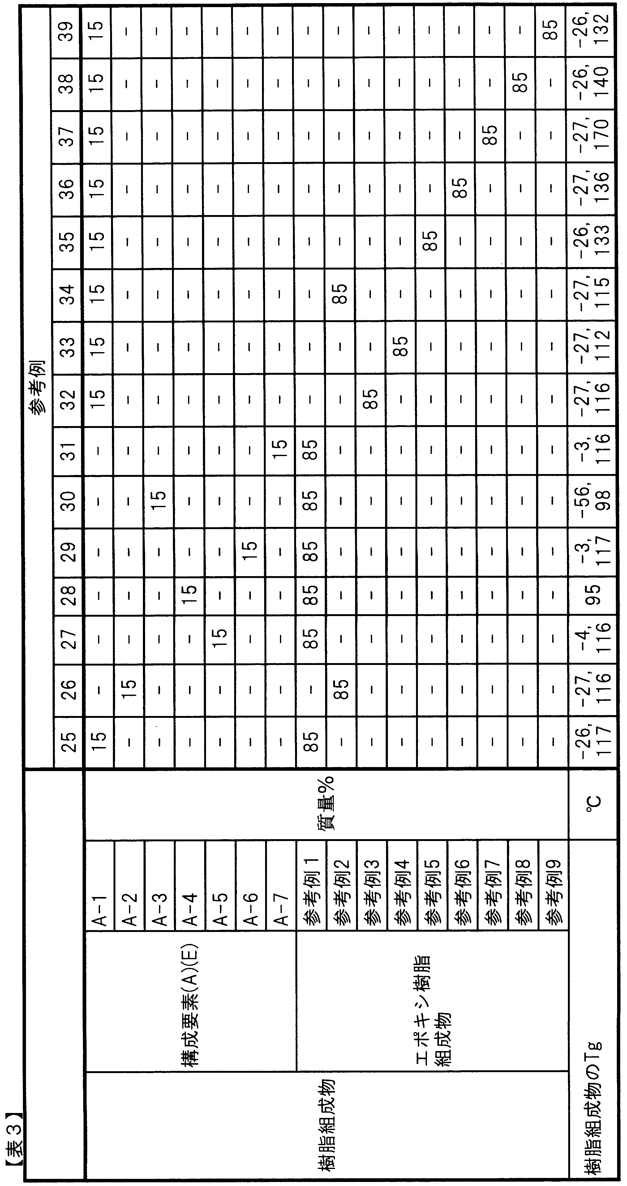
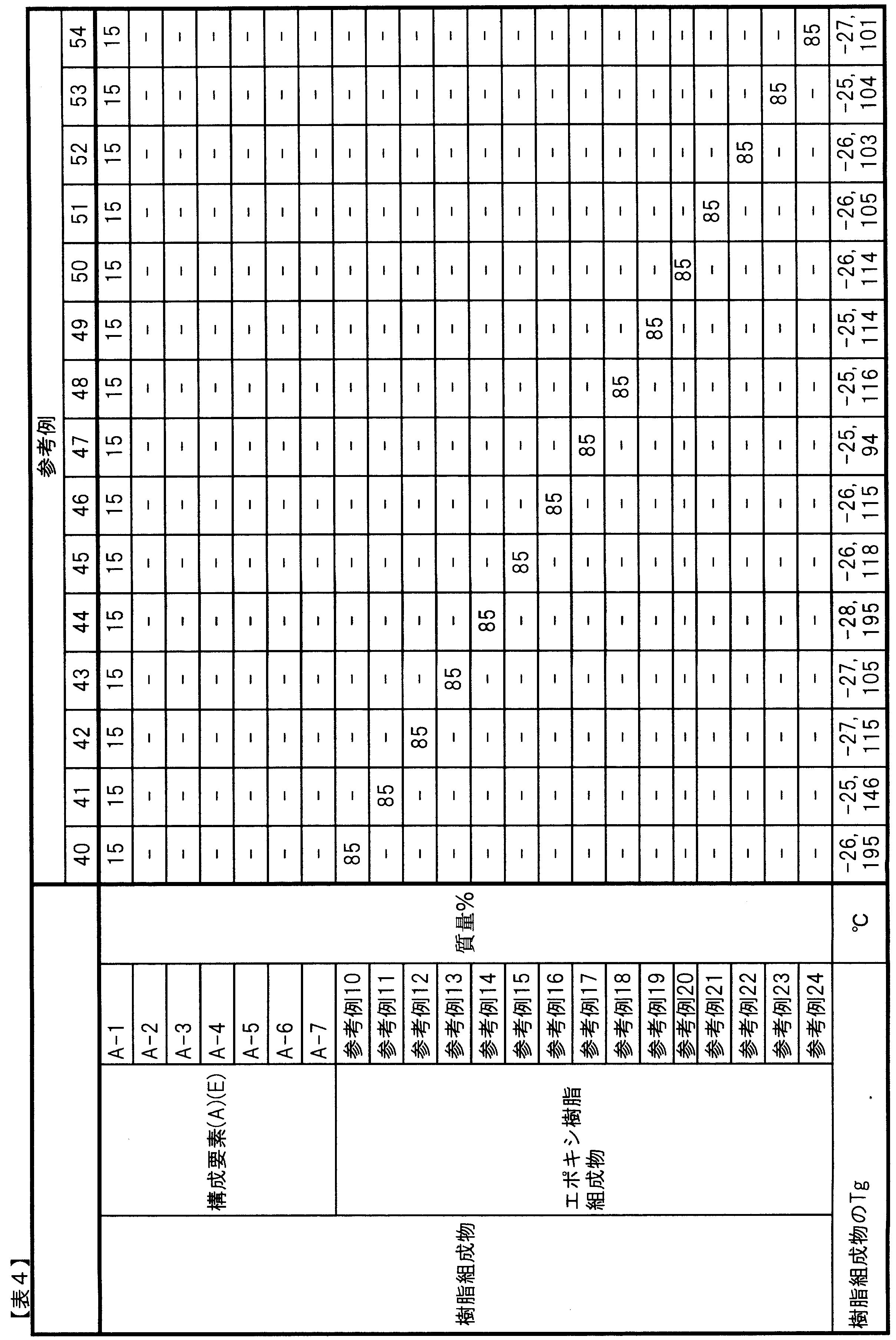


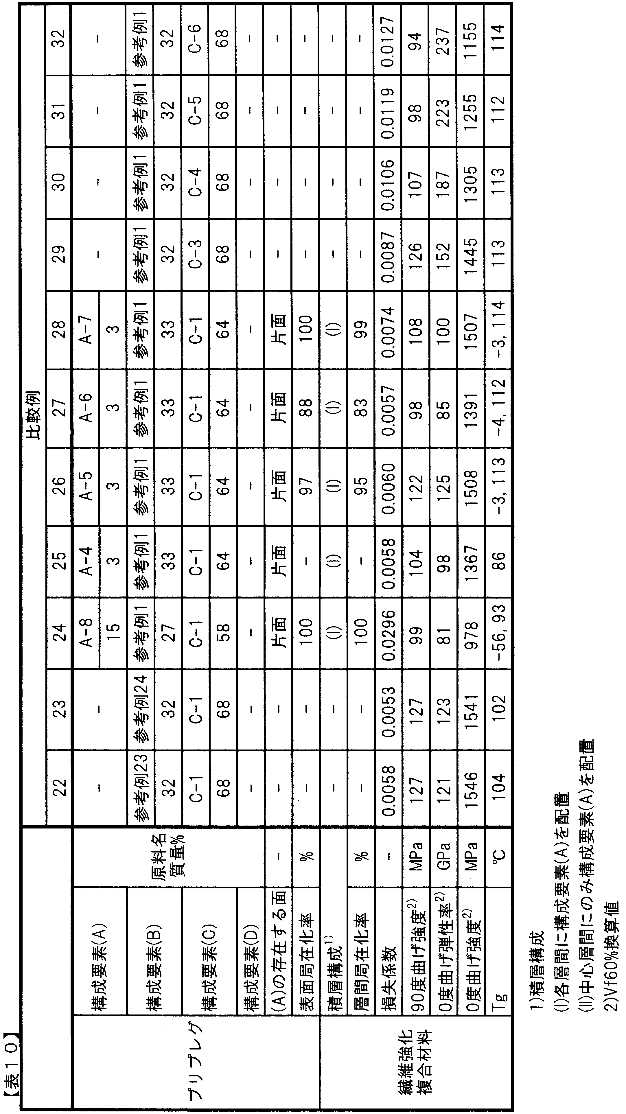

2 支持板に接していた面
3 プリプレグ厚みの20%の平行線
4 平均境界線
5 平均中心厚み線
A 構成要素(A)
B 構成要素(B)
C 構成要素(C)
D 構成要素(D)
E 構成要素(E)
F 構成要素(F)
G 構成要素(G)
H 構成要素(H)
Claims (16)
- 次の構成要素(A)~(C)を含み、構成要素(A)が、構成要素(B)および(C)からなる層の片面または両面に配置され、構成要素(A)の90面積%以上が、(A)~(C)を含むプリプレグの表面からプリプレグ平均厚みの20%までの部位に存在するプリプレグ;
(A)10℃におけるtanδが0.15以上であって、かつ、3次元架橋構造を有するウレタン粒子;
(B)第1のエポキシ樹脂組成物;
(C)強化繊維。 - 構成要素(A)が、構成要素(B)に非相溶である、請求項1に記載のプリプレグ。
- 構成要素(A)の平均粒径が、5~20μmである、請求項1または2に記載のプリプレグ。
- 構成要素(A)が、プリプレグ中に2~20質量%含まれている、請求項1~3のいずれかに記載のプリプレグ。
- 構成要素(A)が、ウレタン樹脂粒子の表面が疎水性シリカによって被覆されている粒子である、請求項1~4のいずれかに記載のプリプレグ。
- 構成要素(B)が、少なくともエポキシ当量が800~5500のエポキシ樹脂を含むエポキシ樹脂組成物である、請求項1~5のいずれかに記載のプリプレグ。
- 構成要素(C)が炭素繊維である、請求項1~6のいずれかに記載のプリプレグ。
- 構成要素(C)が、引張弾性率が230~550GPaである炭素繊維である、請求項7に記載のプリプレグ。
- 下記構成要素(D)をさらに含み、該構成要素(D)は構成要素(B)および(C)からなる層の片面または両面に配置されており、かつ、構成要素(A)が構成要素(D)に含まれた状態で存在している、請求項1~8のいずれかに記載のプリプレグ;
(D)構成要素(A)と相溶しない第2のエポキシ樹脂組成物。 - 構成要素(D)が構成要素(B)と同一である、請求項9に記載のプリプレグ。
- 請求項1~8のいずれかに記載のプリプレグを製造する方法であって、構成要素(B)を構成要素(C)に含浸させてプリプレグ前駆体を得る工程と、プリプレグ前駆体に構成要素(A)に貼付する工程を含むプリプレグの製造方法。
- 請求項9または10に記載のプリプレグを製造する方法であって、下記(I)~(III)の工程を含むプリプレグの製造方法;
(I)構成要素(A)を構成要素(D)に分散させ、これをフィルムにする工程;
(II)構成要素(B)を構成要素(C)に含浸させ、プリプレグ前駆体を作製する工程;
(III)(I)で得られたフィルムを(II)で得られたプリプレグ前駆体に貼付する工程。 - 次の構成要素(E)~(G)を含み、断面を観察した際に、構成要素(E)の90%以上が、層間領域に局在化している、繊維強化複合材料;
(E)10℃におけるtanδが0.15以上であって、かつ、3次元架橋構造を有するウレタン粒子;
(F)第3のエポキシ樹脂組成物の硬化物;
(G)強化繊維。 - 下記構成要素(H)をさらに含み、前記構成要素(E)が該構成要素(H)に含まれた状態で存在している、請求項13に記載の繊維強化複合材料;
(H)第4のエポキシ樹脂組成物の硬化物。 - 前記繊維強化複合材料の損失係数が、構成要素(E)を含まない以外は前記繊維強化複合材料と同一の繊維強化複合材料の損失係数に対して、130%以上である、請求項13または14に記載の繊維強化複合材料。
- 前記繊維強化複合材料の曲げ強度が、構成要素(E)を含まない以外は前記繊維強化複合材料と同一の繊維強化複合材料の曲げ強度に対して、90%以上である、請求項13~15のいずれかに記載の繊維強化複合材料。
Priority Applications (5)
| Application Number | Priority Date | Filing Date | Title |
|---|---|---|---|
| EP11762855.2A EP2554581B1 (en) | 2010-03-30 | 2011-03-29 | Prepreg, fiber-reinforced composite material, and method for producing prepreg |
| US13/583,476 US9139706B2 (en) | 2010-03-30 | 2011-03-29 | Prepreg, fiber-reinforced composite material, and method for producing prepreg |
| CN201180017208.9A CN102834440B (zh) | 2010-03-30 | 2011-03-29 | 预浸料坯、纤维增强复合材料及预浸料坯的制造方法 |
| JP2011514913A JP4973808B2 (ja) | 2010-03-30 | 2011-03-29 | プリプレグ、繊維強化複合材料およびプリプレグの製造方法 |
| KR1020127028062A KR101314349B1 (ko) | 2010-03-30 | 2011-03-29 | 프리프레그, 섬유 강화 복합 재료 및 프리프레그의 제조 방법 |
Applications Claiming Priority (2)
| Application Number | Priority Date | Filing Date | Title |
|---|---|---|---|
| JP2010077077 | 2010-03-30 | ||
| JP2010-077077 | 2010-03-30 |
Publications (1)
| Publication Number | Publication Date |
|---|---|
| WO2011122631A1 true WO2011122631A1 (ja) | 2011-10-06 |
Family
ID=44712326
Family Applications (1)
| Application Number | Title | Priority Date | Filing Date |
|---|---|---|---|
| PCT/JP2011/057835 Ceased WO2011122631A1 (ja) | 2010-03-30 | 2011-03-29 | プリプレグ、繊維強化複合材料およびプリプレグの製造方法 |
Country Status (7)
| Country | Link |
|---|---|
| US (1) | US9139706B2 (ja) |
| EP (1) | EP2554581B1 (ja) |
| JP (1) | JP4973808B2 (ja) |
| KR (1) | KR101314349B1 (ja) |
| CN (1) | CN102834440B (ja) |
| TW (1) | TWI447028B (ja) |
| WO (1) | WO2011122631A1 (ja) |
Cited By (3)
| Publication number | Priority date | Publication date | Assignee | Title |
|---|---|---|---|---|
| WO2012147401A1 (ja) * | 2011-04-27 | 2012-11-01 | 東レ株式会社 | プリプレグ、繊維強化複合材料およびプリプレグの製造方法 |
| GB2536255A (en) * | 2015-03-10 | 2016-09-14 | Gurit (Uk) Ltd | Moulding material for composite panels |
| WO2021132464A1 (ja) * | 2019-12-27 | 2021-07-01 | 三菱ケミカル株式会社 | プリプレグ、繊維強化複合材料、繊維強化複合材料の製造方法 |
Families Citing this family (22)
| Publication number | Priority date | Publication date | Assignee | Title |
|---|---|---|---|---|
| DE102010009528B4 (de) | 2010-02-26 | 2015-04-30 | Ifc Composite Gmbh | Blattfeder aus einem Faserverbundwerkstoff mit integrierten Lageraugen und Verfahren zur Herstellung derselben |
| DE102012016934B4 (de) * | 2012-08-27 | 2015-12-03 | Ifc Composite Gmbh | Verfahren zur gleichzeitigen Herstellung von mehreren Blattfedern aus einem Faserverbundwerkstoff |
| JP6384487B2 (ja) * | 2012-12-27 | 2018-09-05 | 東レ株式会社 | 硬質界面相を有する繊維強化ポリマー複合材料 |
| TWI602671B (zh) | 2013-01-28 | 2017-10-21 | 東邦特耐克絲歐洲股份有限公司 | 浸漬強化纖維紗及其於製造複合材料之用途 |
| JP5655976B1 (ja) * | 2013-01-28 | 2015-01-21 | 東レ株式会社 | プリプレグ、繊維強化複合材料および熱可塑性樹脂粒子 |
| US9427943B2 (en) * | 2013-03-15 | 2016-08-30 | Henkel IP & Holding GmbH | Prepreg curing process for preparing composites having superior surface finish and high fiber consolidation |
| GB2516274B (en) * | 2013-07-17 | 2016-12-28 | Gurit (Uk) Ltd | Prepreg for manufacturing composite materials |
| US20150099411A1 (en) * | 2013-09-17 | 2015-04-09 | Hanwha Azdel, Inc. | Prepregs, cores, composites and articles including repellent materials |
| JP6210007B2 (ja) * | 2014-03-26 | 2017-10-11 | 東レ株式会社 | プリプレグおよびその製造方法、ならびに炭素繊維強化複合材料 |
| JP6052421B2 (ja) * | 2014-08-06 | 2016-12-27 | 東レ株式会社 | 繊維強化熱可塑性樹脂成形材料および繊維強化熱可塑性樹脂成形品 |
| CN105709406A (zh) * | 2014-12-05 | 2016-06-29 | 黑龙江鑫达企业集团有限公司 | 一种碳纤维预浸料增强滑雪板的制备方法 |
| CN108137839B (zh) * | 2015-12-16 | 2021-07-06 | 东丽株式会社 | 预浸料坯、层压体、纤维增强复合材料、及纤维增强复合材料的制造方法 |
| KR20180097523A (ko) * | 2015-12-25 | 2018-08-31 | 도레이 카부시키가이샤 | 프리프레그 및 그 제조방법 |
| JP6793517B2 (ja) * | 2016-10-17 | 2020-12-02 | 株式会社ダイセル | シート状プリプレグ |
| KR102361346B1 (ko) * | 2017-05-24 | 2022-02-10 | 도레이 카부시키가이샤 | 섬유 강화 복합 재료용 에폭시 수지 조성물, 및 섬유 강화 복합 재료 |
| US11390719B2 (en) * | 2017-07-31 | 2022-07-19 | Toray Industries, Inc. | Sheet molding compound, prepreg, and fiber-reinforced composite material |
| CN114106369B (zh) * | 2018-04-25 | 2025-04-04 | 旭化成株式会社 | 连续纤维增强树脂成型体、及其制造方法 |
| CN110652711A (zh) * | 2018-06-28 | 2020-01-07 | 大田精密工业股份有限公司 | 复合材料高尔夫球杆头及其制造方法 |
| WO2020163798A1 (en) * | 2019-02-08 | 2020-08-13 | Ppg Industries Ohio, Inc. | Methods of coating fiber containing materials and coated fiber containing materials |
| US20220409969A1 (en) * | 2021-06-23 | 2022-12-29 | Bauer Hockey, Llc | Hockey Stick Blade and Shaft Constructs Using Boron |
| CN114957741B (zh) * | 2021-12-29 | 2024-01-02 | 江苏志纤复能科技有限公司 | 一种低温共固化高阻尼复合材料及其制备方法 |
| CN116021800A (zh) * | 2023-01-10 | 2023-04-28 | 上纬新材料科技股份有限公司 | 一种用于改善打孔叶片壳体根部裂纹的固化工艺 |
Citations (11)
| Publication number | Priority date | Publication date | Assignee | Title |
|---|---|---|---|---|
| JPS63162732A (ja) * | 1986-12-25 | 1988-07-06 | Toray Ind Inc | プリプレグ |
| JPS63170427A (ja) * | 1987-01-07 | 1988-07-14 | Toray Ind Inc | 繊維強化プリプレグの製造方法 |
| JPS63170428A (ja) * | 1987-01-07 | 1988-07-14 | Toray Ind Inc | プリプレグの製造方法 |
| JPS6426651A (en) * | 1987-01-06 | 1989-01-27 | Toray Industries | Production of prepreg |
| JPH01104624A (ja) | 1987-10-16 | 1989-04-21 | Toray Ind Inc | 樹脂微粒子を用いたプリプレグ |
| JPH04207139A (ja) | 1990-11-30 | 1992-07-29 | Toray Ind Inc | 釣竿 |
| JPH0741577A (ja) * | 1993-07-30 | 1995-02-10 | Toray Ind Inc | プリプレグおよび繊維強化プラスチック |
| JPH08283435A (ja) | 1995-02-14 | 1996-10-29 | Toray Ind Inc | ヤーンプリプレグおよび繊維強化複合材料 |
| JP2003012889A (ja) | 2001-06-27 | 2003-01-15 | Mitsubishi Rayon Co Ltd | エポキシ樹脂組成物及びそれを用いたテニスラケット |
| JP2008237373A (ja) | 2007-03-26 | 2008-10-09 | Mrc Composite Products Co Ltd | ゴルフクラブシャフトとそのシャフトの製造方法 |
| JP2009261473A (ja) | 2008-04-22 | 2009-11-12 | Yokohama Rubber Co Ltd:The | ゴルフクラブシャフト |
Family Cites Families (16)
| Publication number | Priority date | Publication date | Assignee | Title |
|---|---|---|---|---|
| US4474852A (en) * | 1983-05-23 | 1984-10-02 | Thomas B. Crane | Hydrophobic colloidal oxide treated core material, method of production and composition comprised thereof |
| ES2051274T3 (es) | 1986-12-25 | 1994-06-16 | Toray Industries | Materiales compuestos altamente resistentes. |
| JPS63203327A (ja) * | 1987-02-19 | 1988-08-23 | 株式会社シマノ | 管状体 |
| JPH0527783A (ja) | 1991-01-24 | 1993-02-05 | Toray Ind Inc | 音質変更板 |
| JPH06136320A (ja) * | 1992-10-26 | 1994-05-17 | Mitsubishi Kasei Corp | 透湿防水性被覆成形物の製造法 |
| JPH0985844A (ja) | 1995-07-18 | 1997-03-31 | Toray Ind Inc | 繊維強化プラスチック製管状体 |
| DE69611453T2 (de) * | 1995-08-24 | 2001-08-23 | Minnesota Mining And Mfg. Co., Saint Paul | Verfahren zur herstellung von partikel-beschichtetem festen substrat |
| JPH09216958A (ja) * | 1996-02-08 | 1997-08-19 | Nippon Oil Co Ltd | プリプレグ |
| DE59711794D1 (de) * | 1996-09-26 | 2004-08-26 | Siemens Ag | Epoxidharzmischungen |
| JPH11217734A (ja) * | 1997-11-21 | 1999-08-10 | Toray Ind Inc | 炭素繊維およびその製造方法 |
| JP2000281747A (ja) * | 1999-03-30 | 2000-10-10 | Nippon Mitsubishi Oil Corp | 複合材料用エポキシ樹脂組成物 |
| JP2004149979A (ja) * | 2002-10-31 | 2004-05-27 | Toho Tenax Co Ltd | 炭素繊維ストランド |
| US7208228B2 (en) | 2003-04-23 | 2007-04-24 | Toray Composites (America), Inc. | Epoxy resin for fiber reinforced composite materials |
| JP4096198B2 (ja) | 2004-06-09 | 2008-06-04 | 美津濃株式会社 | ゴルフボール形成用組成物及びマルチピースゴルフボール |
| JP2008050587A (ja) | 2006-07-25 | 2008-03-06 | Toray Ind Inc | プリプレグおよび複合材料 |
| US8080313B2 (en) | 2009-05-28 | 2011-12-20 | Cytec Technology Corp. | Particle-toughened fiber-reinforced polymer composites |
-
2011
- 2011-03-29 EP EP11762855.2A patent/EP2554581B1/en not_active Not-in-force
- 2011-03-29 WO PCT/JP2011/057835 patent/WO2011122631A1/ja not_active Ceased
- 2011-03-29 CN CN201180017208.9A patent/CN102834440B/zh not_active Expired - Fee Related
- 2011-03-29 US US13/583,476 patent/US9139706B2/en not_active Expired - Fee Related
- 2011-03-29 JP JP2011514913A patent/JP4973808B2/ja active Active
- 2011-03-29 KR KR1020127028062A patent/KR101314349B1/ko not_active Expired - Fee Related
- 2011-03-30 TW TW100110950A patent/TWI447028B/zh not_active IP Right Cessation
Patent Citations (11)
| Publication number | Priority date | Publication date | Assignee | Title |
|---|---|---|---|---|
| JPS63162732A (ja) * | 1986-12-25 | 1988-07-06 | Toray Ind Inc | プリプレグ |
| JPS6426651A (en) * | 1987-01-06 | 1989-01-27 | Toray Industries | Production of prepreg |
| JPS63170427A (ja) * | 1987-01-07 | 1988-07-14 | Toray Ind Inc | 繊維強化プリプレグの製造方法 |
| JPS63170428A (ja) * | 1987-01-07 | 1988-07-14 | Toray Ind Inc | プリプレグの製造方法 |
| JPH01104624A (ja) | 1987-10-16 | 1989-04-21 | Toray Ind Inc | 樹脂微粒子を用いたプリプレグ |
| JPH04207139A (ja) | 1990-11-30 | 1992-07-29 | Toray Ind Inc | 釣竿 |
| JPH0741577A (ja) * | 1993-07-30 | 1995-02-10 | Toray Ind Inc | プリプレグおよび繊維強化プラスチック |
| JPH08283435A (ja) | 1995-02-14 | 1996-10-29 | Toray Ind Inc | ヤーンプリプレグおよび繊維強化複合材料 |
| JP2003012889A (ja) | 2001-06-27 | 2003-01-15 | Mitsubishi Rayon Co Ltd | エポキシ樹脂組成物及びそれを用いたテニスラケット |
| JP2008237373A (ja) | 2007-03-26 | 2008-10-09 | Mrc Composite Products Co Ltd | ゴルフクラブシャフトとそのシャフトの製造方法 |
| JP2009261473A (ja) | 2008-04-22 | 2009-11-12 | Yokohama Rubber Co Ltd:The | ゴルフクラブシャフト |
Non-Patent Citations (1)
| Title |
|---|
| See also references of EP2554581A4 |
Cited By (7)
| Publication number | Priority date | Publication date | Assignee | Title |
|---|---|---|---|---|
| WO2012147401A1 (ja) * | 2011-04-27 | 2012-11-01 | 東レ株式会社 | プリプレグ、繊維強化複合材料およびプリプレグの製造方法 |
| GB2536255A (en) * | 2015-03-10 | 2016-09-14 | Gurit (Uk) Ltd | Moulding material for composite panels |
| GB2536255B (en) * | 2015-03-10 | 2017-11-01 | Gurit (Uk) Ltd | Moulding material for composite panels |
| US10870240B2 (en) | 2015-03-10 | 2020-12-22 | Gurit (Uk) Ltd. | Moulding material for composite panels |
| WO2021132464A1 (ja) * | 2019-12-27 | 2021-07-01 | 三菱ケミカル株式会社 | プリプレグ、繊維強化複合材料、繊維強化複合材料の製造方法 |
| JPWO2021132464A1 (ja) * | 2019-12-27 | 2021-07-01 | ||
| JP7616076B2 (ja) | 2019-12-27 | 2025-01-17 | 三菱ケミカル株式会社 | プリプレグ、繊維強化複合材料、繊維強化複合材料の製造方法 |
Also Published As
| Publication number | Publication date |
|---|---|
| CN102834440A (zh) | 2012-12-19 |
| KR101314349B1 (ko) | 2013-10-04 |
| KR20120125404A (ko) | 2012-11-14 |
| CN102834440B (zh) | 2014-04-02 |
| US9139706B2 (en) | 2015-09-22 |
| JP4973808B2 (ja) | 2012-07-11 |
| US20120328858A1 (en) | 2012-12-27 |
| EP2554581A4 (en) | 2013-08-28 |
| TW201202046A (en) | 2012-01-16 |
| EP2554581B1 (en) | 2014-08-13 |
| EP2554581A1 (en) | 2013-02-06 |
| TWI447028B (zh) | 2014-08-01 |
| JPWO2011122631A1 (ja) | 2013-07-08 |
Similar Documents
| Publication | Publication Date | Title |
|---|---|---|
| JP4973808B2 (ja) | プリプレグ、繊維強化複合材料およびプリプレグの製造方法 | |
| JP4985877B2 (ja) | プリプレグ、繊維強化複合材料およびプリプレグの製造方法 | |
| JP5354095B2 (ja) | プリプレグ、繊維強化複合材料およびプリプレグの製造方法 | |
| TWI435887B (zh) | 環氧樹脂組成物、預浸透物及纖維強化複合材料 | |
| TWI447139B (zh) | 環氧樹脂組成物、預浸漬物及纖維強化複合材料 | |
| JP5648679B2 (ja) | 繊維強化複合材料用エポキシ樹脂組成物、プリプレグおよび繊維強化複合材料 | |
| JP5747763B2 (ja) | エポキシ樹脂組成物、プリプレグおよび繊維強化複合材料 | |
| JP6131593B2 (ja) | プリプレグおよび繊維強化複合材料 | |
| JP2010059225A (ja) | 炭素繊維強化複合材料用エポキシ樹脂組成物、プリプレグおよび炭素繊維強化複合材料 | |
| JP2014167103A (ja) | エポキシ樹脂組成物、プリプレグおよび繊維強化複合材料 | |
| JP2014167102A (ja) | エポキシ樹脂組成物、プリプレグおよび繊維強化複合材料 | |
| JP2012196921A (ja) | 繊維強化複合材料、およびその製造方法 | |
| JP5326435B2 (ja) | エポキシ樹脂組成物、プリプレグ、および、繊維強化複合材料、ならびに、繊維強化複合材料の製造方法 |
Legal Events
| Date | Code | Title | Description |
|---|---|---|---|
| WWE | Wipo information: entry into national phase |
Ref document number: 201180017208.9 Country of ref document: CN |
|
| WWE | Wipo information: entry into national phase |
Ref document number: 2011514913 Country of ref document: JP |
|
| 121 | Ep: the epo has been informed by wipo that ep was designated in this application |
Ref document number: 11762855 Country of ref document: EP Kind code of ref document: A1 |
|
| WWE | Wipo information: entry into national phase |
Ref document number: 2011762855 Country of ref document: EP |
|
| WWE | Wipo information: entry into national phase |
Ref document number: 13583476 Country of ref document: US |
|
| NENP | Non-entry into the national phase |
Ref country code: DE |
|
| ENP | Entry into the national phase |
Ref document number: 20127028062 Country of ref document: KR Kind code of ref document: A |