WO2011125237A1 - データベース管理方法、計算機、センサネットワークシステム及びデータベース検索プログラム - Google Patents
データベース管理方法、計算機、センサネットワークシステム及びデータベース検索プログラム Download PDFInfo
- Publication number
- WO2011125237A1 WO2011125237A1 PCT/JP2010/062343 JP2010062343W WO2011125237A1 WO 2011125237 A1 WO2011125237 A1 WO 2011125237A1 JP 2010062343 W JP2010062343 W JP 2010062343W WO 2011125237 A1 WO2011125237 A1 WO 2011125237A1
- Authority
- WO
- WIPO (PCT)
- Prior art keywords
- data
- time
- query
- database
- inquiry
- Prior art date
- Legal status (The legal status is an assumption and is not a legal conclusion. Google has not performed a legal analysis and makes no representation as to the accuracy of the status listed.)
- Ceased
Links
Images


















Classifications
-
- G—PHYSICS
- G05—CONTROLLING; REGULATING
- G05B—CONTROL OR REGULATING SYSTEMS IN GENERAL; FUNCTIONAL ELEMENTS OF SUCH SYSTEMS; MONITORING OR TESTING ARRANGEMENTS FOR SUCH SYSTEMS OR ELEMENTS
- G05B23/00—Testing or monitoring of control systems or parts thereof
- G05B23/02—Electric testing or monitoring
- G05B23/0205—Electric testing or monitoring by means of a monitoring system capable of detecting and responding to faults
- G05B23/0259—Electric testing or monitoring by means of a monitoring system capable of detecting and responding to faults characterized by the response to fault detection
- G05B23/0283—Predictive maintenance, e.g. involving the monitoring of a system and, based on the monitoring results, taking decisions on the maintenance schedule of the monitored system; Estimating remaining useful life [RUL]
-
- G—PHYSICS
- G06—COMPUTING OR CALCULATING; COUNTING
- G06F—ELECTRIC DIGITAL DATA PROCESSING
- G06F16/00—Information retrieval; Database structures therefor; File system structures therefor
- G06F16/20—Information retrieval; Database structures therefor; File system structures therefor of structured data, e.g. relational data
- G06F16/24—Querying
- G06F16/245—Query processing
-
- G—PHYSICS
- G06—COMPUTING OR CALCULATING; COUNTING
- G06F—ELECTRIC DIGITAL DATA PROCESSING
- G06F16/00—Information retrieval; Database structures therefor; File system structures therefor
- G06F16/20—Information retrieval; Database structures therefor; File system structures therefor of structured data, e.g. relational data
- G06F16/24—Querying
- G06F16/245—Query processing
- G06F16/2458—Special types of queries, e.g. statistical queries, fuzzy queries or distributed queries
- G06F16/2474—Sequence data queries, e.g. querying versioned data
Definitions
- the present invention relates to a computer system for performing data processing and a data processing method thereof, and in particular, a computer system suitable for processing a large amount of data collected for the purpose of preventive maintenance such as equipment in a factory or a plant. It relates to the data processing method.
- the above-described method has a problem in that when searching for compressed data, it is necessary to search the data after being decompressed once, and the retrieval speed is sacrificed.
- a search query for searching for an abnormal part from the sensor information and a search query for tracking the abnormal part in order to specify the cause of the abnormality are issued multiple times. There was a need. Therefore, there are problems that the number of issued queries increases and the search time for abnormal parts increases.
- the present invention has been made in view of the above-mentioned problems. That is, the object is to reduce the amount of data stored in a database and to efficiently search for desired data from a large amount of data.
- a typical example of the present invention is as follows. That is, a database management method in a computer that includes a processor and a memory connected to the processor and manages a database, wherein the database stores a plurality of compressed data compressed based on a predetermined condition,
- the database management method when a query to the database is received from a client computer connected to the computer, the computer analyzes the received query, and the computer receives the query.
- a fourth step of acquiring one or more compressed data as a response result of one inquiry, and the computer decompressing one or more compressed data acquired as a response result to the first inquiry A fifth step of acquiring the plurality of time-series data; a sixth step in which the computer executes the second inquiry on the acquired plurality of time-series data; and the computer, Based on a response result to the second inquiry, a seventh step of extracting predetermined data from the plurality of acquired time-series data. And an eighth step in which the computer extracts data for output to the client computer from the predetermined data extracted in the seventh step, and generates an output result. .
- the present invention it is possible to reduce the amount of data stored in the database while maintaining substantial data, and to efficiently search for desired data from a large amount of data.
- it is a flowchart explaining the case where the process performed by the data search module is performed in parallel.
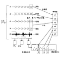
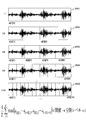
- It is a figure explaining the kind and generation method of the feature value of embodiment of this invention.
- It is a figure explaining the method to determine the time width of the time-sequential data block of embodiment of this invention.
- It is a flowchart explaining an example of the process performed by the stream data processing part of this embodiment.
- It is a flowchart explaining an example of the process performed by the output control part of this embodiment.
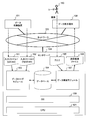
- FIG. 1 is a block diagram illustrating an outline of a computer system in an embodiment of a sensor network system to which the present invention is applied.
- the sensor network system includes a plant 102, a data center 105, and a plant monitoring site 107, and is connected to each other via a network 103.
- a network 103 for example, a dedicated line, a wide area network such as the so-called Internet, or a local network such as a LAN may be used.
- the plant 102 includes a sensor 100 and a data collection device 101.
- the sensor 100 and the data collection device 101 are connected to each other.
- the connection method may be direct connection, or may be connected via a LAN (Local Area Network) or a wireless network.
- the Sensor 100 detects various data.
- the sensor 100 includes various types of sensors in order to detect target data.
- the data collection device 101 collects data detected by the sensor 100 and transmits the data collected from the sensor 100 to the data center 105 via the network 103.
- the data collection device 101 includes a CPU (not shown), a memory (not shown) connected to the CPU, a network interface (not shown) connected to the CPU, and a storage medium (not shown).
- the data collection device 101 may include a display or an input device.
- the data center 105 includes a center server 104 that centrally manages data transmitted from the data collection devices 101 of the plurality of plants 102.
- the center server 104 stores the data transmitted from the data collection device 101.
- the center server 104 extracts predetermined data from the stored data based on a request from the administrator via the plant monitoring site 107 or the like, or analyzes the extracted data and outputs an analysis result.
- the plant monitoring site 107 includes a data display terminal 106 for making various inquiries to the data center 105.
- the data display terminal 106 monitors or browses data stored in the center server 104 via the network 103.
- the data display terminal 106 includes a CPU (not shown), a memory (not shown) connected to the CPU, a network interface (not shown) connected to the CPU, a storage medium (not shown), a display device (not shown), An input device (not shown) is provided.
- FIG. 2 is a block diagram illustrating a hardware configuration of the center server 104 in the present embodiment.
- the center server 104 includes a CPU 121, a memory 122, an HDD 123, a display 124, a network interface 125, a mouse 126, a keyboard 127, and a power supply device 128.
- CPU 121 executes a program developed on memory 122.
- the memory 122 stores a program executed by the CPU 121 and information necessary for executing the program.
- the memory 122 is used as a work area for the CPU to execute various processes.
- programs such as the OS 158 (see FIG. 3), the data loader module 153 (see FIG. 3), the database 154 (see FIG. 3), and the data search module 157 (see FIG. 3) are loaded from the HDD 123 onto the memory 122. And executed.
- the HDD 123 stores programs and various information read to the memory 122.
- only one HDD 123 is provided, but a plurality of HDDs 123 may be provided, or an array group including a plurality of HDDs 123 may be used.
- the network interface 125 is an interface for connecting to the network 103.
- the power supply device 128 is a device for supplying power to the center server 104.
- the display 124 is a device that displays various types of information to an operator who operates the center server 104.
- the mouse 126 is a pointing device used by an operator who operates the center server 104.
- the keyboard 127 is an input device used by an operator who operates the center server 104.
- FIG. 3 is a block diagram illustrating the software configuration of the center network system in the present embodiment.
- an OS (Operating System) 158 is executed by the CPU 121.
- the OS 158 executes various processes. Specifically, the OS 158 executes a data loader module 153, a database 154, and a data search module 157.
- the database 154 is management software that manages data transmitted from the data collection device 101 and converted into a predetermined format by the data loader module 153. Details of data stored in the database 154 will be described later with reference to FIG.
- the data loader module 153 is software that receives data from the data collection device 101 included in the plant 102 via the network 103, converts the received data into a predetermined format, and stores the data in a database.
- the data loader module 153 receives the input file 1 (151) with the file name “sid.csv” from the data collection device 101 and the input file 2 (152) with the file name “input.csv”. ), The input file 1 (151) and the input file 2 (152) are converted into a predetermined format and stored in the database 154.
- the file 1 (151) and the file 2 (152) shown in FIG. 3 are CSV (Comma Separated Value) format files.
- the CSV file represents a file format in which a plurality of fields are separated by “, (comma)”.
- FIG. 3 shows an example in which the CSV format is used, but a file format (TSV format) or a binary format separated by TAB may be used instead of commas.
- the data search module 157 is software that searches the target data from the database 154 based on the input query and outputs the search result.
- the data search module 157 receives a query 155 from the user 150 who operates the data display terminal 106, searches for data based on the query 155, and sets the search result file 156 as the search result file 156. Output.
- the data display terminal 106 reads the search result file 156, converts the data into a number or a form such as a graphical waveform, and displays it on the screen.
- FIG. 4 is a block diagram illustrating the data loader module 153 and the database 154 in the present embodiment.
- the input file 1 includes a Name column 1511 and an ID column 1512.
- the Name column 1511 is a sensor name of the sensor 100 provided in the plant 102.
- the ID column 1512 is an identifier for uniquely identifying the sensor 100 provided in the plant 102.
- the input file 2 includes a Datetime column 1521 and a sensor name column 1522.
- the Datetime column 1521 is time information indicating the time when the sensor 100 acquires data.
- the sensor name column 1522 includes names of the respective sensors 100, and sensor names corresponding to the Name column 1511 are stored. Each sensor 100 constituting the sensor name column 1522 stores a value detected by each sensor 100.
- the input file 2 (152) stores data detected by each sensor 100 every second.
- the database 154 stores an SID table 207 and a DAT table 208.
- the SID table 207 includes a Name column 2071 and an ID column 2072.
- Name column 2071 is a sensor name of sensor 100 provided in plant 102.
- the ID column 2072 is an identifier for uniquely identifying the sensor 100 provided in the plant 102.
- the DAT table 208 stores data obtained by compressing the data included in the input file 2 (152) for each predetermined continuous time unit (time-series data block) for each sensor 100. Specifically, compressed data for one hour is stored for each sensor 100 for each row.
- the DAT table 208 includes a Datetime column 2081, an ID column 2082, a CDATA column 2083, a MaxVal column 2084, and a MinVal column 2085.
- the Datetime column 2081 stores time information indicating the start time of the compressed time-series data block.
- the head time represents the past time in the Datetime column 1521, that is, the time that is the starting point of the time-series data block to be compressed.
- the ID column 2082 is an identifier for identifying the sensor 100.
- the CDATA column 2083 is compressed data.
- the MaxVal column 2084 is the maximum value of data included in the compressed time series data block.
- the MinVal column 2085 is a minimum value included in the compressed time series data block.
- the time series data block compressed for the data group 201 corresponds to the row 209
- the time series data block compressed for the data group 202 corresponds to the row 210.
- row 209 is data “DDD” obtained by compressing data for one hour from “00: 00: 00: 00 of 2009/10/1” for the sensor 100 with the sensor name “S4”.
- the maximum value included in the data is “99”, and the minimum value included in the data before compression is “52”.
- 3600 lines (1 hour) of data in the input file 2 (152) is compressed into one line.
- the time range stored in the time series data block is fixed to 1 hour, but the time range of the time series data block may be changed to other than 1 hour.
- the search period most used by the user is used. For example, a period of 1/10 of the most frequently searched period is set as the time range of the time-series data block.
- the search range is 1 day
- the time range of the time series data block is 2.4 hours
- the search range is 1 month
- the time range of the time series data block is 3 days. This can be realized by calculating the time range from the search period specified in the where_timerrange clause of the query example 1 in FIG. 8A in the query analysis unit of the data search module 157 and managing the time range as a frequency table. It becomes.
- a minimum period in which a time series feature change can be used.
- a method of dividing the time series data block 2601 and making the time series block 2605 an optimum time series block will be described with reference to FIG.
- FIG. 26 is a diagram illustrating a method for determining a time width of a time-series data block according to the embodiment of this invention.
- the feature value a [1] [1] is obtained.
- the time series data block is divided in half to obtain feature values a [2] [1], a [2] [2].
- i represents a division level indicating how many times the division is performed
- j represents a number indicating the feature value of the time-series data block.
- the optimal division level of the time-series data block is set, and the width of the time-series data block is set to the optimal time range.
- the value having the larger difference between the feature values a [i] [j] and a [i + 1] [j] and a [i] [j] and a [i + 1] [j + 1] is assigned to all time-series data blocks j. It is also possible to take an average for this and determine this value as a “difference from the feature value” to determine the threshold value.
- the storage capacity of the database can be reduced by storing the compressed data.
- the data loader module 153 includes a data aggregation unit 203, a feature value extraction unit 204, a feature value extraction stream data processing unit 2041, a data compression unit 205, and a data insertion unit 206.
- the data aggregating unit 203 aggregates data for each sensor 100 at a predetermined time interval (1 hour in the present embodiment).
- the feature value extraction unit 204 extracts feature values from the compressed data.
- the feature value is used when retrieving compressed data from the database 154.
- a search method using feature values will be described later with reference to FIG.
- the maximum value and the minimum value are extracted as feature values from the data to be compressed.
- the extracted feature value may be any value as long as it is a value indicating the feature of the data to be compressed, such as average or variance.
- the maximum value, the minimum value, the average value, the variance value, or the standard deviation value with respect to the time series of the entire compressed data or an arbitrary section is used as the feature amount.
- an average value of a plurality of sensor observation values i3 and i4 is used as a feature value.
- the entire compressed data or an arbitrary section is framed and converted to a frequency band by performing FFT (Fast Fourier Transform), and at predetermined frequencies A, B, and C. Amplitude is used as a feature value.
- FFT Fast Fourier Transform
- the feature value extraction unit 204 can generate a feature value by using the feature value extraction stream data processing unit 2041. That is, time-series data that arrives in real time is accumulated in a memory for a predetermined period, and a feature value can be generated by performing time-series analysis such as a maximum value, a minimum value, an average value, or a variance value.
- the data compression unit 205 compresses data at a predetermined time interval for each sensor.
- the data insertion unit 206 stores the compressed data in the DAT table 208.
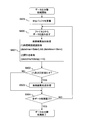
- FIG. 5A is a flowchart illustrating processing executed by the data loader module 153 in the present embodiment.
- the data loader module 153 determines whether or not the SID table 207 exists in the database 154 (S250). For example, the data loader module 153 can make the determination by issuing an SQL for inquiring the database 154 about the existence of the SID table 207.
- the data loader module 153 proceeds to S252.
- the data loader module 153 reads the input file 1 (151) and generates the SID table 207 (S251).
- the data loader module 153 reads a character string for one line from the input file 2 (152), extracts a character string corresponding to the column from the character string read with a comma as a delimiter, and stores it in the array csv ( S252). For example, when ci character strings are extracted, the extracted character strings are stored in arrays csv [0] to csv [ci-1], respectively. Here, ci represents the number of columns. In this embodiment, datetime is stored in csv [0], and sensor values are stored in csv [1] to csv [ci-1].
- the data loader module 153 generates an array id for enabling the ID column 2082 to be searched from the sensor name column 1522 of the input file 2 (152) (S253).
- the data loader module 153 defines a data array for creating compressed data (S254).
- a d [ci] [3600] array is defined. That is, 3600 arrays are defined for one sensor 100.
- the data loader module 153 determines whether or not the DAT table 208 exists in the database 154 (S255). For example, the data loader module 153 can make a determination by issuing an SQL querying the database 154 about the existence of the DAT table 208.
- the data loader module 153 proceeds to S257.
- the data loader module 153 If it is determined that the DAT table 208 does not exist in the database 154, the data loader module 153 generates the DAT table 208 (S256).
- the data loader module 153 generates compressed data from the array acquired in S254 and executes a data load process for storing in the DAT table 208 (S257). Details of the data loading process will be described later with reference to FIG. 5B.
- the data loader module 153 determines whether or not the processing has been completed for all data in the input file 2 (152) (S258).
- the data loader module 153 returns to S257 and executes similar processing.
- the data loader module 153 terminates the processing.
- 5B and 5C are flowcharts for explaining the data load process executed by the data loader module 153 in the present embodiment.
- the data loader module 153 initializes a variable i indicating time (seconds), and executes processing for all times (seconds) (S259). Specifically, the data loader module 153 sets the variable i to “0” and repeatedly executes the process until the variable i becomes larger than “3600”. In the present embodiment, data from 0 to 3599 seconds is a processing target.
- the data loader module 153 reads one line of data from the input file 2 (152), extracts ci character strings from the read data, and stores them in the arrays csv [0] to csv [ci-1]. (S260).
- the data loader module 153 determines whether or not the variable i is “0” (S261).
- the data loader module 153 stores csv [0] in the Datetime column 2081 of the DAT table 208 (S262).
- the data loader module 153 collects data for each sensor 100 (S263). Specifically, the data aggregating unit 203 digitizes values stored in the array csv and sets them in the array d.
- the data loader module 153 determines whether to repeatedly execute the process, that is, whether the process has been completed for all the times (S264).
- the data loader module 153 returns to S259, adds “1” to the variable i, and executes the processing from S260 to S263.
- the data loader module 153 initializes a variable j representing the number of sensors 100 and executes the processing for all the sensors 100 (S265). Specifically, the data loader module 153 sets “1” to the variable j, and repeatedly executes the process until the variable j becomes larger than cn.
- the data loader module 153 extracts feature values from the array d [j] [i] (S266). Specifically, the feature value extraction unit 204 selects the maximum value, minimum value, average value, variance value, or specific value on the frequency spectrum from the arrays d [j] [0] to d [j] [3599]. Either one or a combination thereof is extracted.
- the data loader module 153 compresses the array d [j] [i] into a predetermined format (S267). Specifically, the data compression unit 205 compresses the arrays d [j] [0] to d [j] [3599] into a predetermined format.
- a compression format zip, lzh, gzip, bzip2, etc. can be considered.
- the data loader module 153 stores the compressed data in the DAT table 208 (S268). Specifically, the data insertion unit 206 sets id [i] generated in S253 to the ID column 2082, csv [0] set in S262 to the Datetime column 2081, and sets the maximum value extracted in S266 to DAT. The minimum value extracted in S266 is stored in the MinVal column 2085, and the data compressed in S267 is stored in the CDATA 2083 in the MaxVal column 2084 of the table 208.
- the data loader module 153 determines whether or not the processing has been completed for all the sensors 100 (S269).
- the data loader module 153 returns to S266 and executes the same processing.
- the data loader module 153 ends the processing.
- FIG. 6 is a block diagram illustrating the data search module 157 in the present embodiment.
- the data search module 157 issues an SQL to the database 154 based on the input query 155, generates a search result based on a response to the issued SQL, and outputs the generated search result to the search result file 156. To do.
- the data search module 157 includes a query analysis unit 300, an SQL generation unit 301, a feature value search SQL generation unit 302, a CQL generation unit 303, a DB search unit 304, a data decompression / sorting processing unit 305, a stream data processing unit 306, A cutout processing unit 307 and a data output unit 308 are provided.
- the query analysis unit 300 analyzes the input query 155 and outputs the content of the query 155 as a global variable 309.
- the global variable 309 is stored in a storage area such as the memory 122, and includes an SQL generation unit 301, a feature value search SQL generation unit 302, a CQL generation unit 303, a DB search unit 304, a data decompression / sorting processing unit 305, Each unit of the stream data processing unit 306, the cutout processing unit 307, and the data output unit 308 can be referred to.
- the SQL generation unit 301 generates an SQL 310 for searching the database 154 based on the global variable 309 that is an analysis result of the query analysis unit 300, and outputs the generated SQL 310 to the DB search unit 304.
- the feature value search SQL generation unit 302 Based on the global variable 309 that is the analysis result of the query analysis unit 300, the feature value search SQL generation unit 302 generates a SQL 310 for searching the database 154 using the feature value, and performs a DB search for the generated SQL 310. Output to the unit 304.
- the CQL generation unit 303 generates a CQL 311 for executing stream data processing based on the global variable 309 that is the analysis result of the query analysis unit 300, and outputs the generated CQL 311 to the stream data processing unit 306.
- the DB search unit 304 issues the SQL 310 generated by the SQL generation unit 301 or the feature value search SQL generation unit 302 to the database 154.
- the DB search unit 304 outputs the execution result of the SQL 310, that is, the data search result to the file A312. Note that the data output to the file A 312 is compressed data.
- the data decompressing / sorting processing unit 305 reads the file A 312, decompresses the compressed data, and sorts the decompressed data based on a predetermined condition.
- the data decompressing / sorting processing unit 305 outputs the processed data to the file B313.
- the stream data processing unit 306 reads the file B 313 as input data based on the CQL 311 generated by the CQL generation unit 303, and executes stream data processing on each read data.
- the stream data processing unit 306 outputs the processed data to the file C314.
- the cutout processing unit 307 extracts data that matches a predetermined condition from the file C314.
- the cutout processing unit 307 outputs the data extracted to the file D315.
- the data output unit 308 generates an output result using the data stored in the file D315, and outputs the generated output result as a search result file 156.
- FIG. 7 is an explanatory diagram showing an example of the structure of data output by the data search module 157 in the present embodiment.
- Data structure 1 is a data structure of data (packet) stored in file A312.
- File A 312 stores a plurality of packets.
- the data structure 1 (340) includes datetime 3401, idx3402, zlen3403, and zblk3404.
- Datetime 3401 represents time such as date and time, and corresponds to the Datetime column 2081 of the DAT table 208.
- the data length of datetime 3401 is 8 bytes.
- Idx3402 represents a sensor identification number for identifying the sensor 100.
- the arrangement order of the sensors described in the input_item clause of the query example 1 is assigned as a sensor identification number.
- the data length of idx3402 is 4 bytes.
- Zlen 3403 represents the block length of the compressed data, and in this embodiment, the data length is 4 bytes.
- Zblk 3404 represents compressed data. Specifically, the compressed data itself. In the present embodiment, the data length of zblk 3404 is nbytes.
- Data structure 2 (341) is a data structure of data (binary) stored in the file B313, the file C314, and the file D315.
- Datetime 3411 represents time such as date and time.
- the data length of datetime 3411 is 8 bytes.
- Valn 3412 represents the number of data 3413, and in this embodiment, the data length is 8 bytes.
- the data 3413 represents values calculated by the data decompression / sorting processing unit 305, the stream data processing unit 306, and the cut-out processing unit 307, and in this embodiment, the data length is 4 bytes, respectively.
- Data structure 3 (342) is a data structure of data stored in the search result file 156.
- Data structure 3 (342) stores the time such as date and time, and the value of each sensor 100.
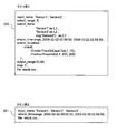
- 8A and 8B are explanatory diagrams illustrating examples of the query 155, the SQL 310, and the CQL 311 in the present embodiment.
- Query example 1 (350) and query example 2 (351) are examples of the query 155.
- Query example 1 (350) is a query 155 when stream data processing is executed.
- Query example 1 (350) extracts the data satisfying the conditions specified in the where_timerrange clause and the where_condition clause for the data of the sensor 100 whose sensor names are “Sensor1” and “Sensor2”, and further extracted. Indicates that data is stored in “result.csv”.
- Query example 2 is a query 155 when stream data processing is not executed.
- Query example 2 (351) extracts the data of the time interval specified in the where_timerrange clause from the data of the sensors 100 whose sensor names are “Sensor1”, “Sensor2”, and “Sensor3”. Is stored in “result.csv”.
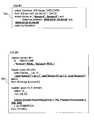
- the SQL example 1 (352) is an example of the SQL 310 generated by the SQL generation unit 301 when the query example 1 (350) is input. A method for generating the SQL 310 will be described later with reference to FIGS. 11A and 11B.
- CQL example 1 (353) is an example of CQL 311 generated by the CQL generation unit 303 when query example 1 (350) is input.
- a method for generating CQL 311 will be described later with reference to FIGS. 12A and 12B.
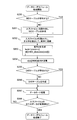
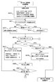
- FIG. 9 is a flowchart for explaining an overview of processing executed by the data search module 157 of this embodiment.
- the data search module 157 receives an input of the query 155 from the data display terminal 106 and starts processing.
- the data search module 157 analyzes the input query 155 (S320). Specifically, the query analysis unit 300 analyzes the input query 155.
- the data search module 157 determines whether or not the input query 155 is a query requesting execution of a feature value search (S321). Specifically, the query analysis unit 300 determines whether the input query 155 includes a meta_search phrase. When the meta_search phrase is included in the input query 155, it is determined that the input query 155 is a query that requests execution of a feature value search. An example of the query 155 including a meta_search phrase will be described later with reference to FIG.
- the data search module 157 When it is determined that the input query 155 is not a query requesting execution of feature value search, the data search module 157 generates an SQL 310 (S322). Specifically, the SQL generation unit 301 generates an SQL 310, and proceeds to S324.
- the data search module 157 When it is determined that the input query 155 is a query requesting execution of feature value search, the data search module 157 generates a SQL 310 for feature value search (S323). Specifically, the feature value search-use SQL generation unit 302 generates a feature value search-use SQL 310, and the process proceeds to S324.
- the data search module 157 determines whether or not to execute stream data processing (S324). Specifically, the query analysis unit 300 determines whether the input query 155 includes a select_items phrase. If the input query 155 includes a select_items phrase, it is determined that stream data processing is to be executed.
- the data search module 157 searches the database 154 based on the SQL 310 generated by the SQL generation unit 301 or the feature value search SQL generation unit 302 (S325). Specifically, the DB search unit 304 searches the database 154 based on the SQL 310 generated by the SQL generation unit 301 or the feature value search SQL generation unit 302, and outputs the searched compressed data to the file A312.
- the data search module 157 decompresses the compressed data stored in the file A 312 and rearranges the decompressed data (S326). Specifically, the data decompression / reordering processing unit 305 decompresses the compressed data stored in the file A, rearranges the decompressed data and outputs it to the file B, and the process proceeds to S332.
- the data search module 157 If it is determined in S324 that the stream data processing is to be executed, the data search module 157 generates the CQL 311 (S327). Specifically, the CQL generation unit 303 generates the CQL 311.
- the data search module 157 searches the database 154 based on the SQL 310 generated by the SQL generation unit 301 or the feature value search SQL generation unit 302 (S328).
- the data search module 157 decompresses the compressed data stored in the file A 312 and rearranges the decompressed data (S329). This process is the same process as S326.
- the data search module 157 executes stream data processing based on the CQL 311 generated by the CQL generation unit 303 (S330). Specifically, the stream data processing unit 306 executes stream data processing based on the CQL 311 generated by the CQL generation unit 303, and outputs the execution result to the file C314.
- the data search module 157 cuts out data to be output from the data stored in the file C314 (S331). Specifically, the cutout processing unit 307 cuts out data to be output from the data stored in the file C314, outputs the cutout data to the file D315, and proceeds to S332.
- the data search module 157 converts the data stored in the file B or the file D315 into output data for display on the data display terminal 106, and outputs the output data to the search result file 156 (S332), and ends the processing.
- FIG. 10A is an explanatory diagram showing a character string cut out by the query analysis unit 300 in the present embodiment.
- the character cutout portion 360 represents a character string cut out from the input query 155.
- the query analysis unit 300 holds a character cutout portion 360 that is a template for specifying a cutout keyword.
- the keyword represents “input_items:”, “select_items”, and the like.
- a character string below the keyword “input_items:” is extracted from the input query 155, and the extracted character string is stored in the variable “$ input”.
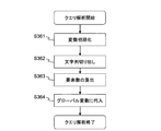
- FIG. 10B is a flowchart illustrating an example of a query analysis process executed by the query analysis unit 300 according to this embodiment.
- the query analysis unit 300 receives an input of the query 155 and starts processing.
- the query analysis unit 300 initializes variables (S361). Specifically, the query analysis unit 300 sets “1” to “$ range”, “$ cond”, and “$ step”, and sets “0” to “$ prev” and “$ post”. In addition, the query analysis unit 300 performs null initialization for “$ input”, “$ select”, “$ start”, “$ end”, “$ file”, and “$ meta”.
- the query analysis unit 300 cuts out a character string from the input query 155 based on the character cutout portion 360, and stores the cutout character string in each variable (S362).
- the query analysis unit 300 cuts out character strings from nine phrases included in the query 155, and converts the cut character strings into variables “$ input”, “$ range”, “$ select”, Stored in “$ start”, “$ end”, “$ cond”, “$ prev”, “$ post”, “$ step”, “$ file”, and “$ meta”.
- the query analysis unit 300 calculates the number of elements included in the variables “$ input” and “$ select” (S363).
- the query analysis unit 300 counts the number of elements separated by “, (comma)” in the character strings included in the variables “$ input” and “$ select”, respectively. Calculate the number. Further, the query analysis unit 300 assigns the number of elements included in the variable “$ input” to the variable “$ inum”, and stores the number of elements included in the variable “$ select” in the variable “$ snum”.
- the query analysis unit 300 outputs each variable as a global variable 309 (S364), and ends the process.
- FIG. 11A is an explanatory diagram showing an SQL template for generating the SQL 310 in the present embodiment.
- the SQL template 370 is a template for generating the SQL 310, and is held by the SQL generation unit 301.
- a time (Datetime) and a sensor name are obtained from a table in which both the SID table 207 and the DAT table 208 are equivalently joined (join operation) with the values shown in the respective ID columns (2072, 2082).
- SID.Name and compressed data (DAT.CDATA) indicate that the SQL is searched based on a predetermined condition.
- the predetermined condition is defined below the where clause. That is, SQL is defined for rearranging data in order of time and acquiring data that matches the specified sensor name and the specified time interval.
- the SQL generation unit 301 uses the global variable 309 to generate the SQL 310 by substituting necessary data into the portions indicated by bold characters and underlined portions of the SQL template 370. Specifically, the SQL generation unit 301 generates “$ db_input”, “$ db_start”, and “$ db_end”, and substitutes the generated data into the SQL template 370.
- FIG. 11B is a flowchart illustrating an example of processing executed by the SQL generation unit 301 of the present embodiment.
- the SQL generation unit 301 generates “$ db_input”, “$ db_start”, and “$ db_end” using the global variable 309 (S371).
- the SQL generation unit 301 generates an SQL 310 (S372) and ends the process.
- the SQL generation unit 301 generates the SQL 310 by substituting the generated “$ db_input”, “$ db_start”, and “$ db_end” into the SQL template 370.
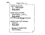
- FIG. 12A is an explanatory diagram showing a CQL template for generating the CQL 311 in the present embodiment.
- the CQL template 380 is a template for generating the CQL 311 and is held by the CQL generation unit 303.
- the CQL generation unit 303 uses the global variable 309 to generate CQL 311 by substituting necessary data for the portions indicated by bold characters and underlined portions of the CQL template 380.
- the CQL generation unit 303 generates “$ cql_input”, “$ cql_select”, “$ range”, “$ cql_label”, and “$ cond”, and substitutes the generated data into the CQL template 380. To do.
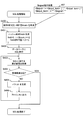
- FIG. 12B is a flowchart illustrating processing executed by the CQL generation unit 303 in the present embodiment.
- the CQL generating unit 303 generates “$ cql_input” using the global variable 309 (S381). Specifically, the following two processes are executed.
- the CQL generation unit 303 executes $ input decomposition processing 385 using “$ input” included in the global variable 309. That is, the CQL generation unit 303 breaks down “$ input” into a plurality of “$ input_item”. This is a process for acquiring individual sensor names from “$ input” including a plurality of sensor names.
- the CQL generation unit 303 executes $ cql_input generation processing 386 using “$ input_item”.
- the CQL generation unit 303 generates “$ cql_input” using “$ input_item” as shown on the right side of the $ cql_input generation processing 386.
- the CQL generation unit 303 generates “$ cql_select” using the global variable 309 (S382). Specifically, the following two processes are executed.
- the CQL generation unit 303 executes $ select decomposition processing 387 using “$ select” included in the global variable 309. This is a process for decomposing elements included in $ select.
- the CQL generation unit 303 acquires “$ func1” or “$ func2” and “$ label” by executing the $ select decomposition process 387.
- the CQL generation unit 303 executes $ cql_select generation processing 388 using “$ func1” or “$ func2” and “$ label” to generate “$ cql_select”.
- $ func1 is an aggregation function, which can describe moving average (avg), variance, maximum value, minimum value, and the like.
- an aggregate function such as avg and a signal name such as “Sensor1” cannot be mixed and handled. Therefore, it is necessary to convert an element including “$ select” into an aggregate function using the last () function. For example, the character string “'Sensor1' as LABEL” is converted to “last ('Sensor1') as LABEL” and an aggregate function.
- the CQL generation unit 303 generates “$ cql_label” using the global variable 309 (S383). Specifically, the CQL generation unit 303 generates “$ cql_label” by executing $ cql_label generation processing 389 using “$ label”.
- the CQL generating unit 303 adds “$ cql_input”, “$ cql_select”, “$ cql_label” generated in S381 to S383, and “$ range” and “$ cond” included in the global variable 309 to the CQL template 380. By substituting, CQL 311 is generated (S384).
- the data search module 157 can simultaneously generate the SQL 310 and the CQL 311 based on the input query 155.
- FIG. 13 is a flowchart for explaining an example of the SQL process executed by the DB search unit of this embodiment.
- the DB search unit 304 generates an array KEY [0] to KEY [$ inum-1] using “$ input” included in the global variable 309 (S400).
- the DB search unit 304 executes the $ signal extraction process 407 using “$ input”. As a result, “$ inum” pieces of “$ signal” are extracted.
- the DB search unit 304 stores each extracted “$ signal” in the array KEY [0] to KEY [$ inum ⁇ 1]. Through the above processing, arrays KEY [0] to KEY [$ inum-1] are generated.
- the DB search unit 304 generates a hash array hash using the generated arrays KEY [0] to KEY [$ inum-1] (S401).
- the DB search unit 304 issues an SQL 310 to the database 154, and the database 154 executes the SQL 310 (S402). As a result, data that matches the condition specified in the issued SQL 310 can be acquired as an execution result.
- the DB search unit 304 extracts one line of data from the acquired execution result, and acquires a time (Datetime) such as date and time, a sensor name (Name), and compressed data (CDATA) from the extracted data ( S403). Note that the extracted data for one row is compressed data for one hour of one sensor.
- a time such as date and time
- a sensor name such as date and time
- CDATA compressed data
- the DB search unit 304 determines whether or not the data for one line extracted from the execution result is empty (S404). That is, it is determined whether or not processing has been completed for all execution results.
- the DB search unit 304 ends the process.
- the DB search unit 304 When it is determined that the data for one line extracted from the execution result is not empty, the DB search unit 304 generates a packet shown in the data structure 1 (340) (S405).
- the DB search unit 304 is obtained from the hash array hash using the time (Datetime) such as date and time included in the retrieved data for one row as the datetime 3401 and the sensor name (Name) as the key.
- the value is stored in idx3402
- the compressed data (CDATA) is stored in zblk 3404
- the size of the compressed data (CDATA) is stored in zlen3403.
- the DB search unit 304 outputs the generated packet to the file A 312 (S406), returns to S403, and executes the processes of S403 to S406.
- FIGS. 14A and 14B are flowcharts for explaining an example of processing executed by the data decompression / sorting processing unit 305 of this embodiment.
- the data decompression / sorting processing unit 305 defines a data [3600] [$ inum] array, a buffer array, and a blk array (S450). In this embodiment, since one piece of compressed data stores 3 hours of data for one sensor 100, a data [3600] [$ inum] array is defined.
- the data decompression / sorting processing unit 305 determines whether “$ snum” included in the global variable 309 is “0” (S451). Thereby, it is determined whether or not the stream data processing is executed. That is, as shown in query example 2 (351) in FIG. 8A, when the select_items phrase is not included in the query 155, “$ snum” is “0”, and therefore it is determined that the stream data processing is not executed.
- the data decompression / sorting processing unit 305 determines the file to output the processing result as the file B313 (S452), and proceeds to S434.
- the data decompressing / sorting processing unit 305 determines the file D315 to be output as a processing result (S453), and proceeds to S434.
- the data decompression / sorting processing unit 305 initializes the data [3600] [$ inum] array and time (S454). Specifically, the data decompression / sorting processing unit 305 initializes data [3600] [$ inum] using a NaN (Not a Number) value, and initializes a variable last indicating time to “0”. Turn into. In the present embodiment, the NaN value is used when initializing the array data. However, any value may be used as long as it does not overlap with a numerical value.
- the data decompression / sorting processing unit 305 takes out one packet shown in the data structure 1 (340) (S455). Specifically, the data decompressing / sorting processing unit 305 takes out the packet from the buffer. If there is no packet in the buffer, the packet is extracted from the file A312. At the time of the first processing, since no packet is stored in the buffer, the packet is extracted from the file A312.
- the data decompressing / sorting processing unit 305 determines whether or not the extracted packet is empty (S456). That is, it is determined whether or not data to be processed is included in the extracted packet.
- the data decompressing / sorting processing unit 305 extracts data from the packet (S457). Specifically, the data decompression / sorting processing unit 305 extracts datetime 3401, idx3402, zlen3403, and zblk3404 from the packet.
- the data decompressing / sorting processing unit 305 determines whether or not the extracted packet is data within the processing time range in order to process the time-series data blocks at the same time in a lump (S458). Specifically, since lastdate holds datetime 3401 of the packet received last time, by comparing datetime 3401 of packet (340) received this time with lastet, the packet is within the processing time range. Whether or not the packet is within the time can be determined.
- the data decompressing / sorting processing unit 305 decompresses the compressed data (S459). Specifically, the data decompressing / sorting processing unit 305 decompresses zblk 3404 included in the extracted packet, and stores the result in blk.
- the data decompressing / sorting processing unit 305 stores the decompressed data in the array data (S460), returns to S455, and executes the processes of S455 to S460. Specifically, the data decompression / sorting processing unit 305 stores blk in the array data. The data decompression / sorting processing unit 305 stores datetime 3401 in the latest.
- the data decompressing / sorting processing unit 305 extracts the packet. The packet is written back to the buffer (S461).
- the data decompressing / sorting processing unit 305 sets the variable i indicating the number of loops to “0”, and repeatedly executes processing 463 and processing 464 for each hour of data in the packet (S462). That is, the process is repeatedly executed until the variable i becomes larger than “3600”.
- the data decompression / sorting processing unit 305 generates an output result (S463). That is, the data decompressing / sorting processing unit 305 generates data as shown in the data structure 2 (341).
- the data decompressing / sorting processing unit 305 outputs the generated output result to the file B313 or the file D315 (S464).
- the data decompression / sorting processing unit 305 determines whether or not the processing of the packet for one hour has been completed (S465). That is, it is determined whether or not the variable i is larger than “3600”. When the variable i is less than “3600”, it is determined that the processing of the packet for one hour has not been completed.
- the data decompression / sorting processing unit 305 returns to S462 and performs the processing of S462 to S466. Execute.
- the data decompression / sorting processing unit 305 processes all the packets stored in the file A 312. It is determined whether or not the process has ended (S466).
- the data decompressing / sorting processing unit 305 returns to S454 and executes the processing of S454 to S466.
- the data decompressing / sorting processing unit 305 ends the processing.
- FIG. 15 is an explanatory diagram showing a configuration example of the stream data processing unit 306 in the present embodiment.
- the stream data processing unit 306 includes an input control unit 500, an input queue 501, a stream data processing engine 502, a user-defined function 503, an output queue 504, and an output control unit 505.
- the input control unit 500 performs input control. Specifically, the input control unit 500 receives data input from the file B 313 and outputs the received data to the input queue 501.
- the input queue 501 stores data input to the input control unit 500.
- the stream data processing engine 502 extracts data from the input queue 501, analyzes the information extracted based on the CQL 311, and outputs the analysis result to the output queue 504.
- the user-defined function 503 stores the definition of the calculation method of the function used in the CQL 311. Details of the user-defined function 503 will be described later with reference to FIG.
- the output queue 504 stores the analysis result input from the stream data processing engine 502.
- the output control unit 505 executes output control. Specifically, the output control unit 505 reads the analysis result from the output queue 504 and outputs the analysis result to the file C.
- data in which the valn 3412 stored in the file B 313 is “$ inum”, that is, data in which values for “$ inum” sensors 100 are stored is transferred from the file B 313 to the stream data processing unit 306. Is input.
- the stream data processing unit 306 outputs the result of executing the processing based on the CQL 311 to the file C314.
- val [0] to val [$ snum ⁇ 1] of the data 3413 are represented by the select_items clause of the query 155.
- the specified processing result is stored, and val [$ snum] in the data 3413 stores the processing result for the condition specified by the where_condition clause of the query 155.
- val [$ snum] when the condition specified in the where_condition clause is met. If the condition specified in the where_condition clause does not match, “0” is stored in val [$ snum].
- the value stored in val [$ snum] is used as a flag for the cutout processing unit 307 described later to determine the cutout range 552 (see FIG. 19).
- the data 3413 of the data stored in the file C 314 contains “$ snum + 1”. ”Values are included.
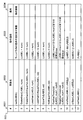
- FIG. 16 is an explanatory diagram illustrating an example of the user-defined function 503 according to the present embodiment.
- the user-defined function 503 includes an identification number 5031, a function name 5032, an operation description 5033, and a remark 5034.
- the identification number 5031 is an identifier for uniquely identifying a function included in the user-defined function 503.
- a function name 5032 is a name of a function included in the CQL 311.
- the operation description 5033 is the operation content of the function corresponding to the function name 5032.
- Remarks 5034 is additional information about the function corresponding to the function name 5032.
- the functions having identification numbers 5031 of “1” to “7” are functions for extracting data in which “LABEL” and “num” satisfy the relationship shown in the operation description 5033.
- the identification numbers 5031 “8” and “9” are functions for extracting data within a predetermined section indicated by the operation description 5033 for “LABEL”.
- the identification numbers 5031 “10” to “12” are functions for executing the logical operation shown in the operation description 5033.
- FIG. 17 is an explanatory diagram illustrating an example of data of a predetermined section extracted by a function included in the user-defined function 503 of the present embodiment.
- PositiveThreshold indicates data of a predetermined section extracted by a function whose identification number 5031 is “8”. As shown in the operation description 5033 of FIG. 17, in PositiveThreshold, data of a section until the value of “LABEL” becomes “num1” or more and the value of “LABEL” becomes smaller than “num2” is extracted.
- NegativeThreshold indicates data of a predetermined section extracted by a function having an identification number 5031 of “9”. As shown in the operation description 5033 of FIG. 17, in Negative Threshold, data of a section until “LABEL” becomes “num1” or less and “LABEL” becomes larger than “num2” is extracted.
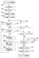
- FIG. 27 is a flowchart for explaining an example of processing executed by the stream data processing unit 306 of the present embodiment.
- the stream data processing unit 306 reads the CQL (S900), and further sets the variable running to “1” (S901).
- the stream data processing unit 306 activates an input control thread and an output control thread (S902, S903).
- the input control unit 500 and the output control unit 505 start processing.
- the processing executed by the input control unit 500 will be described later with reference to FIG.
- the processing executed by the output control unit 505 will be described later with reference to FIG.
- the stream data processing unit 306 determines whether or not there is an empty space in the output queue 504 (S904).
- the stream data processing unit 306 continues to wait until there is space in the output queue 504 (S905).
- the stream data processing unit 306 determines whether data is stored in the input queue 501 (S906).
- the stream data processing unit 306 acquires data from the input queue 501 (S907).
- the stream data processing unit 306 processes the data acquired based on the CQL (S908). Specifically, the stream data processing engine 502 executes CQL.
- the stream data processing unit 306 stores the CQL execution result in the output queue 504 (S909), returns to S904, and executes the same processing.
- the stream data processing unit 306 determines whether or not the variable running is “1” (S911).
- the stream data processing unit 306 enters a waiting state for processing (S910), returns to S906, and executes the same processing.
- the stream data processing unit 306 determines whether data is stored in the output queue 504 (S912).
- the stream data processing unit 306 continues to wait until data is stored in the output queue 504 (S913).
- the stream data processing unit 306 stops the input control thread and the output control thread (S914, S915), and ends the process. Thereby, the processes of the input control unit 500 and the output control unit 505 are completed.
- FIG. 28 is a flowchart illustrating an example of processing executed by the input control unit 500 of this embodiment.
- the input control unit 500 determines whether or not the input queue 501 is empty (S922).
- the input control unit 500 continues to wait until there is space in the input queue 501 (S921).
- the input control unit 500 determines whether data exists in the file B 313 (S923).
- the input control unit 500 sets the variable running to “0” (S926), and ends the process (S927).
- the input control unit 500 acquires data from the file B313 (S924), stores the acquired data in the input queue 501 (S925), returns to S922, and performs similar processing. Execute.
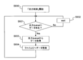
- FIG. 29 is a flowchart illustrating an example of processing executed by the output control unit 505 of the present embodiment.
- the output control unit 505 determines whether data exists in the output queue 504 (S931).
- the output control unit 505 continues to wait until data is stored in the output queue 504 (S932).
- the output control unit 505 acquires data from the output queue 504 (S933), and stores the acquired data in the file C314 (S934).
- the output control unit 505 then returns to S931 and executes the same processing.
- FIG. 18A is a flowchart for explaining an example of processing executed by the cutout processing unit 307 of this embodiment.
- the cutout processing unit 307 starts processing after the processing of the stream data processing unit 306 is completed.
- the cut-out processing unit 307 executes initialization of the variable prev_cnt, the variable post_cnt, and the variable latest, generation and initialization of the FIFO buffer, and definition and initialization of the data buffer (S570).
- the cutout processing unit 307 initializes the variable prev_cnt and the variable post_cnt to “0”. In addition, the cutout processing unit 307 initializes the variable “latest” as “$ start ⁇ $ prev ⁇ 1”. In addition, the cutout processing unit 307 generates a ($ prev + 1) stage FIFO buffer, and initializes the generated FIFO buffer to “0”. Note that the variable prev_cnt and the variable post_cnt are variables used in a clipping process described later.
- the cutout processing unit 307 reads one piece of data from the file C314 and stores it in data (S571). Note that the file C 314 stores a plurality of data structure 2 (341) data corresponding to one line as a result of the operation of the select_items phrase.
- the cutout processing unit 307 determines whether or not the data read from the file C314 is terminal data stored in the file C314 (S572). For example, this can be done by determining whether the datetime 3411 of the read data is the same as “$ end” included in the global variable 309.
- the cutout processing unit 307 sets the variable diff to “datetime ⁇ , using the datetime 3411 and the variable“ latest ”included in the data. “latest” is set (S573), and the process proceeds to S575.
- the cutout processing unit 307 sets the variable diff to “$ prev + 1” (S574), and proceeds to S575. .
- the cutout processing unit 307 substitutes the value set in the variable diff for the variable i, and repeatedly executes the process until the variable i becomes smaller than “0” (S575).
- the cutout processing unit 307 determines whether or not the variable i is “1” (S576).
- the cutout processing unit 307 If it is determined that the variable i is not “1”, the cutout processing unit 307 generates dummy data (hereinafter also referred to as insertion data) to be inserted into the FIFO buffer (S577), and the process proceeds to S580.
- dummy data hereinafter also referred to as insertion data
- insertion data as shown in data structure 2 (341) is generated.
- “latest + 1” is set in the datetime 3411 of the insertion data
- “$ snum + 1” is set in the valn 3412.
- a value (NaN) indicating empty data is set in val [0] to [$ snum-1] of the data 3413 of the insertion data, and “0” is set in val [$ snum].
- the cut-out processing unit 307 determines whether the data (indate) read from the file C314 is the terminal data stored in the file C314. (S578). For this determination, the same method as in S572 is used.
- the cutout processing unit 307 ends the process.
- the cutout processing unit 307 When it is determined that the data read from the file C314 is not the terminal data stored in the file C314, the cutout processing unit 307 generates input data (S579), and proceeds to S580. Specifically, the cutout processing unit 307 sets the value stored in the data to the setting of input data.
- the cutout processing unit 307 executes cutout processing using the input data (S580). Details of the cut-out process will be described later with reference to FIG. 18B.
- the cutout processing unit 307 determines whether or not to repeatedly execute the process (S581, S575). That is, the cutout processing unit 307 determines whether or not to continue the for statement loop in S575. Specifically, the variable i is decremented and it is determined whether or not “i> 0”. When the determination result is true, it is determined that the process is repeatedly executed.
- the cutout processing unit 307 returns to S575 and executes the same process (S575 to S581).
- the cutout processing unit 307 returns to S571 and executes the same process (S571 to S581).
- FIG. 18B is a flowchart for explaining the details of the cut-out process of the present embodiment.
- the cutout processing unit 307 sets the datetime of the insertion data to the variable latest (S582).
- the cut-out processing unit 307 inputs one insertion data to the FIFO buffer and outputs one data from the FIFO buffer (S583).
- data output from the FIFO buffer is also referred to as output data.
- the cutout processing unit 307 determines whether or not val [$ snum] of the input insertion data is “1” (S584).
- the cut-out processing unit 307 adds “1” to the value of the variable prev_cnt (S585), and proceeds to S586.
- the cutout processing unit 307 determines whether or not val [$ snum] of the output data that is output is “1” (S586).
- the cut-out processing unit 307 subtracts “1” from the value of the variable prev_cnt (S587), and proceeds to S588.
- the cutout processing unit 307 executes a cutout condition determination process based on the variable prev_cnt, the variable post_cnt, and the value of val [$ snum] of the input insertion data (S588). Specifically, the following determination process is executed.
- the cutout processing unit 307 executes three determination processes.
- the cutout processing unit 307 determines whether or not the value of the variable prev_cnt is greater than “0”. Hereinafter, this determination is referred to as a cutout condition (1).
- the cutout processing unit 307 determines whether or not the value of val [$ snum] of the output data that is output is “1”. Hereinafter, this determination is referred to as a cutout condition (2).
- the cutout processing unit 307 determines whether or not the value of the variable post_cnt is greater than “0”. Hereinafter, this determination is referred to as a cutout condition (3).
- the cutout processing unit 307 determines whether or not at least one of the cutout conditions (1), (2), and (3) is satisfied based on the execution result of the cutout condition determination process (S589).
- the cutout processing unit 307 finishes the cutout processing S580 and proceeds to S581.
- the cutout processing unit 307 selects the cutout conditions (1) or (2) based on the execution result of the cutout condition determination process. It is determined whether or not at least one of the above is satisfied (S590).
- the cutout processing unit 307 sets the value of “$ post” to the variable post_cnt (S591), and proceeds to S593.
- the cutout processing unit 307 subtracts “1” from the variable post_cnt (S592), and proceeds to S593.
- the cutout processing unit 307 outputs the fout data to the file D315 (S593), finishes the cutout processing S580, and proceeds to S581.
- the file D315 stores an output result to which an offset before and after including data that satisfies the condition specified by the where_condition clause of the query 155 is added.
- the cutout processing unit 307 satisfies a flag indicating that the cutout condition (1) is satisfied, a flag indicating that the cutout condition (2) is satisfied, and satisfying the cutout condition (3).
- a flag is assigned to each inserted data. Further, the cutout processing unit 307 determines each cutout condition based on the flag.
- FIG. 19 is an explanatory diagram illustrating an example of an output result output by the cutout processing unit 307 of the present embodiment.
- the cutout processing unit 307 When query example 3 (550) is input, the cutout processing unit 307 outputs a result as shown in the output result 551.
- LABEL is “L1” and the value of Sensor1 is “100” or more
- the condition establishment range 554 the cutout range 552 including the front offset 553 and the rear offset 555, or the condition satisfaction range 554,
- a cutout range 552 including a front offset 553, a rear offset 555, and a combined offset 556 is output.
- the combined offset 556 is obtained by combining portions where the front offset 553 and the rear offset 555 overlap as one offset.
- the output result is generated based on the flag assigned in S589 of FIG. That is, the insertion data to which any one of the clipping conditions (1) to (3) is attached is output as the clipping range 552. Specifically, it is as follows.
- the insertion data to which the flag of the cutout condition (2) is added is output as data included in the condition establishment range 554 in the cutout range 552.
- the insertion data to which the flag of the cutout condition (1) is assigned is output as data included in the forward offset 553 in the cutout range 552.
- the insertion data to which the flag of the cutout condition (3) is assigned is output as data included in the rear offset 555 in the cutout range 552.
- the cutout processing unit 307 cuts out insertion data that matches the respective cutout conditions (1) to (3), rearranges the cutout data in time order (sorts), and outputs the data.
- the insertion data to which two or more flags of any one of the extraction conditions (1) to (3) are added is output as the extraction range 552 including the combined offset 556.
- FIG. 20 is a flowchart illustrating an example of processing executed by the data output unit 308 according to the embodiment of this invention.
- the data output unit 308 defines a tmp buffer (S605).
- the data output unit 308 reads data from the file D315 and stores the read data in tmp (S600).
- the data to be read is data as shown in the data structure 2 (341) corresponding to one line as a result of the operation of the select_items clause.
- the data output unit 308 refers to the datetime 3411 of the read data and executes a search result extraction process (S601). Specifically, the following two processes are executed.
- the data output unit 308 determines whether or not the value stored in the datetime 3411 is included in the time range specified in the where_timerange clause of the query 155. That is, it is determined whether or not the value stored in the datetime 3411 is not less than “$ start” and not more than “$ end”. Hereinafter, this determination is referred to as output condition (1).
- the reason why the process of determining whether or not the output condition (1) is satisfied is that the data in the range searched by the SQL 310 is the data in a range wider than the time range specified in the query 155. It is. That is, as described with reference to FIG. 11B, “$ db_start” (see FIG. 11B) used when generating the SQL 310 also processes data at a time before “$ start”.
- the data output unit 308 performs a thinning process. Specifically, it is determined whether or not the value stored in the datetime 3411 is a value specified in the step clause of the query 155, that is, the remainder obtained by dividing “$ step” is “0”. Hereinafter, this determination is referred to as an output condition (2). In the example shown in Query Example 1 (350), data every 5 seconds is output according to the output condition (2).
- the data output unit 308 determines whether or not the output condition (1) and the output condition (2) are satisfied based on the result of the search result extraction process in S601 (S602).
- the data output unit 308 proceeds to S604. That is, the data is not output.
- the data output unit 308 executes a search result generation process (S603). Specifically, the data output unit 308 converts the data stored in the tmp into a CSV format as shown in the data structure 3 (342) and outputs it to the search result file 156.
- the data output unit 308 determines whether or not processing has been completed for all data stored in the file D315 (S604).
- compressed data compressed in an hour unit is searched, and in the data decompression / sorting process, the compressed data compressed in an hour unit is decompressed to generate data in one second unit. Thereafter, in the stream data process, the cutout process, and the output data generation process, the process is performed on the data in units of one second. In the output data generation process, data is processed in units of one second, but data is output in units specified by $ step.
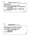
- FIG. 21 is an explanatory diagram showing an example of the query 155 and the SQL 310 when the feature value search process is executed in the present embodiment.
- the feature value search SQL generation unit 302 When the data search module 157 receives a query 155 including a meta_search phrase, the feature value search SQL generation unit 302 generates an SQL example 4-1 (701) as shown in FIG. After 1 (701) is executed, SQL example 4-2 (702) is generated.
- SQL example 4-1 (701) is an SQL for time cut-out, and is an SQL for extracting the time (Datetime) of data matching the feature value.
- SQL example 4-2 (702) is an SQL for feature value search, and is an SQL for executing the search of the database 154 within the range of Datetime extracted by SQL example 4-1 (701).
- the SQL example 4-2 (702) is the same SQL 310 as the SQL example 1 (352), but compared to the SQL example 1 (352), the SQL example 4-2 (702) is the SQL example 4-1 ( Since the search range is limited by the execution of 701), the search processing time can be greatly reduced.
- the user does not necessarily need to specify the meta_search phrase.
- threshold determination time-series data that exceeds a certain threshold is included in a packet set whose maximum value exceeds the threshold.
- time-series data that falls below a certain threshold is included in a packet set whose minimum value falls below the threshold.
- a meta_search phrase can be automatically generated. Specifically, in the query example 4 in FIG. 21, when a greeterthan phrase and a threshold are specified in the where_condition phrase, MaxVal> threshold is automatically given as a phrase in which the maximum value exceeds the threshold in the meta_search phrase.
- MinVal ⁇ threshold is automatically given as a phrase in which the maximum value exceeds the threshold in the meta_search phrase.
- Such query conversion rules may be registered in advance in the system, or may be registered later by the user.
- FIG. 22 is an explanatory diagram showing an SQL template for generating an SQL 310 for feature value search in the present embodiment.
- the feature value search SQL generating unit 302 holds a time cut-out SQL template 710 and a feature value search SQL template 711.
- the time cut-out SQL template 710 is a template for generating the SQL 310 when executing the feature value search, and is an SQL for extracting the time of the compressed data including the data matching the feature value.
- the time (Datetime) is searched based on a predetermined condition from a table obtained by combining the SID table 207 and the DAT table 208 in which the ID column 2072 and the ID column 2082 are the same. .
- the predetermined condition is defined below the where clause. That is, it is defined that data is rearranged in order of time, and data that matches a specified sensor name, a specified feature value, and a specified time section is defined.
- the feature value search SQL template 711 is a template for generating the SQL 310 when executing the feature value search.
- the compressed data SQL for searching In the time range extracted by the SQL generated using the time cut-out SQL template 710, the compressed data SQL for searching.
- the time (Datetime), the sensor name (SID.Name), and the compressed data (DAT) are obtained from a combination of the SID table 207 and the DAT table 208 in which the ID column 2072 and the ID column 2082 are the same.
- .CDATA indicates that the SQL is to be searched based on a predetermined condition.
- the predetermined condition is defined below the where clause. That is, it is defined that data is rearranged in order of time, and data that matches a specified sensor name and a specified time section is acquired.
- FIG. 23 is a flowchart illustrating an example of processing executed by the feature value search SQL generation unit 302 of the present embodiment.
- the feature value search SQL generating unit 302 generates “$ meta_signal” and “$ meta_cond” using the global variable 309 (S720). Specifically, the feature value search SQL generating unit 302 executes $ meta decomposition processing 730 using “$ meta” included in the global variable 309. That is, the feature value search SQL generating unit 302 breaks down “$ meta” into “$ meta_signal” and “$ meta_cond”.
- the feature value search SQL generating unit 302 defines a work variable $ dt_tmp (S7201).
- the feature value search SQL generator 302 generates a time cut-out SQL (S721).
- the feature value search-use SQL generating unit 302 generates “time-cutting SQL” by substituting “$ meta_signal”, “$ meta_cond”, “$ meta_start”, and “$ meta_end” into the time-cutting SQL template 710. To do.
- the feature value search SQL generation unit 302 issues a time cut-out SQL to the database 154 (S722).
- the feature value search SQL generation unit 302 acquires the execution result from the database 154 that has executed the time cut-out SQL, and stores it in $ dt_tmp (S723). Specifically, time data that matches the conditions specified in the time cut-out SQL is acquired as an execution result and stored in $ dt_tmp.
- the feature value search SQL generating unit 302 determines whether or not the data for one line stored in $ dt_tmp is null (S724). That is, it is determined whether or not processing has been completed for all execution results.
- the feature value search SQL generation unit 302 stores the start time of the time-series data block in which the sensor data at time $ dt_tmp is stored, Then, end times, that is, “$ db_start” and “$ db_end” are calculated (S726).
- the reason for adding “3599” is that in this embodiment, data is compressed and stored in the database in units of one hour.
- the feature value search SQL generating unit 302 generates “$ db_dtset” using “$ db_start” and “$ db_end” calculated in S726 (S727), and returns to S723 to execute the same processing. Specifically, the feature value search SQL generation unit 302 executes $ db_dtset generation processing using “$ db_start” and “$ db_end”.
- FIG. 24 is a flowchart illustrating a case where the processes executed by the data search module 157 are executed in parallel in the present embodiment.
- the CPU 121 includes a plurality of cores, and as shown in FIG. 10, the processes 1 to 4 can be executed simultaneously with the execution of the DB search 3204.
- S3200 to S3202 are the same processes as S320 to S323 and S327 of FIG.
- the data search module 157 activates processes 1 to 4 (S3203), and executes each process in each process (S3204 to S3208).
- data decompression / reordering processing is executed in process 1
- stream data processing is executed in process 2
- clipping processing is executed in process 3
- output data generation processing is executed in process 4. .
- the amount of data stored in the database can be reduced by storing the compressed data obtained by compressing the time series data in a predetermined time unit in the database. Also, by accepting one query, SQL for searching for compressed data and CQL for processing the decompressed data can be generated. Furthermore, by outputting a cutout range that combines the range that satisfies the conditions specified in CQL and the sections before and after the range, not only the location where the abnormality occurred, but also the time series data before and after the occurrence of the abnormality It is possible to output, and it becomes easy to trace for identifying an abnormal part and an abnormal cause.
- the present invention can be applied to preventive maintenance of facilities in factories and plants that handle enormous amounts of data.
Landscapes
- Engineering & Computer Science (AREA)
- Theoretical Computer Science (AREA)
- Physics & Mathematics (AREA)
- General Physics & Mathematics (AREA)
- Databases & Information Systems (AREA)
- General Engineering & Computer Science (AREA)
- Data Mining & Analysis (AREA)
- Computational Linguistics (AREA)
- Fuzzy Systems (AREA)
- Mathematical Physics (AREA)
- Probability & Statistics with Applications (AREA)
- Software Systems (AREA)
- Automation & Control Theory (AREA)
- Information Retrieval, Db Structures And Fs Structures Therefor (AREA)
Abstract
Description
Claims (28)
- プロセッサと、前記プロセッサに接続されるメモリとを備え、データベースを管理する計算機におけるデータベース管理方法であって、
前記データベースは、所定の条件に基づいて圧縮された複数の圧縮データを格納し、
前記方法は、
前記計算機に接続されるクライアント計算機から前記データベースへのクエリを受け付けた場合に、前記計算機が、前記受け付けたクエリを解析する第1のステップと、
前記計算機が、前記受け付けたクエリの解析結果に基づいて、前記データベースから一つ以上の前記圧縮データを検索するための第1の問い合わせを生成する第2のステップと、
前記計算機が、前記受け付けたクエリの解析結果に基づいて、前記第1の問い合わせの応答結果である前記一つ以上の圧縮データから取得される複数の時系列データに対する検索を実行するための第2の問い合わせを生成する第3のステップと、
前記計算機が、前記データベースに前記第1の問い合わせを発行して、前記データベースから前記第1の問い合わせの応答結果として一つ以上の前記圧縮データを取得する第4のステップと、
前記計算機が、前記第1の問い合わせに対する応答結果として取得された一つ以上の圧縮データを解凍することによって前記複数の時系列データを取得する第5のステップと、
前記計算機が、前記取得された複数の時系列データに対して前記第2の問い合わせを実行する第6のステップと、
前記計算機が、前記第2の問い合わせに対する応答結果に基づいて、前記取得された複数の時系列データから所定のデータを抽出する第7のステップと、
前記計算機が、前記第7のステップにおいて抽出された所定のデータから前記クライアント計算機に出力するためのデータを抽出し、出力結果を生成する第8のステップと、を含むことを特徴とするデータベース管理方法。 - 前記圧縮データは、前記複数の時系列データが所定の時間単位に圧縮された圧縮データであり、
前記第2の問い合わせは、前記複数の時系列データから所定の閾値の条件を満たす第1のデータ範囲を検索するための問い合わせであり、
前記第6のステップは、前記計算機が、前記第1のデータ範囲に含まれる前記時系列データにフラグを付与し、
前記第7のステップは、前記計算機が、前記時系列データに付与されたフラグに基づいて、前記第1のデータ範囲を含む第2のデータ範囲を抽出することを特徴とする請求項1に記載のデータベース管理方法。 - 前記第2のデータ範囲は、
前記第1のデータ範囲の時刻が最も過去の前記時系列データから第1の時間さかのぼった範囲に含まれる前記時系列データを抽出する第3のデータ範囲と、
前記第1のデータ範囲の時刻が最新の前記時系列データから第2の時間進んだ範囲に含まれる前記時系列データを抽出する第4のデータ範囲と、を含むことを特徴とする請求項2に記載のデータベース管理方法。 - 前記第8のステップは、前記第2のデータ範囲に含まれる時系列データのうち、所定の時間間隔の前記時系列データを抽出するステップを含むことを特徴とする請求項2に記載のデータベース管理方法。
- 前記データベースは、検索キーとなる特徴情報を付加した前記圧縮データを格納し、
前記第1の問い合わせは、
前記特徴情報を含み、
当該第1の問い合わせに含まれる特徴情報に一致する前記特徴情報が付加された前記圧縮データを検索するための問い合わせであることを特徴とする請求項1に記載のデータベース管理方法。 - 前記特徴情報は、前記圧縮データが圧縮される前の複数の時系列データにおける最大値、最小値、平均値、分散値又は周波数スペクトル上の特定点の少なくともいずれかであることを特徴とする請求項5に記載のデータベース管理方法。
- 前記第1の問い合わせは、前記データベースから前記圧縮データを検索するためのSQLであり、
前記第2の問い合わせは、前記時系列データから所定のデータを抽出するためのCQLであることを特徴とする請求項1に記載のデータベース管理方法。 - プロセッサと、前記プロセッサに接続されるメモリとを備え、データベースを管理する計算機であって、
前記データベースは、所定の条件に基づいて圧縮された複数の圧縮データを格納し、
前記計算機は、
前記計算機に接続されるクライアント計算機から前記データベースへのクエリを受け付けた場合に、前記受け付けたクエリを解析し、
前記受け付けたクエリの解析結果に基づいて、前記データベースから一つ以上の前記圧縮データを検索するための第1の問い合わせを生成し、
前記受け付けたクエリの解析結果に基づいて、前記第1の問い合わせの応答結果である前記一つ以上の圧縮データから取得される複数の時系列データに対する検索を実行するための第2の問い合わせを生成し、
前記データベースに前記第1の問い合わせを発行して、前記データベースから前記第1の問い合わせの応答結果として一つ以上の前記圧縮データを取得し、
前記第1の問い合わせに対する応答結果として取得された一つ以上の圧縮データを解凍することによって前記複数の時系列データを取得し、
前記取得された複数の時系列データに対して前記第2の問い合わせを実行し、
前記第2の問い合わせに対する応答結果に基づいて、前記取得された複数の時系列データから所定のデータを抽出し、
前記抽出された所定のデータから前記クライアント計算機に出力するためのデータを抽出し、出力結果を生成することを特徴とする計算機。 - 前記圧縮データは、前記複数の時系列データが所定の時間単位に圧縮された圧縮データであり、
前記第2の問い合わせは、前記複数の時系列データから所定の閾値の条件を満たす第1のデータ範囲を検索するための問い合わせであり、
前記計算機は、
前記取得された複数の時系列データに対して前記第2の問い合わせを実行する場合に、前記第1のデータ範囲に含まれる前記時系列データにフラグを付与し、
前記第2の問い合わせに対する応答結果に基づいて、前記取得された複数の時系列データから所定のデータを抽出する場合に、前記時系列データに付与されたフラグに基づいて、前記第1のデータ範囲を含む第2のデータ範囲を抽出することを特徴とする請求項8に記載の計算機。 - 前記第2のデータ範囲は、
前記第1のデータ範囲の時刻が最も過去の前記時系列データから第1の時間さかのぼった範囲に含まれる前記時系列データを抽出する第3のデータ範囲と、
前記第1のデータ範囲の時刻が最新の前記時系列データから第2の時間進んだ範囲に含まれる前記時系列データを抽出する第4のデータ範囲と、を含むことを特徴とする請求項9に記載の計算機。 - 前記データベースは、検索キーとなる特徴情報を付加した前記圧縮データを格納し、
前記第1の問い合わせは、
前記特徴情報を含み、
当該第1の問い合わせに含まれる特徴情報に一致する前記特徴情報が付加された前記圧縮データを検索するための問い合わせであることを特徴とする請求項8に記載の計算機。 - 前記特徴情報は、前記圧縮データが圧縮される前の複数の時系列データにおける最大値、最小値、平均値、又は分散値の少なくともいずれかであることを特徴とする請求項11に記載の計算機。
- 前記第1の問い合わせは、前記データベースから前記圧縮データを検索するためのSQLであり、
前記第2の問い合わせは、前記時系列データから所定のデータを抽出するためのCQLであることを特徴とする請求項8に記載の計算機。 - 観測対象の物理量を測定するセンサと、前記センサが測定した前記物理量を時系列データとして収集する計算機と、前記第1の計算機から前記時系列データをデータベースに格納する管理サーバと、を備えるセンサノードシステムにおいて、
前記計算機は、第1のプロセッサと、前記第1のプロセッサに接続される第1のメモリとを備え、
前記管理サーバは、第2のプロセッサと、前記第2のプロセッサに接続される第2のメモリとを備え、
前記計算機と前記管理サーバとはネットワークを介して接続され、
前記データベースは、所定の条件に基づいて前記時系列データが圧縮された複数の圧縮データを格納し、
前記管理サーバは、
前記管理サーバに前記ネットワークを介して接続されるクライアント計算機から前記データベースへのクエリを受け付けた場合に、前記受け付けたクエリを解析し、
前記受け付けたクエリの解析結果に基づいて、前記データベースから一つ以上の前記圧縮データを検索するための第1の問い合わせを生成し、
前記受け付けたクエリの解析結果に基づいて、前記第1の問い合わせの応答結果である前記一つ以上の圧縮データから取得される複数の前記時系列データに対する検索を実行するための第2の問い合わせを生成し、
前記データベースに前記第1の問い合わせを発行して、前記データベースから前記第1の問い合わせの応答結果として一つ以上の前記圧縮データを取得し、
前記第1の問い合わせに対する応答結果として取得された一つ以上の圧縮データを解凍することによって前記複数の時系列データを取得し、
前記取得された複数の時系列データに対して前記第2の問い合わせを実行し、
前記第2の問い合わせに対する応答結果に基づいて、前記取得された複数の時系列データから所定のデータを抽出し、
前記抽出された所定のデータから前記クライアント計算機に出力するためのデータを抽出し、出力結果を生成することを特徴とするセンサネットワークシステム。 - 前記圧縮データは、前記複数の時系列データが所定の時間単位に圧縮された圧縮データであり、
前記第2の問い合わせは、前記複数の時系列データから所定の閾値の条件を満たす第1のデータ範囲を検索するための問い合わせであり、
前記管理サーバは、
前記取得された複数の時系列データに対して前記第2の問い合わせを実行する場合に、前記第1のデータ範囲に含まれる前記時系列データにフラグを付与し、
前記第2の問い合わせに対する応答結果に基づいて、前記取得された複数の時系列データから所定のデータを抽出する場合に、前記時系列データに付与されたフラグに基づいて、前記第1のデータ範囲を含む第2のデータ範囲を抽出することを特徴とする請求項14に記載のセンサネットワークシステム。 - 前記第2のデータ範囲は、
前記第1のデータ範囲の時刻が最も過去の前記時系列データから第1の時間さかのぼった範囲に含まれる前記時系列データを抽出する第3のデータ範囲と、
前記第1のデータ範囲の時刻が最新の前記時系列データから第2の時間進んだ範囲に含まれる前記時系列データを抽出する第4のデータ範囲と、を含むことを特徴とする請求項15に記載のセンサネットワークシステム。 - 前記データベースは、検索キーとなる特徴情報を付加した前記圧縮データを格納し、
前記第1の問い合わせは、
前記特徴情報を含み、
当該第1の問い合わせに含まれる特徴情報に一致する前記特徴情報が付加された前記圧縮データを検索するための問い合わせであることを特徴とする請求項14に記載のセンサネットワークシステム。 - 前記特徴情報は、前記圧縮データが圧縮される前の複数の時系列データにおける最大値、最小値、平均値、又は分散値の少なくともいずれかであることを特徴とする請求項17に記載のセンサネットワークシステム。
- 前記第1の問い合わせは、前記データベースから前記圧縮データを検索するためのSQLであり、
前記第2の問い合わせは、前記時系列データから所定のデータを抽出するためのCQLであることを特徴とする請求項14に記載のセンサネットワークシステム。 - プロセッサと、前記プロセッサに接続されるメモリとを備え、データベースを管理する計算機におけるデータベース検索プログラムであって、
前記データベースは、所定の条件に基づいて圧縮された複数の圧縮データを格納し、
前記プログラムは、
前記計算機に接続されるクライアント計算機から前記データベースへのクエリを受け付けた場合に、前記受け付けたクエリを解析する手順と、
前記受け付けたクエリの解析結果に基づいて、前記データベースから一つ以上の前記圧縮データを検索するための第1の問い合わせを生成する手順と、
前記受け付けたクエリの解析結果に基づいて、前記第1の問い合わせの応答結果である前記一つ以上の圧縮データから取得される複数の時系列データに対する検索を実行するための第2の問い合わせを生成する手順と、
前記データベースに前記第1の問い合わせを発行して、前記データベースから前記第1の問い合わせの応答結果として一つ以上の前記圧縮データを取得する手順と、
前記第1の問い合わせに対する応答結果として取得された前記一つ以上の圧縮データを解凍することによって前記複数の時系列データを取得する手順と、
前記取得された複数の時系列データに対して前記第2の問い合わせを実行する手順と、
前記第2の問い合わせに対する応答結果に基づいて、前記取得された複数の時系列データから所定のデータを抽出する手順と、
前記抽出された所定のデータから前記クライアント計算機に出力するためのデータを抽出し、出力結果を生成する手順と、を前記計算機に実行させることを特徴とするデータベース検索プログラム。 - 時系列データに対して時系列処理を行うことで特徴量を生成し、時系列を時系列ブロックに分割し、該特徴量を検索キーとなるメタ情報として時系列ブロックとともに時系列蓄積装置に格納する時系列データ格納手段と、
ユーザからの問い合わせに応じて該特徴量を検索キーに時系列ブロックを検索する第一の問合せと、時系列ブロック内の時系列を検索する第二の問い合わせを生成する手段と、
第一の問い合わせにより該時系列ブロックを検索する第一の検索手段と、
得られた時系列ブロックを逐次第二の問い合わせに基づき時系列処理を行って時系列を検索し、問合せ結果を出力する第二の検索手段と、を有することを特徴とする時系列データ管理方法。 - 利用者の最も利用する検索期間を統計処理により生成することにより前記時系列ブロックの分割範囲を得る請求項21に記載の時系列データ管理方法。
- 時系列の特徴変化が起こる最小期間を統計処理により生成することにより前記時系列ブロックの分割範囲を得る請求項21に記載の時系列データ管理方法。
- 前記時系列データ格納手段では時系列ブロックを圧縮する手段を、前記第二の検索手段では圧縮された時系列ブロックを展開する手段を備えることを特徴とする請求項21に記載の時系列データ管理方法。
- 前記ユーザからの問い合わせが閾値超過ないし未満判定の場合、前記第一の検索手段で最大値ないし最小値との超過判定ないし未満判定で時系列ブロックを絞り込むことを特徴とする請求項21に記載の時系列データ管理方法。
- 時系列データに対して時系列処理を行うことで特徴量を生成し、時系列を時系列ブロックに分割し、該特徴量を検索キーとなるメタ情報として時系列ブロックとともに時系列蓄積装置に格納する時系列データ格納手段と、
ユーザからの問い合わせに応じて該特徴量を検索キーに時系列ブロックを検索する第一の問合せと、時系列ブロック内の時系列を検索する第二の問い合わせを生成する手段と、
第一の問い合わせにより該時系列ブロックを検索する第一の検索手段と、
得られた時系列ブロックを逐次第二の問い合わせに基づき時系列処理を行って時系列を検索し、問合せ結果を出力する第二の検索手段と、を有することを特徴とする計算機。 - リアルタイムに到来する時系列データを所定期間メモリ上に蓄積し、時系列解析を行うことで前記特徴量を生成するストリームデータ処理エンジンを備えることを特徴とする請求項26に記載の計算機。
- 前記第二の検索手段において、移動平均、区間抽出、間引き処理の少なくともいずれかを行うストリームデータ処理エンジンを備えることを特徴とする請求項26に記載の計算機。
Priority Applications (3)
| Application Number | Priority Date | Filing Date | Title |
|---|---|---|---|
| EP10849477.4A EP2557504A4 (en) | 2010-04-09 | 2010-07-22 | DATABASE MANAGEMENT, COMPUTER, SENSOR NETWORK, AND DATABASE SEARCH PROGRAM |
| CN201080065327.7A CN102792282B (zh) | 2010-04-09 | 2010-07-22 | 数据库管理方法、计算机、传感器网络系统 |
| US13/583,108 US8898189B2 (en) | 2010-04-09 | 2010-07-22 | Database management method, computer, sensor network system and time-series data management method |
Applications Claiming Priority (2)
| Application Number | Priority Date | Filing Date | Title |
|---|---|---|---|
| JP2010090491A JP5423553B2 (ja) | 2010-04-09 | 2010-04-09 | データベース管理方法、計算機、センサネットワークシステム及びデータベース検索プログラム |
| JP2010-090491 | 2010-04-09 |
Publications (1)
| Publication Number | Publication Date |
|---|---|
| WO2011125237A1 true WO2011125237A1 (ja) | 2011-10-13 |
Family
ID=44762214
Family Applications (1)
| Application Number | Title | Priority Date | Filing Date |
|---|---|---|---|
| PCT/JP2010/062343 Ceased WO2011125237A1 (ja) | 2010-04-09 | 2010-07-22 | データベース管理方法、計算機、センサネットワークシステム及びデータベース検索プログラム |
Country Status (5)
| Country | Link |
|---|---|
| US (1) | US8898189B2 (ja) |
| EP (1) | EP2557504A4 (ja) |
| JP (1) | JP5423553B2 (ja) |
| CN (1) | CN102792282B (ja) |
| WO (1) | WO2011125237A1 (ja) |
Cited By (1)
| Publication number | Priority date | Publication date | Assignee | Title |
|---|---|---|---|---|
| JP6085359B1 (ja) * | 2015-12-17 | 2017-02-22 | 西日本電信電話株式会社 | データベースシステム及びデータ処理方法 |
Families Citing this family (54)
| Publication number | Priority date | Publication date | Assignee | Title |
|---|---|---|---|---|
| KR101380936B1 (ko) * | 2006-10-05 | 2014-04-10 | 스플렁크 인코퍼레이티드 | 시계열 검색 엔진 |
| US9298854B2 (en) * | 2010-05-14 | 2016-03-29 | Hitachi, Ltd. | Time-series data management device, system, method, and program |
| JP5510760B2 (ja) | 2010-05-17 | 2014-06-04 | 株式会社日立製作所 | 計算機システム、及び、規則生成方法 |
| JP5890963B2 (ja) * | 2011-03-17 | 2016-03-22 | 富士通株式会社 | データ保存プログラム及びデータ保存方法 |
| JP5843636B2 (ja) * | 2012-02-01 | 2016-01-13 | 三菱電機株式会社 | 時系列データ照会装置、時系列データ照会方法及び時系列データ照会プログラム |
| US10311513B2 (en) * | 2012-03-14 | 2019-06-04 | Nasdaq Technology Ab | Method and system for facilitating access to recorded data |
| JPWO2013137067A1 (ja) * | 2012-03-15 | 2015-08-03 | 日本電気株式会社 | 演算装置、演算方法及び演算プログラム |
| US9563663B2 (en) | 2012-09-28 | 2017-02-07 | Oracle International Corporation | Fast path evaluation of Boolean predicates |
| JP6041431B2 (ja) * | 2012-10-16 | 2016-12-07 | 株式会社日立製作所 | ストリームデータ処理方法、ストリームデータ処理装置及びプログラム |
| US9069824B2 (en) * | 2012-11-15 | 2015-06-30 | International Business Machines Corporation | Accelerating time series data base queries using dictionary based representations |
| US9015183B2 (en) * | 2012-11-26 | 2015-04-21 | International Business Machines Corporation | Accelerating time series data base queries using dictionary based representations |
| WO2014148176A1 (ja) * | 2013-03-19 | 2014-09-25 | 株式会社smart-FOA | 情報収集システム、情報収集方法、及び記憶媒体 |
| JP6011421B2 (ja) * | 2013-03-29 | 2016-10-19 | 富士通株式会社 | ストレージシステム、情報処理装置の制御プログラム及びストレージシステムの制御方法 |
| JP6021741B2 (ja) * | 2013-06-05 | 2016-11-09 | インターナショナル・ビジネス・マシーンズ・コーポレーションInternational Business Machines Corporation | 時空間データベースの処理方法、プログラム及びシステム |
| JP6038324B2 (ja) | 2013-07-19 | 2016-12-07 | 株式会社日立製作所 | データ処理装置およびデータ処理方法 |
| WO2015015559A1 (ja) | 2013-07-30 | 2015-02-05 | 株式会社日立製作所 | 検索システムおよび検索方法 |
| JP6188588B2 (ja) * | 2014-01-15 | 2017-08-30 | 三菱電機株式会社 | データ処理装置及びデータ処理方法及びプログラム |
| EP3144749B1 (en) * | 2014-05-12 | 2020-11-25 | Mitsubishi Electric Corporation | Time-series data processing device and time-series data processing program |
| CN105224543A (zh) * | 2014-05-30 | 2016-01-06 | 国际商业机器公司 | 用于处理时间序列的方法和装置 |
| US9870410B2 (en) * | 2014-09-15 | 2018-01-16 | Microsoft Technology Licensing, Llc | Constructed data stream for enhanced event processing |
| US10452651B1 (en) | 2014-12-23 | 2019-10-22 | Palantir Technologies Inc. | Searching charts |
| US20180097886A1 (en) * | 2015-03-27 | 2018-04-05 | Nec Corporation | Sensor network system |
| JP6241449B2 (ja) | 2015-05-21 | 2017-12-06 | 横河電機株式会社 | データ管理システム及びデータ管理方法 |
| US9672257B2 (en) | 2015-06-05 | 2017-06-06 | Palantir Technologies Inc. | Time-series data storage and processing database system |
| JP6581842B2 (ja) * | 2015-08-20 | 2019-09-25 | 株式会社日立製作所 | データ管理システム |
| CN105260404B (zh) | 2015-09-22 | 2019-03-26 | 北京百度网讯科技有限公司 | 存储时间序列数据的方法和装置 |
| JP6460961B2 (ja) * | 2015-11-19 | 2019-01-30 | 日本電信電話株式会社 | データ圧縮収集システムおよび方法 |
| US9753935B1 (en) * | 2016-08-02 | 2017-09-05 | Palantir Technologies Inc. | Time-series data storage and processing database system |
| JP7199345B2 (ja) | 2017-03-30 | 2023-01-05 | ドットデータ インコーポレイテッド | 情報処理システム、特徴量説明方法および特徴量説明プログラム |
| GB201708818D0 (en) | 2017-06-02 | 2017-07-19 | Palantir Technologies Inc | Systems and methods for retrieving and processing data |
| US10417224B2 (en) | 2017-08-14 | 2019-09-17 | Palantir Technologies Inc. | Time series database processing system |
| US10216695B1 (en) | 2017-09-21 | 2019-02-26 | Palantir Technologies Inc. | Database system for time series data storage, processing, and analysis |
| EP3696686A4 (en) | 2017-10-05 | 2021-07-07 | dotData, Inc. | CHARACTERISTIC VALUE GENERATION DEVICE, CHARACTERISTIC VALUE GENERATION PROCESS AND CHARACTERISTIC VALUE GENERATION PROGRAM |
| US11281726B2 (en) | 2017-12-01 | 2022-03-22 | Palantir Technologies Inc. | System and methods for faster processor comparisons of visual graph features |
| US11016986B2 (en) | 2017-12-04 | 2021-05-25 | Palantir Technologies Inc. | Query-based time-series data display and processing system |
| CN107871022B (zh) * | 2017-12-20 | 2018-12-11 | 清华大学 | 一种时序数据列式存储、查询方法及系统 |
| US10579375B2 (en) | 2018-02-06 | 2020-03-03 | International Business Machines Corporation | Method to build reconfigurable variable length comparators |
| US10740098B2 (en) | 2018-02-06 | 2020-08-11 | International Business Machines Corporation | Aligning most significant bits of different sized elements in comparison result vectors |
| DE102018210380A1 (de) | 2018-06-26 | 2020-01-02 | Siemens Aktiengesellschaft | Verfahren und Vorrichtung zur Verarbeitung von Messdaten |
| KR102075540B1 (ko) * | 2018-08-17 | 2020-02-10 | 주식회사 마크베이스 | 센서 태그 데이터의 실시간 생성 및 검색 장치 |
| JP7028133B2 (ja) * | 2018-10-23 | 2022-03-02 | オムロン株式会社 | 制御システムおよび制御方法 |
| JP7315339B2 (ja) * | 2019-02-26 | 2023-07-26 | 東京エレクトロンデバイス株式会社 | 時系列データの分割方法及び分割装置、並びにプログラム |
| US11294921B2 (en) * | 2019-03-12 | 2022-04-05 | General Electric Company | Multivariate time-series data search |
| CN110057407A (zh) * | 2019-05-27 | 2019-07-26 | 山东黄河河务局工程建设中心 | 一种大坝安全监测方法及系统 |
| GB201908091D0 (en) | 2019-06-06 | 2019-07-24 | Palantir Technologies Inc | Time series databases |
| US11138200B1 (en) * | 2019-12-04 | 2021-10-05 | Tubular Labs, Inc. | Efficient aggregation of time series data |
| US11397736B2 (en) * | 2020-01-27 | 2022-07-26 | Salesforce, Inc. | Large scale data ingestion |
| US11403310B2 (en) * | 2020-02-28 | 2022-08-02 | Verizon Patent And Licensing Inc. | Systems and methods for enhancing time series data compression for improved data storage |
| JP2021189569A (ja) * | 2020-05-26 | 2021-12-13 | 富士通株式会社 | データ更新プログラム、データ更新装置及びデータ更新方法 |
| KR102897335B1 (ko) * | 2021-05-25 | 2025-12-05 | 구글 엘엘씨 | 머신 러닝 시계열 이상 검출 |
| JP2023028252A (ja) * | 2021-08-19 | 2023-03-03 | 株式会社日立製作所 | データ管理装置及びプログラム |
| US12488284B2 (en) | 2022-02-28 | 2025-12-02 | Google Llc | Machine learning super large-scale time-series forecasting |
| KR102667631B1 (ko) * | 2023-11-28 | 2024-05-22 | 한화시스템(주) | 다출처데이터 계보관계 분석 시스템 및 방법 |
| KR102828521B1 (ko) * | 2024-10-07 | 2025-07-02 | 주식회사 파인브이티 | IoT 센서로부터 수집된 센싱 데이터의 크기를 감소시켜 데이터 보관 서버로 전달하기 위한 엣지 컴퓨팅 장치 |
Citations (4)
| Publication number | Priority date | Publication date | Assignee | Title |
|---|---|---|---|---|
| JPH05181720A (ja) * | 1991-12-27 | 1993-07-23 | Nippon Telegr & Teleph Corp <Ntt> | データベース管理システム |
| JP2002358117A (ja) | 2001-06-04 | 2002-12-13 | Mitsubishi Chemicals Corp | プラント運転制御装置 |
| JP2006338432A (ja) * | 2005-06-03 | 2006-12-14 | Hitachi Ltd | ストリームデータ処理システムのクエリ処理方法 |
| JP2008310634A (ja) * | 2007-06-15 | 2008-12-25 | Mitsubishi Electric Corp | データベース検索装置及びデータベース検索プログラム |
Family Cites Families (7)
| Publication number | Priority date | Publication date | Assignee | Title |
|---|---|---|---|---|
| US7249356B1 (en) * | 1999-04-29 | 2007-07-24 | Fisher-Rosemount Systems, Inc. | Methods and structure for batch processing event history processing and viewing |
| US6421571B1 (en) * | 2000-02-29 | 2002-07-16 | Bently Nevada Corporation | Industrial plant asset management system: apparatus and method |
| US7783679B2 (en) * | 2005-01-12 | 2010-08-24 | Computer Associates Think, Inc. | Efficient processing of time series data |
| US7865501B2 (en) * | 2005-11-15 | 2011-01-04 | International Business Machines Corporation | Method and apparatus for locating and retrieving data content stored in a compressed digital format |
| KR101380936B1 (ko) * | 2006-10-05 | 2014-04-10 | 스플렁크 인코퍼레이티드 | 시계열 검색 엔진 |
| US8219574B2 (en) * | 2009-06-22 | 2012-07-10 | Microsoft Corporation | Querying compressed time-series signals |
| CN101692226B (zh) * | 2009-09-25 | 2012-07-04 | 中国人民解放军国防科学技术大学 | 海量归档流数据存储方法 |
-
2010
- 2010-04-09 JP JP2010090491A patent/JP5423553B2/ja active Active
- 2010-07-22 WO PCT/JP2010/062343 patent/WO2011125237A1/ja not_active Ceased
- 2010-07-22 EP EP10849477.4A patent/EP2557504A4/en not_active Withdrawn
- 2010-07-22 CN CN201080065327.7A patent/CN102792282B/zh not_active Expired - Fee Related
- 2010-07-22 US US13/583,108 patent/US8898189B2/en not_active Expired - Fee Related
Patent Citations (4)
| Publication number | Priority date | Publication date | Assignee | Title |
|---|---|---|---|---|
| JPH05181720A (ja) * | 1991-12-27 | 1993-07-23 | Nippon Telegr & Teleph Corp <Ntt> | データベース管理システム |
| JP2002358117A (ja) | 2001-06-04 | 2002-12-13 | Mitsubishi Chemicals Corp | プラント運転制御装置 |
| JP2006338432A (ja) * | 2005-06-03 | 2006-12-14 | Hitachi Ltd | ストリームデータ処理システムのクエリ処理方法 |
| JP2008310634A (ja) * | 2007-06-15 | 2008-12-25 | Mitsubishi Electric Corp | データベース検索装置及びデータベース検索プログラム |
Non-Patent Citations (1)
| Title |
|---|
| See also references of EP2557504A4 |
Cited By (2)
| Publication number | Priority date | Publication date | Assignee | Title |
|---|---|---|---|---|
| JP6085359B1 (ja) * | 2015-12-17 | 2017-02-22 | 西日本電信電話株式会社 | データベースシステム及びデータ処理方法 |
| JP2017111647A (ja) * | 2015-12-17 | 2017-06-22 | 西日本電信電話株式会社 | データベースシステム及びデータ処理方法 |
Also Published As
| Publication number | Publication date |
|---|---|
| JP2011221799A (ja) | 2011-11-04 |
| CN102792282B (zh) | 2015-12-16 |
| JP5423553B2 (ja) | 2014-02-19 |
| US20120330931A1 (en) | 2012-12-27 |
| EP2557504A1 (en) | 2013-02-13 |
| EP2557504A4 (en) | 2016-08-31 |
| CN102792282A (zh) | 2012-11-21 |
| US8898189B2 (en) | 2014-11-25 |
Similar Documents
| Publication | Publication Date | Title |
|---|---|---|
| JP5423553B2 (ja) | データベース管理方法、計算機、センサネットワークシステム及びデータベース検索プログラム | |
| US20220291984A1 (en) | Monitoring statuses of monitoring modules of a distributed computing system | |
| JP4925143B2 (ja) | ストリームデータ処理システム、ストリームデータ処理方法及びストリームデータ処理プログラム | |
| US12189644B1 (en) | Creating dashboards for viewing data in a data storage system based on natural language requests | |
| US9922102B2 (en) | Templates for defining fields in machine data | |
| US10572863B2 (en) | Systems and methods for managing allocation of machine data storage | |
| CN104204980B (zh) | 信息收集系统以及信息收集方法 | |
| WO2012073526A1 (ja) | データ処理システム、及びデータ処理装置 | |
| CN112084224A (zh) | 一种数据管理方法、系统、设备及介质 | |
| US11048760B1 (en) | Techniques for placing content in and applying layers in an extended reality environment | |
| US10216862B1 (en) | Predictive estimation for ingestion, performance and utilization in a data indexing and query system | |
| CN113485763B (zh) | 一种数据处理方法、装置、电子设备及计算机可读介质 | |
| CN107451846A (zh) | 业务规则的管理方法和管理装置 | |
| CN116955468A (zh) | 一种基于运行数据分析的生产设备可视化方法 | |
| US11861767B1 (en) | Streaming data visualizations | |
| CN120525648B (zh) | 财务分析平台的搭建方法、搭建架构及相关设备 | |
| CN120278134B (zh) | 基于电子表格的多维度数据管理方法及系统 | |
| CN111680072A (zh) | 基于社交信息数据的划分系统及方法 | |
| CN120013010A (zh) | 一种基于物联网的功能陶瓷生产车间智能监测方法及系统 | |
| CN119311375A (zh) | 多源异构数据处理方法、装置及系统 | |
| CN118740863A (zh) | 基于区块链的动态分布式存储方法及系统 | |
| CN108388581A (zh) | 一种组态软件中历史数据的读取方法及装置 | |
| CN116414905A (zh) | 一种数据处理方法、系统、装置、电子设备及存储介质 | |
| CN114297211A (zh) | 一种数据在线分析系统、方法、设备及存储介质 | |
| US12254045B1 (en) | Querying a telemetry dataset |
Legal Events
| Date | Code | Title | Description |
|---|---|---|---|
| WWE | Wipo information: entry into national phase |
Ref document number: 201080065327.7 Country of ref document: CN |
|
| 121 | Ep: the epo has been informed by wipo that ep was designated in this application |
Ref document number: 10849477 Country of ref document: EP Kind code of ref document: A1 |
|
| WWE | Wipo information: entry into national phase |
Ref document number: 13583108 Country of ref document: US Ref document number: 2010849477 Country of ref document: EP |
|
| WWE | Wipo information: entry into national phase |
Ref document number: 7862/DELNP/2012 Country of ref document: IN |
|
| NENP | Non-entry into the national phase |
Ref country code: DE |