WO2011129137A1 - ワイヤハーネス - Google Patents
ワイヤハーネス Download PDFInfo
- Publication number
- WO2011129137A1 WO2011129137A1 PCT/JP2011/052131 JP2011052131W WO2011129137A1 WO 2011129137 A1 WO2011129137 A1 WO 2011129137A1 JP 2011052131 W JP2011052131 W JP 2011052131W WO 2011129137 A1 WO2011129137 A1 WO 2011129137A1
- Authority
- WO
- WIPO (PCT)
- Prior art keywords
- range
- harness
- wire
- wires
- voltage
- Prior art date
- Legal status (The legal status is an assumption and is not a legal conclusion. Google has not performed a legal analysis and makes no representation as to the accuracy of the status listed.)
- Ceased
Links
Images
Classifications
-
- H—ELECTRICITY
- H02—GENERATION; CONVERSION OR DISTRIBUTION OF ELECTRIC POWER
- H02G—INSTALLATION OF ELECTRIC CABLES OR LINES, OR OF COMBINED OPTICAL AND ELECTRIC CABLES OR LINES
- H02G3/00—Installations of electric cables or lines or protective tubing therefor in or on buildings, equivalent structures or vehicles
- H02G3/02—Details
- H02G3/04—Protective tubing or conduits, e.g. cable ladders or cable troughs
- H02G3/0462—Tubings, i.e. having a closed section
- H02G3/0487—Tubings, i.e. having a closed section with a non-circular cross-section
-
- B—PERFORMING OPERATIONS; TRANSPORTING
- B60—VEHICLES IN GENERAL
- B60R—VEHICLES, VEHICLE FITTINGS, OR VEHICLE PARTS, NOT OTHERWISE PROVIDED FOR
- B60R16/00—Electric or fluid circuits specially adapted for vehicles and not otherwise provided for; Arrangement of elements of electric or fluid circuits specially adapted for vehicles and not otherwise provided for
- B60R16/02—Electric or fluid circuits specially adapted for vehicles and not otherwise provided for; Arrangement of elements of electric or fluid circuits specially adapted for vehicles and not otherwise provided for electric constitutive elements
- B60R16/0207—Wire harnesses
-
- H—ELECTRICITY
- H05—ELECTRIC TECHNIQUES NOT OTHERWISE PROVIDED FOR
- H05K—PRINTED CIRCUITS; CASINGS OR CONSTRUCTIONAL DETAILS OF ELECTRIC APPARATUS; MANUFACTURE OF ASSEMBLAGES OF ELECTRICAL COMPONENTS
- H05K9/00—Screening of apparatus or components against electric or magnetic fields
- H05K9/0073—Shielding materials
- H05K9/0098—Shielding materials for shielding electrical cables
Definitions
- the present invention relates to a wire harness including a plurality of high-voltage electric wires.
- An electric vehicle or a hybrid vehicle includes a motor that is a power source, an inverter that generates a three-phase alternating current necessary for driving the motor, and a wire harness that connects the motor and the inverter.
- the wire harness disclosed in the following Patent Document 1 is a so-called motor cable device, and the motor cable device includes a harness body including a plurality of high-voltage electric wires, and a motor connection portion provided at one end of the harness body.
- the harness fixture is fixed to the vehicle body using a dedicated mounting base and fixture.
- a harness fixture, a dedicated mounting base, and a fixture are fixing portions for the vehicle body, and are provided for restricting the vibration of the harness body caused by vibrations and impacts generated in the vehicle.
- the conventional technology has the following problems.
- the motor is a power source and a vibration source
- the generated vibration is transmitted to the fixed part via the harness body. It has the problem of causing abnormal noise and damage.
- the inventor of the present application positively transmits the vibration from the motor and the vibration and impact generated in the vehicle to the cable main body, thereby causing the cable main body to be shaken, and this vibration absorbs vibration and the like to solve the above problems. I'm thinking about doing that.
- the present invention has been made in view of the above-described circumstances, and an object thereof is to provide a wire harness capable of effectively swinging a cable body.
- the wire harness of the present invention is a wire harness for a vehicle including a harness main body including a plurality of high-voltage electric wires, and the middle of the harness main body is the plurality of high-voltage wires. It has a range that allows the wires to swing, and the plurality of high-voltage wires are wired so that they can swing individually in part or all of the range that allows the swings.
- external vibration and impact for example, vibration from a motor and vibration and impact generated in a vehicle
- the electric wire is shaken, and vibration can be absorbed by this shake.
- the high-voltage electric wire is a relatively loose electric wire, vibrations and the like are effectively absorbed by wiring the high-voltage electric wires so that they can be individually swung.
- a wire harness according to a second aspect of the present invention is the wire harness according to the first aspect, wherein a plurality of shielded wires are used as the plurality of high-voltage wires.
- the harness body includes a plurality of shielded wires. Since the shielded wire includes a shield member in the configuration of the wire itself, it is possible to take electromagnetic shielding measures with a small configuration as a wire harness.
- a wire harness according to a third aspect of the present invention is the wire harness according to the first aspect, wherein a plurality of unshielded electric wires are used as the plurality of high voltage electric wires, while the plurality of unshielded electric wires are used as the harness body. Including a shield member that collectively covers the.
- the harness main body in the present invention includes a plurality of non-shielded electric wires and a shield member that collectively covers them.
- a wire harness according to a fourth aspect of the present invention is the wire harness according to any one of the first to third aspects, wherein the harness body covers the plurality of high-voltage electric wires while maintaining the individually swingable state. It is characterized by including a member.
- the protection member covers a plurality of high-voltage wires in a state of “buzzing” within a range in which the high-voltage wires are individually shaken.
- the protective member exhibits a protective function so as not to affect individual vibrations.
- the first aspect of the present invention since vibrations and impacts from the outside are actively transmitted to the middle of the harness body, it is possible to swing a plurality of high-voltage wires individually. Therefore, there is an effect that vibration and the like can be effectively absorbed. If the vibration can be absorbed as in the present invention, it is possible to prevent the occurrence of abnormal noise or breakage. According to the present invention, it is possible to provide a wire harness capable of effectively swinging a cable body.
- the wire harness includes a harness main body including a plurality of high-voltage electric wires, and the middle of the harness main body has a range that allows a plurality of high-voltage electric wires to swing. In this range, wiring is performed so that a plurality of high-voltage electric wires can swing individually.
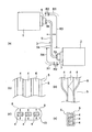
- FIG. 1 is a view showing a wire harness of the present invention.
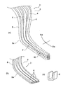
- FIG. 2 is a figure which concerns on the state of a high voltage electric wire
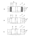
- FIG. 3 is a figure which concerns on the structure of a harness main body
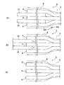
- FIG. 4 is a figure which concerns on manufacture of a wire harness.
- the wire harness of the present embodiment is not particularly limited, but is intended for a hybrid vehicle or an electric vehicle. Specifically, it is for a high voltage, and is wired to connect the motor and the inverter, wired to connect the inverter and the battery, or between devices (for example, electric (Including devices such as connection boxes). Below, the wire harness which connects a motor and an inverter is mentioned as an example, and is demonstrated.
- a motor 1 and an inverter 2 in an electric vehicle or a hybrid vehicle are electrically connected by a wire harness 3 (also referred to as a motor cable).
- the wire harness 3 is provided at a harness body 5 including a plurality of high-voltage electric wires 4, a motor-side connection portion 6 provided at one end (terminal portion) of the harness body 5, and the other end (terminal portion) of the harness body 5.
- the inverter side connection part 7 is comprised.
- the wire harness 3 actively transmits vibrations from the motor 1 and impacts from the vehicle to a predetermined range of the plurality of high-voltage wires 4 in the harness body 5, thereby causing vibration in the direction of the arrow in the figure. It can be done. This vibration can absorb vibrations and the like.
- the wire harness 3 is configured to have the vibration absorbing structure as described above. Hereinafter, each configuration of the wire harness 3 will be described.
- the harness body 5 includes a plurality of high-voltage wires 4 and a protective member 8 that collectively covers them.
- the plurality of high-voltage electric wires 4 have a shake allowable range R1 in which vibrations and shocks from the motor 1 are positively transmitted to cause shake.
- the shake allowable range R ⁇ b> 1 is set as a range that allows the shake of the plurality of high-voltage wires 4 in the middle of the harness body 5.
- the deflection allowable range R1 corresponds to the entire middle 5a of the harness body 5 in this embodiment. That is, in the present embodiment, the range excluding both terminal portions 5b of the harness body 5 is set as the shake allowable range R1.
- a vibration allowable range R1 is set on the vibration generation source side of the fixing point.
- the shake allowable range R1 refers to a range in which the above-described fixed point is not provided.
- both sides of the shake allowable range R1 are set as the terminal portion formation range R2 corresponding to the formation range of the terminal portion 5b.
- the allowable runout range R1 is set to be configured by an electric wire / individual runout range R3 and an electric wire / bundle runout range R4 (not limited to this configuration, but only in the electric wire / individual runout range R3. May be).
- the electric wire / individual shake range R3 and the electric wire / bundle run-out range R4 are continuous, and the electric wire / individual shake range R3 is arranged on the vibration source side. Details of the electric wire / individual fluctuation range R3 and the electric wire / bundle fluctuation range R4 will be described later.
- the high-voltage wires 4 are high-voltage wires (high-voltage cables), and three wires are used in this embodiment.
- the three high voltage electric wires 4 are all the same.
- the high-voltage electric wire 4 includes a conductor portion and a covering portion that covers the conductor portion.
- the conductor portion is not particularly limited, but is formed of a stranded wire conductor made of copper or aluminum. Alternatively, it is formed of a flat conductor or a round conductor which is also made of copper or aluminum. In addition, in the figure, it shows as the high voltage electric wire 4 containing a flat conductor (it shall be an example).
- the high-voltage electric wire 4 in the present embodiment has a configuration of a non-shielded electric wire (a case of using a shielded electric wire will be described later).
- the high voltage electric wire 4 is formed with a total length of a length corresponding to the distance between the motor 1 and the inverter 2 and a length necessary for the swing in the arrow direction in FIG. In other words, in the case of the present embodiment, it is formed with at least a length corresponding to the shake allowable range R1 and the terminal portion formation range R2.
- the plurality of high-voltage wires 4 are wired in such a state that each high-voltage wire 4 can swing individually.
- the high voltage electric wires 2 are wired so as not to be in close contact with each other so that the adjacent high voltage electric wires 4 can swing individually at a predetermined interval. It should be noted that the above-mentioned predetermined interval is arbitrary as long as individual swings are possible.
- the high-voltage wires 4 are wired so that they are in contact with each other. More specifically, in the vicinity of the boundary between the electric wire / individual fluctuation range R3 and the electric wire / bundle fluctuation range R4, the intervals between the plurality of high-voltage electric wires 4 that can be individually oscillated gradually become narrower. It is in a good state.
- the contact state is formed by stacking the high-voltage electric wires 4 one above the other as shown in FIG. 2 (a) or arranging them side by side as shown in FIG. 2 (b).
- the boundary between the electric wire / individual run-out range R3 and the electric wire / bundle run-out range R4 indicated by the reference symbol T is narrowed in height (lowered).
- a portion overlapping the upper and lower sides indicated by the reference sign W is narrowed (narrowed) in the width direction.
- an alignment maintaining member 9 as shown in FIG. 2 (c) may be used.
- the alignment maintaining member 9 is made of resin, for example, and is formed in a substantially U shape.
- the alignment maintaining member 9 is formed such that when the high voltage electric wire 4 is inserted inside the alignment maintaining member 9, the alignment maintaining member 9 can be held while maintaining the contact state and the alignment state.
- the protection member 8 is a member that collectively covers a plurality of high-voltage wires 4 as described above, and the high-voltage wires 4 are unshielded wires in this embodiment. Therefore, the electric wire protection function and the electromagnetic shielding function can be exhibited.
- the configuration of the protection member 8 will be described in detail with reference to FIG. 3A.
- the protection member 8 includes a braid 10 having a function as a shield member, and an exterior member 11 provided outside the braid 10. And the tape winding 12 for preventing the exterior member 11 from being loosened.
- the protective member 8 having such a configuration is provided as shown in FIGS. 1B to 1E and FIG. 2A.
- the plurality of high voltage electric wires 4 are “bukabuka” so as to cover the plurality of high voltage electric wires 4 while maintaining the individually swingable state. It is provided to cover.
- the electric wire / bundled run-out range R4 it is provided so as to be “tightly attached” to the plurality of bundled high-voltage electric wires 4. It is effective to wind the tape winding 12 tightly or tightly to provide it so that it “sticks tightly”.
- the high-voltage wire 4 can swing individually (freely swing) as shown by the arrows. ing.
- the braid 10 is formed by knitting a conductive ultrafine wire into a cylindrical shape. Inside the braid 10, a plurality of high-voltage electric wires 4 are inserted all at once. In the braid 10, the portion corresponding to the electric wire / individual deflection range R ⁇ b> 3 is stretched in the radial direction, and the portion corresponding to the electric wire / bundle deflection range R ⁇ b> 4 is in intimate contact with the high-voltage electric wire 4 (in close contact with the exterior member 11. The type of usage or the size that does not need to be stretched is used, and the portion corresponding to the wire / bundle run-out range R4 is narrowed and closely attached to the high-voltage wire 4 It is in the usage form.
- the braid 10 is not limited to the above, but may be formed into a cylindrical shape by winding a sheet.
- the exterior member 11 is provided as a member that exerts a protective function to the outside.
- the exterior member 11 is a sheet having wear resistance and flexibility.
- the exterior member 11 is wound around the outside of the braid 10.
- a twist tube is given as an example, and the tape winding 12 is applied at a predetermined position.
- the overall length of the exterior member 11 is slightly shorter than that of the braid 10, so that the braid 10 is exposed.
- the boundary portion where the braid 10 is exposed is formed with an acetate tube (not shown) by winding a tape made of acetate cloth, for example.
- a metal foil 14 (see FIG. 3B) may be used instead of the braid 10, and the exterior member 11 may be wound around the outside of the metal foil 14.
- the high-voltage electric wire 4 is not a non-shielded electric wire but a shielded electric wire 4 ′
- the exterior member 11 may be directly wound around the high-voltage electric wire 4 without providing the braid 10 or the metal foil 14 (FIG. 3 (c)).
- the protective member 8 is formed to have a length straddling the motor side connecting portion 6 and the inverter side connecting portion 7 (see FIG. 1A).
- the motor-side connecting portion 6 is grounded on the motor 1 side with a terminal fitting (not shown) provided at each end of the high-voltage electric wire 4, an insulating housing (not shown) for receiving and fixing the terminal fitting. And a metal shell (not shown) for connecting and fixing one end of the braid 10 to the ground portion.
- the motor-side connecting portion 6 has a known structure (it is a known structure, and thus detailed description thereof is omitted here).
- the inverter side connection portion 7 is configured in the same manner as the motor side connection portion 6. That is, the inverter-side connecting portion 7 includes a terminal fitting (not shown) provided at each end of the high-voltage electric wire 4, an insulating housing (not shown) for receiving and fixing the terminal fitting, and an inverter 2 side. An earth part (not shown) to be grounded and a metal shell (not shown) for connecting and fixing the other end of the braid 10 to the earth part are provided.
- the inverter-side connection portion 7 has a known structure (it is a well-known structure, and a detailed description thereof will be omitted here).
- the motor side connecting portion 6 and the inverter side connecting portion 7 are provided as connecting portions in the wire harness 3, and the configuration and the like change according to the usage pattern (routing) of the wire harness 3.
- the wire harness 3 sets an allowable runout range R1 for a plurality of high-voltage electric wires 4 and sets an electric wire / individual runout range R3 and an electric wire / bundle runout range R4 in the allowable runout range R1.
- a dummy electric wire 15 is provided between the high-voltage electric wires 4 in order to form a state in which the electric wires can be individually shaken.
- an intervening operation is performed (not only the dummy electric wire 15 but also a simple rod.
- the dummy electric wire 15 is provided so as to open the gap between the high-voltage electric wires 4.
- the sheet-like exterior member 11 is wound around the outside of the braid 10 and the tape winding 12 is applied to a desired position.
- the winding of the exterior member 11 is performed so as to maintain the individually swingable state in the electric wire / individual swing range R3, in other words, to maintain the “buzzy” state. Further, in the electric wire / bundled run-out range R4, it is performed so as to “stick tightly”.
- the wire harness 3 includes the motor 1 or the outside.
- vibration in the direction of the arrow occurs in a portion corresponding to the allowable vibration range R1 (particularly, the electric wire / individual vibration range R3). This vibration contributes to absorption of the vibration and the like. Therefore, even if the above-described shake occurs, a shake force that affects the inverter-side connecting portion 7 is not applied.
- the allowable swing range R ⁇ b> 1 (wire / individual swing range) set for the plurality of high-voltage wires 4 in the harness body 5. Since vibrations and impacts from the motor 1 and the like are positively transmitted to R3 and the electric wire / bundled runout range R4), vibrations and the like can be absorbed. If the vibration or the like can be absorbed as in the wire harness 3 of the present invention, it is possible to prevent the generation of abnormal noise or breakage.
- the high-voltage electric wires 4 in the electric wire / individual fluctuation range R3 are wired in a state where they can be individually shaken, the high-voltage electric wires 4 can be effectively shaken.
- the wire harness 3 of the present invention it is possible to reduce the height especially in the electric wire / bundle-like runout range R4, so that it is possible to consider in terms of the wiring space.
Landscapes
- Engineering & Computer Science (AREA)
- Microelectronics & Electronic Packaging (AREA)
- Architecture (AREA)
- Civil Engineering (AREA)
- Structural Engineering (AREA)
- Mechanical Engineering (AREA)
- Details Of Indoor Wiring (AREA)
- Insulated Conductors (AREA)
- Vibration Prevention Devices (AREA)
Abstract
Description
2…インバータ
3…ワイヤハーネス
4…高圧電線
4′…シールド電線
5…ハーネス本体
5a…中間
5b…端末部
6…モータ側接続部
7…インバータ側接続部
8…保護部材
9…整列維持部材
10…編組(シールド部材)
11…外装部材
12…テープ巻き
13…内部空間
14…金属箔
15…ダミーの電線
R1…振れ許容範囲(振れを許容する範囲)
R2…端末部形成範囲
R3…電線・個別振れ範囲
R4…電線・束状振れ範囲
Claims (4)
- 複数本の高圧電線を含むハーネス本体を備える車両用のワイヤハーネスにおいて、
前記ハーネス本体の中間は前記複数本の高圧電線の振れを許容する範囲を有し、
該振れを許容する範囲の一部又は全部においては前記複数本の高圧電線を個別に振れ可能に配線する
ことを特徴とするワイヤハーネス。 - 請求項1に記載のワイヤハーネスにおいて、
前記複数本の高圧電線として複数本のシールド電線を用いる
ことを特徴とするワイヤハーネス。 - 請求項1に記載のワイヤハーネスにおいて、
前記複数本の高圧電線として複数本の非シールド電線を用いる一方、前記ハーネス本体として前記複数本の非シールド電線を一括して覆うシールド部材を含む
ことを特徴とするワイヤハーネス。 - 請求項1ないし請求項3いずれか記載のワイヤハーネスにおいて、
前記ハーネス本体は前記個別に振れ可能な状態を保ちつつ前記複数本の高圧電線を覆う保護部材を含む
ことを特徴とするワイヤハーネス。
Priority Applications (3)
| Application Number | Priority Date | Filing Date | Title |
|---|---|---|---|
| CN201180018978.5A CN102859819B (zh) | 2010-04-15 | 2011-02-02 | 线束 |
| US13/634,413 US9083162B2 (en) | 2010-04-15 | 2011-02-02 | Wiring harness |
| EP11768659.2A EP2560257B1 (en) | 2010-04-15 | 2011-02-02 | Wire harness |
Applications Claiming Priority (2)
| Application Number | Priority Date | Filing Date | Title |
|---|---|---|---|
| JP2010093608A JP5607412B2 (ja) | 2010-04-15 | 2010-04-15 | ワイヤハーネス |
| JP2010-093608 | 2010-04-15 |
Publications (1)
| Publication Number | Publication Date |
|---|---|
| WO2011129137A1 true WO2011129137A1 (ja) | 2011-10-20 |
Family
ID=44798518
Family Applications (1)
| Application Number | Title | Priority Date | Filing Date |
|---|---|---|---|
| PCT/JP2011/052131 Ceased WO2011129137A1 (ja) | 2010-04-15 | 2011-02-02 | ワイヤハーネス |
Country Status (5)
| Country | Link |
|---|---|
| US (1) | US9083162B2 (ja) |
| EP (1) | EP2560257B1 (ja) |
| JP (1) | JP5607412B2 (ja) |
| CN (1) | CN102859819B (ja) |
| WO (1) | WO2011129137A1 (ja) |
Families Citing this family (7)
| Publication number | Priority date | Publication date | Assignee | Title |
|---|---|---|---|---|
| JP6191489B2 (ja) * | 2014-02-06 | 2017-09-06 | 株式会社オートネットワーク技術研究所 | 電磁シールド部品および電磁シールド部品付電線 |
| JP6256308B2 (ja) * | 2014-11-06 | 2018-01-10 | 住友電装株式会社 | ワイヤハーネスのシールド構造 |
| JP6610082B2 (ja) * | 2015-08-24 | 2019-11-27 | 富士ゼロックス株式会社 | 中継装置及び中継処理プログラム |
| DE102016107453A1 (de) * | 2016-04-22 | 2017-10-26 | Robert Bosch Automotive Steering Gmbh | Masseanbindung einer Schirmung einer elektrischen Leitung und Verfahren zur Masseanbindung einer Schirmung einer elektrischen Leitung |
| CN110521103B (zh) * | 2017-04-21 | 2021-09-14 | 三菱电机株式会社 | 电力转换装置的连接结构 |
| JP6974146B2 (ja) * | 2017-12-06 | 2021-12-01 | 矢崎総業株式会社 | 配索材の接続構造 |
| DE102023127635A1 (de) * | 2023-10-10 | 2025-04-10 | Bayerische Motoren Werke Aktiengesellschaft | Schallreduktionselement, Anordnung eines Schallreduktionselements an einem elektrisch betreibbaren Kraftwagen sowie Verfahren |
Citations (4)
| Publication number | Priority date | Publication date | Assignee | Title |
|---|---|---|---|---|
| JP2000152470A (ja) * | 1998-11-11 | 2000-05-30 | Nissan Motor Co Ltd | 電動車両の強電ハーネス配索構造 |
| JP2004224156A (ja) * | 2003-01-22 | 2004-08-12 | Honda Motor Co Ltd | 車両用電力ケーブル保持構造 |
| JP2005218189A (ja) * | 2004-01-28 | 2005-08-11 | Honda Motor Co Ltd | 車両用電力ケーブル保持構造、車両用電力ケーブルアッシの組み立て方法 |
| JP2008253017A (ja) | 2007-03-29 | 2008-10-16 | Toyota Motor Corp | ケーブル固定具 |
Family Cites Families (1)
| Publication number | Priority date | Publication date | Assignee | Title |
|---|---|---|---|---|
| JP2008178266A (ja) | 2007-01-22 | 2008-07-31 | Yazaki Corp | 給電装置 |
-
2010
- 2010-04-15 JP JP2010093608A patent/JP5607412B2/ja not_active Expired - Fee Related
-
2011
- 2011-02-02 CN CN201180018978.5A patent/CN102859819B/zh not_active Expired - Fee Related
- 2011-02-02 EP EP11768659.2A patent/EP2560257B1/en not_active Not-in-force
- 2011-02-02 WO PCT/JP2011/052131 patent/WO2011129137A1/ja not_active Ceased
- 2011-02-02 US US13/634,413 patent/US9083162B2/en not_active Expired - Fee Related
Patent Citations (4)
| Publication number | Priority date | Publication date | Assignee | Title |
|---|---|---|---|---|
| JP2000152470A (ja) * | 1998-11-11 | 2000-05-30 | Nissan Motor Co Ltd | 電動車両の強電ハーネス配索構造 |
| JP2004224156A (ja) * | 2003-01-22 | 2004-08-12 | Honda Motor Co Ltd | 車両用電力ケーブル保持構造 |
| JP2005218189A (ja) * | 2004-01-28 | 2005-08-11 | Honda Motor Co Ltd | 車両用電力ケーブル保持構造、車両用電力ケーブルアッシの組み立て方法 |
| JP2008253017A (ja) | 2007-03-29 | 2008-10-16 | Toyota Motor Corp | ケーブル固定具 |
Non-Patent Citations (1)
| Title |
|---|
| See also references of EP2560257A4 * |
Also Published As
| Publication number | Publication date |
|---|---|
| CN102859819B (zh) | 2018-06-19 |
| JP2011229196A (ja) | 2011-11-10 |
| EP2560257A1 (en) | 2013-02-20 |
| US9083162B2 (en) | 2015-07-14 |
| EP2560257B1 (en) | 2016-04-20 |
| US20130026826A1 (en) | 2013-01-31 |
| EP2560257A4 (en) | 2014-01-22 |
| JP5607412B2 (ja) | 2014-10-15 |
| CN102859819A (zh) | 2013-01-02 |
Similar Documents
| Publication | Publication Date | Title |
|---|---|---|
| JP5425508B2 (ja) | モーターケーブル装置、及び、モーターケーブル装置のケーブル本体製造方法 | |
| JP5425507B2 (ja) | モーターケーブル装置、及び、モーターケーブル装置に用いる樹脂部品 | |
| JP5607412B2 (ja) | ワイヤハーネス | |
| JP5431045B2 (ja) | モーターケーブル装置 | |
| JP5350323B2 (ja) | 編組シールド部材、編組シールド部材の製造方法、及びワイヤハーネス | |
| JP5491224B2 (ja) | ワイヤハーネス | |
| JP5758087B2 (ja) | ワイヤハーネス | |
| JP5722572B2 (ja) | ワイヤハーネス | |
| JP5927692B2 (ja) | ワイヤハーネス | |
| JP5766415B2 (ja) | ワイヤハーネス | |
| WO2014203979A1 (ja) | ワイヤハーネス | |
| JP6174628B2 (ja) | ワイヤーハーネス及び電線保持部材 | |
| JP2015022807A (ja) | 差動伝送ケーブルおよび多対差動伝送ケーブル | |
| JP6239882B2 (ja) | ワイヤハーネス | |
| JP5835893B2 (ja) | ワイヤハーネス | |
| CN107464617B (zh) | 线束 | |
| JP6163699B2 (ja) | ワイヤハーネス | |
| JP6127312B2 (ja) | ワイヤハーネス | |
| JP2018026229A (ja) | ワイヤーハーネス | |
| JP2013093144A (ja) | ワイヤーハーネス | |
| JPH11275728A (ja) | プロテクタ |
Legal Events
| Date | Code | Title | Description |
|---|---|---|---|
| WWE | Wipo information: entry into national phase |
Ref document number: 201180018978.5 Country of ref document: CN |
|
| 121 | Ep: the epo has been informed by wipo that ep was designated in this application |
Ref document number: 11768659 Country of ref document: EP Kind code of ref document: A1 |
|
| WWE | Wipo information: entry into national phase |
Ref document number: 13634413 Country of ref document: US |
|
| WWE | Wipo information: entry into national phase |
Ref document number: 1201005428 Country of ref document: TH |
|
| NENP | Non-entry into the national phase |
Ref country code: DE |
|
| WWE | Wipo information: entry into national phase |
Ref document number: 2011768659 Country of ref document: EP |