WO2011129148A1 - 水素吸蔵合金及びこれを用いた水素センサ - Google Patents
水素吸蔵合金及びこれを用いた水素センサ Download PDFInfo
- Publication number
- WO2011129148A1 WO2011129148A1 PCT/JP2011/053677 JP2011053677W WO2011129148A1 WO 2011129148 A1 WO2011129148 A1 WO 2011129148A1 JP 2011053677 W JP2011053677 W JP 2011053677W WO 2011129148 A1 WO2011129148 A1 WO 2011129148A1
- Authority
- WO
- WIPO (PCT)
- Prior art keywords
- hydrogen
- alloy
- layer
- catalyst layer
- light control
- Prior art date
- Legal status (The legal status is an assumption and is not a legal conclusion. Google has not performed a legal analysis and makes no representation as to the accuracy of the status listed.)
- Ceased
Links
Images


Classifications
-
- G—PHYSICS
- G01—MEASURING; TESTING
- G01N—INVESTIGATING OR ANALYSING MATERIALS BY DETERMINING THEIR CHEMICAL OR PHYSICAL PROPERTIES
- G01N21/00—Investigating or analysing materials by the use of optical means, i.e. using sub-millimetre waves, infrared, visible or ultraviolet light
- G01N21/17—Systems in which incident light is modified in accordance with the properties of the material investigated
- G01N21/25—Colour; Spectral properties, i.e. comparison of effect of material on the light at two or more different wavelengths or wavelength bands
- G01N21/29—Colour; Spectral properties, i.e. comparison of effect of material on the light at two or more different wavelengths or wavelength bands using visual detection
-
- C—CHEMISTRY; METALLURGY
- C01—INORGANIC CHEMISTRY
- C01B—NON-METALLIC ELEMENTS; COMPOUNDS THEREOF; METALLOIDS OR COMPOUNDS THEREOF NOT COVERED BY SUBCLASS C01C
- C01B3/00—Hydrogen; Gaseous mixtures containing hydrogen; Separation of hydrogen from mixtures containing it; Purification of hydrogen; Reversible storage of hydrogen
- C01B3/0005—Reversible storage of hydrogen, e.g. by hydrogen getters or electrodes
- C01B3/001—Reversible storage of hydrogen, e.g. by hydrogen getters or electrodes characterised by the uptaking media; Treatment thereof
- C01B3/0018—Inorganic elements or compounds, e.g. oxides, nitrides, borohydrides or zeolites; Solutions thereof
- C01B3/0031—Intermetallic compounds; Metal alloys
- C01B3/0042—Intermetallic compounds; Metal alloys only containing magnesium and nickel
-
- C—CHEMISTRY; METALLURGY
- C01—INORGANIC CHEMISTRY
- C01B—NON-METALLIC ELEMENTS; COMPOUNDS THEREOF; METALLOIDS OR COMPOUNDS THEREOF NOT COVERED BY SUBCLASS C01C
- C01B3/00—Hydrogen; Gaseous mixtures containing hydrogen; Separation of hydrogen from mixtures containing it; Purification of hydrogen; Reversible storage of hydrogen
- C01B3/0005—Reversible storage of hydrogen, e.g. by hydrogen getters or electrodes
- C01B3/001—Reversible storage of hydrogen, e.g. by hydrogen getters or electrodes characterised by the uptaking media; Treatment thereof
- C01B3/0078—Composite solid storage media, e.g. mixtures of polymers and metal hydrides, coated solid compounds or structurally heterogeneous solid compounds
-
- C—CHEMISTRY; METALLURGY
- C22—METALLURGY; FERROUS OR NON-FERROUS ALLOYS; TREATMENT OF ALLOYS OR NON-FERROUS METALS
- C22C—ALLOYS
- C22C1/00—Making non-ferrous alloys
-
- C—CHEMISTRY; METALLURGY
- C22—METALLURGY; FERROUS OR NON-FERROUS ALLOYS; TREATMENT OF ALLOYS OR NON-FERROUS METALS
- C22C—ALLOYS
- C22C16/00—Alloys based on zirconium
-
- C—CHEMISTRY; METALLURGY
- C22—METALLURGY; FERROUS OR NON-FERROUS ALLOYS; TREATMENT OF ALLOYS OR NON-FERROUS METALS
- C22C—ALLOYS
- C22C23/00—Alloys based on magnesium
-
- G—PHYSICS
- G01—MEASURING; TESTING
- G01N—INVESTIGATING OR ANALYSING MATERIALS BY DETERMINING THEIR CHEMICAL OR PHYSICAL PROPERTIES
- G01N21/00—Investigating or analysing materials by the use of optical means, i.e. using sub-millimetre waves, infrared, visible or ultraviolet light
- G01N21/75—Systems in which material is subjected to a chemical reaction, the progress or the result of the reaction being investigated
- G01N21/77—Systems in which material is subjected to a chemical reaction, the progress or the result of the reaction being investigated by observing the effect on a chemical indicator
- G01N21/78—Systems in which material is subjected to a chemical reaction, the progress or the result of the reaction being investigated by observing the effect on a chemical indicator producing a change of colour
- G01N21/783—Systems in which material is subjected to a chemical reaction, the progress or the result of the reaction being investigated by observing the effect on a chemical indicator producing a change of colour for analysing gases
-
- G—PHYSICS
- G01—MEASURING; TESTING
- G01N—INVESTIGATING OR ANALYSING MATERIALS BY DETERMINING THEIR CHEMICAL OR PHYSICAL PROPERTIES
- G01N33/00—Investigating or analysing materials by specific methods not covered by groups G01N1/00 - G01N31/00
- G01N33/0004—Gaseous mixtures, e.g. polluted air
- G01N33/0009—General constructional details of gas analysers, e.g. portable test equipment
- G01N33/0027—General constructional details of gas analysers, e.g. portable test equipment concerning the detector
- G01N33/0036—General constructional details of gas analysers, e.g. portable test equipment concerning the detector specially adapted to detect a particular component
- G01N33/005—H2
-
- G—PHYSICS
- G01—MEASURING; TESTING
- G01N—INVESTIGATING OR ANALYSING MATERIALS BY DETERMINING THEIR CHEMICAL OR PHYSICAL PROPERTIES
- G01N21/00—Investigating or analysing materials by the use of optical means, i.e. using sub-millimetre waves, infrared, visible or ultraviolet light
- G01N21/75—Systems in which material is subjected to a chemical reaction, the progress or the result of the reaction being investigated
- G01N21/77—Systems in which material is subjected to a chemical reaction, the progress or the result of the reaction being investigated by observing the effect on a chemical indicator
- G01N2021/7769—Measurement method of reaction-produced change in sensor
- G01N2021/7783—Transmission, loss
-
- G—PHYSICS
- G01—MEASURING; TESTING
- G01N—INVESTIGATING OR ANALYSING MATERIALS BY DETERMINING THEIR CHEMICAL OR PHYSICAL PROPERTIES
- G01N21/00—Investigating or analysing materials by the use of optical means, i.e. using sub-millimetre waves, infrared, visible or ultraviolet light
-
- G—PHYSICS
- G01—MEASURING; TESTING
- G01N—INVESTIGATING OR ANALYSING MATERIALS BY DETERMINING THEIR CHEMICAL OR PHYSICAL PROPERTIES
- G01N21/00—Investigating or analysing materials by the use of optical means, i.e. using sub-millimetre waves, infrared, visible or ultraviolet light
- G01N21/17—Systems in which incident light is modified in accordance with the properties of the material investigated
- G01N21/59—Transmissivity
-
- Y—GENERAL TAGGING OF NEW TECHNOLOGICAL DEVELOPMENTS; GENERAL TAGGING OF CROSS-SECTIONAL TECHNOLOGIES SPANNING OVER SEVERAL SECTIONS OF THE IPC; TECHNICAL SUBJECTS COVERED BY FORMER USPC CROSS-REFERENCE ART COLLECTIONS [XRACs] AND DIGESTS
- Y02—TECHNOLOGIES OR APPLICATIONS FOR MITIGATION OR ADAPTATION AGAINST CLIMATE CHANGE
- Y02E—REDUCTION OF GREENHOUSE GAS [GHG] EMISSIONS, RELATED TO ENERGY GENERATION, TRANSMISSION OR DISTRIBUTION
- Y02E60/00—Enabling technologies; Technologies with a potential or indirect contribution to GHG emissions mitigation
- Y02E60/30—Hydrogen technology
- Y02E60/32—Hydrogen storage
-
- Y—GENERAL TAGGING OF NEW TECHNOLOGICAL DEVELOPMENTS; GENERAL TAGGING OF CROSS-SECTIONAL TECHNOLOGIES SPANNING OVER SEVERAL SECTIONS OF THE IPC; TECHNICAL SUBJECTS COVERED BY FORMER USPC CROSS-REFERENCE ART COLLECTIONS [XRACs] AND DIGESTS
- Y02—TECHNOLOGIES OR APPLICATIONS FOR MITIGATION OR ADAPTATION AGAINST CLIMATE CHANGE
- Y02E—REDUCTION OF GREENHOUSE GAS [GHG] EMISSIONS, RELATED TO ENERGY GENERATION, TRANSMISSION OR DISTRIBUTION
- Y02E60/00—Enabling technologies; Technologies with a potential or indirect contribution to GHG emissions mitigation
- Y02E60/30—Hydrogen technology
- Y02E60/50—Fuel cells
-
- Y—GENERAL TAGGING OF NEW TECHNOLOGICAL DEVELOPMENTS; GENERAL TAGGING OF CROSS-SECTIONAL TECHNOLOGIES SPANNING OVER SEVERAL SECTIONS OF THE IPC; TECHNICAL SUBJECTS COVERED BY FORMER USPC CROSS-REFERENCE ART COLLECTIONS [XRACs] AND DIGESTS
- Y10—TECHNICAL SUBJECTS COVERED BY FORMER USPC
- Y10T—TECHNICAL SUBJECTS COVERED BY FORMER US CLASSIFICATION
- Y10T436/00—Chemistry: analytical and immunological testing
- Y10T436/21—Hydrocarbon
-
- Y—GENERAL TAGGING OF NEW TECHNOLOGICAL DEVELOPMENTS; GENERAL TAGGING OF CROSS-SECTIONAL TECHNOLOGIES SPANNING OVER SEVERAL SECTIONS OF THE IPC; TECHNICAL SUBJECTS COVERED BY FORMER USPC CROSS-REFERENCE ART COLLECTIONS [XRACs] AND DIGESTS
- Y10—TECHNICAL SUBJECTS COVERED BY FORMER USPC
- Y10T—TECHNICAL SUBJECTS COVERED BY FORMER US CLASSIFICATION
- Y10T436/00—Chemistry: analytical and immunological testing
- Y10T436/22—Hydrogen, per se
Definitions
- a thin film layer (thin film) having a dimming action is formed on the surface of a substrate such as glass or acrylic resin with a magnesium / nickel alloy, and this thin film layer is formed of palladium.
- a hydrogen sensor has been developed that rapidly hydrogenates (changes the physical properties of the thin film layer) by the action of a catalyst layer (catalyst film). This hydrogen sensor leaked into the atmosphere by detecting changes in the optical reflectance (hereinafter referred to as “reflectance” or “light transmittance”) associated with hydrogenation of the thin film layer. Hydrogen gas can be detected, and since the thin film layer is reversibly hydrogenated at room temperature, the leaked hydrogen gas can be detected safely and quickly.
- An object of the present invention is to provide a hydrogen storage alloy capable of quickly releasing or dehydrogenating hydrogen after being occluded or hydrogenated, and a hydrogen sensor using the same.
- the present invention is a hydrogen storage alloy comprising an Mg—Ni alloy and a Zr—Ti alloy.
- the hydrogen storage alloy consists only of Mg—Ni alloy and Zr—Ti—Mn alloy.
- the present invention also provides a substrate, a hydrogen reaction layer provided on the substrate and including the Mg—Ni alloy and the Zr—Ti alloy, and provided on the hydrogen reaction layer.
- the Mg—Ni alloy and the Zr—Ti alloy are dispersed and mixed.
- the hydrogen reaction layer is formed of the light control layer formed of the Mg—Ni based alloy and the Zr—Ti based alloy, and promotes dehydrogenation of the Mg—Ni based alloy. 2 catalyst layers.
- the Mg—Ni alloy and the Zr—Ti alloy are used as the hydrogen reaction layer that reacts with hydrogen, the hydrogen occluded in the Mg—Ni alloy can be quickly released. . That is, dehydrogenation can be accelerated. Therefore, the operation
- the hydrogen reaction layer is a dispersion-mixed Mg—Ni alloy and Zr—Ti alloy
- the hydrogen absorbed in the Mg—Ni alloy can be quickly released. Can do. That is, dehydrogenation can be accelerated. Therefore, the operation
- the light control layer can be quickly dehydrogenated by the action of the second catalyst layer, and the light control layer repeats hydrogenation and dehydrogenation to repeat the first catalyst layer. It can be prevented that it bites into the surface and deposits on the surface as it is.
- the hydrogen reaction layer 3 includes an Mg—Ni alloy and a Zr—Ti alloy.
- This is the hydrogen storage alloy according to the present invention.
- the storage and release of hydrogen is mainly performed by the Mg—Ni-based alloy.
- the Zr—Ti-based alloy By including the Zr—Ti-based alloy here, the hydrogen stored in the Mg—Ni-based alloy can be quickly released. That is, dehydrogenation can be accelerated.
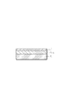
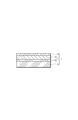
- the hydrogen sensor 1 shown in FIGS. 1 to 4 uses such a hydrogen storage alloy as the hydrogen reaction layer 3.
- an Mg—Ni alloy and a Zr—Ti—Mn alloy are dispersed and mixed to form a hydrogen reaction layer 3 (Example 1).
- This mixing is performed as follows. First, after cleaning the substrate 2, it is set in a vacuum apparatus and evacuated. Then, Mg—Ni and Zr—Ti—Mn targets are sputtered simultaneously for 1 minute. Sputtering is performed by applying a power of 100 W to Mg—Ni and 30 W to Zr—Ti—Mn by direct current sputtering.
- FIG. 4 two second catalyst layers 6 are formed, and the light control layer 5 is sandwiched between the second catalyst layers 6.
- any structure may be employed as long as the Mg—Ni alloy and the Zr—Ti—Mn alloy are disposed between the substrate 2 and the first catalyst layer 4.
- the Mg—Ni alloy and the Zr—Ti—Mn alloy were mixed and dispersed by simultaneous sputtering for 1 minute. As described above, even if the hydrogen reaction layer is formed by dispersing and mixing the Mg—Ni alloy and the Zr—Ti alloy, the hydrogen occluded in the Mg—Ni alloy can be rapidly released. That is, dehydrogenation can be accelerated. Therefore, the operation
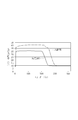
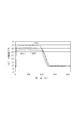
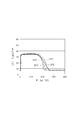
- the light transmittance is lower in Example 1, there is no problem even if the transmittance of the hydrogen sensor is slightly lowered if the transparency of the sensor can be recognized with the naked eye.
- the transmittance of Example 1 is about 35%, but there is no problem in use.
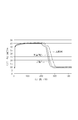
- FIG. 8 is a graph comparing Example 2 and Example 3 with a comparative example.
- the solid line indicates Example 2
- the broken line indicates Example 3
- the alternate long and short dash line indicates a comparative example.
- the light transmittance is almost the same in both cases.
- the dehydrogenation was completed in about 270 seconds for Example 2, about 280 seconds for Example 3, and about 300 seconds for Comparative Example. That is, the light control layer made of Mg—Ni-based alloy and the two catalyst layers made of Zr—Ti-based alloy are separately provided and disposed between the base and the first catalyst layer. Hydrogen stored in the light control layer can be quickly released. In other words, dehydrogenation can be accelerated.
- work which repeatedly detects hydrogen using a hydrogen sensor can be performed rapidly.
- the thickness of the first catalyst layer 4 was 4 nm
- the light control layer 5 was 20 nm
- the second catalyst layer 6 was 1 nm.
- substantially the same experimental results are obtained even when the second catalyst layer 6 is 2 nm.
- Example 4 the effects of both Example 2 and Example 3 can be obtained. That is, the time required for dehydrogenation is faster than that of the comparative example, and a buffer layer can also be provided. From the above experimental results, it has been clarified that the inclusion of the Zr—Ti—Mn alloy accelerates the dehydrogenation. In particular, Example 1 is most excellent from the viewpoint of dehydrogenation.
- the hydrogen sensor 1 uses the switching function of the light control layer 5, for example, a shielding object for the purpose of privacy protection, a decoration or a toy using a change between a mirror state and a transparent state, etc. In addition to the purpose of hydrogen detection, it can be applied for various purposes.
Landscapes
- Chemical & Material Sciences (AREA)
- Engineering & Computer Science (AREA)
- Organic Chemistry (AREA)
- Physics & Mathematics (AREA)
- Life Sciences & Earth Sciences (AREA)
- Health & Medical Sciences (AREA)
- Chemical Kinetics & Catalysis (AREA)
- Combustion & Propulsion (AREA)
- Pathology (AREA)
- Immunology (AREA)
- General Physics & Mathematics (AREA)
- General Health & Medical Sciences (AREA)
- Biochemistry (AREA)
- Analytical Chemistry (AREA)
- Inorganic Chemistry (AREA)
- Materials Engineering (AREA)
- Mechanical Engineering (AREA)
- Metallurgy (AREA)
- Plasma & Fusion (AREA)
- Food Science & Technology (AREA)
- Medicinal Chemistry (AREA)
- Spectroscopy & Molecular Physics (AREA)
- Investigating Or Analysing Materials By The Use Of Chemical Reactions (AREA)
- Investigating Or Analysing Materials By Optical Means (AREA)
- Investigating Or Analyzing Materials By The Use Of Fluid Adsorption Or Reactions (AREA)
Abstract
Description
好ましくは、水素吸蔵合金は、Mg-Ni合金とZr-Ti-Mn合金のみからなる。
好ましくは、前記水素反応層は、前記Mg-Ni系合金で形成された調光層と、前記Zr-Ti系合金で形成され、前記Mg-Ni系合金の脱水素化を促進するための第2の触媒層とを有する。
好ましくは、前記第2の触媒層は、前記調光層と前記第1の触媒層との間に配置されている。
好ましくは、前記第2の触媒層は、前記調光層と前記第1の触媒層との間及び前記調光層と前記基板との間に配置されている。
また、本発明によれば、Mg-Ni合金とZr-Ti-Mn合金を組み合わせたものが、脱水素化を迅速に行えることが実験により確認されている。
また、本発明によれば、第2の触媒層を調光層と第1の触媒層との間に配置するが、この場合に脱水素化が迅速に行えることが実験により確認されている。また、第2の触媒層は、調光層が水素化及び脱水素化により膨脹及び収縮を繰り返して表面に析出することを防止するバッファ層としても利用できる。特に、Mgはすぐに酸化されるため、この酸化防止の観点からも好適である。
基板2は、透明の板材からなる。例えば、アクリル、プラスチック、透明シート、ガラス等である。
以上の構成で、水素を測定することができる。すなわち、水素を含んだ雰囲気にさらすことで水素反応層3の水素化(水素吸蔵)が起こり、金属状態から透明状態に変化する。一方で、水素を含まず酸素を含んだ雰囲気にさらすことで脱水素化(水素放出)が起こり、透明状態から金属状態に変化する。
以上の実験結果より、Zr-Ti-Mn合金を含めたほうが、脱水素化を速めることが明らかになったが、特に実施例1が脱水素化の観点から最も優れている。
2 基板
3 水素反応層
4 第1の触媒層
5 調光層
6 第2の触媒層
Claims (8)
- Mg-Ni系合金とZr-Ti系合金とを含むことを特徴とする水素吸蔵合金。
- Mg-Ni合金とZr-Ti-Mn合金のみからなることを特徴とする請求項1に記載の水素吸蔵合金。
- 基板と、
該基板上に設けられ、前記Mg-Ni系合金と前記Zr-Ti系合金とを含む水素反応層と、
該水素反応層上に設けられ、前記Mg-Ni系合金の水素化を促進するための第1の触媒層とを備えたことを特徴とする請求項1に記載の水素吸蔵合金を用いた水素センサ。 - 前記水素反応層は、前記Mg-Ni系合金と前記Zr-Ti系合金とが分散混合されていることを特徴とする請求項3に記載の水素センサ。
- 前記水素反応層は、前記Mg-Ni系合金で形成された調光層と、前記Zr-Ti系合金で形成され、前記Mg-Ni系合金の脱水素化を促進するための第2の触媒層とを有することを特徴とする請求項3に記載の水素センサ。
- 前記第2の触媒層は、前記調光層と前記基板との間に配置されていることを特徴とする請求項5に記載の水素センサ。
- 前記第2の触媒層は、前記調光層と前記第1の触媒層との間に配置されていることを特徴とする請求項5に記載の水素センサ。
- 前記第2の触媒層は、前記調光層と前記第1の触媒層との間及び前記調光層と前記基板との間に配置されていることを特徴とする請求項5に記載の水素センサ。
Priority Applications (5)
| Application Number | Priority Date | Filing Date | Title |
|---|---|---|---|
| CN2011800280789A CN102933729A (zh) | 2010-04-14 | 2011-02-21 | 储氢合金及使用该储氢合金的氢传感器 |
| US13/641,373 US8758691B2 (en) | 2010-04-14 | 2011-02-21 | Hydrogen-absorbing alloy and hydrogen sensor using the alloy |
| EP11768669.1A EP2559778B1 (en) | 2010-04-14 | 2011-02-21 | Hydrogen sensor using hydrogen-absorbing alloy |
| CA2795051A CA2795051C (en) | 2010-04-14 | 2011-02-21 | Hydrogen-absorbing alloy and hydrogen sensor using the alloy |
| KR1020127026566A KR101724782B1 (ko) | 2010-04-14 | 2011-02-21 | 수소흡장 합금 및 이것을 사용한 수소센서 |
Applications Claiming Priority (2)
| Application Number | Priority Date | Filing Date | Title |
|---|---|---|---|
| JP2010093135A JP5789357B2 (ja) | 2010-04-14 | 2010-04-14 | 水素センサ |
| JP2010-093135 | 2010-04-14 |
Publications (1)
| Publication Number | Publication Date |
|---|---|
| WO2011129148A1 true WO2011129148A1 (ja) | 2011-10-20 |
Family
ID=44798527
Family Applications (1)
| Application Number | Title | Priority Date | Filing Date |
|---|---|---|---|
| PCT/JP2011/053677 Ceased WO2011129148A1 (ja) | 2010-04-14 | 2011-02-21 | 水素吸蔵合金及びこれを用いた水素センサ |
Country Status (7)
| Country | Link |
|---|---|
| US (1) | US8758691B2 (ja) |
| EP (1) | EP2559778B1 (ja) |
| JP (1) | JP5789357B2 (ja) |
| KR (1) | KR101724782B1 (ja) |
| CN (1) | CN102933729A (ja) |
| CA (1) | CA2795051C (ja) |
| WO (1) | WO2011129148A1 (ja) |
Cited By (2)
| Publication number | Priority date | Publication date | Assignee | Title |
|---|---|---|---|---|
| JP2013096528A (ja) * | 2011-11-02 | 2013-05-20 | Denso Corp | 通信装置 |
| CN105060248A (zh) * | 2015-07-17 | 2015-11-18 | 北京浩运金能科技有限公司 | 一种氢气净化装置 |
Families Citing this family (17)
| Publication number | Priority date | Publication date | Assignee | Title |
|---|---|---|---|---|
| US9045335B2 (en) * | 2010-08-18 | 2015-06-02 | The Governors Of The University Of Alberta | Kinetic stabilization of magnesium hydride |
| JP5967568B2 (ja) * | 2012-05-24 | 2016-08-10 | 国立研究開発法人産業技術総合研究所 | 水素吸放出合金、水素吸放出体、及び水素センサー。 |
| JP6077906B2 (ja) | 2013-03-28 | 2017-02-08 | 株式会社アツミテック | スパッタリング装置 |
| CN104730114A (zh) * | 2013-12-19 | 2015-06-24 | 中国科学院上海硅酸盐研究所 | 一种用于氢气传感器的镁合金薄膜及其制备方法 |
| EP2988116B8 (en) | 2014-08-19 | 2017-06-07 | ABB Schweiz AG | Optical sensor for detecting hydrogen in fluid and use of thin alloy film in the hydrogen sensor |
| WO2016026803A1 (en) * | 2014-08-19 | 2016-02-25 | Abb Technology Ag | Hydrogen sensor having a protection layer |
| JP6757176B2 (ja) | 2015-05-21 | 2020-09-16 | 日東電工株式会社 | 調光フィルムおよびその製造方法、ならびに調光素子 |
| JP6900156B2 (ja) * | 2015-05-21 | 2021-07-07 | 日東電工株式会社 | 調光フィルムおよびその製造方法、ならびに調光素子 |
| JP2017182062A (ja) * | 2016-03-25 | 2017-10-05 | 日東電工株式会社 | 調光フィルムの製造方法 |
| US10247997B2 (en) | 2016-08-16 | 2019-04-02 | Cardinal Cg Company | Switchable hydride smart window and the methods for producing the same |
| JP6697781B2 (ja) * | 2016-09-23 | 2020-05-27 | 国立研究開発法人産業技術総合研究所 | 水素感知素子及び水素センサー |
| KR20190040986A (ko) | 2016-09-23 | 2019-04-19 | 고쿠리츠켄큐카이하츠호진 상교기쥬츠 소고켄큐쇼 | 수소 흡장체, 가스크로믹형 조광 소자, 수소 감지 소자 및 수소 센서 |
| EP3640564A4 (en) * | 2017-06-15 | 2020-12-30 | Clean Planet Inc. | HEAT GENERATING DEVICE AND METHOD FOR HEAT GENERATION |
| CN113167504B (zh) | 2018-12-11 | 2024-08-02 | 绿净星球股份有限公司 | 热利用系统及发热装置 |
| JP2021107744A (ja) * | 2018-12-11 | 2021-07-29 | 株式会社クリーンプラネット | 熱利用システムおよび発熱装置 |
| JP7217458B2 (ja) * | 2019-02-20 | 2023-02-03 | 国立大学法人横浜国立大学 | ナノ構造体アレイ、水素検出用素子及び水素検出装置 |
| DE102020111959A1 (de) | 2020-05-04 | 2021-11-04 | MAX-PLANCK-Gesellschaft zur Förderung der Wissenschaften e.V. | Verfahren und Messvorrichtung zur Untersuchung der Wasserstoffpermeabilität eines Untersuchungsgegenstands |
Citations (3)
| Publication number | Priority date | Publication date | Assignee | Title |
|---|---|---|---|---|
| JPH10259436A (ja) * | 1997-03-21 | 1998-09-29 | Toshiba Corp | 水素吸蔵合金,その製造方法およびニッケル水素二次電池 |
| JP2004346418A (ja) | 2003-05-26 | 2004-12-09 | Hitachi Cable Ltd | 複合水素吸蔵合金、燃料電池用水素吸蔵タンク、多層構造体、および複合水素吸蔵合金の製造方法 |
| JP2008298724A (ja) * | 2007-06-04 | 2008-12-11 | Atsumi Tec:Kk | 水素センサ |
Family Cites Families (6)
| Publication number | Priority date | Publication date | Assignee | Title |
|---|---|---|---|---|
| US6964826B2 (en) * | 1999-04-12 | 2005-11-15 | Ovonic Battery Company, Inc. | Coated catalytic material with a metal phase in contact with a grain boundary oxide |
| JP4147462B2 (ja) * | 2002-08-07 | 2008-09-10 | トヨタ自動車株式会社 | 多層構造水素吸蔵体 |
| US7404842B1 (en) | 2003-01-23 | 2008-07-29 | Jesse Wainright | Microfabricated hydrogen storage device and metal hydride fuel cell/battery |
| US20050186117A1 (en) * | 2004-02-19 | 2005-08-25 | Hiroyuki Uchiyama | Gas detecting method and gas sensors |
| JP2005326269A (ja) | 2004-05-14 | 2005-11-24 | Hitachi Cable Ltd | ガス検知の方法およびガス検知装置 |
| JP2007248367A (ja) * | 2006-03-17 | 2007-09-27 | Atsumi Tec:Kk | 水素ガス検知装置 |
-
2010
- 2010-04-14 JP JP2010093135A patent/JP5789357B2/ja active Active
-
2011
- 2011-02-21 CA CA2795051A patent/CA2795051C/en active Active
- 2011-02-21 WO PCT/JP2011/053677 patent/WO2011129148A1/ja not_active Ceased
- 2011-02-21 CN CN2011800280789A patent/CN102933729A/zh active Pending
- 2011-02-21 EP EP11768669.1A patent/EP2559778B1/en active Active
- 2011-02-21 US US13/641,373 patent/US8758691B2/en active Active
- 2011-02-21 KR KR1020127026566A patent/KR101724782B1/ko active Active
Patent Citations (3)
| Publication number | Priority date | Publication date | Assignee | Title |
|---|---|---|---|---|
| JPH10259436A (ja) * | 1997-03-21 | 1998-09-29 | Toshiba Corp | 水素吸蔵合金,その製造方法およびニッケル水素二次電池 |
| JP2004346418A (ja) | 2003-05-26 | 2004-12-09 | Hitachi Cable Ltd | 複合水素吸蔵合金、燃料電池用水素吸蔵タンク、多層構造体、および複合水素吸蔵合金の製造方法 |
| JP2008298724A (ja) * | 2007-06-04 | 2008-12-11 | Atsumi Tec:Kk | 水素センサ |
Non-Patent Citations (1)
| Title |
|---|
| See also references of EP2559778A4 |
Cited By (2)
| Publication number | Priority date | Publication date | Assignee | Title |
|---|---|---|---|---|
| JP2013096528A (ja) * | 2011-11-02 | 2013-05-20 | Denso Corp | 通信装置 |
| CN105060248A (zh) * | 2015-07-17 | 2015-11-18 | 北京浩运金能科技有限公司 | 一种氢气净化装置 |
Also Published As
| Publication number | Publication date |
|---|---|
| EP2559778A1 (en) | 2013-02-20 |
| KR20130032868A (ko) | 2013-04-02 |
| CA2795051C (en) | 2019-01-08 |
| US8758691B2 (en) | 2014-06-24 |
| US20130028791A1 (en) | 2013-01-31 |
| CN102933729A (zh) | 2013-02-13 |
| JP2011219841A (ja) | 2011-11-04 |
| JP5789357B2 (ja) | 2015-10-07 |
| EP2559778A4 (en) | 2013-12-18 |
| CA2795051A1 (en) | 2011-10-20 |
| KR101724782B1 (ko) | 2017-04-18 |
| EP2559778B1 (en) | 2018-08-29 |
Similar Documents
| Publication | Publication Date | Title |
|---|---|---|
| JP5789357B2 (ja) | 水素センサ | |
| JP5900954B2 (ja) | 反射型調光素子、該反射型調光素子を用いた反射型調光部材、及び、複層ガラス。 | |
| JP6757176B2 (ja) | 調光フィルムおよびその製造方法、ならびに調光素子 | |
| JP5164435B2 (ja) | 水素センサ | |
| US20250027192A1 (en) | Fluorocarbon/palladium/magnesium-scandium hydrogen-chromic film and preparation method thereof | |
| Slack et al. | Metal hydride switchable mirrors: Factors influencing dynamic range and stability | |
| JP6900156B2 (ja) | 調光フィルムおよびその製造方法、ならびに調光素子 | |
| TW201736927A (zh) | 調光膜之製造方法 | |
| WO2016186130A1 (ja) | 調光フィルムおよびその製造方法、ならびに調光素子 | |
| JP2002323611A (ja) | 光反射膜、反射型液晶表示素子および光反射膜用スパッタリングターゲット | |
| JP6697781B2 (ja) | 水素感知素子及び水素センサー | |
| Yoshimura et al. | Degradation of switchable mirror based on Mg–Ni alloy thin film | |
| JP5232045B2 (ja) | 水素センサ | |
| JP5967568B2 (ja) | 水素吸放出合金、水素吸放出体、及び水素センサー。 | |
| Yamada et al. | Pd distribution of switchable mirrors based on Mg–Y alloy thin films | |
| WO2016186131A1 (ja) | 調光フィルムおよびその製造方法、ならびに調光素子 | |
| JP5234537B2 (ja) | 耐久性を向上させた調光ミラー | |
| JP2007173692A (ja) | スイッチング可能な電磁遮蔽材 | |
| JP2015022282A (ja) | リフレクター、および、その製造方法 | |
| JP2009008705A (ja) | 光反射透過材料、光反射透過装置および光反射透過窓 | |
| Tajima et al. | Degradation Analysis of Electrochromic Switchable Mirror Glass Based on Mg–Ni Thin Film at Constant Temperature and Relative Humidity | |
| JP2009280832A (ja) | イオンプレーティング用蒸発源材料の原料粉末、イオンプレーティング用蒸発源材料及びその製造方法、ガスバリア性シート及びその製造方法 | |
| WO2017164285A1 (ja) | 調光フィルムの製造方法 |
Legal Events
| Date | Code | Title | Description |
|---|---|---|---|
| WWE | Wipo information: entry into national phase |
Ref document number: 201180028078.9 Country of ref document: CN |
|
| 121 | Ep: the epo has been informed by wipo that ep was designated in this application |
Ref document number: 11768669 Country of ref document: EP Kind code of ref document: A1 |
|
| ENP | Entry into the national phase |
Ref document number: 2795051 Country of ref document: CA |
|
| WWE | Wipo information: entry into national phase |
Ref document number: 2011768669 Country of ref document: EP |
|
| ENP | Entry into the national phase |
Ref document number: 20127026566 Country of ref document: KR Kind code of ref document: A |
|
| NENP | Non-entry into the national phase |
Ref country code: DE |
|
| WWE | Wipo information: entry into national phase |
Ref document number: 13641373 Country of ref document: US |