WO2011129444A1 - 空気入りタイヤ - Google Patents
空気入りタイヤ Download PDFInfo
- Publication number
- WO2011129444A1 WO2011129444A1 PCT/JP2011/059425 JP2011059425W WO2011129444A1 WO 2011129444 A1 WO2011129444 A1 WO 2011129444A1 JP 2011059425 W JP2011059425 W JP 2011059425W WO 2011129444 A1 WO2011129444 A1 WO 2011129444A1
- Authority
- WO
- WIPO (PCT)
- Prior art keywords
- cord
- tire
- carcass
- radial direction
- pneumatic tire
- Prior art date
- Legal status (The legal status is an assumption and is not a legal conclusion. Google has not performed a legal analysis and makes no representation as to the accuracy of the status listed.)
- Ceased
Links
Images


Classifications
-
- B—PERFORMING OPERATIONS; TRANSPORTING
- B60—VEHICLES IN GENERAL
- B60C—VEHICLE TYRES; TYRE INFLATION; TYRE CHANGING; CONNECTING VALVES TO INFLATABLE ELASTIC BODIES IN GENERAL; DEVICES OR ARRANGEMENTS RELATED TO TYRES
- B60C9/00—Reinforcements or ply arrangement of pneumatic tyres
- B60C9/02—Carcasses
- B60C9/04—Carcasses the reinforcing cords of each carcass ply arranged in a substantially parallel relationship
- B60C9/08—Carcasses the reinforcing cords of each carcass ply arranged in a substantially parallel relationship the cords extend transversely from bead to bead, i.e. radial ply
-
- B—PERFORMING OPERATIONS; TRANSPORTING
- B60—VEHICLES IN GENERAL
- B60C—VEHICLE TYRES; TYRE INFLATION; TYRE CHANGING; CONNECTING VALVES TO INFLATABLE ELASTIC BODIES IN GENERAL; DEVICES OR ARRANGEMENTS RELATED TO TYRES
- B60C15/00—Tyre beads, e.g. ply turn-up or overlap
- B60C15/0009—Tyre beads, e.g. ply turn-up or overlap features of the carcass terminal portion
- B60C15/0027—Tyre beads, e.g. ply turn-up or overlap features of the carcass terminal portion with low ply turn-up, i.e. folded around the bead core and terminating at the bead core
-
- B—PERFORMING OPERATIONS; TRANSPORTING
- B60—VEHICLES IN GENERAL
- B60C—VEHICLE TYRES; TYRE INFLATION; TYRE CHANGING; CONNECTING VALVES TO INFLATABLE ELASTIC BODIES IN GENERAL; DEVICES OR ARRANGEMENTS RELATED TO TYRES
- B60C17/00—Tyres characterised by means enabling restricted operation in damaged or deflated condition; Accessories therefor
- B60C17/0009—Tyres characterised by means enabling restricted operation in damaged or deflated condition; Accessories therefor comprising sidewall rubber inserts, e.g. crescent shaped inserts
-
- B—PERFORMING OPERATIONS; TRANSPORTING
- B60—VEHICLES IN GENERAL
- B60C—VEHICLE TYRES; TYRE INFLATION; TYRE CHANGING; CONNECTING VALVES TO INFLATABLE ELASTIC BODIES IN GENERAL; DEVICES OR ARRANGEMENTS RELATED TO TYRES
- B60C9/00—Reinforcements or ply arrangement of pneumatic tyres
- B60C9/02—Carcasses
- B60C9/0238—Carcasses characterised by special physical properties of the carcass ply
- B60C2009/0246—Modulus of the ply
-
- B—PERFORMING OPERATIONS; TRANSPORTING
- B60—VEHICLES IN GENERAL
- B60C—VEHICLE TYRES; TYRE INFLATION; TYRE CHANGING; CONNECTING VALVES TO INFLATABLE ELASTIC BODIES IN GENERAL; DEVICES OR ARRANGEMENTS RELATED TO TYRES
- B60C9/00—Reinforcements or ply arrangement of pneumatic tyres
- B60C9/02—Carcasses
- B60C9/04—Carcasses the reinforcing cords of each carcass ply arranged in a substantially parallel relationship
- B60C2009/0416—Physical properties or dimensions of the carcass cords
- B60C2009/0425—Diameters of the cords; Linear density thereof
-
- B—PERFORMING OPERATIONS; TRANSPORTING
- B60—VEHICLES IN GENERAL
- B60C—VEHICLE TYRES; TYRE INFLATION; TYRE CHANGING; CONNECTING VALVES TO INFLATABLE ELASTIC BODIES IN GENERAL; DEVICES OR ARRANGEMENTS RELATED TO TYRES
- B60C9/00—Reinforcements or ply arrangement of pneumatic tyres
- B60C9/02—Carcasses
- B60C9/04—Carcasses the reinforcing cords of each carcass ply arranged in a substantially parallel relationship
- B60C2009/0416—Physical properties or dimensions of the carcass cords
- B60C2009/0433—Modulus
-
- B—PERFORMING OPERATIONS; TRANSPORTING
- B60—VEHICLES IN GENERAL
- B60C—VEHICLE TYRES; TYRE INFLATION; TYRE CHANGING; CONNECTING VALVES TO INFLATABLE ELASTIC BODIES IN GENERAL; DEVICES OR ARRANGEMENTS RELATED TO TYRES
- B60C9/00—Reinforcements or ply arrangement of pneumatic tyres
- B60C9/02—Carcasses
- B60C9/04—Carcasses the reinforcing cords of each carcass ply arranged in a substantially parallel relationship
- B60C2009/0416—Physical properties or dimensions of the carcass cords
- B60C2009/0466—Twist structures
-
- B—PERFORMING OPERATIONS; TRANSPORTING
- B60—VEHICLES IN GENERAL
- B60C—VEHICLE TYRES; TYRE INFLATION; TYRE CHANGING; CONNECTING VALVES TO INFLATABLE ELASTIC BODIES IN GENERAL; DEVICES OR ARRANGEMENTS RELATED TO TYRES
- B60C9/00—Reinforcements or ply arrangement of pneumatic tyres
- B60C9/02—Carcasses
- B60C9/04—Carcasses the reinforcing cords of each carcass ply arranged in a substantially parallel relationship
- B60C2009/0475—Particular materials of the carcass cords
-
- B—PERFORMING OPERATIONS; TRANSPORTING
- B60—VEHICLES IN GENERAL
- B60C—VEHICLE TYRES; TYRE INFLATION; TYRE CHANGING; CONNECTING VALVES TO INFLATABLE ELASTIC BODIES IN GENERAL; DEVICES OR ARRANGEMENTS RELATED TO TYRES
- B60C15/00—Tyre beads, e.g. ply turn-up or overlap
- B60C15/0009—Tyre beads, e.g. ply turn-up or overlap features of the carcass terminal portion
- B60C2015/009—Height of the carcass terminal portion defined in terms of a numerical value or ratio in proportion to section height
Definitions
- the present invention relates to a pneumatic tire (hereinafter, also simply referred to as “tire”), and more particularly, to a pneumatic radial tire for a passenger car according to an improvement in a carcass cord and a carcass structure.
- PET Polyethylene terephthalate
- PET Polyethylene terephthalate
- rayon rayon are generally applied as reinforcing cords for carcass plies in high-performance tires that require steering stability, such as wide tires and low flat tires ( For example, Patent Document 1).
- Patent Document 2 discloses a technique for improving the run-flat travel distance by using high-rigidity cellulose fibers as a reinforcing material for the carcass ply of the run-flat tire.
- cellulose fibers such as rayon exhibit high rigidity but poor fatigue and good handling stability, but have the disadvantage of poor market durability when applied to carcass cords. It was never. In other words, the use of a highly rigid carcass cord has the effect of suppressing deformation during loading of the tire, and the input to the carcass cord is reduced. There is a problem that it is difficult to ensure the desired durability as a total.
- the run-flat tire described in Patent Document 2 also does not necessarily have sufficient cord compression fatigue, and there is still room for improvement in running durability at normal internal pressure.
- the vertical spring becomes higher and the riding comfort is deteriorated.
- an object of the present invention is to provide a pneumatic tire that has improved steering stability without impairing durability by suppressing deterioration of fatigue when high-rigidity cellulose fibers are used in a carcass cord. It is in.
- the present inventor has shown that the elastic modulus of cellulose fiber cord is stable from low temperature to high temperature, and when used in a carcass cord, it exhibits high cornering power as a single tire and has good steering stability, but fatigue
- the present inventor can use a high-stiffness cellulose fiber cord excellent in handling stability as a carcass cord and improve the carcass structure to achieve both handling stability and market durability.
- the present invention was completed by finding out what can be done.
- the pneumatic tire of the present invention includes a tread portion, a pair of sidewall portions that extend inward in the tire radial direction from the side portions of the tread portion, and a bead portion that continues to the tire radial inner end of the sidewall portion.
- a pneumatic tire formed by reinforcing a carcass made of one or more carcass plies formed by coating a cellulose fiber cord with a coating rubber The tensile modulus of the cellulose fiber cord at a stress load of 29.4 N per cord at a temperature of 180 ° C. is 40 cN / dtex or more, and all the carcass cords are embedded in the pair of bead portions, respectively.
- the bead core is folded around from the inside to the outside of the tire.
- the folded end portion of the carcass ply is folded back to at least the upper end position in the tire radial direction of the bead core, and the height in the tire radial direction of the folded end portion of the carcass ply is the tire radius of the bead core. It is preferable that it is 15 mm or less from the direction upper end part. Moreover, it is also preferable that the bead filler disposed on the outer side in the tire radial direction of the bead core has a triangular cross section with a height of 15 mm or less.
- the folded end portion of the carcass ply is folded at least to the upper end position in the tire radial direction of the bead core, and the height of the folded end portion of the carcass ply in the tire radial direction is the upper end in the tire radial direction of the bead core. It is assumed that the bead filler that is 15 mm or less from the portion and arranged outside the bead core in the tire radial direction has a triangular cross section with a height of 15 mm or less.
- the tensile modulus of the cellulose fiber cord at a stress load of 29.4 N per cord at a temperature of 180 ° C. is preferably 100 cN / dtex or less.
- a lyocell fiber cord is preferred.
- the twist coefficient Nt is preferably 0.5 or more and 0.8 or less.
- the total fineness of the cellulose fiber cord is preferably 3500 dtex or more and 5600 dtex or less, and the height in the tire radial direction of the folded end portion of the carcass ply is preferably 10 mm from the upper end portion in the tire radial direction of the bead core. It is as follows.
- the tire of the present invention can be a run-flat tire provided with a crescent-shaped side reinforcing rubber layer as viewed in the cross section in the tire width direction, along the inner surface of the carcass, over the whole or almost the entire sidewall portion.
- FIG. 1 is a one-side cross-sectional view in the width direction of an example of the pneumatic tire of the present invention.
- the illustrated tire 10 includes a tread portion 13, a pair of sidewall portions 12 that extend radially inward from the side portions of the tread portion 13, and a bead portion 11 that continues to the radially inner end of the sidewall portion 12.
- the carcass 2 has a tire skeleton structure, and reinforces the tread portion 13, the sidewall portion 12, and the bead portion 11 of the tire.
- all the carcass cords constituting the carcass 2 are folded back from the tire inner side to the outer side around the bead cores 1 embedded in the pair of bead portions 11 respectively.
- the carcass 2 is composed of one or more carcass plies, and extends from the inner side to the outer side in the tire width direction around each bead core 1 and a main body portion extending between the pair of bead cores 1 in a toroid shape. And a folded portion wound outward in the tire radial direction.
- the carcass 2 in FIG. 1 is composed of a single carcass ply formed by coating a cord with a coating rubber, but the number of carcass plies may be plural.
- the belt 3 is composed of one or more belt layers disposed on the outer side in the tire radial direction of the crown portion of the carcass 2.
- the belt 3 in the figure is composed of two belt layers, but in the tire of the present invention, the number of belt layers is not limited to this.
- the carcass ply cord (hereinafter abbreviated as “reinforcing cord”) is a cellulose fiber cord, preferably a lyocell fiber cord having a higher elastic modulus than rayon fiber, and the temperature of this cord is It is important that the tensile elastic modulus at a stress load of 29.4 N per cord at 180 ° C. is 40 cN / dtex or more, preferably 100 cN / dtex or less. Cellulose fibers have a stable elastic modulus from a low temperature to a high temperature. Therefore, by using a cellulose fiber cord as a reinforcing cord for a carcass ply, a high cornering power can be exhibited as a single tire.
- the tensile elastic modulus of the cellulose fiber cord at a stress load of 29.4 N per cord at a temperature of 180 ° C. is more preferably not less than 50 cN / dtex and not more than 75 cN / dtex.
- the problem of the tensile elastic modulus at a stress load of 29.4 N per cord at a temperature of 180 ° C. is that the carcass at a temperature assumed in a situation such as high speed running, low internal pressure running, or run flat running. This is because the generated tension at the (side portion) is about 29.4 N.
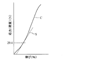
- FIG. 2 is an example of a graph showing a stress-elongation curve of a reinforcing cord.
- the force applied to each cord during filling and loading of the tire is estimated to be 29.4 N
- the tangent line S at the time of 29.4 N stress loading of the stress-elongation curve C at a temperature of 180 ° C. is drawn.
- the slope of the tangent S is calculated as the cord elastic modulus.
- Reinforcing cords can be produced by dipping (DIP) the raw fiber cords.
- DIP dip tension
- the dip tension that is, by dip-treating the fiber cord with a predetermined tension applied thereto, a reinforcing cord having a predetermined rigidity with respect to the fiber stretching direction can be obtained.
- a lyocell fiber cord is applied with a dip tension, for example, increased to a dip tension of 0.13 cN / dtex or more, and then dip-treated to provide a cord of 46.1 cN / dtex (180 ° C., 29.4 N) or more.
- a reinforcing cord having an elastic modulus can be obtained.
- examples of the cellulose fiber include, in addition to rayon and lyocell, a cellulose derivative obtained by chemically esterifying or etherifying cellulose, which is a natural polymer, as a raw material.
- a lyocell fiber that is highly elastic as compared with the rayon fiber and can easily achieve both rigidity and fatigue resistance by twisting.
- the lyocell fiber has high dimensional stability, and therefore has no characteristic shrinkage during production (vulcanization), and the carcass ply has a characteristic that the carcass ply does not easily fall out of the bead.
- Such lyocell fiber is, for example, a cellulosic fiber obtained from a raw material cellulose by a solvent spinning method.
- a solution containing cellulose and a non-solvent such as water dissolved in a solvent is spun into air or a non-precipitating medium, and at that time, it is pulled at a speed higher than the speed at which the fiber-forming solution discharged from the spinneret is sent out. After stretching at a stretching ratio of 3 times or more, it can be obtained by treating with a non-solvent.
- the twist coefficient Nt is preferably 0.5 or more and 0.8 or less. If the twist coefficient is less than 0.5, the fatigue property of the cord may be deteriorated. Further, since the fiber has almost no heat shrinkage rate, the tire uniformity deteriorates, which is not preferable.
- the twisting coefficient is larger than 0.8, the cord strength of the reinforcing cord is reduced, which may lead to a reduction in cutting performance.
- the main cord elastic modulus range cannot be achieved, and it becomes difficult to ensure sufficient steering performance.
- the total fineness of the reinforcing cord is 3500 dtex or more and 5600 dtex or less. This is because if the fineness of the reinforcing cord is less than 3500 dtex, the cord strength of the reinforcing cord is reduced, which may lead to a reduction in cutting performance. On the other hand, when the fineness of the reinforcing cord exceeds 5600 dtex, the gauge becomes thick and unevenness occurs in the sidewall portion 12, which is not preferable.
- the melting cord preferably has a melting point of 300 ° C. or higher.
- the pneumatic tire of the present invention can be a run-flat tire.In this case, since a large amount of heat is generated during run-flat travel, the reinforcing cord has a melting point of less than 300 ° C. This is because the reinforcement cord is melted during the run-flat running, and as a result, the run-flat durability may be lowered.
- the folded end portion of the carcass ply is folded at least to the position of the upper end in the tire radial direction of the bead core 1, and the height h in the tire radial direction of the folded end portion of the carcass ply is the tire radius of the bead core 1. It is preferably 15 mm or less, particularly 10 mm or less from the upper end in the direction.
- the compression input acts on the rim flange portion.
- the tire is basically subject to repeated input to the folded portion due to input in the market, and the carcass cord at the folded portion is strongly reduced, and there is a concern that the carcass cord breaks down. Therefore, the carcass cord is required to be easily reduced in strength by compression input, that is, fatigue. However, it is inevitable that a compression input is applied with the contact point between the rim flange and the tire as a fulcrum during loading.
- the present invention by setting the length of the folded portion of the carcass ply to 15 mm or less, a structure in which no organic fiber is disposed in the portion to which the compression input is applied is applied, and the steering stability is considered without considering the fatigue of the cord This makes it possible to control the tire performance such as property.
- FIG. 3 shows a cross-sectional side view in the width direction of a run flat tire 20 according to another embodiment of the present invention.
- the run flat tire 20 shown in FIG. 3 includes a tread portion 13, a pair of sidewall portions 12 that extend radially inward from the side portions of the tread portion 13, and a bead portion 11 that is continuous with the radially inner end of the sidewall portion 12.
- 1 is the same as that of the tire shown in FIG. 1, and includes a crescent-shaped side reinforcing rubber layer 6 along the inner surface of the carcass, over the entire sidewall region or substantially the entire region, as viewed in the tire width direction cross section. Yes.
- a bead filler 7 is disposed on the outer side in the tire radial direction of each of the ring-shaped bead cores 1 embedded in the bead portion 11, and the outer side in the tire radial direction of the tread portion 13 of the carcass 2.
- a belt composed of two belt layers 3 is disposed in the belt.
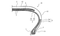
- FIG. 4 shows a cross-sectional side view in the width direction showing another example of the pneumatic tire of the present invention.
- the illustrated pneumatic tire 30 includes a pair of bead portions 11 and sidewall portions 12, and a tread portion 13 connected to the sidewall portions 12, and a pair of bead cores 1 embedded in the pair of bead portions 11.
- the carcass 2 composed of at least one piece extending in a toroidal shape, in the illustrated example, two carcass plies 2a and 2b is used as a skeleton.
- a belt layer composed of two belts 3 a belt reinforcing layer 4 composed of a cap ply covering the entire width of the belt layer, and a tread 5 are sequentially arranged.
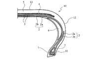
- FIG. 5 is a cross-sectional view in one side in the width direction showing another example of the pneumatic tire of the present invention.
- the pneumatic tire 40 shown in the drawing has a point other than the side reinforcing rubber layer 6 having a crescent-shaped meridional shape over the entire area of the both sidewall portions 12 along the inner surface of the carcass 2.
- 4 is a run-flat tire having the same configuration as the pneumatic tire 30 shown in FIG.
- the arrangement of the belt reinforcing layer 4 is not essential.
- a layer ply that covers only both end portions of the belt layer may be further disposed.
- the belt reinforcing layer 4 may be composed of only layer plies, and the number of each ply is not particularly limited.
- Each of the cap ply and the layer ply is composed of a rubberized layer of a reinforcing cord disposed substantially in the tire circumferential direction.
- the belt layer is usually composed of a rubber layer of a cord that extends at an inclination with respect to the tire equatorial plane, preferably a rubberized layer of at least one steel cord, and in the illustrated example, two belt layers are
- the belt 3 is configured by laminating the cords constituting the belt layer so as to cross each other.
- the bead filler 7 disposed on the outer side in the tire radial direction of the bead core 1 has a triangular section with a height of 15 mm or less, particularly 10 mm or less.
- the carcass cord is repeatedly input to the folded portion by market input, thereby promoting the strength reduction of the folded portion of the carcass cord. Since there is a concern that the cord breaks down, it is required that the strength is not easily lowered by the compression input, that is, the fatigue property is good.
- the bead filler 7 since the bead filler 7 has a small shape, the turned-up portion of the carcass cord immediately follows the inner surface of the tire, so that the contact point between the rim flange and the tire is a fulcrum in the vicinity of the bead portion when loaded.
- the carcass cord exists outside the bending deformation, and only the tensile input, not the compression input, is applied to the cord.
- the tire performance can be controlled. As a result, even in a highly rigid carcass cord, it is possible to enjoy the merit of improving the maneuverability while securing the market durability.
- the height of the bead filler 7 in the present invention means the height of the bead filler 7 in the tire radial direction in a no-load state in which a tire is assembled to an applicable rim and filled with a specified air pressure.
- the applicable rim means a rim defined in the following standard
- the prescribed air pressure means an air pressure defined in accordance with the maximum load capacity in the following standard.
- the standard is an industrial standard effective in an area where tires are produced or used. For example, in the United States, the Tire and Rim Association Inc. In Europe, the European Tire and Rim Technical Organization Standards Manual in Japan, and in Japan, the Japan Automobile Tire Association JATMA Year book.
- the height of the bead filler 7 is set to 15 mm or less because the shape and numerical value of the rim flange are standardized. This is because the code can be avoided. Further, when the height of the bead filler 7 is 15 mm or less, there is a possibility that the compression input is applied to the end of the ply depending on the bending rigidity around the bead, the internal pressure condition, input, and the like. By setting the thickness to 10 mm or less, compression input can be reliably avoided regardless of the type of tire. There is no restriction
- both the conditions relating to the height of the folded end portion of the carcass ply and the conditions relating to the height of the bead filler are satisfied. That is, the folded end portion of the carcass ply is folded at least to the upper end position in the tire radial direction of the bead core, and the height in the tire radial direction of the folded end portion of the carcass ply is 15 mm or less from the upper end portion in the tire radial direction of the bead core. And it is preferable that a bead filler shall have a cross-sectional triangle shape 15 mm or less in height.
- the structure and material of other members constituting the tire are not particularly limited, and a known structure and material can be adopted.
- a tread pattern (not shown) is appropriately formed on the surface of the tread portion 13, and an inner liner (not shown) is formed on the innermost layer.
- an inert gas such as nitrogen can be used as the gas filled in the tire.
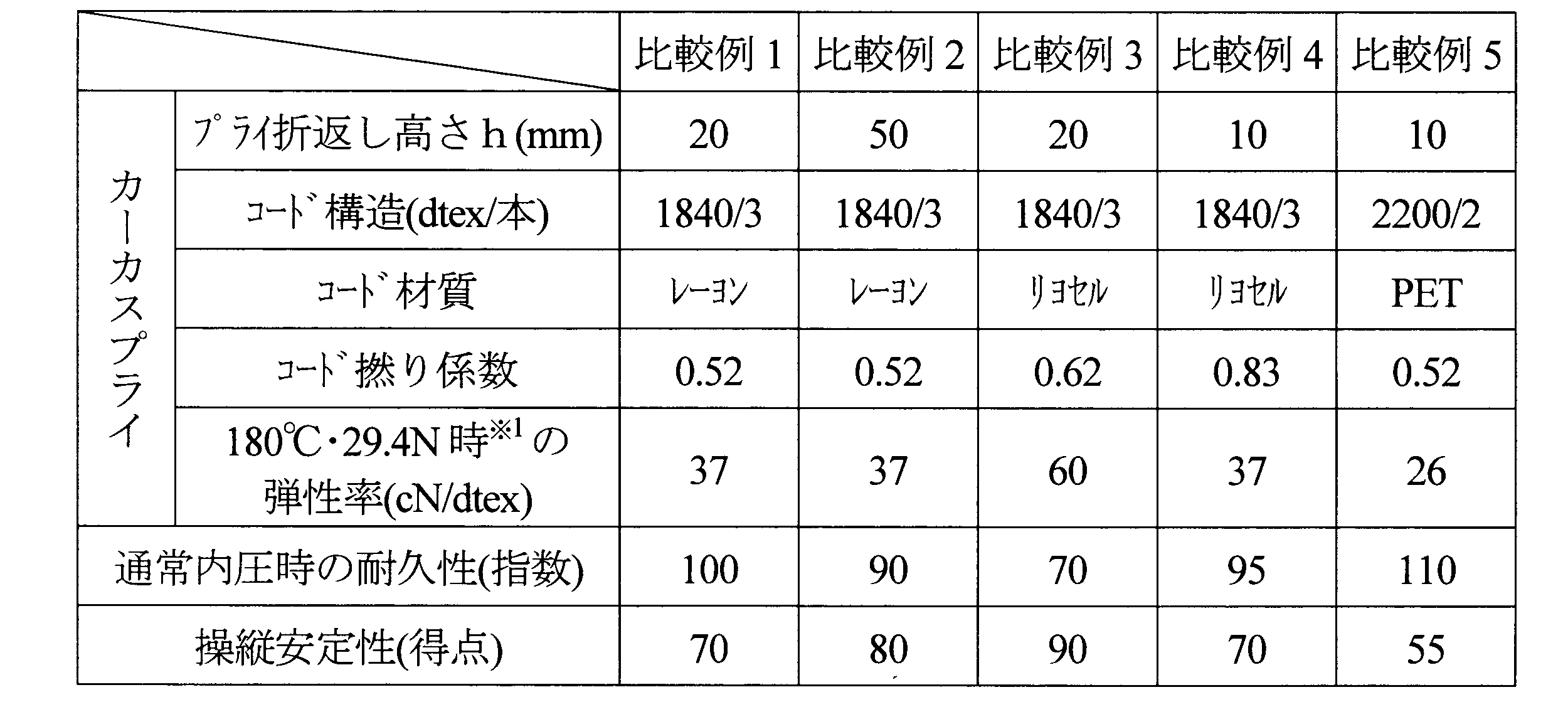
- Examples 1 to 4 and Comparative Examples 1 to 5 A tire of the type shown in FIG. 1 (size 245 / 45R19) was produced.
- Tables 1 and 2 below show the material and structure of the reinforcing cord of the carcass ply, the twist coefficient, and the cord elastic modulus at the time of stress applied with a force of 29.4N per reinforcing cord at a temperature of 180 ° C. is there.
- the fiber cord dip solution used had a formaldehyde / resorcin molar ratio of 1.98, a resorcin / formaldehyde / latex solid mass% of 16.0, and a (NaOH + NH 4 OH) / latex molar ratio of 0.80.
- the covering rubber of the carcass ply was 100 parts by mass of natural rubber, 50 parts by mass of HAF carbon black, and 3 parts by mass of sulfur.
- the number of carcass plies driven into the tire was set to 70/10 cm.
- the elastic modulus at 180 ° C of the reinforcing cord is calculated using the stress-elongation curve of the cord as described above, and the force applied to the cord at the time of filling from the inner pressure of the tire to the load is estimated to be 29.4 N.
- the tangent of the stress-elongation curve at the time was drawn and calculated (see FIG. 2).
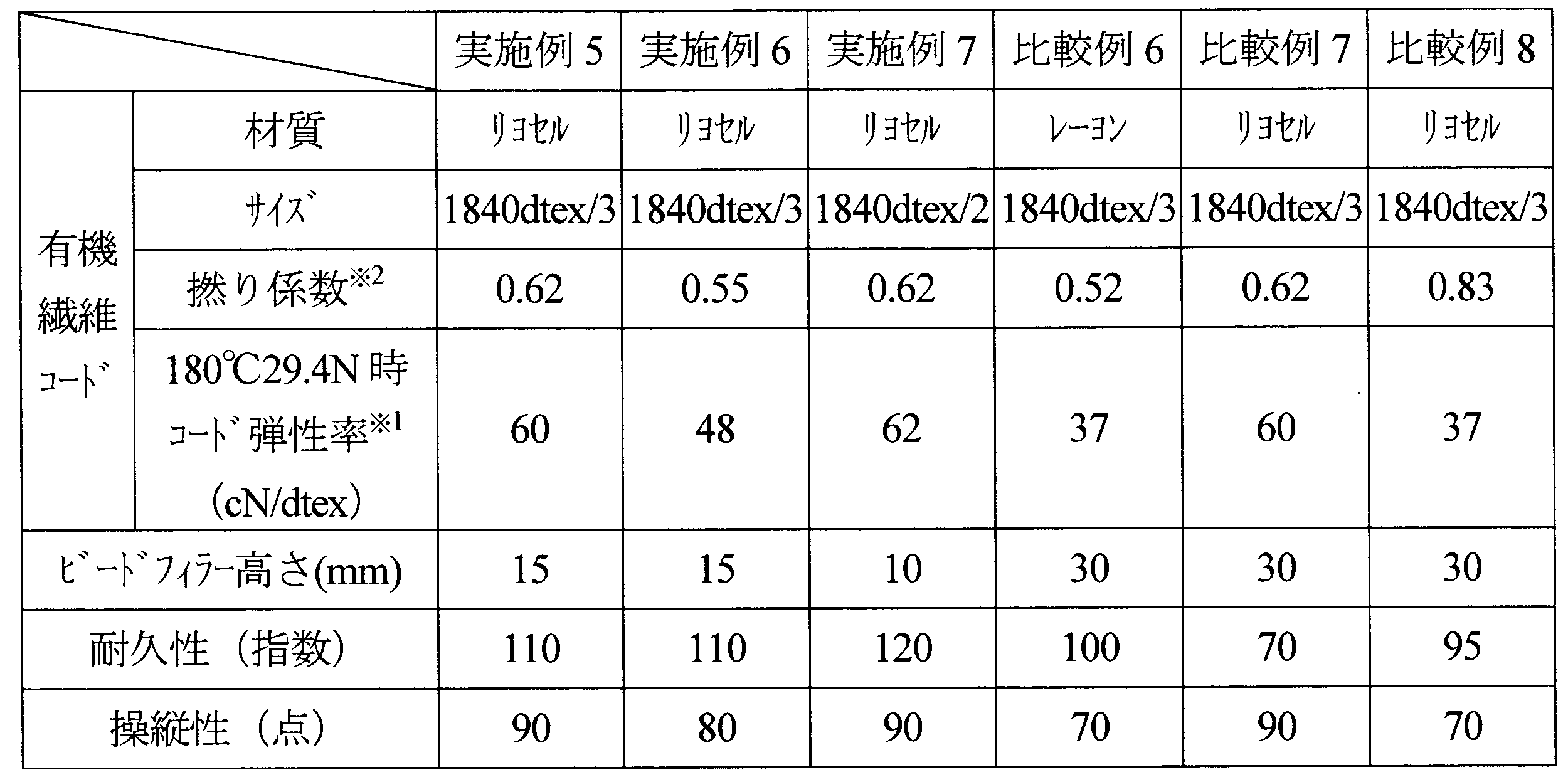
- Examples 5 to 7 and Comparative Examples 6 to 8 As the carcass cord, an organic fiber cord satisfying the conditions shown in the table below is applied, and the height of the bead filler having a triangular cross section is changed as shown in the table below to obtain a tire size 215 / 45R17. Thus, pneumatic radial tires of Examples and Comparative Examples were produced. One carcass ply was used, and the carcass cord was folded around the bead core from the inside of the tire to the outside. Further, the belt layer was made of two layers, and was composed of a rubberized layer of a steel cord extending inclined at an angle of ⁇ 30 ° with respect to the tire equatorial plane.
- Example 2 The dip solution blending, carcass ply coating rubber blending, the number of carcass ply shots and the calculation method of the tensile modulus were the same as in Example 1 above. Each of the obtained test tires was evaluated for durability and maneuverability in accordance with the following.
- N is the number of cord twists (times / 10 cm)
- D is half the total decitex (dtex) of the cord
- ⁇ is the specific gravity of the cord (g / cm 3 )
- a high-rigidity cellulose fiber cord that satisfies the conditions of the present invention is used as a carcass cord, and a specific carcass arrangement, particularly a bead filler structure, is provided.
- a specific carcass arrangement particularly a bead filler structure
Landscapes
- Engineering & Computer Science (AREA)
- Mechanical Engineering (AREA)
- Tires In General (AREA)
Abstract
Description
前記セルロース繊維コードの、温度180℃でのコード1本あたり29.4Nの応力負荷時における引張弾性率が40cN/dtex以上であり、かつ、全てのカーカスコードが、前記一対のビード部にそれぞれ埋設されたビードコアの周りにタイヤ内側から外側に折り返されてなることを特徴とするものである。
Nt=tanθ=0.001×N×√(0.125×D/ρ)
(式中、Nはコードの撚り数(回/10cm)であり、ρはコードの比重(g/cm3)であり、Dはコードの総デシテックス数(dtex)の半分である)で示される撚り係数Ntが、0.5以上0.8以下であることが好ましい。さらに、前記セルロース繊維コードの総繊度は、好適には3500dtex以上5600dtex以下であり、前記カーカスプライの折り返し端部のタイヤ半径方向の高さは、好適には前記ビードコアのタイヤ半径方向上端部から10mm以下である。
図1は、本発明の空気入りタイヤの一例の幅方向片側断面図である。図示するタイヤ10は、トレッド部13と、トレッド部13の側部から半径方向内方へ延びる一対のサイドウォール部12と、サイドウォール部12の半径方向内端に連なるビード部11とからなる。
Nt=tanθ=0.001×N×√(0.125×D/ρ)
(式中、Nはコードの撚り数(回/10cm)であり、ρはコードの比重(g/cm3)であり、Dはコードの総デシテックス数(dtex)の半分である)で表される撚り係数Ntが、0.5以上0.8以下であることが好ましい。撚り係数が0.5未満では、コードの疲労性が悪化してしまうおそれがある。また、熱収縮率がほとんどない繊維であるためタイヤユニフォミティが悪化し、好ましくない。一方、撚り係数が0.8より大きいと、補強コードのコード強力の低下が生じるため、カット性の低下につながるおそれがある。また、低剛性化方向のため主要件のコード弾性率の範囲を達成し得ず、十分な操縦性能を確保することが困難となる。
(実施例1~4および比較例1~5)
図1に示すタイプのタイヤ(サイズ245/45R19)を作製した。カーカスプライの補強コードの材質、構造、撚り係数、並びに180℃の温度にて補強コード1本当たり29.4Nの力を加えた応力時のコード弾性率は下記の表1、2に示すとおりである。繊維コードのディップ液は、ホルムアルデヒド/レゾルシンのモル比が1.98、レゾルシン・ホルムアルデヒド/ラテックス固体質量%が16.0、(NaOH+NH4OH)/ラテックスモル比が0.80のものを使用した。カーカスプライの被覆ゴムは天然ゴム100質量部、HAFカーボンブラック50質量部及び硫黄3質量部とした。タイヤ中へのカーカスプライの打ち込み数は:70本/10cmとした。また、補強コードの180℃における弾性率は、前述したようにコードの応力-伸び曲線を用い、タイヤの内圧充填~荷重時にコード1本当たりにかかる力を29.4Nと見積り、29.4N応力時における応力-伸び曲線の接線を描き、算出した(図2参照)。
ドラム表面が平滑な鋼鉄製で直径が1.707mであるドラム試験機を使用して、周辺温度を30±3℃に制御し、JATMAで定める標準リムサイズのリムを用い、JATMA規格の規定内圧において、JATMA規格の規定負荷能力の荷重をかけて、耐久性ドラム走行試験を行い、タイヤが壊れるまでの距離を測定した。評価は、比較例1の場合を100とした指数で表1、2中に示し、値が大きいほど耐久性が良好である。
JATMAで定める標準リムサイズのリムを用い、JATMA規格の規定内圧を充填した供試タイヤを実車に装着し、ドライバーが操縦性のフィーリング試験を実施し、100を満点とし操縦安定性を採点した。得られた結果を下記の表1、2に示す。

カーカスコードとして、下記の表中に示す条件を満足する有機繊維コードを適用するとともに、断面三角形状のビードフィラーの高さを下記の表中に示すようにそれぞれ変えて、タイヤサイズ215/45R17にて、各実施例および比較例の空気入りラジアルタイヤを作製した。カーカスプライは1枚として、そのカーカスコードがビードコアの周りにタイヤ内側から外側に折り返されてなるものとした。また、ベルト層は2層とし、タイヤ赤道面に対し±30°の角度で傾斜して延びるスチールコードのゴム引き層からなるものとした。ディップ液配合、カーカスプライの被覆ゴム配合、カーカスプライの打ち込み数および引張弾性率の算出方法については、上記実施例1等と同様とした。得られた各供試タイヤにつき、下記に従い耐久性および操縦性を評価した。
各供試タイヤを、ドラム試験機上にて、規定内圧および規定荷重の条件にて80km/hで走行させ、故障が発生するまでの時間を測定した。結果は、比較例6の故障発生までの時間を100とする指数にして示した。数値が大きいほど耐久性が良好である。
各供試タイヤを実車に装着し、ドライバーにより操縦性のフィーリング試験を実施して、100点を満点として操縦性を採点した。点数が高いほど操縦性が良好である。
これらの結果を、下記の表中に併せて示す。
(式中、Nはコードの撚り数(回/10cm)であり、Dはコードの総デシテックスの半分(dtex)であり、ρはコードの比重(g/cm3)である)で定義される撚り係数Ntである。
2 カーカス
2a,2b カーカスプライ
3 ベルト
4 ベルト補強層
5 トレッド
6 サイド補強ゴム層
7 ビードフィラー
10,20,30,40 空気入りラジアルタイヤ
11 ビード部
12 サイドウォール部
13 トレッド部
Claims (10)
- トレッド部と、該トレッド部の側部からタイヤ半径方向内方へ延びる一対のサイドウォール部と、該サイドウォール部のタイヤ半径方向内端に連なるビード部とを、セルロース繊維コードをコーティングゴムで被覆してなる一枚以上のカーカスプライからなるカーカスで補強してなる空気入りタイヤにおいて、
前記セルロース繊維コードの、温度180℃でのコード1本あたり29.4Nの応力負荷時における引張弾性率が40cN/dtex以上であり、かつ、全てのカーカスコードが、前記一対のビード部にそれぞれ埋設されたビードコアの周りにタイヤ内側から外側に折り返されてなることを特徴とする空気入りタイヤ。 - 前記カーカスプライの折り返し端部が、少なくとも前記ビードコアのタイヤ半径方向上端位置まで折り返され、かつ、該カーカスプライの折り返し端部のタイヤ半径方向の高さが、該ビードコアのタイヤ半径方向上端部から15mm以下である請求項1記載の空気入りタイヤ。
- 前記ビードコアのタイヤ半径方向外側に配置されたビードフィラーが、高さ15mm以下の断面三角形状を有する請求項1記載の空気入りタイヤ。
- 前記カーカスプライの折り返し端部が、少なくとも前記ビードコアのタイヤ半径方向上端位置まで折り返され、該カーカスプライの折り返し端部のタイヤ半径方向の高さが、該ビードコアのタイヤ半径方向上端部から15mm以下であり、かつ、該ビードコアのタイヤ半径方向外側に配置されたビードフィラーが、高さ15mm以下の断面三角形状を有する請求項1記載の空気入りタイヤ。
- 前記セルロース繊維コードの、温度180℃でのコード1本あたり29.4Nの応力負荷時における引張弾性率が、100cN/dtex以下である請求項1記載の空気入りタイヤ。
- 前記セルロース繊維コードがリヨセル繊維コードである請求項1記載の空気入りタイヤ。
- 前記セルロース繊維コードの、下記式、
Nt=tanθ=0.001×N×√(0.125×D/ρ)
(式中、Nはコードの撚り数(回/10cm)であり、ρはコードの比重(g/cm3)であり、Dはコードの総デシテックス数(dtex)の半分である)で示される撚り係数Ntが、0.5以上0.8以下である請求項1記載の空気入りタイヤ。 - 前記セルロース繊維コードの総繊度が3500dtex以上5600dtex以下である請求項1記載の空気入りタイヤ。
- 前記カーカスプライの折り返し端部のタイヤ半径方向の高さが、前記ビードコアのタイヤ半径方向上端部から10mm以下である請求項2記載の空気入りタイヤ。
- 前記カーカスの内面に沿って、前記サイドウォール部の全域またはほぼ全域にわたり、タイヤ幅方向断面で見て三日月状のサイド補強ゴム層を備えるランフラットタイヤである請求項1記載の空気入りタイヤ。
Priority Applications (3)
| Application Number | Priority Date | Filing Date | Title |
|---|---|---|---|
| CN201180018868.9A CN102858556B (zh) | 2010-04-15 | 2011-04-15 | 充气轮胎 |
| US13/640,983 US20130025761A1 (en) | 2010-04-15 | 2011-04-15 | Pneumatic tire |
| EP11768965.3A EP2559570B1 (en) | 2010-04-15 | 2011-04-15 | Pneumatic tire |
Applications Claiming Priority (4)
| Application Number | Priority Date | Filing Date | Title |
|---|---|---|---|
| JP2010093715A JP5512369B2 (ja) | 2010-04-15 | 2010-04-15 | 空気入りタイヤ |
| JP2010-093715 | 2010-04-15 | ||
| JP2010-203721 | 2010-09-10 | ||
| JP2010203721A JP2012056519A (ja) | 2010-09-10 | 2010-09-10 | 空気入りラジアルタイヤ |
Publications (1)
| Publication Number | Publication Date |
|---|---|
| WO2011129444A1 true WO2011129444A1 (ja) | 2011-10-20 |
Family
ID=44798812
Family Applications (1)
| Application Number | Title | Priority Date | Filing Date |
|---|---|---|---|
| PCT/JP2011/059425 Ceased WO2011129444A1 (ja) | 2010-04-15 | 2011-04-15 | 空気入りタイヤ |
Country Status (4)
| Country | Link |
|---|---|
| US (1) | US20130025761A1 (ja) |
| EP (1) | EP2559570B1 (ja) |
| CN (1) | CN102858556B (ja) |
| WO (1) | WO2011129444A1 (ja) |
Cited By (3)
| Publication number | Priority date | Publication date | Assignee | Title |
|---|---|---|---|---|
| JP2013199155A (ja) * | 2012-03-23 | 2013-10-03 | Yokohama Rubber Co Ltd:The | 空気入りタイヤ |
| JP2013224054A (ja) * | 2012-04-19 | 2013-10-31 | Bridgestone Corp | ランフラットタイヤ |
| JP2015054680A (ja) * | 2013-09-13 | 2015-03-23 | 東洋ゴム工業株式会社 | 空気入りラジアルタイヤ |
Families Citing this family (6)
| Publication number | Priority date | Publication date | Assignee | Title |
|---|---|---|---|---|
| JP5868303B2 (ja) * | 2012-10-16 | 2016-02-24 | 横浜ゴム株式会社 | 空気入りタイヤ |
| WO2014126701A1 (en) * | 2013-02-15 | 2014-08-21 | Bridgestone Americas Tire Operations, Llc | Tire having an asymmetric body ply construction |
| JP7047703B2 (ja) * | 2018-10-26 | 2022-04-05 | 横浜ゴム株式会社 | 空気入りタイヤ |
| JP7107255B2 (ja) * | 2019-03-07 | 2022-07-27 | 横浜ゴム株式会社 | 空気入りタイヤ |
| JP7028225B2 (ja) * | 2019-08-29 | 2022-03-02 | 横浜ゴム株式会社 | 空気入りタイヤ |
| JP7353902B2 (ja) * | 2019-10-04 | 2023-10-02 | 株式会社ブリヂストン | 空気入りタイヤ |
Citations (8)
| Publication number | Priority date | Publication date | Assignee | Title |
|---|---|---|---|---|
| JPS6028848A (ja) | 1983-07-26 | 1985-02-14 | Soichi Yamaguchi | ナトム工法における粉じん防止用噴霧装置 |
| JPH0781331A (ja) | 1993-09-13 | 1995-03-28 | Bridgestone Corp | 空気入りラジアルタイヤ |
| JPH11504995A (ja) | 1996-03-04 | 1999-05-11 | レンツィング アクチェンゲゼルシャフト | セルロースファイバの製造方法 |
| JP2005199763A (ja) | 2004-01-13 | 2005-07-28 | Bridgestone Corp | 空気入りタイヤ |
| JP2009001073A (ja) * | 2007-06-19 | 2009-01-08 | Yokohama Rubber Co Ltd:The | 空気入りラジアルタイヤ |
| JP2009057008A (ja) * | 2007-09-03 | 2009-03-19 | Sumitomo Rubber Ind Ltd | 自動二輪車用タイヤ |
| JP2010042762A (ja) * | 2008-08-13 | 2010-02-25 | Bridgestone Corp | 空気入りタイヤ |
| JP2010070119A (ja) * | 2008-09-19 | 2010-04-02 | Bridgestone Corp | 空気入りタイヤ |
Family Cites Families (8)
| Publication number | Priority date | Publication date | Assignee | Title |
|---|---|---|---|---|
| JPS638007A (ja) * | 1986-06-24 | 1988-01-13 | ザ グツドイア− タイヤ アンド ラバ− コンパニ− | 空気入りタイヤ |
| JPH0253613A (ja) * | 1988-08-11 | 1990-02-22 | Sumitomo Rubber Ind Ltd | タイヤ |
| JP2913322B2 (ja) * | 1989-09-08 | 1999-06-28 | 横浜ゴム株式会社 | ランフラット空気入りラジアルタイヤ |
| JP3229381B2 (ja) * | 1992-08-27 | 2001-11-19 | 横浜ゴム株式会社 | 空気入りラジアルタイヤ |
| US6230773B1 (en) * | 1998-03-17 | 2001-05-15 | The Goodyear Tire & Rubber Company | Tire with sidewall carcass reinforcement |
| KR100385400B1 (ko) * | 2001-04-11 | 2003-05-23 | 주식회사 효성 | 승용차용 래디얼 타이어 |
| CA2438445C (en) * | 2002-12-26 | 2006-11-28 | Hyosung Corporation | Lyocell multi-filament for tire cord and method of producing the same |
| JP2006076431A (ja) * | 2004-09-09 | 2006-03-23 | Toyo Tire & Rubber Co Ltd | ランフラットタイヤ |
-
2011
- 2011-04-15 WO PCT/JP2011/059425 patent/WO2011129444A1/ja not_active Ceased
- 2011-04-15 CN CN201180018868.9A patent/CN102858556B/zh not_active Expired - Fee Related
- 2011-04-15 US US13/640,983 patent/US20130025761A1/en not_active Abandoned
- 2011-04-15 EP EP11768965.3A patent/EP2559570B1/en not_active Not-in-force
Patent Citations (8)
| Publication number | Priority date | Publication date | Assignee | Title |
|---|---|---|---|---|
| JPS6028848A (ja) | 1983-07-26 | 1985-02-14 | Soichi Yamaguchi | ナトム工法における粉じん防止用噴霧装置 |
| JPH0781331A (ja) | 1993-09-13 | 1995-03-28 | Bridgestone Corp | 空気入りラジアルタイヤ |
| JPH11504995A (ja) | 1996-03-04 | 1999-05-11 | レンツィング アクチェンゲゼルシャフト | セルロースファイバの製造方法 |
| JP2005199763A (ja) | 2004-01-13 | 2005-07-28 | Bridgestone Corp | 空気入りタイヤ |
| JP2009001073A (ja) * | 2007-06-19 | 2009-01-08 | Yokohama Rubber Co Ltd:The | 空気入りラジアルタイヤ |
| JP2009057008A (ja) * | 2007-09-03 | 2009-03-19 | Sumitomo Rubber Ind Ltd | 自動二輪車用タイヤ |
| JP2010042762A (ja) * | 2008-08-13 | 2010-02-25 | Bridgestone Corp | 空気入りタイヤ |
| JP2010070119A (ja) * | 2008-09-19 | 2010-04-02 | Bridgestone Corp | 空気入りタイヤ |
Non-Patent Citations (1)
| Title |
|---|
| See also references of EP2559570A4 * |
Cited By (3)
| Publication number | Priority date | Publication date | Assignee | Title |
|---|---|---|---|---|
| JP2013199155A (ja) * | 2012-03-23 | 2013-10-03 | Yokohama Rubber Co Ltd:The | 空気入りタイヤ |
| JP2013224054A (ja) * | 2012-04-19 | 2013-10-31 | Bridgestone Corp | ランフラットタイヤ |
| JP2015054680A (ja) * | 2013-09-13 | 2015-03-23 | 東洋ゴム工業株式会社 | 空気入りラジアルタイヤ |
Also Published As
| Publication number | Publication date |
|---|---|
| EP2559570A4 (en) | 2015-04-15 |
| US20130025761A1 (en) | 2013-01-31 |
| CN102858556B (zh) | 2016-06-22 |
| CN102858556A (zh) | 2013-01-02 |
| EP2559570A1 (en) | 2013-02-20 |
| EP2559570B1 (en) | 2017-03-08 |
Similar Documents
| Publication | Publication Date | Title |
|---|---|---|
| CN102858556B (zh) | 充气轮胎 | |
| JP4316660B2 (ja) | 空気入りタイヤ | |
| EP1270270B1 (en) | Pneumatic tire | |
| CN102574424B (zh) | 缺气保用轮胎 | |
| JP2001180225A (ja) | ラジアルタイヤ | |
| JP5424474B2 (ja) | ランフラットタイヤ | |
| CN113727866B (zh) | 轮胎 | |
| JP2011218980A (ja) | 空気入りラジアルタイヤ | |
| JP5384255B2 (ja) | 空気入りタイヤ | |
| US20220274445A1 (en) | Pneumatic tire | |
| JP5512369B2 (ja) | 空気入りタイヤ | |
| JP4544961B2 (ja) | ランフラットタイヤ | |
| JP5332422B2 (ja) | 空気入りタイヤ | |
| JP5628525B2 (ja) | 空気入りタイヤ | |
| JP5465587B2 (ja) | ランフラットタイヤ | |
| JP5890114B2 (ja) | 空気入りタイヤ | |
| JP2012171553A (ja) | 空気入りラジアルタイヤ | |
| JPH11301221A (ja) | 空気入りラジアルタイヤ | |
| JP3982902B2 (ja) | 空気入りタイヤ | |
| JP5475366B2 (ja) | ランフラットタイヤ | |
| JP2012056519A (ja) | 空気入りラジアルタイヤ | |
| JP2009120981A (ja) | タイヤ用コード材及びそれを用いた空気入りタイヤの製造方法 | |
| JP2026047147A (ja) | 空気入りタイヤ | |
| JP2026017536A (ja) | 空気入りタイヤ | |
| JP2024121060A (ja) | 空気入りタイヤ |
Legal Events
| Date | Code | Title | Description |
|---|---|---|---|
| WWE | Wipo information: entry into national phase |
Ref document number: 201180018868.9 Country of ref document: CN |
|
| 121 | Ep: the epo has been informed by wipo that ep was designated in this application |
Ref document number: 11768965 Country of ref document: EP Kind code of ref document: A1 |
|
| WWE | Wipo information: entry into national phase |
Ref document number: 13640983 Country of ref document: US |
|
| NENP | Non-entry into the national phase |
Ref country code: DE |
|
| REEP | Request for entry into the european phase |
Ref document number: 2011768965 Country of ref document: EP |
|
| WWE | Wipo information: entry into national phase |
Ref document number: 2011768965 Country of ref document: EP |