WO2011136021A1 - 接触力測定方法及び接触力測定装置 - Google Patents
接触力測定方法及び接触力測定装置 Download PDFInfo
- Publication number
- WO2011136021A1 WO2011136021A1 PCT/JP2011/059140 JP2011059140W WO2011136021A1 WO 2011136021 A1 WO2011136021 A1 WO 2011136021A1 JP 2011059140 W JP2011059140 W JP 2011059140W WO 2011136021 A1 WO2011136021 A1 WO 2011136021A1
- Authority
- WO
- WIPO (PCT)
- Prior art keywords
- marker
- hull
- pantograph
- contact force
- position corresponding
- Prior art date
- Legal status (The legal status is an assumption and is not a legal conclusion. Google has not performed a legal analysis and makes no representation as to the accuracy of the status listed.)
- Ceased
Links
Images





Classifications
-
- G—PHYSICS
- G01—MEASURING; TESTING
- G01L—MEASURING FORCE, STRESS, TORQUE, WORK, MECHANICAL POWER, MECHANICAL EFFICIENCY, OR FLUID PRESSURE
- G01L5/00—Apparatus for, or methods of, measuring force, work, mechanical power, or torque, specially adapted for specific purposes
-
- G—PHYSICS
- G01—MEASURING; TESTING
- G01L—MEASURING FORCE, STRESS, TORQUE, WORK, MECHANICAL POWER, MECHANICAL EFFICIENCY, OR FLUID PRESSURE
- G01L5/00—Apparatus for, or methods of, measuring force, work, mechanical power, or torque, specially adapted for specific purposes
- G01L5/0057—Apparatus for, or methods of, measuring force, work, mechanical power, or torque, specially adapted for specific purposes measuring forces due to spring-shaped elements
-
- B—PERFORMING OPERATIONS; TRANSPORTING
- B60—VEHICLES IN GENERAL
- B60M—POWER SUPPLY LINES, AND DEVICES ALONG RAILS, FOR ELECTRICALLY- PROPELLED VEHICLES
- B60M1/00—Power supply lines for contact with collector on vehicle
- B60M1/12—Trolley lines; Accessories therefor
- B60M1/28—Manufacturing or repairing trolley lines
-
- G—PHYSICS
- G01—MEASURING; TESTING
- G01B—MEASURING LENGTH, THICKNESS OR SIMILAR LINEAR DIMENSIONS; MEASURING ANGLES; MEASURING AREAS; MEASURING IRREGULARITIES OF SURFACES OR CONTOURS
- G01B11/00—Measuring arrangements characterised by the use of optical techniques
-
- G—PHYSICS
- G01—MEASURING; TESTING
- G01L—MEASURING FORCE, STRESS, TORQUE, WORK, MECHANICAL POWER, MECHANICAL EFFICIENCY, OR FLUID PRESSURE
- G01L1/00—Measuring force or stress, in general
- G01L1/04—Measuring force or stress, in general by measuring elastic deformation of gauges, e.g. of springs
- G01L1/044—Measuring force or stress, in general by measuring elastic deformation of gauges, e.g. of springs of leaf springs
-
- B—PERFORMING OPERATIONS; TRANSPORTING
- B60—VEHICLES IN GENERAL
- B60L—PROPULSION OF ELECTRICALLY-PROPELLED VEHICLES; SUPPLYING ELECTRIC POWER FOR AUXILIARY EQUIPMENT OF ELECTRICALLY-PROPELLED VEHICLES; ELECTRODYNAMIC BRAKE SYSTEMS FOR VEHICLES IN GENERAL; MAGNETIC SUSPENSION OR LEVITATION FOR VEHICLES; MONITORING OPERATING VARIABLES OF ELECTRICALLY-PROPELLED VEHICLES; ELECTRIC SAFETY DEVICES FOR ELECTRICALLY-PROPELLED VEHICLES
- B60L5/00—Current collectors for power supply lines of electrically-propelled vehicles
- B60L5/18—Current collectors for power supply lines of electrically-propelled vehicles using bow-type collectors in contact with trolley wire
- B60L5/20—Details of contact bow
Definitions
- the present invention relates to a contact force measuring method and a contact force measuring device.
- the electric railway is supplied with electric power when the pantograph, which is a current collector installed on the roof, comes in contact with the overhead line.
- a force called contact force is generated between the pantograph and the overhead wire.
- the pantograph is separated from the overhead wire, and a discharge phenomenon called an arc occurs between the pantograph and the overhead wire.
- this arc occurs, the overhead wire is worn.
- the contact force is too large, it causes wear of the overhead wire. In other words, it is better that the fluctuation of the contact force is small.
- Patent Document 1 there is a method of obtaining a contact force by measuring in advance a frequency response function of a pantograph with respect to a contact force variation and performing a superposition integration of a time-series response and a frequency response function of the running pantograph. It is disclosed.
- Patent Document 2 discloses a method of obtaining a contact force by installing a sensor such as an accelerometer or a strain gauge on a pantograph and measuring a spring reaction force and an inertial force of the pantograph.
- a sensor such as an accelerometer or a strain gauge
- Patent Document 3 two light sources such as LEDs are installed at the top and bottom of the spring part of the pantograph, the relative displacement is obtained by processing an image obtained by photographing the light source with a CCD camera, and the amount of expansion and contraction of the spring is obtained.
- a method for obtaining a contact force is disclosed.
- Patent Document 4 a line sensor camera (hereinafter referred to as a line sensor) is installed on the roof of a pantograph, the spring part of the pantograph is photographed, the photographed image is processed to obtain a relative displacement, and the amount of expansion and contraction of the spring is determined. A method of obtaining contact force by obtaining is disclosed. Note that Patent Document 4 below does not disclose details of image processing.
- Patent Document 5 a marker in which a region where light is easily reflected and a region where light is not easily reflected is attached to a pantograph, and the marker is photographed vertically by a line sensor installed on the roof of the vehicle.
- a method for measuring the displacement of a pantograph by detecting the position by pattern matching is disclosed.
- Patent Document 5 pattern matching is performed by scanning a marker pattern corresponding to a striped pattern in the height direction every unit time in a spatio-temporal image and searching for a location that matches or approximates a certain level. Thus, it can be clearly separated from the background even in the daytime. In addition, data can be continuously acquired even when the brightness of the background suddenly changes, such as in a tunnel wellhead. In addition, according to the method disclosed in Patent Document 5 below, it is possible to obtain the relative displacement and the amount of expansion and contraction of the spring.
- Patent Document 4 since the method disclosed in Patent Document 4 is a non-contact contact force measurement method using image processing, it is not necessary to perform special work on the pantograph, and is a more general measurement method. In this method, however, the upper and lower portions of the spring need to be displaced in order to obtain the amount of expansion and contraction of the spring, and therefore the markers attached to the upper and lower portions of the spring must be imaged by the line sensor.
- Patent Documents 3 and 4 can be applied without problems when the upper and lower portions of the spring are visible from the outside and are conventional pantographs that can image the upper and lower portions of the spring with a line sensor. it can.
- the pantograph having a structure in which the boat body part and the spring part cannot be directly photographed the upper and lower parts of the spring cannot be visually recognized from the outside, and the upper and lower parts of the spring cannot be imaged by the line sensor.
- the methods disclosed in Patent Documents 3 and 4 have a problem that the contact force cannot be measured in a pantograph having a structure in which the boat body portion and the spring portion cannot be directly photographed.
- the present invention is a contact force measurement method and a contact force measurement method that can measure the contact force of a pantograph by image processing even in a pantograph having a structure that cannot directly photograph the hull part and the spring part.
- An object is to provide an apparatus.
- the contact force measuring method for solving the above-mentioned problem is In the method for measuring the contact force of a pantograph having a structure in which the hull is supported on the hull support via a plurality of springs, Take an image of the pantograph, By combining the plurality of springs and assuming that a composite spring is virtually in the center in the width direction of the pantograph, the position corresponding to the boat body in the center in the width direction of the pantograph and the boat body from the image The relative displacement of the support portion is calculated, and the expansion / contraction amount of the virtual composite spring is calculated by calculating the difference between the relative displacement and the natural length of the virtual composite spring, Multiply the spring constant of the composite spring to find the spring reaction force, From the image, the displacement of the position corresponding to the hull is second-order differentiated to calculate the acceleration, the inertial force is obtained by multiplying the acceleration by the equivalent mass of the pantograph, Obtain the lift acting on the hull from the actual vehicle travel speed data synchronized
- the contact force measuring method according to the second invention for solving the above-mentioned problem is the contact force measuring method according to the first invention,
- One marker is installed at the center in the width direction of the position corresponding to the hull of the pantograph, Two markers in total, one on each side in the width direction of the central marker at a position corresponding to the hull of the pantograph,
- a marker is installed on the hull support, From the image, three markers installed at a position corresponding to the hull and a position of a marker installed on the hull support are detected.
- a contact force measurement method for solving the above-described problems is the contact force measurement method according to the first invention.
- Two markers are installed, one on each side in the width direction of the position corresponding to the hull of the pantograph, A marker is installed on the hull support, An average position of two markers set at a position corresponding to the hull and a position of the marker set on the hull support are detected from the image.
- a contact force measurement method for solving the above-described problem is the contact force measurement method according to the first invention.
- One marker is installed at the center in the width direction of the position corresponding to the hull of the pantograph, One marker is installed on one side in the width direction of the central marker at a position corresponding to the hull of the pantograph, A marker is installed on the hull support, Detecting the position of two markers installed at a position corresponding to the hull and the marker installed on the hull support from the image, From the position of the central marker at a position corresponding to the hull and the position of the marker placed on one side in the width direction of the central marker at a position corresponding to the hull, a virtual marker is obtained by linear prediction. The position is obtained.
- a contact force measuring device for solving the above-described problem is
- the pantograph contact force measuring device having a structure in which the boat body is supported on the boat body support via a plurality of springs, Photographing means for photographing an image of the pantograph;
- Photographing means for photographing an image of the pantograph;
- a contact force measuring device for solving the above problem is the contact force measuring device according to the fifth aspect of the invention, One marker at the center in the width direction of the position corresponding to the hull of the pantograph; A total of two markers, one on each side in the width direction of the central marker at a position corresponding to the hull of the pantograph, A marker is provided on the hull support,
- the contact force calculation means includes From the image, three markers installed at a position corresponding to the hull and a position of a marker installed on the hull support are detected.
- a contact force measuring device for solving the above-mentioned problem is the contact force measuring device according to the fifth aspect of the invention, A total of two markers, one on each side in the width direction of the position corresponding to the hull of the pantograph, A marker is provided on the hull support, The contact force calculation means includes An average position of two markers set at a position corresponding to the hull and a position of the marker set on the hull support are detected from the image.
- a contact force measuring device for solving the above problems is the contact force measuring device according to the fifth aspect of the invention, One marker at the center in the width direction of the position corresponding to the hull of the pantograph; One marker on one side in the width direction of the central marker at a position corresponding to the hull of the pantograph; A marker is provided on the hull support,
- the contact force calculation means includes Detecting the position of two markers installed at a position corresponding to the hull and the marker installed on the hull support from the image, From the position of the central marker at a position corresponding to the hull and the position of the marker placed on one side in the width direction of the central marker at a position corresponding to the hull, a virtual marker is obtained by linear prediction. The position is obtained.
- a contact force measuring method and a contact force measuring device capable of measuring a contact force of a pantograph by image processing even in a pantograph having a structure in which a boat part and a spring part cannot be directly photographed. can do.
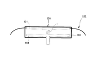
- FIG. 10 is a schematic diagram showing an example of a pantograph that cannot directly photograph the hull part and the spring part.
- the pantograph 100 having a structure in which the hull 101 portion and the spring 102 portion of the pantograph 100 are protected by the cover 103, the upper end of the hull 101 and the upper end of the cover 103 are connected.
- the boat body 101 is also displaced in conjunction with the cover 103.
- the hull support 104 is not directly connected to the cover 103 and has low linkage with the cover 103, it is assumed that the marker is simply pasted on the cover 103 surface where the spring 102 is hidden. However, since the marker is displaced together with the cover 103, the amount of expansion and contraction of the spring 102 cannot be measured.
- the combined spring 1 is virtually in the center in the width direction of the boat body 101 by combining the left and right springs 102. It is considered.
- a central upper marker 2C is attached to the upper part of the center of the cover 103 (a position corresponding to the hull 101), and the left upper part is located on both sides in the width direction of the central upper marker 2C. Attach the marker 2L and the upper marker 2R on the right side. Further, the lower marker 3 is attached to the hull support 104 portion at the lower center portion of the cover 103.
- the relative displacement between the upper portion of the center portion of the cover 103 (position corresponding to the boat body 101) and the center portion of the boat body support 104 is obtained, and the expansion / contraction amount of the virtual composite spring 1 is calculated.
- the relative displacement is a difference between the position of the center upper marker 2C and the position of the lower marker 3 indicated by the arrow D in FIG.
- the amount of expansion / contraction of the virtual synthetic spring 1 can be obtained by obtaining the difference between the displacement (natural length) when the virtual synthetic spring 1 is not expanded and contracted and the relative displacement. Then, the spring reaction force is obtained by multiplying the obtained amount of expansion / contraction of the virtual composite spring 1 by the composite spring constant.
- the pantograph 100 having a structure in which the boat body 101 is supported by the two left and right springs 102 will be described as an example, but the pantograph 100 having a structure in which the boat body 101 is supported by more springs 102 may be used. Similarly, the expansion / contraction amount of the virtual composite spring 1 can be obtained.
- a pantograph having a structure in which the boat body 101 portion and the spring 102 portion cannot be directly photographed is described as an example, but the boat body 101 portion and the spring 102 portion can be directly photographed. It is also possible to apply the contact force measuring method and the contact force measuring apparatus according to the present embodiment to a conventional pantograph having a structure.
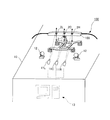
- FIG. 1 is a schematic diagram illustrating a configuration of a contact force measuring apparatus according to the present embodiment.
- three line sensors 11L, 11C, and 11R are installed on a vehicle 10, and an illumination 12 is installed in the vicinity thereof.
- an upper marker 2 ⁇ / b> L, 2 ⁇ / b> C, 2 ⁇ / b> R and a lower marker 3 are made of a white material that easily reflects light on a black material that hardly reflects light on the cover 103 surface portion of the pantograph 100. Mounting, the illumination 12 is applied to the upper markers 2L, 2C, 2R and the lower marker 3.
- the center upper marker 2C and the lower marker 3 are photographed by the center line sensor 11C, the left upper marker 2L is photographed by the left line sensor 11L, and the right upper marker 2R is photographed by the right line sensor 11R. Images taken by the line sensors 11L, 11C, and 11R are stored in the processing PC 13 installed in the vehicle 10.
- the position of the upper marker 2C and the lower marker 3 at the center of the center part of the pantograph 100 is detected by processing the image photographed by the center line sensor 11C.
- the relative displacement is calculated from the positions of the center upper marker 2C and the lower marker 3, and the difference between the relative displacement and the natural length of the virtual combined spring 1 is calculated to calculate the amount of expansion / contraction of the virtual combined spring 1.
- the spring reaction force is obtained by multiplying the expansion / contraction amount of the virtual composite spring 1 by the composite spring constant.
- the images taken by the line sensors 11L, 11C, and 11R are processed by the processing PC 13, thereby detecting the positions of the upper markers 2L, 2C, and 2R of the pantograph 100.
- the acceleration is calculated by second-order differentiation of the displacement of the upper markers 2L, 2C, 2R, and the inertial force is obtained by multiplying this acceleration by the equivalent mass of the pantograph 100.
- the lift Faero is obtained by the following equation (1).
- C L represents the lift coefficient of the hull
- ⁇ represents the air density
- V represents the traveling speed
- S represents the representative area of the hull.
- the traveling speed V is calculated from the actual traveling data of the vehicle 10 that is time-synchronized with the image data. Other parameters can be obtained experimentally.
- the contact force of the pantograph 100 is obtained by adding the spring reaction force, inertial force, and lift obtained by the above method.
- FIG. 2 is a flowchart illustrating a processing procedure in the contact force measurement method according to the present embodiment.
- step P ⁇ b> images taken by the line sensors 11 ⁇ / b> L, 11 ⁇ / b> C, and 11 ⁇ / b> R are stored in the processing PC 13 installed in the vehicle 10.
- step P11 pattern matching is performed using the templates of the upper markers 2L, 2C, 2R and the lower marker 3 acquired in advance by the processing PC 13, so that the saved image is attached to the pantograph 100. The positions of the upper markers 2L, 2C, 2R and the lower marker 3 are detected.
- step P12 the processing PC 13 calculates the relative displacement of the central portion of the pantograph 100, and obtains the difference between the relative displacement and the natural length of the virtual combined spring 1 to determine the virtual combined spring 1's. Calculate the amount of expansion and contraction.
- the spring reaction force is obtained by multiplying the expansion / contraction amount by the spring constant of the virtual composite spring 1.
- step P13 the displacement of the upper markers 2L, 2C, 2R is second-order differentiated by the processing PC 13, and the acceleration is calculated.
- the inertial force is obtained by multiplying this acceleration by the equivalent mass of the pantograph 100.
- step P14 lift is obtained from the traveling speed data of the actual vehicle 10 that is time-synchronized with the image data by the processing PC 13.
- Step P15 the contact force of the pantograph 100 is obtained by adding the spring reaction force, inertial force, and lift obtained in Steps P12 to P14 by the processing PC 13. The above is the processing procedure in the contact force measurement method according to the present embodiment.
- the pantograph 100 can be accurately obtained even in the pantograph 100 having a structure in which the boat body 101 portion and the spring 102 portion cannot be directly photographed.
- the contact force can be measured.
- the images taken by the line sensors 11L, 11C, and 11R are processed to obtain the contact force in a non-contact manner.
- it is not necessary to perform special work such as cable wiring or opening a hole.
- the contact force of the pantograph 100 can be measured with high spatial resolution and temporal resolution by using the line sensors 11L, 11C, and 11R. it can.
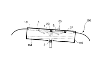
- FIG. 5 is a schematic diagram illustrating the configuration of the contact force measuring apparatus according to the present embodiment.
- the contact force measuring device according to the present embodiment has substantially the same configuration as the contact force measuring device according to the first embodiment, but one of the left and right upper markers 2L and 2R.
- the position of the left upper marker 2L is obtained as a virtual marker position 4 by performing linear prediction from the position of the other right upper marker 2R and the center upper marker 2C, and the contact force of the pantograph 100 is obtained.
- the point of reducing the left line sensor 11L is different from the contact force measuring device according to the first embodiment.
- the contact force measuring device is obtained by deleting one of the left and right line sensors 11L, 11R from the three line sensors 11L, 11C, 11R shown in FIG.
- a case where the left line sensor 11L is deleted will be described as an example.
- the line segment S obtained by connecting the position of the upper marker 2R on the right side and the position of the center upper marker 2C is extended by the marker interval L. This is obtained as a virtual marker position 4 where one marker exists. Thus, even when the left line sensor 11L is deleted, the displacement of the upper three points of the pantograph 100 can be obtained by using the virtual marker position 4.
- FIG. 6 is a flowchart illustrating a processing procedure in the contact force measurement method according to the present embodiment.
- step P ⁇ b> 20 images taken by the line sensors 11 ⁇ / b> C and 11 ⁇ / b> R are stored in the processing PC 13 installed in the vehicle 10.
- step P21 pattern matching is performed using the templates of the upper markers 2C and 2R and the lower marker 3 acquired in advance by the processing PC 13, so that the upper marker attached to the pantograph 100 from the saved image.
- the positions of 2C, 2R and the lower marker 3 are detected.
- step P22 a virtual marker position 4 is obtained by linear prediction after pattern matching by the processing PC 13. This is different from the contact force measurement method according to the first embodiment.
- step P23 the processing PC 13 calculates the relative displacement of the central portion of the pantograph 100, and obtains the difference between this relative displacement and the natural length of the virtual combined spring 1 to determine the virtual combined spring 1's. Calculate the amount of expansion and contraction.
- the spring reaction force is obtained by multiplying the expansion / contraction amount by the spring constant of the virtual composite spring 1.
- step P24 the displacement of the upper marker 2C, 2R and the virtual position 4 of the marker is second-order differentiated by the processing PC 13 to calculate the acceleration.
- the inertial force is obtained by multiplying this acceleration by the equivalent mass of the pantograph 100.
- step P25 the lift is obtained from the traveling speed data of the actual vehicle 10 that is time-synchronized with the image data by the processing PC 13.
- step P26 the contact force of the pantograph 100 is obtained by adding the spring reaction force, the inertial force, and the lift force obtained in step P23 to step P25 by the processing PC 13. The above is the processing procedure in the contact force measurement method according to the present embodiment.
- the upper marker on the right side By obtaining the virtual marker position 4 from the position of 2R and the position of the center upper marker 2C and obtaining the contact force of the pantograph 100, the left line sensor 11L is reduced from the contact force measuring device according to the first embodiment. be able to.
- the left upper marker 2L can be reduced from the contact force measuring device according to the first embodiment, and therefore the left upper portion from the image. Since pattern matching for detecting the position of the marker 2L becomes unnecessary and the number of times of pattern matching can be reduced, the processing can be performed faster than the contact force measurement method according to the first embodiment.
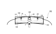
- FIG. 9 is a schematic diagram illustrating an example of deflection of the boat body due to elastic vibration in the contact force measurement device according to the present embodiment.
- the boat body 101 is bent, and from the position of the upper marker 2 ⁇ / b> C in the center of the cover 103, Since the displacement cannot be measured, it is necessary to set the average position 5 of the left upper marker 2L and the right upper marker 2R as the upper position of the synthetic spring 1.
- the contact force measuring apparatus has substantially the same configuration as the contact force measuring apparatus according to the first embodiment, but the average position 5 of the left upper marker 2L and the right upper marker 2R is The relative displacement was calculated from the position of the lower marker 3.
- the case where the center upper marker 2C is installed has been described, but the center upper marker 2C may be omitted.
- FIG. 8 is a schematic diagram illustrating an example of relative displacement in the contact force measuring apparatus according to the present embodiment.
- the upper position of the synthetic spring 1 obtained from the average position 5 of the left upper marker 2L and the right upper marker 2R and the synthetic spring 1 obtained from the position of the lower marker 3 are used.
- the difference in the lower position is obtained as a relative displacement.
- the relative displacement is a difference between the average position 5 of the left upper marker 2L and the right upper marker 2R and the position of the lower marker 3 indicated by an arrow D in FIGS.
- the processing procedure in the contact force measurement method according to the present embodiment is substantially the same as the processing procedure in the contact force measurement method according to the first embodiment, but the contents of the processing in steps P11 to P13 are different.
- step P11 shown in FIG. 2 pattern matching is performed using templates of the left upper marker 2L, the right upper marker 2R, and the lower marker 3 that are acquired in advance by the processing PC 13.
- the positions of the left upper marker 2L, the right upper marker 2R and the lower marker 3 attached to the pantograph 100 are detected from the stored image.
- step P12 the processing PC 13 calculates the relative displacement of the central portion of the pantograph 100 from the average position 5 and the position of the lower marker 3 of the left upper marker 2L and the right upper marker 2R.
- the amount of expansion / contraction of the virtual synthetic spring 1 is calculated by obtaining the difference from the natural length of the synthetic spring 1.
- the spring reaction force is obtained by multiplying the expansion / contraction amount by the spring constant of the virtual composite spring 1.
- Step P13 the displacement of the upper markers 2L and 2R and the displacement of the average position 5 of the left upper marker 2L and the right upper marker 2R are second-order differentiated by the processing PC 13 to calculate the acceleration.
- the inertial force is obtained by multiplying this acceleration by the equivalent mass of the pantograph 100.
- the case where the central upper marker 2C is installed has been described as an example, but the central upper marker 2C may be omitted. Furthermore, when the influence of the elastic vibration of the boat body 101 is negligible, that is, when the boat body 101 is not bent, the contact force measurement method according to the first embodiment is performed, and the elastic vibration of the boat body 101 is reduced. When the vibration frequency range in which the influence is not negligible, that is, when the boat body 101 is bent, the contact force measurement method according to the present embodiment can be implemented.
- the contact force measuring method and the contact force measuring apparatus in the pantograph 100 having a structure in which the boat 101 portion and the spring 102 portion cannot be directly photographed, the elasticity of the boat 101 is obtained. Even when the boat body 101 is bent in a vibration frequency range where the influence of vibration cannot be ignored, the contact force of the pantograph 100 can be measured with high accuracy.
- the present invention relates to a contact force measuring method and a contact force measuring device for measuring a contact force of a pantograph using image processing, and in particular, in a pantograph having a structure in which a boat body part and a spring part cannot be directly photographed, without using a spring expansion / contraction amount.
- the present invention can be used in a contact force measurement method and a contact force measurement device that measure contact force.
Landscapes
- Physics & Mathematics (AREA)
- General Physics & Mathematics (AREA)
- Engineering & Computer Science (AREA)
- Manufacturing & Machinery (AREA)
- Mechanical Engineering (AREA)
- Force Measurement Appropriate To Specific Purposes (AREA)
- Current-Collector Devices For Electrically Propelled Vehicles (AREA)
Abstract
Description
下記特許文献1には、接触力変動に対するパンタグラフの周波数応答関数を予め測定しておいて、走行中のパンタグラフの時系列応答と周波数応答関数との重畳積分を行なうことによって接触力を得る方法が開示されている。
下記特許文献3には、パンタグラフのバネの部分にLEDなどの光源を2個ずつ上下に設置し、CCDカメラで光源を撮影した画像を処理することにより相対変位を求め、バネの伸縮量を求めることで接触力を得る方法が開示されている。
舟体を複数のバネを介して舟体支え上に支持する構造のパンタグラフの接触力測定方法において、
前記パンタグラフの画像を撮影し、
前記複数のバネを合成して前記パンタグラフの幅方向の中央に仮想的に合成バネがあるものとみなして、前記画像より前記パンタグラフの幅方向の中央の前記舟体に相当する位置と前記舟体支え部分の相対変位を計算し、該相対変位と前記仮想的な合成バネの自然長との差を求めることで前記仮想的な合成バネの伸縮量を計算し、該伸縮量に前記仮想的な合成バネのバネ定数を乗じてバネ反力を求め、
前記画像より前記舟体に相当する位置の変位を2階微分して加速度を計算し、該加速度に前記パンタグラフの等価質量を乗じて慣性力を求め、
前記画像と時刻同期させた実際の車両の走行速度データから前記舟体に作用する揚力を求め、
前記バネ反力と前記慣性力と前記揚力を加算して接触力を求める
ことを特徴とする。
前記パンタグラフの前記舟体に相当する位置の幅方向の中央に1つのマーカーを設置し、
前記パンタグラフの前記舟体に相当する位置の前記中央のマーカーの幅方向の両側方にそれぞれ1つ計2つのマーカーを設置し、
前記舟体支えにマーカーを設置し、
前記画像から前記舟体に相当する位置に設置した3つのマーカー及び前記舟体支えに設置したマーカーの位置を検出する
ことを特徴とする。
前記パンタグラフの前記舟体に相当する位置の幅方向の両側方にそれぞれ1つ計2つのマーカーを設置し、
前記舟体支えにマーカーを設置し、
前記画像から前記舟体に相当する位置に設置した2つのマーカーの平均位置及び前記舟体支えに設置したマーカーの位置を検出する
ことを特徴とする。
前記パンタグラフの前記舟体に相当する位置の幅方向の中央に1つのマーカーを設置し、
前記パンタグラフの前記舟体に相当する位置の前記中央のマーカーの幅方向の一方の側方に1つのマーカーを設置し、
前記舟体支えにマーカーを設置し、
前記画像から前記舟体に相当する位置に設置した2つのマーカー及び前記舟体支えに設置したマーカーの位置を検出し、
前記舟体に相当する位置の前記中央のマーカーの位置と、前記舟体に相当する位置の前記中央のマーカーの幅方向の一方の側方に設置したマーカーの位置から、線形予測により仮想のマーカー位置を求める
ことを特徴とする。
舟体を複数のバネを介して舟体支え上に支持する構造のパンタグラフの接触力測定装置において、
前記パンタグラフの画像を撮影する撮影手段と、
前記複数のバネを合成して前記パンタグラフの幅方向の中央に仮想的に合成バネがあるものとみなして、前記画像より前記パンタグラフの幅方向の中央の前記舟体に相当する位置と前記舟体支え部分の相対変位を計算し、該相対変位と前記仮想的な合成バネの自然長との差を求めることで前記仮想的な合成バネの伸縮量を計算し、該伸縮量に前記仮想的な合成バネのバネ定数を乗じてバネ反力を求め、
前記画像より前記舟体に相当する位置の変位を2階微分して加速度を計算し、該加速度に前記パンタグラフの等価質量を乗じて慣性力を求め、
前記画像と時刻同期させた実際の車両の走行速度データから前記パンタグラフに作用する揚力を求め、
前記バネ反力と前記慣性力と前記揚力を加算して接触力を求める接触力計算手段とを備える
ことを特徴とする。
前記パンタグラフの前記舟体に相当する位置の幅方向の中央に1つのマーカーと、
前記パンタグラフの前記舟体に相当する位置の前記中央のマーカーの幅方向の両側方にそれぞれ1つ計2つのマーカーと、
前記舟体支えにマーカーと
を備え、
前記接触力計算手段は、
前記画像から前記舟体に相当する位置に設置した3つのマーカー及び前記舟体支えに設置したマーカーの位置を検出する
ことを特徴とする。
前記パンタグラフの前記舟体に相当する位置の幅方向の両側方にそれぞれ1つ計2つのマーカーと、
前記舟体支えにマーカーと
を備え、
前記接触力計算手段は、
前記画像から前記舟体に相当する位置に設置した2つのマーカーの平均位置及び前記舟体支えに設置したマーカーの位置を検出する
ことを特徴とする。
前記パンタグラフの前記舟体に相当する位置の幅方向の中央に1つのマーカーと、
前記パンタグラフの前記舟体に相当する位置の前記中央のマーカーの幅方向の一方の側方に1つのマーカーと、
前記舟体支えにマーカーと
を備え、
前記接触力計算手段は、
前記画像から前記舟体に相当する位置に設置した2つのマーカー及び前記舟体支えに設置したマーカーの位置を検出し、
前記舟体に相当する位置の前記中央のマーカーの位置と、前記舟体に相当する位置の前記中央のマーカーの幅方向の一方の側方に設置したマーカーの位置から、線形予測により仮想のマーカー位置を求める
ことを特徴とする。
本実施例に係る接触力測定方法及び接触力測定装置においては、舟体部分及びバネ部分を直接撮影することができない構造のパンタグラフにおいても接触力を測定するために、パンタグラフの中央の相対変位と3点の加速度を用いて非接触でパンタグラフの接触力を測定することを特徴としている。
図10に示すように、パンタグラフ100の舟体101部分とバネ102部分がカバー103により保護されている構造のパンタグラフ100では、舟体101上端とカバー103上端は連結されており、カバー103上端に力が加わると舟体101もカバー103と連動して変位するようになっている。
図1に示すように、本実施例に係る接触力測定装置においては、車両10の上にラインセンサ11L,11C,11Rを3台設置し、その付近に照明12を設置する。

最後に、上記の方法で求めたバネ反力と慣性力と揚力を加算することでパンタグラフ100の接触力が求まる。
図2は、本実施例に係る接触力測定方法における処理の手順を示したフローチャートである。
次に、ステップP11において、処理用PC13により予め取得しておいた上部マーカー2L,2C,2R及び下部マーカー3のテンプレートを用いてパターンマッチングを行うことにより、保存した画像からパンタグラフ100に取り付けられた上部マーカー2L,2C,2R及び下部マーカー3の位置を検出する。
最後に、ステップP15において、処理用PC13により上記ステップP12~ステップP14で求めたバネ反力と慣性力と揚力を加算してパンタグラフ100の接触力を求める。
以上が本実施例に係る接触力測定方法における処理の手順である。
図5は、本実施例に係る接触力測定装置の構成を示した模式図である。
図5に示すように、本実施例に係る接触力測定装置は、第1の実施例に係る接触力測定装置とほぼ同様の構成であるが、左右の上部マーカー2L,2Rのうちの一方の左側の上部マーカー2Lの位置を、もう一方の右側の上部マーカー2Rの位置と中央の上部マーカー2Cの位置から線形予測を行って仮想のマーカー位置4として求めて、パンタグラフ100の接触力を求めることにより、左側のラインセンサ11Lを削減する点が、第1の実施例に係る接触力測定装置と異なっている。
図6は、本実施例に係る接触力測定方法における処理の手順を示したフローチャートである。
図6に示すように、はじめに、ステップP20において、ラインセンサ11C,11Rにより撮影した画像を車両10内に設置した処理用PC13に保存する。
最後に、ステップP26において、処理用PC13により上記ステップP23~ステップP25で求めたバネ反力と慣性力と揚力を加算してパンタグラフ100の接触力を求める。
以上が本実施例に係る接触力測定方法における処理の手順である。
図9は、本実施例に係る接触力測定装置における弾性振動による舟体の撓みの例を示した模式図である。
図9に示すように、舟体101の弾性振動の影響が無視できない振動周波数範囲においては、舟体101が撓んでしまい、カバー103の中央の上部マーカー2Cの位置からは、正しく舟体101の変位を測定することができないため、左側の上部マーカー2Lと右側の上部マーカー2Rの平均位置5を合成バネ1の上部の位置とする必要がある。
図8に示すように、本実施例においては、左側の上部マーカー2Lと右側の上部マーカー2Rの平均位置5により求まる合成バネ1の上部の位置と、下部マーカー3の位置により求まる合成バネ1の下部の位置の差を相対変位として求める。ここで、相対変位は、図8、9中に矢印Dで示す左側の上部マーカー2Lと右側の上部マーカー2Rの平均位置5と下部マーカー3の位置との差となる。
本実施例に係る接触力測定方法における処理の手順は、第1の実施例に係る接触力測定方法における処理の手順とほぼ同様であるが、ステップP11~13における処理の内容が異なる。
2L 左側の上部マーカー
2C 中央の上部マーカー
2R 右側の上部マーカー
3 下部マーカー
4 仮想のマーカー位置
5 平均位置
10 車両
11L 左側のラインセンサ
11C 中央のラインセンサ
11R 右側のラインセンサ
12 照明
13 処理用PC
100 パンタグラフ
101 舟体
102 バネ
103 カバー
104 舟体支え
Claims (8)
- 舟体を複数のバネを介して舟体支え上に支持する構造のパンタグラフの接触力測定方法において、
前記パンタグラフの画像を撮影し、
前記複数のバネを合成して前記パンタグラフの幅方向の中央に仮想的に合成バネがあるものとみなして、前記画像より前記パンタグラフの幅方向の中央の前記舟体に相当する位置と前記舟体支え部分の相対変位を計算し、該相対変位と前記仮想的な合成バネの自然長との差を求めることで前記仮想的な合成バネの伸縮量を計算し、該伸縮量に前記仮想的な合成バネのバネ定数を乗じてバネ反力を求め、
前記画像より前記舟体に相当する位置の変位を2階微分して加速度を計算し、該加速度に前記パンタグラフの等価質量を乗じて慣性力を求め、
前記画像と時刻同期させた実際の車両の走行速度データから前記舟体に作用する揚力を求め、
前記バネ反力と前記慣性力と前記揚力を加算して接触力を求める
ことを特徴とする接触力測定方法。 - 前記パンタグラフの前記舟体に相当する位置の幅方向の中央に1つのマーカーを設置し、
前記パンタグラフの前記舟体に相当する位置の前記中央のマーカーの幅方向の両側方にそれぞれ1つ計2つのマーカーを設置し、
前記舟体支えにマーカーを設置し、
前記画像から前記舟体に相当する位置に設置した3つのマーカー及び前記舟体支えに設置したマーカーの位置を検出する
ことを特徴とする請求項1に記載の接触力測定方法。 - 前記パンタグラフの前記舟体に相当する位置の幅方向の両側方にそれぞれ1つ計2つのマーカーを設置し、
前記舟体支えにマーカーを設置し、
前記画像から前記舟体に相当する位置に設置した2つのマーカーの平均位置及び前記舟体支えに設置したマーカーの位置を検出する
ことを特徴とする請求項1に記載の接触力測定方法。 - 前記パンタグラフの前記舟体に相当する位置の幅方向の中央に1つのマーカーを設置し、
前記パンタグラフの前記舟体に相当する位置の前記中央のマーカーの幅方向の一方の側方に1つのマーカーを設置し、
前記舟体支えにマーカーを設置し、
前記画像から前記舟体に相当する位置に設置した2つのマーカー及び前記舟体支えに設置したマーカーの位置を検出し、
前記舟体に相当する位置の前記中央のマーカーの位置と、前記舟体に相当する位置の前記中央のマーカーの幅方向の一方の側方に設置したマーカーの位置から、線形予測により仮想のマーカー位置を求める
ことを特徴とする請求項1に記載の接触力測定方法。 - 舟体を複数のバネを介して舟体支え上に支持する構造のパンタグラフの接触力測定装置において、
前記パンタグラフの画像を撮影する撮影手段と、
前記複数のバネを合成して前記パンタグラフの幅方向の中央に仮想的に合成バネがあるものとみなして、前記画像より前記パンタグラフの幅方向の中央の前記舟体に相当する位置と前記舟体支え部分の相対変位を計算し、該相対変位と前記仮想的な合成バネの自然長との差を求めることで前記仮想的な合成バネの伸縮量を計算し、該伸縮量に前記仮想的な合成バネのバネ定数を乗じてバネ反力を求め、
前記画像より前記舟体に相当する位置の変位を2階微分して加速度を計算し、該加速度に前記パンタグラフの等価質量を乗じて慣性力を求め、
前記画像と時刻同期させた実際の車両の走行速度データから前記パンタグラフに作用する揚力を求め、
前記バネ反力と前記慣性力と前記揚力を加算して接触力を求める接触力計算手段と
を備える
ことを特徴とする接触力測定装置。 - 前記パンタグラフの前記舟体に相当する位置の幅方向の中央に1つのマーカーと、
前記パンタグラフの前記舟体に相当する位置の前記中央のマーカーの幅方向の両側方にそれぞれ1つ計2つのマーカーと、
前記舟体支えにマーカーと
を備え、
前記接触力計算手段は、
前記画像から前記舟体に相当する位置に設置した3つのマーカー及び前記舟体支えに設置したマーカーの位置を検出する
ことを特徴とする請求項5に記載の接触力測定装置。 - 前記パンタグラフの前記舟体に相当する位置の幅方向の両側方にそれぞれ1つ計2つのマーカーと、
前記舟体支えにマーカーと
を備え、
前記接触力計算手段は、
前記画像から前記舟体に相当する位置に設置した2つのマーカーの平均位置及び前記舟体支えに設置したマーカーの位置を検出する
ことを特徴とする請求項5に記載の接触力測定装置。 - 前記パンタグラフの前記舟体に相当する位置の幅方向の中央に1つのマーカーと、
前記パンタグラフの前記舟体に相当する位置の前記中央のマーカーの幅方向の一方の側方に1つのマーカーと、
前記舟体支えにマーカーと
を備え、
前記接触力計算手段は、
前記画像から前記舟体に相当する位置に設置した2つのマーカー及び前記舟体支えに設置したマーカーの位置を検出し、
前記舟体に相当する位置の前記中央のマーカーの位置と、前記舟体に相当する位置の前記中央のマーカーの幅方向の一方の側方に設置したマーカーの位置から、線形予測により仮想のマーカー位置を求める
ことを特徴とする請求項5に記載の接触力測定装置。
Priority Applications (4)
| Application Number | Priority Date | Filing Date | Title |
|---|---|---|---|
| RU2012151269/11A RU2519589C1 (ru) | 2010-04-30 | 2011-04-13 | Способ измерения контактного усилия и устройство измерения контактного усилия |
| EP11774805.3A EP2565612B1 (en) | 2010-04-30 | 2011-04-13 | Contact force measurement method and contact force measurement device |
| KR1020127028352A KR101369581B1 (ko) | 2010-04-30 | 2011-04-13 | 접촉력 측정 방법 및 접촉력 측정 장치 |
| CN201180021692.2A CN102869968B (zh) | 2010-04-30 | 2011-04-13 | 接触力测量方法以及接触力测量装置 |
Applications Claiming Priority (2)
| Application Number | Priority Date | Filing Date | Title |
|---|---|---|---|
| JP2010-104867 | 2010-04-30 | ||
| JP2010104867A JP5443257B2 (ja) | 2010-04-30 | 2010-04-30 | 接触力測定方法及び接触力測定装置 |
Publications (1)
| Publication Number | Publication Date |
|---|---|
| WO2011136021A1 true WO2011136021A1 (ja) | 2011-11-03 |
Family
ID=44861332
Family Applications (1)
| Application Number | Title | Priority Date | Filing Date |
|---|---|---|---|
| PCT/JP2011/059140 Ceased WO2011136021A1 (ja) | 2010-04-30 | 2011-04-13 | 接触力測定方法及び接触力測定装置 |
Country Status (7)
| Country | Link |
|---|---|
| EP (1) | EP2565612B1 (ja) |
| JP (1) | JP5443257B2 (ja) |
| KR (1) | KR101369581B1 (ja) |
| CN (1) | CN102869968B (ja) |
| RU (1) | RU2519589C1 (ja) |
| TW (1) | TWI434778B (ja) |
| WO (1) | WO2011136021A1 (ja) |
Cited By (7)
| Publication number | Priority date | Publication date | Assignee | Title |
|---|---|---|---|---|
| JP2017204930A (ja) * | 2016-05-11 | 2017-11-16 | 公益財団法人鉄道総合技術研究所 | パンタグラフの揚力推定方法及び装置並びにパンタグラフの揚力補償方法及び装置 |
| CN110346076A (zh) * | 2019-07-04 | 2019-10-18 | 中铁第四勘察设计院集团有限公司 | 一种适用于磁浮车辆的侧式受流器试验装置 |
| CN112213008A (zh) * | 2020-09-30 | 2021-01-12 | 成都唐源电气股份有限公司 | 一种非接触式弓网接触力测量方法及装置 |
| CN112484886A (zh) * | 2020-12-10 | 2021-03-12 | 上海地铁维护保障有限公司 | 接触网线岔检测装置 |
| CN112793426A (zh) * | 2021-02-24 | 2021-05-14 | 华东交通大学 | 一种适合双向行驶的减摩抗磨受电弓 |
| CN113820054A (zh) * | 2021-09-22 | 2021-12-21 | 中国科学院力学研究所 | 一种列车刚性弓网接触力全光纤测量方法及系统 |
| CN118225369A (zh) * | 2024-05-27 | 2024-06-21 | 中铁建电气化局集团轨道交通器材有限公司 | 一种整体吊弦冲击载荷的测试装置和测试方法 |
Families Citing this family (18)
| Publication number | Priority date | Publication date | Assignee | Title |
|---|---|---|---|---|
| US9714965B2 (en) * | 2015-01-20 | 2017-07-25 | Aclara Meters, LLC | System for measuring contact force in a utility meter |
| ITUA20162698A1 (it) * | 2016-04-19 | 2017-10-19 | Mer Mec S P A | Sistema ottico per la misura della forza di contatto tra il pantografo e la catenaria |
| CN107487187B (zh) * | 2017-08-25 | 2023-06-30 | 诺和君目(北京)科技有限公司 | 接触压力反馈式受电弓控制系统 |
| CN107560770B (zh) * | 2017-08-28 | 2019-06-25 | 南京拓控信息科技股份有限公司 | 一种受电弓对接触网应力的检测装置 |
| DE102017218056A1 (de) * | 2017-10-10 | 2019-04-11 | Knorr-Bremse Gmbh | Aktive Regelung eines Stromabnehmers |
| CN108253893B (zh) * | 2018-01-23 | 2018-10-12 | 哈尔滨工业大学 | 一种大量程高精度微接触力位移测量装置及其控制方法 |
| JP7008001B2 (ja) * | 2018-08-31 | 2022-01-25 | 株式会社明電舎 | 非接触式パンタグラフ接触力測定装置 |
| CN109443811B (zh) * | 2018-11-19 | 2021-03-26 | 中国科学院力学研究所 | 一种非接触式测量受电弓模态的方法 |
| FR3095167B1 (fr) * | 2019-04-19 | 2021-08-27 | Sncf Reseau | Pantographe équipé d’un système de détection |
| US11548165B2 (en) * | 2019-10-10 | 2023-01-10 | Mitsubishi Electric Research Laboratories, Inc. | Elastomeric tactile sensor |
| US11472040B2 (en) * | 2019-10-10 | 2022-10-18 | Mitsubishi Electric Research Laboratories, Inc. | Tactile sensor |
| CN110806236A (zh) * | 2019-11-20 | 2020-02-18 | 北京市地铁运营有限公司地铁运营技术研发中心 | 一种弓网压力及硬点动态检测装置 |
| CN112229550A (zh) * | 2020-09-30 | 2021-01-15 | 成都唐源电气股份有限公司 | 一种基于双立体靶标的非接触式弓网接触力测量系统 |
| CN112519584A (zh) * | 2020-12-09 | 2021-03-19 | 中铁建电气化局集团南方工程有限公司 | 一种具有自保护装置的受电弓 |
| CN113256723B (zh) * | 2021-06-29 | 2023-03-21 | 西南交通大学 | 一种受电弓升降弓时间及弓头位移曲线自动检测方法 |
| CN113588300B (zh) * | 2021-08-02 | 2023-12-08 | 中车大连机车车辆有限公司 | 一种轨道车辆试验台接触网模拟装置 |
| CN114414116B (zh) * | 2021-12-31 | 2023-08-01 | 成都唐源电气股份有限公司 | 一种基于三轴加速度的弓网接触力分析方法 |
| TWI863361B (zh) * | 2023-06-16 | 2024-11-21 | 國立高雄科技大學 | 微應變位移量測裝置及量測方法 |
Citations (9)
| Publication number | Priority date | Publication date | Assignee | Title |
|---|---|---|---|---|
| JPH11136804A (ja) * | 1997-10-30 | 1999-05-21 | Central Japan Railway Co | パンタグラフの接触力の測定方法 |
| JPH11194059A (ja) | 1997-12-28 | 1999-07-21 | Railway Technical Res Inst | 接触力測定装置 |
| JP2001235310A (ja) | 2000-02-23 | 2001-08-31 | Railway Technical Res Inst | パンタグラフ変位並びに接触力及びトロリ線偏位の測定装置 |
| JP2002328063A (ja) * | 2001-05-01 | 2002-11-15 | East Japan Railway Co | パンタグラフ接触力測定装置 |
| JP2004301591A (ja) | 2003-03-31 | 2004-10-28 | Railway Technical Res Inst | パンタグラフの接触力測定方法及び接触力測定装置 |
| JP2008104312A (ja) | 2006-10-20 | 2008-05-01 | Meidensha Corp | 画像処理によるパンタグラフ測定装置 |
| JP2008185457A (ja) | 2007-01-30 | 2008-08-14 | Railway Technical Res Inst | パンタグラフの接触力測定方法及び接触力測定装置 |
| JP2009244023A (ja) * | 2008-03-31 | 2009-10-22 | Railway Technical Res Inst | ラインセンサを利用した計測装置 |
| JP2010025677A (ja) * | 2008-07-17 | 2010-02-04 | Railway Technical Res Inst | パンタグラフの接触力測定方法及び装置 |
Family Cites Families (6)
| Publication number | Priority date | Publication date | Assignee | Title |
|---|---|---|---|---|
| AT391207B (de) * | 1988-09-09 | 1990-09-10 | Siemens Ag Oesterreich | Einrichtung zur messung des kontaktdruckes an stromabnehmern mit einem drucksensor |
| FR2646381B1 (fr) * | 1989-04-28 | 1991-07-26 | Faiveley Sa | Dispositif pour regler la force d'appui d'un pantographe sur un fil catenaire et procede s'y rapportant |
| US20020149571A1 (en) * | 2001-04-13 | 2002-10-17 | Roberts Jerry B. | Method and apparatus for force-based touch input |
| US6679524B2 (en) * | 2001-11-14 | 2004-01-20 | Delphi Technologies, Inc. | Tension sensing assembly |
| JP5245445B2 (ja) * | 2008-02-15 | 2013-07-24 | 株式会社明電舎 | 渡り線測定装置 |
| CN201392280Y (zh) * | 2009-03-30 | 2010-01-27 | 大庆石油学院 | 圆筒内旋转杆柱碰撞接触测试装置 |
-
2010
- 2010-04-30 JP JP2010104867A patent/JP5443257B2/ja active Active
-
2011
- 2011-04-13 EP EP11774805.3A patent/EP2565612B1/en active Active
- 2011-04-13 CN CN201180021692.2A patent/CN102869968B/zh not_active Expired - Fee Related
- 2011-04-13 RU RU2012151269/11A patent/RU2519589C1/ru active
- 2011-04-13 KR KR1020127028352A patent/KR101369581B1/ko active Active
- 2011-04-13 WO PCT/JP2011/059140 patent/WO2011136021A1/ja not_active Ceased
- 2011-04-29 TW TW100115239A patent/TWI434778B/zh active
Patent Citations (9)
| Publication number | Priority date | Publication date | Assignee | Title |
|---|---|---|---|---|
| JPH11136804A (ja) * | 1997-10-30 | 1999-05-21 | Central Japan Railway Co | パンタグラフの接触力の測定方法 |
| JPH11194059A (ja) | 1997-12-28 | 1999-07-21 | Railway Technical Res Inst | 接触力測定装置 |
| JP2001235310A (ja) | 2000-02-23 | 2001-08-31 | Railway Technical Res Inst | パンタグラフ変位並びに接触力及びトロリ線偏位の測定装置 |
| JP2002328063A (ja) * | 2001-05-01 | 2002-11-15 | East Japan Railway Co | パンタグラフ接触力測定装置 |
| JP2004301591A (ja) | 2003-03-31 | 2004-10-28 | Railway Technical Res Inst | パンタグラフの接触力測定方法及び接触力測定装置 |
| JP2008104312A (ja) | 2006-10-20 | 2008-05-01 | Meidensha Corp | 画像処理によるパンタグラフ測定装置 |
| JP2008185457A (ja) | 2007-01-30 | 2008-08-14 | Railway Technical Res Inst | パンタグラフの接触力測定方法及び接触力測定装置 |
| JP2009244023A (ja) * | 2008-03-31 | 2009-10-22 | Railway Technical Res Inst | ラインセンサを利用した計測装置 |
| JP2010025677A (ja) * | 2008-07-17 | 2010-02-04 | Railway Technical Res Inst | パンタグラフの接触力測定方法及び装置 |
Non-Patent Citations (1)
| Title |
|---|
| See also references of EP2565612A4 * |
Cited By (8)
| Publication number | Priority date | Publication date | Assignee | Title |
|---|---|---|---|---|
| JP2017204930A (ja) * | 2016-05-11 | 2017-11-16 | 公益財団法人鉄道総合技術研究所 | パンタグラフの揚力推定方法及び装置並びにパンタグラフの揚力補償方法及び装置 |
| CN110346076A (zh) * | 2019-07-04 | 2019-10-18 | 中铁第四勘察设计院集团有限公司 | 一种适用于磁浮车辆的侧式受流器试验装置 |
| CN112213008A (zh) * | 2020-09-30 | 2021-01-12 | 成都唐源电气股份有限公司 | 一种非接触式弓网接触力测量方法及装置 |
| CN112484886A (zh) * | 2020-12-10 | 2021-03-12 | 上海地铁维护保障有限公司 | 接触网线岔检测装置 |
| CN112793426A (zh) * | 2021-02-24 | 2021-05-14 | 华东交通大学 | 一种适合双向行驶的减摩抗磨受电弓 |
| CN112793426B (zh) * | 2021-02-24 | 2022-09-02 | 华东交通大学 | 一种适合双向行驶的减摩抗磨受电弓 |
| CN113820054A (zh) * | 2021-09-22 | 2021-12-21 | 中国科学院力学研究所 | 一种列车刚性弓网接触力全光纤测量方法及系统 |
| CN118225369A (zh) * | 2024-05-27 | 2024-06-21 | 中铁建电气化局集团轨道交通器材有限公司 | 一种整体吊弦冲击载荷的测试装置和测试方法 |
Also Published As
| Publication number | Publication date |
|---|---|
| JP5443257B2 (ja) | 2014-03-19 |
| CN102869968B (zh) | 2014-10-01 |
| TWI434778B (zh) | 2014-04-21 |
| JP2011232273A (ja) | 2011-11-17 |
| EP2565612B1 (en) | 2017-01-11 |
| CN102869968A (zh) | 2013-01-09 |
| EP2565612A4 (en) | 2015-12-09 |
| KR101369581B1 (ko) | 2014-03-04 |
| RU2519589C1 (ru) | 2014-06-20 |
| KR20130028922A (ko) | 2013-03-20 |
| TW201202073A (en) | 2012-01-16 |
| EP2565612A1 (en) | 2013-03-06 |
Similar Documents
| Publication | Publication Date | Title |
|---|---|---|
| JP5443257B2 (ja) | 接触力測定方法及び接触力測定装置 | |
| JP3699320B2 (ja) | パンタグラフ変位並びに接触力及びトロリ線偏位の測定装置 | |
| US11009436B2 (en) | Rigidity measurement apparatus and rigidity measurement method | |
| JP4923942B2 (ja) | 画像処理によるパンタグラフ測定装置 | |
| JP6159177B2 (ja) | 架線位置計測装置及び方法 | |
| JP4954732B2 (ja) | パンタグラフの接触力測定方法及び接触力測定装置 | |
| EP3936369B1 (en) | Pantograph displacement measuring device, and trolley-wire hard-spot detection method | |
| CN102292235A (zh) | 接触力测量装置和接触力测量方法 | |
| JP5698285B2 (ja) | 架線位置計測装置及び方法 | |
| CN101680748B (zh) | 通过图像处理来测量架空线的磨损的设备 | |
| JP7008001B2 (ja) | 非接触式パンタグラフ接触力測定装置 | |
| JP6644720B2 (ja) | 電車線金具検出システム及びその検出方法 | |
| JP2010071706A (ja) | 画像処理によるパンタグラフの鉛直加速度測定装置および測定方法 | |
| JP2016065838A (ja) | 線条計測装置及びその方法 | |
| EP2821747B1 (en) | Pantograph measurement method, and pantograph measurement device | |
| JP2020041943A (ja) | パンタグラフの総合計測装置およびパンタグラフ押上げ力推定方法 | |
| JP2015220623A (ja) | 移動体撮像システム | |
| JP2004286500A (ja) | 鉄道車両のパンタグラフ状態測定方法及び装置 | |
| JP2014126482A (ja) | 車両重量測定装置及び車両重量測定方法 | |
| JP7505419B2 (ja) | パンタグラフ変位測定装置及びトロリ線硬点検出方法 | |
| JP7859295B2 (ja) | パンタグラフの加速度測定装置及び測定方法 | |
| JP7310668B2 (ja) | 梯形架線残存高さ測定装置及び梯形架線残存高さ測定方法 | |
| JP2023138303A (ja) | パンタグラフの加速度測定装置及び測定方法 | |
| JP2012189363A (ja) | 物体の変位推定方法並びにパンタグラフの接触力推定方法及び装置 | |
| JP2018159610A (ja) | 寸法測定装置 |
Legal Events
| Date | Code | Title | Description |
|---|---|---|---|
| WWE | Wipo information: entry into national phase |
Ref document number: 201180021692.2 Country of ref document: CN |
|
| 121 | Ep: the epo has been informed by wipo that ep was designated in this application |
Ref document number: 11774805 Country of ref document: EP Kind code of ref document: A1 |
|
| ENP | Entry into the national phase |
Ref document number: 20127028352 Country of ref document: KR Kind code of ref document: A |
|
| REEP | Request for entry into the european phase |
Ref document number: 2011774805 Country of ref document: EP |
|
| WWE | Wipo information: entry into national phase |
Ref document number: 2011774805 Country of ref document: EP |
|
| NENP | Non-entry into the national phase |
Ref country code: DE |
|
| ENP | Entry into the national phase |
Ref document number: 2012151269 Country of ref document: RU Kind code of ref document: A |