WO2011136101A1 - 電動モータ、減速機付モータ、およびサンルーフ駆動装置 - Google Patents
電動モータ、減速機付モータ、およびサンルーフ駆動装置 Download PDFInfo
- Publication number
- WO2011136101A1 WO2011136101A1 PCT/JP2011/059702 JP2011059702W WO2011136101A1 WO 2011136101 A1 WO2011136101 A1 WO 2011136101A1 JP 2011059702 W JP2011059702 W JP 2011059702W WO 2011136101 A1 WO2011136101 A1 WO 2011136101A1
- Authority
- WO
- WIPO (PCT)
- Prior art keywords
- holder
- brush
- motor
- unit
- gear casing
- Prior art date
- Legal status (The legal status is an assumption and is not a legal conclusion. Google has not performed a legal analysis and makes no representation as to the accuracy of the status listed.)
- Ceased
Links
Images







Classifications
-
- H—ELECTRICITY
- H02—GENERATION; CONVERSION OR DISTRIBUTION OF ELECTRIC POWER
- H02K—DYNAMO-ELECTRIC MACHINES
- H02K5/00—Casings; Enclosures; Supports
- H02K5/04—Casings or enclosures characterised by the shape, form or construction thereof
- H02K5/14—Means for supporting or protecting brushes or brush holders
- H02K5/143—Means for supporting or protecting brushes or brush holders for cooperation with commutators
- H02K5/148—Slidably supported brushes
-
- H—ELECTRICITY
- H02—GENERATION; CONVERSION OR DISTRIBUTION OF ELECTRIC POWER
- H02K—DYNAMO-ELECTRIC MACHINES
- H02K11/00—Structural association of dynamo-electric machines with electric components or with devices for shielding, monitoring or protection
- H02K11/02—Structural association of dynamo-electric machines with electric components or with devices for shielding, monitoring or protection for suppression of electromagnetic interference
- H02K11/026—Suppressors associated with brushes, brush holders or their supports
-
- H—ELECTRICITY
- H02—GENERATION; CONVERSION OR DISTRIBUTION OF ELECTRIC POWER
- H02K—DYNAMO-ELECTRIC MACHINES
- H02K5/00—Casings; Enclosures; Supports
- H02K5/04—Casings or enclosures characterised by the shape, form or construction thereof
- H02K5/10—Casings or enclosures characterised by the shape, form or construction thereof with arrangements for protection from ingress, e.g. water or fingers
-
- H—ELECTRICITY
- H02—GENERATION; CONVERSION OR DISTRIBUTION OF ELECTRIC POWER
- H02K—DYNAMO-ELECTRIC MACHINES
- H02K7/00—Arrangements for handling mechanical energy structurally associated with dynamo-electric machines, e.g. structural association with mechanical driving motors or auxiliary dynamo-electric machines
- H02K7/10—Structural association with clutches, brakes, gears, pulleys or mechanical starters
- H02K7/116—Structural association with clutches, brakes, gears, pulleys or mechanical starters with gears
- H02K7/1163—Structural association with clutches, brakes, gears, pulleys or mechanical starters with gears where at least two gears have non-parallel axes without having orbital motion
- H02K7/1166—Structural association with clutches, brakes, gears, pulleys or mechanical starters with gears where at least two gears have non-parallel axes without having orbital motion comprising worm and worm-wheel
Definitions
- the present invention relates to an electric motor, a motor with a speed reducer, and a sunroof driving device using these.
- a motor with a speed reducer in which an electric motor and a gear casing that houses a speed reduction mechanism connected to a rotating shaft of the electric motor are integrated.
- this type of electric motor for example, there is a motor with a brush provided with an armature and a pair of brushes slidably contacting (slidably contacting) the armature commutator.
- the pair of brushes are respectively attached to the gear casing in a form housed in a brush holder.
- Two brush holders are formed of resin, and two brush holders are provided so as to correspond to each brush.
- Each of the pair of brush holders is configured to be detachable from the gear casing (see, for example, Patent Document 1).
- the present invention has been made in view of the above-described circumstances, and can improve the assembly workability of the brush holder and can increase the assembly accuracy of the brush holder, the motor with a reduction gear, and the sunroof.
- a drive device is provided.
- An electric motor that solves the above-described problems is provided with a pair of brushes that are disposed on both sides of an armature and a commutator provided in the armature, and that are slidably contacted with the commutator to supply power And a pair of brush holders for accommodating the pair of brushes so as to be movable back and forth with respect to the commutator, and a holder stay for supporting the brush holder.
- the brush holder and the holder stay are integrally formed of resin, and the holder stay is divided and arranged so as to correspond to each brush holder.
- the holder stay is integrated with each brush holder, the workability of assembling the brush holder can be improved as compared with the conventional case where only the brush holder is assembled to the gear casing. That is, the parts for assembling the brush can be increased without increasing the size of the entire motor.
- the holder stay is configured separately for each brush holder. For this reason, the assembly workability
- by increasing the size of the component it becomes easy to manage the dimensions of the component, and the assembly accuracy of the brush holder can be increased.
- a motor with a reduction gear is the above-described electric motor, a gear casing that is integrally attached to the electric motor, and housed in the gear casing and connected to a rotating shaft of the electric motor.
- a reduction mechanism is formed in the gear casing, and the holder stay and the brush holder are attached to the storage recess. Furthermore, a labyrinth portion is provided between the peripheral edge of the storage recess and the portion corresponding to the peripheral edge of the holder stay.
- an electromagnetic shield for suppressing the influence of electromagnetic noise may be provided outside each holder stay.
- the electromagnetic shield is attached to each holder stay, and the holder stay, the brush holder, and the electromagnetic shield are integrated with the holder stay, the brush holder, and the electromagnetic shield on the gear casing. It may be attached.
- the brush, the brush holder, the holder stay, and the electromagnetic shield can be assembled to the gear casing in an integrated state. For this reason, assembly workability
- operativity can be improved further.
- the electromagnetic shield is divided and arranged so as to correspond to each holder stay, and each electromagnetic shield is attached to the gear casing by a fastening means for attaching the electric motor and the gear casing. It may be.
- the electromagnetic shield can be attached to the gear casing at the same time, and the assembling work is facilitated. Furthermore, since each electromagnetic shield and the yoke housing of the electric motor are electrically connected via the fastening means, it is possible to suppress electromagnetic noise generated from the electric motor.
- a sunroof driving device is provided with the above-described motor with a reduction gear on a roof of a vehicle, and a sunroof driving for driving a roof panel provided on the roof using the motor with a reduction gear.
- the motor with a speed reducer is disposed with the electromagnetic shield facing the roof side.
- This configuration makes it possible to prevent the influence of electromagnetic noise on the antenna and the like installed on the vehicle roof. For this reason, a highly reliable sunroof drive device can be provided.
- the assembling workability of the brush holder can be improved as compared with the case where only the brush holder is assembled to the gear casing. That is, the parts assembled to the gear casing can be increased without increasing the size of the entire motor.
- each holder stay is configured separately corresponding to the brush holder. For this reason, the assembly workability
- by increasing the size of the component it becomes easy to manage the dimensions of the component, and the assembly accuracy of the brush holder can be increased.
- FIG. 1 It is a schematic structure figure of a sunroof drive device in a first embodiment of the present invention. It is a perspective view of the motor with a reduction gear in 1st embodiment of this invention. It is a disassembled perspective view of the motor with a reduction gear in 1st embodiment of this invention. It is a disassembled perspective view of the brush unit in 1st embodiment of this invention. It is a longitudinal cross-sectional view of the 1st unit which comprises the brush unit in 1st embodiment of this invention. It is a perspective view of the holder stay in 1st embodiment of this invention. It is a graph which shows the change of the electromagnetic noise in 1st embodiment of this invention, Comprising: The case where a choke coil is wound toward the left direction is shown.
- FIG. 1 is a schematic configuration diagram of a sunroof driving device 500.
- a sunroof driving device 500 is attached to a roof 502 of a vehicle 501 and drives a roof panel 503 provided on the roof 502.
- the sunroof driving device 500 includes a motor 1 with a speed reducer.
- An opening 502a is formed in the roof 502, and a roof panel 503 is provided so that the opening 502a can be opened and closed.
- One end of the cables 504a and 504b is connected to the roof panel 503.
- the other ends of the cables 504a and 504b are connected to a motor 1 with a speed reducer, and the roof panel 503 opens and closes the opening 502a when the motor 1 with a speed reducer is driven.
- the motor 1 with a reduction gear is disposed between the opening 502 a of the roof 502 and the windshield 505.
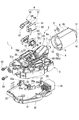
- FIG. 2 is a perspective view of the motor 1 with a speed reducer.
- FIG. 3 is an exploded perspective view of the motor 1 with a speed reducer.
- the motor 1 with a speed reducer includes an electric motor 2 and a gear casing 3 in which the speed reduction mechanism 20 is housed, and a brush unit 4 is attached to the gear casing 3.
- the speed reduction mechanism 20 includes a worm shaft to which power of the electric motor 2 is transmitted, a worm wheel (not shown) that meshes with the worm shaft, and an output shaft 20a connected to the worm wheel.
- the other ends of the cables 504a and 504b are connected to the output shaft 20a.
- the gear casing 3 that houses the speed reduction mechanism 20 is made of resin and can be divided into an upper case 31 and a lower case 32, and is configured so that the speed reduction mechanism 20 can be housed in the upper case 31. ing.
- the motor 1 with a reduction gear is attached to the passenger compartment side of the roof 502 with the upper case 31 facing the roof 502 and the output shaft 20a facing the roof 502.
- the lower case 32 houses a circuit board 33 for driving the electric motor 2.
- a female terminal 35 a that can be connected to the brush unit 4 is mounted on the circuit board 33.
- the lower case 32 is provided with a connector portion 34 to which an external connector (not shown) can be connected.
- the connector part 34 and the circuit board 33 are electrically connected to each other.
- the upper case 31 is formed with an electric motor storage portion 36 capable of storing a part of the electric motor 2 at a location where the electric motor 2 is attached.
- An outer flange portion 37 for attaching the electric motor 2 is integrally formed on the outer peripheral portion of the electric motor housing portion 36.
- the brush unit 4 is attached to the upper case 31 on the side opposite to the electric motor 2 with the outer flange portion 37 interposed therebetween.
- the electric motor 2 is a so-called brush motor that supplies power using the brush 5.
- the electric motor 2 includes a cylindrical yoke housing 6 having an opening 6a and a bottom wall 6b, and an armature 7 that is rotatably provided in the yoke housing 6.
- the yoke housing 6 is attached to the gear casing 3 with the opening 6a facing the gear casing 3 side.
- Two slits 9 into which nuts 8 can be inserted are formed in a portion near the opening 6 a of the peripheral wall 6 b of the yoke housing 6.
- the outer flange portion 37 of the gear casing 3 is formed with an insertion hole 27 into which a bolt 10 as a fastening means can be inserted at a portion corresponding to the nut 8 inserted into the slit 9 of the yoke housing 6.
- the yoke 10 is fastened and fixed to the gear casing 3 by inserting the bolt 10 into the insertion hole 27 and screwing the bolt 10 into the nut 8.
- a permanent magnet 13 is provided on the inner surface of the peripheral wall 6 b of the yoke housing 6.
- the bottom wall 6 c of the yoke housing 6 is provided with a bearing portion 12 for rotatably supporting one end of the rotating shaft 11 of the armature 7.
- the bearing portion 12 projects from the bottom wall 6 c toward the outside of the yoke housing 6 in the axial direction of the rotating shaft 11.
- the armature 7 includes a rotating shaft 11, an armature core 14, and a commutator 15.
- the armature core 14 is fitted and fixed to a portion corresponding to the permanent magnet 13 on the outer peripheral portion of the rotating shaft 11.
- the commutator 15 is fitted and fixed to a portion near the gear casing 3 on the outer peripheral portion of the rotating shaft 11.
- a winding 16 is wound around and mounted on the armature core 14, and a terminal portion of the winding 16 is connected to the commutator 15.
- the commutator 15 is formed in a columnar shape, and is disposed facing the inner wall of the electric motor storage portion 36 of the gear casing 3.
- the commutator 15 is provided with a plurality of unillustrated segments formed side by side on the outer peripheral surface. The end portions of the windings 16 are connected to these segments.
- the pair of brushes 5 and 5 constituting the brush unit 4 disposed on both sides of the commutator 15 are in sliding contact with the commutator 15.
- FIG. 4 is an exploded perspective view of the brush unit 4.
- FIG. 5 is a longitudinal sectional view of the first unit 41 constituting the brush unit 4.
- the brush unit 4 includes two units 41 and 42, a first unit 41 and a second unit 42, so as to correspond to the pair of brushes 5 and 5.
- the basic configurations of the two units 41 and 42 are the same, and each component is formed substantially symmetrically with respect to the commutator 15. For this reason, in the following description, only the 1st unit 41 is demonstrated in detail. For the second unit 42, only a portion having a different shape from the first unit 41 will be described, and the same configuration as the first unit 41 will be denoted by the same reference numeral as the first unit 41 and description thereof will be omitted.
- the first unit 41 is detachably provided on an upper surface 31a on the side opposite to the lower case 32 of the upper case 31 constituting the gear casing 3 (the upper side in FIGS. 3 to 5 and hereinafter simply referred to as the upper side).
- the outer surface side of the first unit 41 is covered with a GND terminal 61a. That is, the GND terminal 61 a is provided on the side where the output shaft 20 a of the speed reduction mechanism 20 is disposed with respect to the upper case 3.
- the motor 1 with a reduction gear is arrange
- the first unit 41 has a holder stay 44a in which a brush holder 43 for housing the brush 5 is integrally formed.
- the second unit 42 also has a similar holder stay 44b. That is, in the present embodiment, the holder stays 44a and 44b are divided and arranged so as to correspond to the brush holders 43 of the first unit 41 and the second unit.
- the brush 5 is for supplying a current to the winding 16 via the commutator 15 and has a quadrangular cross-sectional shape.
- One end of the pigtail 50 is connected to the base end side of the brush 5.
- the brush holder 43 is made of resin.
- the brush holder 43 is formed in a rectangular tube shape so as to correspond to the cross-sectional shape of the brush 5, and has openings 443 as small openings at both ends.
- the brush 5 is accommodated in the brush holder 43 so as to be movable back and forth with respect to the commutator 15. That is, the pair of brush holders 43 are formed with openings 443 at both ends of the brush 5 in the advancing / retreating direction, and accommodates the pair of brushes 5 so as to be able to advance / retreat.
- the brush holder 43 is accommodated in the gear casing 3 when the brush unit 4 is attached to the gear casing 3.
- the gear casing 3 is formed with a recess (storage recess) 38 into which the first unit 41 and the second unit 42 can be inserted from the outside.
- a storage portion 38 a that can store the brush holder 43 is formed in a portion of the recess 38 corresponding to the brush holder 43.
- the storage portion 38 a has an opening (not shown) at a portion corresponding to the brush 5.
- the tip of the brush 5 is in sliding contact with a segment (not shown) of the commutator 15 through this opening.
- FIG. 6 is a perspective view of the holder stay 44a.
- the holder stay 44a is formed of resin and is integrally formed on the upper surface 43a of the brush holder 43 so as to be disposed on the outer surface of the gear casing 3.
- the holder stay 44 a is formed so as to protrude from the brush holder 43 toward the second unit 42 side (left side in FIG. 4) along the recess 38 of the upper case 31.
- a box-shaped element storage portion 45 having an opening 445 as a large opening on the outside is formed at a portion protruding toward the second unit 42 side.
- the element storage portion 45 is formed by integrally forming a storage portion main body 40a for storing the choke coil 46 and the capacitor 47 as noise preventing elements and a pigtail storage portion 40b for storing the pigtail 50 of the brush 5.
- the storage unit main body 40a and the pigtail storage unit 40b communicate with each other.
- a male terminal 49 is provided on the bottom wall 45a of the storage unit main body 40a in the vicinity of the pigtail storage unit 40b.
- the male terminal 49 is formed so as to extend from the bottom wall 45a along the attaching / detaching direction of the first unit 41 (vertical direction in FIGS. 4 and 5).
- the male terminal 49 is connected to the female terminal 35 a of the circuit board 33 housed in the lower case 32 with the first unit 41 attached to the upper case 31.
- the choke coil 46 is housed in the element housing portion 45 at a position near the second unit 42. One end of the choke coil 46 is connected to the other end of the pigtail 50.
- the choke coil 46 is wound around the mandrel 48. The direction in which the choke coil 46 is wound is far from one end side of the choke coil 46, that is, from one end side of the mandrel 48 (end portion close to the pigtail storage portion 40b in FIG. 6) to the other end side (pigtail storage portion 40b in FIG. 6). It is set in the counterclockwise direction (see arrow Y1 in FIG. 6) toward the end.
- the other end of the choke coil 46 is connected to the male terminal 49.
- current is supplied to the brush 5 via the female terminal 35 a of the circuit board 33, the male terminal 49 of the first unit 41, the choke coil 46, and the pigtail 50.
- a capacitor 47 is connected to the male terminal 49.
- the capacitor 47 is housed on the side opposite to the second unit 42 in the element housing 45 (the right side in FIGS. 4 and 6), that is, outside the choke coil 46. Further, the other end of the capacitor 47 is connected to the GND terminal 61a.
- the choke coil 46 is connected in series on the power supply line between the brush 5 and the male terminal 49.
- a capacitor 47 is provided in parallel with the choke coil 46.
- the cover 51a is configured by integrally forming a cover main body 52 and a spring stopper 53.
- the cover main body 52 closes the opening of the storage portion main body 40a of the holder stay 44a and the opening 445 of the element storage portion 45, which is a partial opening of the pigtail storage portion 40b.
- the spring stopper 53 closes a part of the opening of the pigtail storage part 40 b and the opening 443 on the base end side of the brush holder 43.
- a claw portion 53a that is bent and extends so as to wrap around the lower surface 43b of the brush holder 43 is formed.
- the cover 51a is attached to the holder stay 44a by sandwiching and holding the brush holder 43 and the holder stay 44a by the claw portion 53a and the cover body 52.
- the spring stopper 53 is housed in a housing portion 38a formed in the recess 38 of the gear casing 3 together with a part of the brush holder 43 and the holder stay 44a.
- the brush spring 43 accommodates the coil spring 21 that urges the brush 5 toward the commutator 15.
- the cover 51a is attached to the brush holder 43, one end of the coil spring 21 is supported by the spring stopper 53 of the cover 51a. Thereby, the other end of the coil spring 21 reliably biases the brush 5 toward the commutator 15.
- a flange portion 54 having an L-shaped cross section is formed so as to extend toward the electric motor 2 side. .
- the flange portion 54 is formed so as to surround the periphery of the outer flange portion 37 of the gear casing 3.
- a convex portion 55 is formed on the peripheral edge of the outer flange portion 37 so as to face the inside of the flange portion 54.
- the convex portion 55 is continuously formed along the peripheral edge of the outer flange portion 37.
- the convex portion 55 of the present embodiment is formed in an arc shape along the peripheral edge of the arc-shaped outer flange portion 37.
- the side edge 52 b on the spring stopper 53 side of the cover body 52 is outside the peripheral edge of the recess 38 of the gear casing 3, that is, on the opposite side to the second unit 42. It is formed so as to protrude.
- the labyrinth portions 56a and 56b are formed in the gap between the cover main body 52 and the gear casing 3 by the side edge 52b of the cover main body 52, the peripheral edge of the recess 38 of the gear casing 3, and the GND terminal 61a.
- the periphery of the cover main body 52 is disposed between the recess 38 and the periphery of the holder stay 44a. That is, the labyrinth portions 56 a and 56 b are provided between the periphery of the recess 38 and the periphery of the holder stay 44 a corresponding to the periphery of the recess 38.
- a notch 58 is formed in a side wall 57 on the side opposite to the outer flange 37 of the gear casing 3 (left side in FIG. 5).
- the notch 58 is integrated with a later-described protrusion 65 formed in the GND terminal 61a, so that the holder stay 44a and the GND terminal 61a are integrated.
- the GND terminal 61a is formed by, for example, pressing a metal plate made of brass or the like.
- the GND terminal 61a includes a terminal main body 62 that covers the cover main body 52 of the cover 51a from the outside, and a peripheral edge of the terminal main body 62 toward the lower case 32 side (the lower side in FIGS. It is formed by integrally molding the extending GND terminal 63.
- a Y terminal portion 64 is integrally formed at a portion corresponding to the insertion hole 27 on the outer flange portion 37 side of the gear casing 3 in the terminal body 62. That is, the GND terminals 61a and 61b of the two units 41 and 42 are in a state in which the Y terminal portions 64 are opposed to each other.
- the Y terminal portion 64 is fastened by the bolt 10 and the nut 8 together with the outer flange portion 37 of the gear casing 3 and the yoke housing 6 of the electric motor 2. Thereby, the GND terminal 61a is fastened and fixed to the gear casing 3, and the movement of the holder stay 44a in the removal direction is restricted by the GND terminal 61a.
- the Y terminal portion 64 is connected to the Y terminal portion 64 formed on the GND terminal 61 b of the second unit 42 via the bolt 10 for fastening and fixing the gear casing 3 and the yoke housing 6, and the yoke housing 6. And electrically connected. That is, the GND terminals 61a and 61b have a structure in which a GND terminal which has been conventionally integrated is divided so as to correspond to the pair of brushes 5 and 5. In a state where the Y terminal portion 64 of the first unit 41 and the Y terminal portion 64 of the second unit 42 are respectively attached to the gear casing 3, a gap S is formed between the Y terminal portions 64 and 64 as shown in FIG. Is formed.
- the terminal main body 62 is formed with a convex portion 65 on the side wall 66 that overlaps the side wall 57 of the holder stay 44a so as to protrude toward the side wall 57 of the holder stay 44a.
- the convex portion 65 is disposed at a position corresponding to the cutout portion 58 formed in the holder stay 44 a and engages with the cutout portion 58.
- the holder stay 44a, the cover 51a, and the GND terminal 61a are integrated.
- the side edge 62a of the terminal body 62 opposite to the second unit 42 is formed to extend downward from the side edge 52b so as to cover the side edge 52b of the cover body 52. .
- This extended portion constitutes a part of the labyrinth portion 56b.
- the GND terminal 63 of the GND terminal 61 a extends through the upper case 31 to reach the circuit board 33 accommodated in the lower case 32.
- a female terminal 35 b that can be connected to the GND terminal 63 is mounted on the circuit board 33. By connecting the GND terminal 63 to the female terminal 35b, the GND terminals 61a and 61b are grounded to the GND.
- the holder stay 44a of the first unit 41 is provided with the male terminal 49 standing in the vicinity of the pigtail storage part 40b on the bottom wall 45a of the storage part body 40a.
- the holder stay 44b of the second unit 42 is provided with the male terminal 49 standing on the opposite side of the bottom wall 45a of the storage unit body 40a from the pigtail storage unit 40b.
- the GND terminal 61a of the first unit 41 is provided with the GND terminal 63
- the GND terminal 61b of the second unit 42 is not provided with the GND terminal 63. This is because the GND terminal 61 a of the first unit 41 and the GND terminal 61 b of the second unit 42 are electrically connected to each other via the bolt 10.
- a tongue-like portion 67 is formed on the side opposite to the Y terminal portion 64 of the terminal main body 62 so as to bend downward instead of the GND terminal 63.
- the upper case 31 of the gear casing 3 is formed with a slit 29 at a portion corresponding to the tongue-shaped portion 67. The tongue-shaped portion 67 is inserted into the slit 29, thereby preventing the GND terminal 61b of the second unit 42 from rattling.
- the first unit 41 and the second unit 42 constituting the brush unit 4 have the same assembling method with respect to the gear casing 3. Therefore, in the following description, only the assembly method of the first unit 41 will be described, and the description of the assembly method of the second unit 42 will be omitted.
- the male terminal 49 is assembled to the holder stay 44a.
- the other end of the pigtail 50 is connected to one end of the choke coil 46 by spot welding or the like. Thereafter, the choke coil 46 is accommodated in the element accommodating portion 45 and the brush 5 is accommodated in the brush holder 43.
- the capacitor 47 is stored in the element storage unit 45.
- the coil spring 21 is accommodated from the base end side of the brush 5 of the brush holder 43 (rearward in the direction in which the brush 5 is urged).
- the cover 51a is attached to the holder stay 44a.
- the other end of the choke coil 46 and one end of the capacitor 47 are connected to the male terminal 49 by soldering or the like.
- the GND terminal 61a is attached from above the cover 51a.
- the convex portion 65 of the GND terminal 61a engages with the cutout portion 58 of the holder stay 44a.
- the other end of the capacitor 47 is connected to the GND terminal 61a by spot welding or the like. Thereby, the assembly of the first unit 41 is completed.
- the first unit 41 and the second unit 42 are attached to the recess 38 of the gear casing 3.
- the units 41 and 42 are assembled from above the upper case 31 with the brush holders 43 and 43 of the units 41 and 42 facing the concave portion 38.
- tip of the brush 5 is pressed using a jig
- the jig is removed while inserting the brush holders 43, 43 into the storage portion 38 a of the recess 38.
- the first unit 41 and the second unit 42 can be separately assembled to the gear casing 3. For this reason, each unit 41 and 42 can be assembled
- the units 41 and 42 are integrally formed, if an error occurs between the distance between the brush holders 43 and 43 and the distance between the storage portions 38a and 38a of the gear casing 3, the units 41 and 42 Assembling becomes difficult.
- the first unit 41 and the second unit 42 are separately assembled to the gear casing 3.
- the Y terminal portion 64 of the first unit 41 and the Y terminal portion 64 of the second unit 42 attached to the gear casing 3, respectively, a gap S between the Y terminal portions 64 and 64 as shown in FIG. Is formed. For this reason, the Y terminal portions 64 do not interfere with each other, so that the dimensional errors of the units 41 and 42 can be absorbed or offset, and can be reliably and accurately assembled.
- labyrinth portions 56a and 56b are formed in the gap between the peripheral edge of the recess 38 formed in the upper case 31 of the gear casing 3 and the peripheral edge of the cover main body 52 of each unit 41 and 42. That is, the labyrinth portions 56 a and 56 b are provided between the periphery of the recess 38 and the periphery of the holder stay 44 a corresponding to the periphery of the recess 38. For this reason, intrusion of dust into the gear casing 3 can be prevented without maintaining the dimensional relationship between the upper case 31 and the units 41 and 42 with high accuracy.
- a surge voltage is generated by self-induction when the energized brush 5 straddles a segment (not shown) of the commutator 15. Electromagnetic noise may be radiated from the sliding contact portion between the brush 5 and the commutator 15 due to the surge voltage.
- the GND terminals 61a and 61b are provided in the first unit 41 and the second unit 42 constituting the brush unit 4, respectively, the influence of electromagnetic noise can be suppressed.
- an antenna may be installed on the roof 502 to which the motor 1 with a speed reducer is attached as an information transmission / reception unit of a communication device such as a car navigation system.
- the electromagnetic noise by the motor 1 with a reduction gear may affect a communication apparatus.
- the motor 1 with a reduction gear is disposed with the GND terminals 61a and 61b facing the roof 502 side. That is, the GND terminals 61 a and 61 b are arranged between the information transmission / reception unit of the communication device and the brush 5. Therefore, the influence of electromagnetic noise on the antenna can be prevented.
- the choke coil 46 when the choke coil 46 is wound from one end side of the mandrel 48 near the pigtail storage portion 40b toward the other end side away from the pigtail storage portion 40b, the choke coil 46 is wound counterclockwise. Yes. Further, the capacitor 47 is accommodated on the side opposite to the second unit 42 in the element accommodating portion 45 (the right side in FIGS. 4 and 6), that is, outside the choke coil 46. For this reason, electromagnetic noise in a specific frequency range is reduced.
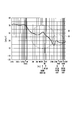
- FIGS. 7A and 7B are graphs of electromagnetic noise when the motor is driven.
- the vertical axis represents the intensity of the electromagnetic noise [dB ⁇ V], and the horizontal axis represents the frequency [Hz].
- FIG. 7A shows a case where the choke coil 46 is wound as in the first embodiment.
- FIG. 7B shows a case where the choke coil 46 is wound in the direction opposite to that in FIG. 7A.
- electromagnetic noise in a high frequency region is reduced (see part A in FIG. 7A).
- the electromagnetic noise in the intermediate frequency range is slightly increased (see part B in FIG. 7A).
- each brush holder 43 and holder stays 44 a and 44 b corresponding to each brush holder 43 are integrally formed. Therefore, according to the above-described first embodiment, the workability of assembling the brush holder 43 can be improved as compared with the case where only the brush holder 43 is assembled to the gear casing 3 as in the prior art.
- the function of the holder stays 44a and 44b is not provided on the gear casing 3 side but on the brush holder 43 side, so that the parts for assembling the brush 5 are enlarged without increasing the size of the motor 1 with a reduction gear.
- the holder stays 44a and 44b are formed separately so as to correspond to the pair of brushes 5, respectively. For this reason, the assembly workability
- labyrinth portions 56 a and 56 b are formed in the gap between the peripheral edge of the recess 38 formed in the upper case 31 of the gear casing 3 and the peripheral edge of the cover main body 52 of each unit 41 and 42. That is, the labyrinth portion 56 a is provided between the periphery of the recess 38 and the periphery of the holder stay 44 a corresponding to the periphery of the recess 38.
- the units 41 and 42 are provided with the GND terminals 61a and 61b divided so as to correspond to each other, the influence of electromagnetic noise can be suppressed.
- the brush 5, the brush holder 43, the holder stays 44 a and 44 b, and the electromagnetic shields 61 a and 61 b are assembled to the gear casing 3 in a state of being integrated for each pair of brushes 5. Therefore, the brush 5, the brush holder 43, the holder stays 44a and 44b, and the electromagnetic shields 61a and 61b can be assembled together, and the assembly workability can be further improved.
- the GND terminals 61a and 61b are in a state in which the Y terminal portions 64 are arranged to face each other, and the yoke housing 6 is connected via a bolt 10 for fastening and fixing the gear casing 3 and the yoke housing 6 respectively. And is electrically connected. For this reason, when the yoke housing 6 is attached to the gear casing 3, the GND terminals 61a and 61b can be attached to the gear casing 3 at the same time, which facilitates assembly work and suppresses electromagnetic noise generated from the electric motor 2. It becomes possible.
- the motor 1 with a speed reducer is disposed with the GND terminal 61a and the output shaft 20a facing the roof 502, the influence of electromagnetic noise on the antenna installed on the roof 502 of the vehicle 501 is prevented. can do. For this reason, the highly reliable sunroof drive device 500 can be provided.
- FIG. 8 is a perspective view of the motor 100 with a speed reducer in the second embodiment.
- FIG. 9 is an exploded perspective view of the brush unit 104 in the second embodiment.
- the basic configuration of the motor 100 with reduction gear is the same as that of the first embodiment described above in the following points.
- the reduction gear motor 100 is used in the sunroof driving device 500 and attached to the roof 502 of the vehicle 501.
- the motor 100 with a reduction gear includes the electric motor 2 and a gear casing 3 in which the reduction mechanism 20 is housed, and a brush unit 104 is attached to an upper case 31 of the gear casing 3.
- the electric motor 2 is a so-called brush motor that supplies power using the brush 5.
- the difference between the second embodiment and the first embodiment is that the brush unit 4 of the first embodiment is provided with a choke coil 46 and a capacitor 47, whereas the second embodiment is different from the second embodiment.
- the brush unit 104 is not provided with the choke coil 46 and the capacitor 47.
- the brush unit 104 includes two units 141 and 142, a first unit 141 and a second unit 142, so as to correspond to the pair of brushes 5 and 5.
- the basic configuration of the two units 141 and 142 is the same, and each component is formed substantially symmetrically with respect to the commutator 15.
- the second unit 142 will be described only with respect to a portion different in shape from the first unit 141, and the same configuration as the first unit 141 is denoted by the same reference numeral as the first unit 141 and description thereof is omitted.
- the first unit 141 is detachably provided on the upper surface 31a of the upper case 31 constituting the gear casing 3, and the outer surface side is covered with the GND terminal 161a. That is, the motor 100 with a speed reducer is arranged with the GND terminals 161a and 161b facing the roof 502 side. As a result, the GND terminals 161 a and 161 b are disposed between the roof 502 and the brush 5.
- the first unit 141 has a holder stay 144a in which a brush holder 143 for housing the brush 5 is integrally formed.
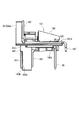
- FIG. 10 is a side view of the first unit 141.
- FIG. 11 is a front view of the first unit 141.
- the holder stay 144a of the first unit 141 is made of resin.
- the holder stay 144 a is integrally formed on the upper part of the brush holder 143 so as to be disposed on the outer surface of the gear casing 3.
- the holder stay 144a has a base portion 145a formed along the recess 38 of the upper case 31.
- a front wall 146 that rises so as to correspond to the outer flange portion 37 of the gear casing 3 is integrally formed on the electric motor 2 side (left side in FIG. 10) of the base portion 145a.
- a flange 54 having an L-shaped cross section is formed so as to extend toward the electric motor 2 side.
- the flange portion 54 is formed so as to surround the periphery of the outer flange portion 37 of the gear casing 3.
- the labyrinth portion 56 a is formed in the gap between the holder stay 144 a and the gear casing 3 by the flange portion 54 and the convex portion 55 formed on the outer flange portion 37.
- the side edge 145 c of the base portion 145 a opposite to the second unit 142 protrudes outward from the peripheral edge of the recess 38 of the gear casing 3. Is formed.
- a labyrinth portion 56b is formed in the gap between the holder stay 144a and the gear casing 3 by the side edge 145c of the base portion 145a, the peripheral edge of the recess 38 of the gear casing 3, and a GND terminal 161a described later.
- an engaging portion 130 for attaching the GND terminal 161a is integrally formed on the upper surface of the base portion 145a.
- the brush holder 143 is provided with a spring stopper 151 for closing the opening 143a on the base end side (the front side in FIG. 10) of the brush 5.
- the spring stopper 151 is formed of a resin plate material in a rectangular shape in plan view so as to correspond to the opening 143a of the brush holder 143.
- a claw portion 153 that is bent and extends so as to wrap around the lower surface 143 b of the brush holder 143 is formed.
- a tongue-like portion 152 that protrudes toward the electric motor 2 in FIG. 8 is formed at the upper end of the spring stopper 151.
- a notch portion 147 capable of receiving the tongue-like portion 152 is formed at a portion corresponding to the tongue-like portion 152 of the brush holder 143.
- the spring stopper 151 is attached to the opening 143 a of the brush holder 143 by engaging the notch 147 with the tongue 152 and engaging the claw 153 with the lower surface 143 b of the brush holder 143.
- the notch part 147 formed in the brush holder 143 is open to the outside of the commutator 15 as shown in FIG.
- the base portion 145a is slightly cut so that the upper end of the notch 147 is located above the upper end of the opening.
- the length L1 in the longitudinal direction of the notch 147 is set to be longer than the length L2 in the longitudinal direction of the tongue-like portion 152 of the spring stopper 151.
- the tongue-shaped part 152 can be slightly slid along the longitudinal direction of the brush holder 143 toward the base part 145a.
- the brush holder 143 accommodates a coil spring 21 that urges the brush 5 toward the commutator 15.
- the coil spring 21 positively biases the brush 5 toward the commutator 15 by attaching the spring stopper 151 to the brush holder 143.
- the GND terminal 161a is formed by, for example, pressing a metal plate made of brass or the like.
- the GND terminal 161 a has a terminal base 162 that covers the base portion 145 a of the spring stopper 151.
- the terminal base 162 is formed with a bent front wall shield portion 163 that covers one surface of the front wall 146 formed integrally with the holder stay 144a.
- a Y terminal portion 64 is integrally formed with the front wall shield portion 163.
- the Y terminal portion 64 in the second embodiment has a gap S between the Y terminal portions 64 and 64 as shown in FIG. 8 with the units 141 and 142 attached to the gear casing 3. It is formed.
- the side edge 162 a of the terminal base 162 opposite to the second unit 142 extends outward from the base portion 145 a of the spring stopper 151. This extended portion constitutes a part of the labyrinth portion 56b.
- the terminal base 162 is integrally formed with an auxiliary shield part 164 that extends toward the second unit 142 on the side opposite to the front wall shield part 163.
- the terminal base 162 has a claw that can be engaged with the engaging portion 130 at a portion between the front wall shield portion 163 and the auxiliary shield portion 164 and corresponding to the engaging portion 130 of the holder stay 144a.
- a portion 168 is formed to extend.
- the engaging portion 130 of the holder stay 144a is formed with a hole 130a into which the claw portion 168 of the GND terminal 161a can be press-fitted.
- the holder stay 144a and the GND terminal 161a are integrated by press-fitting the claw portion 168 into the hole 130a.
- the GND terminal 161b of the second unit 142 is extended on the side opposite to the front wall shield part 163 of the terminal base 162b so that the GND terminal 63 is bent downward.
- the GND terminal 161a of the first unit 141 is formed on the side opposite to the front wall shield part 163 of the terminal base 162 so that a tongue-like part 167 bends downward instead of the GND terminal 63. Yes.
- a slit 129 is formed at a portion corresponding to the tongue-shaped portion 167, and the tongue-shaped portion 167 is inserted therein. Thereby, rattling of the GND terminal 161a of the first unit 141 is prevented.
- FIG. 11 is an explanatory diagram showing a method for assembling the brush unit 104.
- the first unit 141 and the second unit 142 constituting the brush unit 104 are assembled in the same manner. Therefore, in the following description, only the assembly method of the first unit 141 will be described, and the description of the assembly method of the second unit 142 will be omitted.
- the male terminal 49 is attached to the holder stay 144a, the brush 5 is accommodated in the brush holder 143, and the pigtail 50 (not shown in the second embodiment) of the brush 5 and the male terminal 49 are connected by soldering or the like.
- the coil spring 21 (not shown in the second embodiment) is accommodated from the base end side (right side in FIG. 11) of the brush 5 of the brush holder 143, and the spring stopper 151 is attached.
- the GND terminal 161a is attached to the holder stay 144a.
- the first unit 141 and the second unit 142 are attached to the recess 38 of the gear casing 3.
- the units 141 and 142 are assembled from above the upper case 31 with the brush holders 143 and 143 of the units 141 and 142 facing the concave portion 38 (see arrow Y2 in FIG. 11).
- the units 141 and 142 are assembled by pressing the tip of the brush 5 using a jig (not shown) so that the tip of the brush 5 stored in the brush holder 43 does not protrude. Then, the jig is removed while inserting the brush holders 143 and 143 into the storage portion 38a of the recess 38.
- the claw portion 153 of the spring stopper 151 may collide with the peripheral wall 3 a of the gear casing 3.
- an upward force acts on the claw portion 153 as indicated by an arrow Y3 in FIG.
- an upward force acts on the tongue-like portion 152 as indicated by an arrow Y4 in FIG.
- the length L1 in the longitudinal direction of the notch 147 formed in the brush holder 143 is set to be longer than the length L2 in the longitudinal direction of the tongue-shaped portion 152 of the spring stopper 151.
- the tongue-shaped portion 152 slightly slides toward the base portion 145a along the longitudinal direction of the brush holder 143. For this reason, it is possible to prevent the spring stopper 151 from dropping from the brush holder 143.
- the GND terminals 161 a and 161 b are fastened and fixed to the gear casing 3 with the bolts 10. Thereby, the assembly of the first unit 141 and the second unit 142 is completed.
- the same effects as those of the first embodiment described above can be obtained. Further, as in the first embodiment described above, by preparing the motor 100 with a reduction gear without the choke coil 46 and the capacitor 47, variations of the motor with the reduction gear can be increased. For this reason, it becomes possible to provide the motor with a suitable reduction gear according to a user's request.
- the motors 1 and 100 with reduction gears include the electric motor 2 and the gear casing 3 in which the reduction mechanism 20 is housed, and the brush units 4 and 104 are mounted on the upper case 31 of the gear casing 3. The case where it is attached has been described. However, the invention is not limited to this, and the brush units 4 and 104 may be attached to the electric motor 2 alone.
- the assembling workability of the brush holder can be improved and the assembling accuracy of the brush holder can be increased.
Landscapes
- Engineering & Computer Science (AREA)
- Power Engineering (AREA)
- Physics & Mathematics (AREA)
- Electromagnetism (AREA)
- Motor Or Generator Frames (AREA)
- Connection Of Motors, Electrical Generators, Mechanical Devices, And The Like (AREA)
Abstract
アーマチュアに設けられているコンミテータを挟んで両側に配置され、前記コンミテータに摺接して給電を行う一対のブラシ(5)と、これら一対のブラシ(5)をコンミテータに対して進退可能に収納する一対のブラシホルダ(43)と、ブラシホルダ(43)を支持するホルダステー(44a),(44b)とを備える電動モータ、減速機付モータ、およびサンルーフ駆動措置である。ブラシホルダ(43)とホルダステー(44a),(44b)とを樹脂により一体成形し、かつホルダステー(44a),(44b)を各ブラシホルダ(43)に対応するように分割して配置した。
Description
この発明は、電動モータ、減速機付モータ、およびこれらを用いたサンルーフ駆動装置に関するものである。
本願は、2010年4月27日に、日本に出願された特願2010-102140号に基づき優先権を主張し、その内容をここに援用する。
本願は、2010年4月27日に、日本に出願された特願2010-102140号に基づき優先権を主張し、その内容をここに援用する。
従来から、電動モータと、この電動モータの回転軸に連結する減速機構を収納したギヤケーシングとが一体化された減速機付モータが知られている。この種の電動モータとしては、例えばアーマチュアと、アーマチュアのコンミテータに摺接(スライド可能に接触)する一対のブラシとを備えたブラシ付モータがある。
一対のブラシは、それぞれブラシホルダに収納された形でギヤケーシングに取り付けられている。ブラシホルダは樹脂により形成されたものであって、各ブラシに対応するように2つ設けられている。一対のブラシホルダは、それぞれギヤケーシングに対して着脱可能に構成されている(例えば、特許文献1参照)。
一対のブラシは、それぞれブラシホルダに収納された形でギヤケーシングに取り付けられている。ブラシホルダは樹脂により形成されたものであって、各ブラシに対応するように2つ設けられている。一対のブラシホルダは、それぞれギヤケーシングに対して着脱可能に構成されている(例えば、特許文献1参照)。
しかしながら、上述の従来技術にあっては、ギヤケーシングに小さい部品のブラシホルダのみを装着するので、ブラシホルダを組み付けにくく、かつブラシホルダの組み付け精度を高めにくいという課題がある。
そこで、この発明は、上述した事情に鑑みてなされたものであって、ブラシホルダの組み付け作業性を向上でき、かつブラシホルダの組み付け精度を高めることができる電動モータ、減速機付モータ、およびサンルーフ駆動装置を提供する。
上記の課題を解決する本発明の第1の態様に係る電動モータは、アーマチュアと、前記アーマチュアに設けられているコンミテータを挟んで両側に配置され、前記コンミテータに摺接して給電を行う一対のブラシと、これら一対のブラシをコンミテータに対して進退可能に収納する一対のブラシホルダと、前記ブラシホルダを支持するホルダステー(holder stay)とを備える。そして、前記ブラシホルダと前記ホルダステーとを樹脂により一体成形すると共に、前記ホルダステーを、各ブラシホルダに対応するように分割して配置する。
このように、各ブラシホルダにそれぞれホルダステーを一体化するので、従来のように、ブラシホルダのみをギヤケーシングに対して組み付ける場合と比較して、ブラシホルダの組み付け作業性を向上することができる。
すなわち、モータ全体を大型化することなく、ブラシを組み付けるための部品を大型化できる。これに加え、ホルダステーがそれぞれのブラシホルダに対応して別々に構成されている。
このため、ブラシホルダの組み付け作業性を向上することができる。
また、部品を大型化することで、部品の寸法管理が容易となり、ブラシホルダの組み付け精度を高めることができる。
すなわち、モータ全体を大型化することなく、ブラシを組み付けるための部品を大型化できる。これに加え、ホルダステーがそれぞれのブラシホルダに対応して別々に構成されている。
このため、ブラシホルダの組み付け作業性を向上することができる。
また、部品を大型化することで、部品の寸法管理が容易となり、ブラシホルダの組み付け精度を高めることができる。
本発明の第2の態様に係る減速機付モータは、上記の電動モータと、この電動モータに一体的に取り付けられるギヤケーシングと、前記ギヤケーシング内に収納され、前記電動モータの回転軸に連結される減速機構とを備える。また、前記ギヤケーシングに前記ホルダステー、およびブラシホルダを収納する収納凹部を形成し、この収納凹部に前記ホルダステー、およびブラシホルダを取り付ける。さらに、前記収納凹部の周縁と、前記ホルダステーの前記周縁に対応する部位との間に、ラビリンス部を設ける。
このように構成することで、収納凹部、ホルダステー、およびブラシホルダの加工精度を緩和した場合であっても、収納凹部とホルダステーとの間隙、および収納凹部とブラシホルダとの間隙からの塵埃の侵入を防止できる。このため、製造コストを低減しつつ、塵埃の侵入による影響を抑制することが可能になる。
上記の減速機付モータにおいて、各ホルダステーの外側に、それぞれ電磁ノイズによる影響を抑制するための電磁シールドを設けてもよい。
通電状態のブラシがコンミテータの隣り合うセグメントを跨いだときに自己誘導作用によりサージ電圧が発生し、このサージ電圧によりブラシとコンミテータとが摺接する部分から電磁ノイズが放射されることがある。このため、例えば減速機付モータを車両に搭載すると、電磁ノイズにより他の電装品等に影響を及ぼす可能性がある。
しかしながら、ホルダステーの外側に電磁シールドを設けることによって、電磁ノイズによる影響を抑制することができる。
しかしながら、ホルダステーの外側に電磁シールドを設けることによって、電磁ノイズによる影響を抑制することができる。
上記の減速機付モータにおいて、各ホルダステーに、それぞれ前記電磁シールドを取り付け、前記ホルダステー、ブラシホルダ、および電磁シールドを一体化させた状態で、これらホルダステー、ブラシホルダ、および電磁シールドを前記ギヤケーシングに取り付けてもよい。
このように構成することで、ギヤケーシングに、ブラシ、ブラシホルダ、ホルダステー、および電磁シールドを一体化させた状態で組み付けることができる。このため、さらに組み付け作業性を向上することができる。
上記の減速機付モータにおいて、前記電磁シールドは、各ホルダステーに対応するように分割して配置され、各電磁シールドは前記電動モータと前記ギヤケーシングを取り付けるための締結手段により前記ギヤケーシングに取り付けられていてもよい。
このように構成することで、電動モータとギヤケーシングを取り付ける際に、同時に電磁シールドをギヤケーシングに取り付けることができ、組み付け作業が容易になる。さらに、締結手段を介して各電磁シールドと電動モータのヨークハウジングとが電気的に接続されるため、電動モータから発生する電磁ノイズを抑制することが可能になる。
本発明の第3の態様に係るサンルーフ駆動装置は、上記の減速機付モータを車両のルーフに設け、このルーフに設けられているルーフパネルを、前記減速機付モータを用いて駆動するサンルーフ駆動装置である。この態様において、前記減速機付モータは、前記電磁シールドを前記ルーフ側に向けた状態で配置される。
このように構成することで、車両のルーフに設置されるアンテナ等への電磁ノイズによる影響を防止することができる。このため、信頼性の高いサンルーフ駆動装置を提供できる。
本発明によれば、各ブラシホルダにそれぞれホルダステーを一体化するので、ブラシホルダのみをギヤケーシングに対して組み付ける場合と比較してブラシホルダの組み付け作業性を向上することができる。
すなわち、モータ全体を大型化することなく、ギヤケーシングに組み付ける部品を大型化できる。これに加え、ホルダステーごとブラシホルダに対応して別々に構成されている。
このため、ブラシホルダの組み付け作業性を向上することができる。
また、部品を大型化することで、部品の寸法管理が容易となり、ブラシホルダの組み付け精度を高めることができる。
すなわち、モータ全体を大型化することなく、ギヤケーシングに組み付ける部品を大型化できる。これに加え、ホルダステーごとブラシホルダに対応して別々に構成されている。
このため、ブラシホルダの組み付け作業性を向上することができる。
また、部品を大型化することで、部品の寸法管理が容易となり、ブラシホルダの組み付け精度を高めることができる。
(第一実施形態)
(サンルーフ駆動装置)
次に、この発明の第一実施形態を図1~図7に基づいて説明する。
図1は、サンルーフ駆動装置500の概略構成図である。
同図に示すように、サンルーフ駆動装置500は、車両501のルーフ502に取り付けられ、ルーフ502に設けられているルーフパネル503を駆動する。サンルーフ駆動装置500は、減速機付モータ1を備えている。ルーフ502には、開口部502aが形成されており、この開口部502aを開閉可能にルーフパネル503が設けられている。ルーフパネル503には、ケーブル504a,504bの一端が連結されている。ケーブル504a,504bの他端は減速機付モータ1に連結されており、減速機付モータ1が駆動することによって、ルーフパネル503が開口部502aを開閉する。減速機付モータ1は、ルーフ502の開口部502aとフロントガラス505との間に配置されている。
(サンルーフ駆動装置)
次に、この発明の第一実施形態を図1~図7に基づいて説明する。
図1は、サンルーフ駆動装置500の概略構成図である。
同図に示すように、サンルーフ駆動装置500は、車両501のルーフ502に取り付けられ、ルーフ502に設けられているルーフパネル503を駆動する。サンルーフ駆動装置500は、減速機付モータ1を備えている。ルーフ502には、開口部502aが形成されており、この開口部502aを開閉可能にルーフパネル503が設けられている。ルーフパネル503には、ケーブル504a,504bの一端が連結されている。ケーブル504a,504bの他端は減速機付モータ1に連結されており、減速機付モータ1が駆動することによって、ルーフパネル503が開口部502aを開閉する。減速機付モータ1は、ルーフ502の開口部502aとフロントガラス505との間に配置されている。
(減速機付モータ)
図2は、減速機付モータ1の斜視図である。図3は、減速機付モータ1の分解斜視図である。
図2、図3に示すように、減速機付モータ1は、電動モータ2と、減速機構20が収納されたギヤケーシング3とを備え、ギヤケーシング3にブラシユニット4が取り付けられている。
減速機構20は、電動モータ2の動力が伝達されるウォーム軸と、このウォーム軸に噛合うウォームホイール(何れも不図示)と、ウォームホイールに連結された出力軸20aとにより構成されている。ケーブル504a,504bの他端は、出力軸20aに連結されている。
図2は、減速機付モータ1の斜視図である。図3は、減速機付モータ1の分解斜視図である。
図2、図3に示すように、減速機付モータ1は、電動モータ2と、減速機構20が収納されたギヤケーシング3とを備え、ギヤケーシング3にブラシユニット4が取り付けられている。
減速機構20は、電動モータ2の動力が伝達されるウォーム軸と、このウォーム軸に噛合うウォームホイール(何れも不図示)と、ウォームホイールに連結された出力軸20aとにより構成されている。ケーブル504a,504bの他端は、出力軸20aに連結されている。
このような減速機構20を収納するギヤケーシング3は、樹脂により形成され、上ケース31と下ケース32とに分割可能であり、上ケース31に減速機構20を収納することができるように構成されている。減速機付モータ1は、上ケース31をルーフ502側に向け、出力軸20aをルーフ502側に向けた状態で、ルーフ502の車室側に取り付けられている。
下ケース32には、電動モータ2を駆動するための回路基板33が収納されている。回路基板33には、ブラシユニット4と接続可能な雌端子35aが実装されている。
下ケース32には、不図示の外部コネクタを接続可能なコネクタ部34が設けられている。コネクタ部34と回路基板33は、互いに電気的に接続されている。
下ケース32には、電動モータ2を駆動するための回路基板33が収納されている。回路基板33には、ブラシユニット4と接続可能な雌端子35aが実装されている。
下ケース32には、不図示の外部コネクタを接続可能なコネクタ部34が設けられている。コネクタ部34と回路基板33は、互いに電気的に接続されている。
ここで、上ケース31には、電動モータ2が取り付けられる箇所に、電動モータ2の一部を収納可能な電動モータ収納部36が形成されている。この電動モータ収納部36の外周部には、電動モータ2を取り付けるための外フランジ部37が一体形成されている。上ケース31は、外フランジ部37を挟んで電動モータ2とは反対側に、ブラシユニット4が取り付けられる。
電動モータ2は、ブラシ5を用いて給電を行う所謂ブラシ付モータである。電動モータ2は、開口部6aと底壁6bを有する筒状のヨークハウジング6と、ヨークハウジング6内に回転可能に設けられたアーマチュア7とを有している。
ヨークハウジング6は、開口部6aをギヤケーシング3側に向けた状態でギヤケーシング3に取り付けられる。ヨークハウジング6の周壁6bの開口部6aに近い部位には、ナット8を挿入可能なスリット9が2箇所形成されている。
ヨークハウジング6は、開口部6aをギヤケーシング3側に向けた状態でギヤケーシング3に取り付けられる。ヨークハウジング6の周壁6bの開口部6aに近い部位には、ナット8を挿入可能なスリット9が2箇所形成されている。
ギヤケーシング3の外フランジ部37には、ヨークハウジング6のスリット9に挿入されたナット8に対応する部位に、締結手段としてのボルト10を挿入可能な挿入孔27が形成されている。この挿入孔27にボルト10を挿入すると共に、ナット8にボルト10を螺入することにより、ギヤケーシング3にヨークハウジング6が締結されて固定される。
また、ヨークハウジング6の周壁6bには、内側面に永久磁石13が設けられている。
さらに、ヨークハウジング6の底壁6cには、アーマチュア7の回転軸11の一端を回転可能に支持するための軸受部12が設けられている。軸受部12は、回転軸11の軸方向において底壁6cからヨークハウジング6の外側に向かって突出している。
また、ヨークハウジング6の周壁6bには、内側面に永久磁石13が設けられている。
さらに、ヨークハウジング6の底壁6cには、アーマチュア7の回転軸11の一端を回転可能に支持するための軸受部12が設けられている。軸受部12は、回転軸11の軸方向において底壁6cからヨークハウジング6の外側に向かって突出している。
アーマチュア7は、回転軸11と、アーマチュアコア14と、コンミテータ15とを備えている。アーマチュアコア14は、回転軸11の外周部の永久磁石13に対応する部位に嵌められて固定されている。コンミテータ15は、回転軸11の外周部のギヤケーシング3に近い部位に嵌められて固定されている。アーマチュアコア14には巻線16が巻き付けられて装着されており、この巻線16の端末部がコンミテータ15に接続されている。
コンミテータ15は円柱状に形成され、ギヤケーシング3の電動モータ収納部36内壁に面して配置される。コンミテータ15は、この外周面に、板状に形成された不図示の複数のセグメントが並ベられて設置されている。これらセグメントに、巻線16の端末部が接続されている。また、コンミテータ15には、このコンミテータ15を挟んで両側に配置されたブラシユニット4を構成する一対のブラシ5,5が摺接する。
(ブラシユニット)
図4は、ブラシユニット4の分解斜視図である。図5は、ブラシユニット4を構成する第1ユニット41の縦断面図である。
図3~図5に示すように、ブラシユニット4は、一対のブラシ5,5に対応するように、第1ユニット41、および第2ユニット42の2つのユニット41,42により構成されている。
図4は、ブラシユニット4の分解斜視図である。図5は、ブラシユニット4を構成する第1ユニット41の縦断面図である。
図3~図5に示すように、ブラシユニット4は、一対のブラシ5,5に対応するように、第1ユニット41、および第2ユニット42の2つのユニット41,42により構成されている。
ここで、2つのユニット41,42の基本的構成は同一であり、各構成部品はコンミテータ15に対してほぼ対称に形成されている。このため、以下の説明においては、第1ユニット41のみ詳細に説明する。第2ユニット42については、第1ユニット41と形状が異なる部位のみ説明し、第1ユニット41と共通の構成については第1ユニット41と同一符号を付して説明を省略する。
第1ユニット41は、ギヤケーシング3を構成する上ケース31の下ケース32とは反対側(図3~図5における上側、以下、単に上側という)の上面31aに着脱可能に設けられている。第1ユニット41の外面側はGNDターミナル61aで覆われている。つまり、GNDターミナル61aは、上ケース3に対して減速機構20の出力軸20aが配置されている側に設けられている。これにより、減速機付モータ1は、GNDターミナル61a、および出力軸20aをルーフ502側に向けた状態で配置される。
第1ユニット41は、ブラシ5を収納するためのブラシホルダ43が一体成形されているホルダステー44aを有している。第2ユニット42も同様のホルダステー44bを有している。すなわち、本実施形態においては、ホルダステー44a,44bが、第1ユニット41および第2ユニットの各ブラシホルダ43に対応するように分割して配置されている。
第1ユニット41は、ブラシ5を収納するためのブラシホルダ43が一体成形されているホルダステー44aを有している。第2ユニット42も同様のホルダステー44bを有している。すなわち、本実施形態においては、ホルダステー44a,44bが、第1ユニット41および第2ユニットの各ブラシホルダ43に対応するように分割して配置されている。
ブラシ5は、コンミテータ15を介して巻線16に電流を供給するためのものであって、断面形状が四角形に形成されている。ブラシ5の基端側には、ピグテール50の一端が接続されている。
ブラシホルダ43は、樹脂により形成される。ブラシホルダ43は、ブラシ5の断面形状に対応するように四角形の筒状に形成されており、両端に小開口部としての開口部443を有している。ブラシ5は、ブラシホルダ43内に、コンミテータ15に対して進退可能に収納されている。すなわち、一対のブラシホルダ43は、ブラシ5の進退方向の両端に開口部443が形成され、一対のブラシ5をコンミテータ15に対して進退可能に収納する。ブラシホルダ43は、ギヤケーシング3にブラシユニット4を取り付けた際、ギヤケーシング3内に収納される。
ブラシホルダ43は、樹脂により形成される。ブラシホルダ43は、ブラシ5の断面形状に対応するように四角形の筒状に形成されており、両端に小開口部としての開口部443を有している。ブラシ5は、ブラシホルダ43内に、コンミテータ15に対して進退可能に収納されている。すなわち、一対のブラシホルダ43は、ブラシ5の進退方向の両端に開口部443が形成され、一対のブラシ5をコンミテータ15に対して進退可能に収納する。ブラシホルダ43は、ギヤケーシング3にブラシユニット4を取り付けた際、ギヤケーシング3内に収納される。
すなわち、ギヤケーシング3には、第1ユニット41、および第2ユニット42を外側から挿入可能な凹部(収納凹部)38が形成されている。この凹部38のブラシホルダ43に対応する部位に、ブラシホルダ43を収納可能な収納部38aが形成されている。収納部38aには、ブラシ5に対応する部位に不図示の開口部が形成されている。この開口部を介してブラシ5の先端がコンミテータ15のセグメント(不図示)に摺接する。
図6は、ホルダステー44aの斜視図である。
図4~図6に示すように、ホルダステー44aは樹脂により形成され、ギヤケーシング3の外面に配置されるように、ブラシホルダ43の上面43aに一体成形されている。そして、ホルダステー44aは、上ケース31の凹部38に沿って、ブラシホルダ43から第2ユニット42側(図4における左側)に向かって突出するように形成されている。この第2ユニット42側に向かって突出した部位には、外側に大開口部としての開口部445を有する箱状の素子収納部45が形成されている。
図4~図6に示すように、ホルダステー44aは樹脂により形成され、ギヤケーシング3の外面に配置されるように、ブラシホルダ43の上面43aに一体成形されている。そして、ホルダステー44aは、上ケース31の凹部38に沿って、ブラシホルダ43から第2ユニット42側(図4における左側)に向かって突出するように形成されている。この第2ユニット42側に向かって突出した部位には、外側に大開口部としての開口部445を有する箱状の素子収納部45が形成されている。
素子収納部45は、ノイズ防止素子としてのチョークコイル46、およびコンデンサ47を収納する収納部本体40aと、ブラシ5のピグテール50を収納するためピグテール収納部40bとが一体成形されたものである。収納部本体40aとピグテール収納部40bとは連通している。収納部本体40aの底壁45aには、ピグテール収納部40bの近傍に、雄端子49が設けられている。
雄端子49は、底壁45aから第1ユニット41の着脱方向(図4、図5における上下方向)に沿って延出するように形成されている。雄端子49は、上ケース31に第1ユニット41を取り付けた状態で下ケース32に収納されている回路基板33の雌端子35aに接続される。
チョークコイル46は、素子収納部45において第2ユニット42寄りの位置に収納されている。
チョークコイル46の一端には、ピグテール50の他端が接続されている。また、チョークコイル46は、心棒48の周囲に巻き回されている。
チョークコイル46を巻き回す方向は、チョークコイル46の一端側、つまり、心棒48の一端側(図6におけるピグテール収納部40bに近い端部)から他端側(図6におけるピグテール収納部40bから遠い端部)に向かって左回り方向(図6における矢印Y1参照)に設定されている。
チョークコイル46の一端には、ピグテール50の他端が接続されている。また、チョークコイル46は、心棒48の周囲に巻き回されている。
チョークコイル46を巻き回す方向は、チョークコイル46の一端側、つまり、心棒48の一端側(図6におけるピグテール収納部40bに近い端部)から他端側(図6におけるピグテール収納部40bから遠い端部)に向かって左回り方向(図6における矢印Y1参照)に設定されている。
チョークコイル46の他端は、雄端子49に接続されている。これにより、回路基板33の雌端子35a、第1ユニット41の雄端子49、チョークコイル46、およびピグテール50を介してブラシ5に電流が供給される。
また、雄端子49には、コンデンサ47の一端が接続されている。コンデンサ47は、素子収納部45における第2ユニット42とは反対側(図4、図6における右側)、つまり、チョークコイル46の外側に収納されている。
さらに、コンデンサ47の他端は、GNDターミナル61aに接続されている。これにより、チョークコイル46は、ブラシ5と雄端子49との間の給電ライン上に直列に接続された状態になる。一方、チョークコイル46と並列に、コンデンサ47が設けられた状態になる。このように、チョークコイル46、およびコンデンサ47が収納されたホルダステー44aには、この外側を閉塞するカバー51aが取り付けられている。
さらに、コンデンサ47の他端は、GNDターミナル61aに接続されている。これにより、チョークコイル46は、ブラシ5と雄端子49との間の給電ライン上に直列に接続された状態になる。一方、チョークコイル46と並列に、コンデンサ47が設けられた状態になる。このように、チョークコイル46、およびコンデンサ47が収納されたホルダステー44aには、この外側を閉塞するカバー51aが取り付けられている。
図3~図5に示すように、カバー51aは、カバー本体52と、スプリングストッパ53とが一体形成されて構成される。カバー本体52は、ホルダステー44aの収納部本体40aの開口と、ピグテール収納部40bの一部の開口である素子収納部45の開口部445を閉塞する。スプリングストッパ53は、ピグテール収納部40bの一部の開口と、ブラシホルダ43の基端側の開口部443を閉塞する。
スプリングストッパ53の先端には、ブラシホルダ43の下面43bに回り込むように屈曲して延出する爪部53aが形成されている。この爪部53aとカバー本体52とによってブラシホルダ43およびホルダステー44aを挟んで保持することで、ホルダステー44aにカバー51aが取り付けられる。スプリングストッパ53は、ブラシホルダ43とホルダステー44aの一部と共に、ギヤケーシング3の凹部38に形成されている収納部38aに収納される。
ここで、ブラシホルダ43には、ブラシ5をコンミテータ15側に向かって付勢するコイルスプリング21が収納されている。カバー51aがブラシホルダ43に取り付けられると、カバー51aのスプリングストッパ53によってコイルスプリング21の一端が支持される。これにより、コイルスプリング21の他端が確実にブラシ5をコンミテータ15側に向かって付勢する。
一方、カバー本体52の電動モータ2側(図5における左側)の側縁52aには、断面形状がL字状の鉤部54が電動モータ2側に向かって延出するように形成されている。また、鉤部54は、ギヤケーシング3の外フランジ部37の周縁を取り囲むように形成されている。
一方、外フランジ部37の周縁には、鉤部54の内側に面して配置される凸部55が形成されている。凸部55は外フランジ部37の周縁に沿って連続的に形成されている。本実施形態の凸部55は、円弧状の外フランジ部37の周縁に沿って円弧状に形成されている。
ギヤケーシング3にブラシユニット4を取り付けた状態において、鉤部54と、凸部55とにより、カバー本体52とギヤケーシング3との間隙に、ラビリンス部56aが形成さる。
一方、外フランジ部37の周縁には、鉤部54の内側に面して配置される凸部55が形成されている。凸部55は外フランジ部37の周縁に沿って連続的に形成されている。本実施形態の凸部55は、円弧状の外フランジ部37の周縁に沿って円弧状に形成されている。
ギヤケーシング3にブラシユニット4を取り付けた状態において、鉤部54と、凸部55とにより、カバー本体52とギヤケーシング3との間隙に、ラビリンス部56aが形成さる。
ギヤケーシング3にブラシユニット4を取り付けた状態において、カバー本体52のスプリングストッパ53側の側縁52bは、ギヤケーシング3の凹部38の周縁よりも外側、つまり、第2ユニット42とは反対側に向かって突出するように形成されている。そして、これらカバー本体52の側縁52bとギヤケーシング3の凹部38の周縁、およびGNDターミナル61aによって、カバー本体52とギヤケーシング3との間隙に、ラビリンス部56a,56bが形成される。ここで、カバー本体52の周縁は、凹部38とホルダステー44aの周縁との間に配置されている。すなわち、ラビリンス部56a,56bは、凹部38の周縁と、この凹部38の周縁に対応するホルダステー44aの周縁との間に設けられている。
カバー本体52には、ギヤケーシング3の外フランジ部37とは反対側(図5における左側)の側壁57に、切り欠き部58が形成されている。この切り欠き部58は、GNDターミナル61aに形成されている後述の凸部65と係合することで、ホルダステー44aとGNDターミナル61aとを一体化する。
GNDターミナル61aは、例えば真鍮等からなる金属板をプレス加工等を施すことによって形成される。GNDターミナル61aは、カバー51aのカバー本体52を外側から覆うターミナル本体62と、ターミナル本体62の周縁から下ケース32側(図3~図5における下側、以下、単に下側という)に向かって延出するGND端子63とを一体成形することにより形成されている。
ターミナル本体62におけるギヤケーシング3の外フランジ部37側には、挿入孔27に対応する部位に、Y端子部64が一体成形されている。すなわち、2つのユニット41,42の各GNDターミナル61a,61bは、互いにY端子部64が対向配置された状態になっている。Y端子部64は、ギヤケーシング3の外フランジ部37、および電動モータ2のヨークハウジング6と共に、ボルト10、ナット8により締結される。これにより、GNDターミナル61aがギヤケーシング3に締結されて固定され、GNDターミナル61aによってホルダステー44aの抜け方向への移動が規制される。
また、Y端子部64は、ギヤケーシング3とヨークハウジング6を締結して固定するためのボルト10を介し、第2ユニット42のGNDターミナル61bに形成されているY端子部64、およびヨークハウジング6と電気的に接続される。すなわち、GNDターミナル61a,61bは、従来は一体であったGNDターミナルを一対のブラシ5,5に対応するように分割した構造になっている。
第1ユニット41のY端子部64と、第2ユニット42のY端子部64とをそれぞれギヤケーシング3に取り付けた状態において、Y端子部64,64間には、図2に示すように隙間Sが形成される。
第1ユニット41のY端子部64と、第2ユニット42のY端子部64とをそれぞれギヤケーシング3に取り付けた状態において、Y端子部64,64間には、図2に示すように隙間Sが形成される。
また、ターミナル本体62には、ホルダステー44aの側壁57と重なり合う側壁66に、凸部65がホルダステー44aの側壁57側に向かって突出するように形成されている。凸部65は、ホルダステー44aに形成されている切り欠き部58に対応する位置に配置されており、この切り欠き部58と係合する。これにより、ホルダステー44a、カバー51a、およびGNDターミナル61aが一体化される。
また、ターミナル本体62の第2ユニット42とは反対側の側縁62aは、カバー本体52の側縁52bを覆うように側縁52bよりも下側に向かって延出するように形成されている。この延出した部分がラビリンス部56bの一部を構成する。
また、ターミナル本体62の第2ユニット42とは反対側の側縁62aは、カバー本体52の側縁52bを覆うように側縁52bよりも下側に向かって延出するように形成されている。この延出した部分がラビリンス部56bの一部を構成する。
GNDターミナル61aのGND端子63は、上ケース31を貫通して下ケース32に収納されている回路基板33に至るまで延出している。回路基板33には、GND端子63に接続可能な雌端子35bが実装されている。雌端子35bにGND端子63が接続されることにより、GNDターミナル61a,61bがGNDに接地された状態になる。
ここで、図4に基づいて、第1ユニット41を構成するホルダステー44aおよびGNDターミナル61aの形状に対して、第2ユニット42を構成するホルダステー44b、およびGNDターミナル61bの形状が異なる点について説明する。
まず、第1ユニット41のホルダステー44aでは、収納部本体40aの底壁45aにおけるピグテール収納部40bの近傍に、雄端子49が立った状態で設けられている。これに対し、第2ユニット42のホルダステー44bでは、収納部本体40aの底壁45aにおけるピグテール収納部40bとは反対側に、雄端子49が立った状態で設けられている。
まず、第1ユニット41のホルダステー44aでは、収納部本体40aの底壁45aにおけるピグテール収納部40bの近傍に、雄端子49が立った状態で設けられている。これに対し、第2ユニット42のホルダステー44bでは、収納部本体40aの底壁45aにおけるピグテール収納部40bとは反対側に、雄端子49が立った状態で設けられている。
また、第1ユニット41のGNDターミナル61aには、GND端子63が設けられているが、第2ユニット42のGNDターミナル61bには、GND端子63が設けられていない。これは、第1ユニット41のGNDターミナル61aと第2ユニット42のGNDターミナル61bは、互いにボルト10を介して電気的に接続されるからである。
そして、第2ユニット42のGNDターミナル61bには、ターミナル本体62のY端子部64とは反対側に、GND端子63に代わって舌状部67が下方に向かって屈曲形成されている。一方、ギヤケーシング3の上ケース31には、舌状部67に対応する部位にスリット29が形成されている。舌状部67がスリット29に差込まれることにより、第2ユニット42のGNDターミナル61bのガタツキが防止される。
(ブラシユニットの組み付け方法)
次に、図3~図6に基づいて、ブラシユニット4の組み付け方法について説明する。ブラシユニット4を構成する第1ユニット41および第2ユニット42は、ギアケーシング3に対する組み付け方法が同じである。そのため、以下の説明において、第1ユニット41の組み付け方法についてのみ説明し、第2ユニット42の組み付け方法についての説明を省略する。
まず、ホルダステー44aに雄端子49を組み付ける。そして、チョークコイル46の一端に、ピグテール50の他端をスポット溶接等により接続する。その後、素子収納部45にチョークコイル46を収納すると共に、ブラシホルダ43にブラシ5を収納する。
次に、図3~図6に基づいて、ブラシユニット4の組み付け方法について説明する。ブラシユニット4を構成する第1ユニット41および第2ユニット42は、ギアケーシング3に対する組み付け方法が同じである。そのため、以下の説明において、第1ユニット41の組み付け方法についてのみ説明し、第2ユニット42の組み付け方法についての説明を省略する。
まず、ホルダステー44aに雄端子49を組み付ける。そして、チョークコイル46の一端に、ピグテール50の他端をスポット溶接等により接続する。その後、素子収納部45にチョークコイル46を収納すると共に、ブラシホルダ43にブラシ5を収納する。
次に、素子収納部45にコンデンサ47を収納する。素子収納部45にチョークコイル46、およびコンデンサ47を収納した後、ブラシホルダ43のブラシ5の基端側(ブラシ5が付勢される方向の後方)からコイルスプリング21を収納する。この後、ホルダステー44aにカバー51aを取り付ける。そして、雄端子49に、チョークコイル46の他端、およびコンデンサ47の一端をはんだ付け等により接続する。
続いて、カバー51aの上からGNDターミナル61aを取り付ける。このとき、GNDターミナル61aの凸部65がホルダステー44aの切り欠き部58に係合する。これにより、GNDターミナル61aがホルダステー44aから容易に脱落してしまうのを阻止できる。この状態で、GNDターミナル61aに、コンデンサ47の他端をスポット溶接等により接続する。これにより、第1ユニット41の組み立てが完了する。
続いて、ギヤケーシング3の凹部38に、第1ユニット41、および第2ユニット42を取り付ける。このとき、各ユニット41,42のブラシホルダ43,43を凹部38側に向けて、上ケース31の上方から各ユニット41,42を組み付ける。また、各ユニット41,42を組み付ける際に、ブラシホルダ43に収納されているブラシ5の先端が突出しないように、不図示の治具を用いてブラシ5の先端を押さえる。そして、凹部38の収納部38aにブラシホルダ43,43を挿入しながら、治具を取り外す。
ここで、ギヤケーシング3に、第1ユニット41、および第2ユニット42をそれぞれ別個に組み付けることができる。このため、ギヤケーシング3の製作精度によらず、各ユニット41,42をスムーズに組み付けることができる。
ここで、ギヤケーシング3に、第1ユニット41、および第2ユニット42をそれぞれ別個に組み付けることができる。このため、ギヤケーシング3の製作精度によらず、各ユニット41,42をスムーズに組み付けることができる。
すなわち、例えば、各ユニット41,42を一体成形した場合、それぞれのブラシホルダ43,43間の距離とギヤケーシング3の収納部38a,38a間の距離とに誤差が生じると各ユニット41,42の組み付けが困難になってしまう。
しかしながら、本第一実施形態においては、ギヤケーシング3に第1ユニット41、および第2ユニット42をそれぞれ別個に組み付ける。また、第1ユニット41のY端子部64と、第2ユニット42のY端子部64とをそれぞれギヤケーシング3に取り付けた状態で、図2に示すようにY端子部64,64間に隙間Sが形成される。このため、Y端子部64同士が互いに干渉することなく、各ユニット41,42の寸法誤差を吸収あるいは相殺し、確実に、かつ精度よく組み付けることができる。
しかしながら、本第一実施形態においては、ギヤケーシング3に第1ユニット41、および第2ユニット42をそれぞれ別個に組み付ける。また、第1ユニット41のY端子部64と、第2ユニット42のY端子部64とをそれぞれギヤケーシング3に取り付けた状態で、図2に示すようにY端子部64,64間に隙間Sが形成される。このため、Y端子部64同士が互いに干渉することなく、各ユニット41,42の寸法誤差を吸収あるいは相殺し、確実に、かつ精度よく組み付けることができる。
また、ギヤケーシング3の上ケース31に形成されている凹部38の周縁と、各ユニット41,42のカバー本体52の周縁との間隙に、ラビリンス部56a,56bが形成されている。すなわち、ラビリンス部56a,56bは、凹部38の周縁と、この凹部38の周縁に対応するホルダステー44aの周縁との間に設けられている。このため、上ケース31と各ユニット41,42との寸法関係を高精度に維持することなく、ギヤケーシング3内への塵埃の侵入を防止できる。換言すれば、ラビリンス部56a,56bを形成するために、上ケース31と各ユニット41,42との間にガタツキを持たせている。また、このガタツキにより、ギヤケーシング3と各ユニット41,42の寸法誤差を吸収することができる。
続いて、ギヤケーシング3に各ユニット41,42を取り付けた後、ボルト10によって、ギヤケーシング3にGNDターミナル61a,61bを締結して固定する。これにより、ギヤケーシング3への第1ユニット41、および第2ユニット42の組み付けが完了する。
このように各ユニット41,42が組み付けられた減速機付モータ1を駆動する場合、ギヤケーシング3に設けられているコネクタ部34に、不図示の外部電源に接続されている外部コネクタを接続する。そして、回路基板33を介してブラシ5に電流を供給し、さらにブラシ5が摺接されているコンミテータ15を介してアーマチュア7の巻線16に電流を供給する。
巻線16に電流が供給されると、アーマチュアコア14に磁界が発生し、ヨークハウジング6に設けられている永久磁石13との間で磁気的な吸引力や反発力が生じる。これにより、アーマチュア7が回転する。
巻線16に電流が供給されると、アーマチュアコア14に磁界が発生し、ヨークハウジング6に設けられている永久磁石13との間で磁気的な吸引力や反発力が生じる。これにより、アーマチュア7が回転する。
ここで、アーマチュア7の回転に伴って、通電状態のブラシ5がコンミテータ15のセグメント(不図示)を跨いだときに自己誘導作用によりサージ電圧が発生する。このサージ電圧によりブラシ5とコンミテータ15との摺接部分から電磁ノイズが放射されることがある。しかしながら、ブラシユニット4を構成する第1ユニット41、および第2ユニット42にそれぞれGNDターミナル61a,61bが設けられているので、電磁ノイズによる影響を抑制できる。
ここで、減速機付モータ1が取り付けられているルーフ502には、例えばカーナビゲーションシステム等の通信機器の情報送受信部として、アンテナが設置されている場合がある。このような場合、減速機付モータ1による電磁ノイズが通信機器に影響を及ぼす可能性がある。しかしながら、減速機付モータ1は、GNDターミナル61a,61bをルーフ502側に向けた状態で配置されている。すなわち、通信機器の情報送受信部とブラシ5との間にGNDターミナル61a,61bが配置されている。したがって、アンテナへの電磁ノイズによる影響を防止することができる。
また、図6に示すように、チョークコイル46は、心棒48のピグテール収納部40bに近い一端側からピグテール収納部40bと離れた他端側に向かって巻き回すとき、左回りに巻き回されている。また、コンデンサ47は、素子収納部45における第2ユニット42とは反対側(図4、図6における右側)、つまり、チョークコイル46の外側に収納されている。このため、特定の周波数域の電磁ノイズが低減される。
より詳しく図7A及び図7Bに基づいて説明する。
図7A及び図7Bは、モータ駆動時の電磁ノイズのグラフであり、縦軸は電磁ノイズの強度[dBμV]を表し、横軸は周波数[Hz]を表している。図7Aは、チョークコイル46を本第一実施形態のように巻き回した場合を示す。図7Bは、図7Aとは反対方向にチョークコイル46を巻き回した場合を示す。
図7Aに示すように、本第一実施形態のようにチョークコイル46を巻き回すと、高周波数域での電磁ノイズが低減される(図7AにおけるA部参照)。一方、中間周波数域での電磁ノイズがやや増大する(図7AにおけるB部参照)。
図7A及び図7Bは、モータ駆動時の電磁ノイズのグラフであり、縦軸は電磁ノイズの強度[dBμV]を表し、横軸は周波数[Hz]を表している。図7Aは、チョークコイル46を本第一実施形態のように巻き回した場合を示す。図7Bは、図7Aとは反対方向にチョークコイル46を巻き回した場合を示す。
図7Aに示すように、本第一実施形態のようにチョークコイル46を巻き回すと、高周波数域での電磁ノイズが低減される(図7AにおけるA部参照)。一方、中間周波数域での電磁ノイズがやや増大する(図7AにおけるB部参照)。
これに対し、図7Bに示すように、チョークコイル46を本第一実施形態とは反対方向に巻き回すと、高周波数域での電磁ノイズが増大してしまう(図7BにおけるC部参照)。一方、中間周波数域での電磁ノイズが低減する(図7BにおけるD部参照)。
これらのことから、減速機付モータ1を使用する状況に応じて、チョークコイル46を巻き回す方向を変えることも可能である。
これらのことから、減速機付モータ1を使用する状況に応じて、チョークコイル46を巻き回す方向を変えることも可能である。
(効果)
上述の第一実施形態においては、各ブラシホルダ43と、それぞれのブラシホルダ43に対応するホルダステー44a,44bとを一体形成する。したがって、上述の第一実施形態によれば、従来のようにブラシホルダ43のみをギヤケーシング3に対して組み付ける場合と比較して、ブラシホルダ43の組み付け作業性を向上することができる。
すなわち、ホルダステー44a,44bの機能をギヤケーシング3側に持たせず、ブラシホルダ43側に持たせることにより、減速機付モータ1全体を大型化することなく、ブラシ5を組み付けるための部品を大型化できる。これに加え、ホルダステー44a,44bが一対のブラシ5に対応するように、それぞれ別個に形成されている。このため、ブラシホルダ43の組み付け作業性を向上することができる。
上述の第一実施形態においては、各ブラシホルダ43と、それぞれのブラシホルダ43に対応するホルダステー44a,44bとを一体形成する。したがって、上述の第一実施形態によれば、従来のようにブラシホルダ43のみをギヤケーシング3に対して組み付ける場合と比較して、ブラシホルダ43の組み付け作業性を向上することができる。
すなわち、ホルダステー44a,44bの機能をギヤケーシング3側に持たせず、ブラシホルダ43側に持たせることにより、減速機付モータ1全体を大型化することなく、ブラシ5を組み付けるための部品を大型化できる。これに加え、ホルダステー44a,44bが一対のブラシ5に対応するように、それぞれ別個に形成されている。このため、ブラシホルダ43の組み付け作業性を向上することができる。
また、ブラシホルダ43と、ホルダステー44a,44bとを一体化することで、ブラシホルダ43単体と比較して部品が大型化するので、部品の寸法管理が容易となり、ブラシホルダ43の組み付け作業性を向上することができる。
さらに、ギヤケーシング3の上ケース31に形成されている凹部38の周縁と、各ユニット41,42のカバー本体52の周縁との間隙に、ラビリンス部56a,56bを形成している。すなわち、ラビリンス部56aが、凹部38の周縁と、この凹部38の周縁に対応するホルダステー44aの周縁との間に設けられている。これにより、上ケース31と各ユニット41,42との間にガタツキを持たせることができる。すなわち、上ケース31の凹部38、各ユニット41,42のカバー本体52の加工精度を緩和し、製造コストを低減しつつ、ギヤケーシング3内への塵埃の侵入を防止できる。
さらに、ギヤケーシング3の上ケース31に形成されている凹部38の周縁と、各ユニット41,42のカバー本体52の周縁との間隙に、ラビリンス部56a,56bを形成している。すなわち、ラビリンス部56aが、凹部38の周縁と、この凹部38の周縁に対応するホルダステー44aの周縁との間に設けられている。これにより、上ケース31と各ユニット41,42との間にガタツキを持たせることができる。すなわち、上ケース31の凹部38、各ユニット41,42のカバー本体52の加工精度を緩和し、製造コストを低減しつつ、ギヤケーシング3内への塵埃の侵入を防止できる。
そして、各ユニット41,42に、それぞれ対応するように分割されたGNDターミナル61a,61bを設けているので、電磁ノイズによる影響を抑制することができる。
また、ブラシ5、ブラシホルダ43、ホルダステー44a,44b、および電磁シールド61a,61bを一対のブラシ5ごとに一体化させた状態でギヤケーシング3に組みつけている。このため、これらブラシ5、ブラシホルダ43、ホルダステー44a,44b、および電磁シールド61a,61bを纏めて組み付けることができ、さらに組み付け作業性を向上することができる。
また、ブラシ5、ブラシホルダ43、ホルダステー44a,44b、および電磁シールド61a,61bを一対のブラシ5ごとに一体化させた状態でギヤケーシング3に組みつけている。このため、これらブラシ5、ブラシホルダ43、ホルダステー44a,44b、および電磁シールド61a,61bを纏めて組み付けることができ、さらに組み付け作業性を向上することができる。
さらに、各GNDターミナル61a,61bは、互いにY端子部64が対向配置された状態になっており、それぞれギヤケーシング3とヨークハウジング6を締結して固定するためのボルト10を介し、ヨークハウジング6と電気的に接続されている。このため、ギヤケーシング3にヨークハウジング6を取り付ける際に、同時にGNDターミナル61a,61bをギヤケーシング3に取り付けることができ、組み付け作業が容易になると共に、電動モータ2から発生する電磁ノイズを抑制することが可能になる。
そして、減速機付モータ1は、GNDターミナル61a、および出力軸20aをルーフ502側に向けた状態で配置されているので、車両501のルーフ502に設置されるアンテナへの電磁ノイズによる影響を防止することができる。このため、信頼性の高いサンルーフ駆動装置500を提供できる。
(第二実施形態)
次に、この発明の第二実施形態を、図1を援用し、図8~図11に基づいて説明する。
なお、第一実施形態と同一態様には、同一符号を付して説明する。
図8は、第二実施形態における減速機付モータ100の斜視図である。図9は、第二実施形態におけるブラシユニット104の分解斜視図である。
次に、この発明の第二実施形態を、図1を援用し、図8~図11に基づいて説明する。
なお、第一実施形態と同一態様には、同一符号を付して説明する。
図8は、第二実施形態における減速機付モータ100の斜視図である。図9は、第二実施形態におけるブラシユニット104の分解斜視図である。
この第二実施形態において、減速機付モータ100の基本構成は、次の各点において前述した第一実施形態と同様である。減速機モータ100は、サンルーフ駆動装置500に用いられ、車両501のルーフ502に取り付けられている点。減速機付モータ100は、電動モータ2と、減速機構20が収納されたギヤケーシング3とを備え、ギヤケーシング3の上ケース31にブラシユニット104が取り付けられている点。そして、電動モータ2は、ブラシ5を用いて給電を行う所謂ブラシ付モータである点。
ここで、第二実施形態と第一実施形態との相違点は、第一実施形態のブラシユニット4には、チョークコイル46、およびコンデンサ47が設けられているのに対し、第二実施形態のブラシユニット104には、チョークコイル46、およびコンデンサ47が設けられていない点にある。
ここで、第二実施形態と第一実施形態との相違点は、第一実施形態のブラシユニット4には、チョークコイル46、およびコンデンサ47が設けられているのに対し、第二実施形態のブラシユニット104には、チョークコイル46、およびコンデンサ47が設けられていない点にある。
(ブラシユニット)
図8、図9に示すように、ブラシユニット104は、一対のブラシ5,5に対応するように、第1ユニット141、および第2ユニット142の2つのユニット141,142により構成されている。
ここで、2つのユニット141,142の基本的構成は同一であり、各構成部品はコンミテータ15に対してほぼ対称に形成されている。このため、以下の説明においては、第1ユニット141のみ詳細に説明する。第2ユニット142については、第1ユニット141と形状が異なる部位のみ説明し、第1ユニット141と共通の構成については第1ユニット141と同一符号を付して説明を省略する。
図8、図9に示すように、ブラシユニット104は、一対のブラシ5,5に対応するように、第1ユニット141、および第2ユニット142の2つのユニット141,142により構成されている。
ここで、2つのユニット141,142の基本的構成は同一であり、各構成部品はコンミテータ15に対してほぼ対称に形成されている。このため、以下の説明においては、第1ユニット141のみ詳細に説明する。第2ユニット142については、第1ユニット141と形状が異なる部位のみ説明し、第1ユニット141と共通の構成については第1ユニット141と同一符号を付して説明を省略する。
第1ユニット141は、ギヤケーシング3を構成する上ケース31の上面31aに着脱可能に設けられており、外面側がGNDターミナル161aによって覆われる。すなわち、減速機付モータ100は、GNDターミナル161a,161bをルーフ502側に向けた状態で配置されている。これにより、ルーフ502とブラシ5との間にGNDターミナル161a,161bが配置される。第1ユニット141は、ブラシ5を収納するためのブラシホルダ143が一体成形されているホルダステー144aを有している。
図10は、第1ユニット141の側面図である。図11は、第1ユニット141の正面図である。
図8~図11に示すように、第1ユニット141のホルダステー144aは、樹脂により形成される。ホルダステー144aは、ギヤケーシング3の外面に配置されるように、ブラシホルダ143の上部に一体成形されている。そして、ホルダステー144aは、上ケース31の凹部38に沿うように形成されたベース部145aを有している。
図8~図11に示すように、第1ユニット141のホルダステー144aは、樹脂により形成される。ホルダステー144aは、ギヤケーシング3の外面に配置されるように、ブラシホルダ143の上部に一体成形されている。そして、ホルダステー144aは、上ケース31の凹部38に沿うように形成されたベース部145aを有している。
ベース部145aの電動モータ2側(図10における左側)には、ギヤケーシング3の外フランジ部37に対応するように立ち上がる前壁146が一体成形されている。
前壁146の周縁には、断面形状がL字状の鉤部54が電動モータ2側に向かって延出するように形成されている。また、鉤部54は、ギヤケーシング3の外フランジ部37の周縁を取り囲むように形成されている。そして、鉤部54と、外フランジ部37に形成されている凸部55とにより、ホルダステー144aとギヤケーシング3との間隙に、ラビリンス部56aが形成さる。
前壁146の周縁には、断面形状がL字状の鉤部54が電動モータ2側に向かって延出するように形成されている。また、鉤部54は、ギヤケーシング3の外フランジ部37の周縁を取り囲むように形成されている。そして、鉤部54と、外フランジ部37に形成されている凸部55とにより、ホルダステー144aとギヤケーシング3との間隙に、ラビリンス部56aが形成さる。
また、ギヤケーシング3にブラシユニット104を取り付けた状態において、ベース部145aの第2ユニット142とは反対側の側縁145cは、ギヤケーシング3の凹部38の周縁よりも外側に向かって突出するように形成されている。そして、これらベース部145aの側縁145cとギヤケーシング3の凹部38の周縁、および後述のGNDターミナル161aによって、ホルダステー144aとギヤケーシング3との間隙に、ラビリンス部56bが形成される。
さらに、ベース部145aの上面には、GNDターミナル161aを取り付けるための係合部130が一体成形されている。
さらに、ベース部145aの上面には、GNDターミナル161aを取り付けるための係合部130が一体成形されている。
ここで、ブラシホルダ143には、ブラシ5の基端側(図10における紙面手前側)の開口部143aを閉塞するスプリングストッパ151が設けられている。スプリングストッパ151は、樹脂製の板材によって、ブラシホルダ143の開口部143aに対応するように平面視において長方形状に形成されたものである。
スプリングストッパ151の下端には、ブラシホルダ143の下面143bに回り込むように屈曲して延出する爪部153が形成されている。一方、スプリングストッパ151の上端には、図8において電動モータ2に向かって突出する舌状部152が形成されている。
また、ブラシホルダ143の舌状部152に対応する部位には、舌状部152を受け入れ可能な切り欠き部147が形成されている。この切り欠き部147と舌状部152とが係合し、かつ爪部153がブラシホルダ143の下面143bに係合することにより、ブラシホルダ143の開口部143aにスプリングストッパ151が取り付けられる。
また、ブラシホルダ143の舌状部152に対応する部位には、舌状部152を受け入れ可能な切り欠き部147が形成されている。この切り欠き部147と舌状部152とが係合し、かつ爪部153がブラシホルダ143の下面143bに係合することにより、ブラシホルダ143の開口部143aにスプリングストッパ151が取り付けられる。
ブラシホルダ143に形成されている切り欠き部147は、図11に示すようにコンミテータ15に対する外側が開口している。この開口部の上端よりも、切り欠き部147の上端が上方に位置するように、ベース部145aが僅かに切除されている。このため、切り欠き部147の長手方向の長さL1は、スプリングストッパ151の舌状部152の長手方向の長さL2よりも長く設定されている。これにより、舌状部152は、ブラシホルダ143の長手方向に沿って、ベース部145a側に僅かにスライド移動可能になっている。
また、ブラシホルダ143には、ブラシ5をコンミテータ15側に向かって付勢するコイルスプリング21が収納されている。コイルスプリング21は、ブラシホルダ143にスプリングストッパ151が取り付けられることにより、確実にブラシ5をコンミテータ15側に向かって付勢する。
GNDターミナル161aは、例えば真鍮等からなる金属板をプレス加工等を施すことによって形成されたものである。GNDターミナル161aは、スプリングストッパ151のベース部145aを覆うターミナルベース162を有している。ターミナルベース162には、ホルダステー144aに一体成形されている前壁146の一面を覆う前壁シールド部163が屈曲されて形成されている。
この前壁シールド部163には、Y端子部64が一体形成されている。この第二実施形態におけるY端子部64も第一実施形態と同様、ギヤケーシング3に各ユニット141,142を取り付けた状態で、図8に示すようにY端子部64,64間に隙間Sが形成される。
この前壁シールド部163には、Y端子部64が一体形成されている。この第二実施形態におけるY端子部64も第一実施形態と同様、ギヤケーシング3に各ユニット141,142を取り付けた状態で、図8に示すようにY端子部64,64間に隙間Sが形成される。
また、ターミナルベース162の第2ユニット142とは反対側の側縁162aは、スプリングストッパ151のベース部145aよりも外側に向かって延出している。この延出した部分がラビリンス部56bの一部を構成する。
さらに、ターミナルベース162には、前壁シールド部163とは反対側に、第2ユニット142側に向かって湾曲するように延出された補助シールド部164が一体成形されている。
さらに、ターミナルベース162には、前壁シールド部163とは反対側に、第2ユニット142側に向かって湾曲するように延出された補助シールド部164が一体成形されている。
また、ターミナルベース162には、前壁シールド部163と補助シールド部164との間であって、かつホルダステー144aの係合部130に対応する部位に、この係合部130と係合可能な爪部168が延出形成されている。ホルダステー144aの係合部130には、GNDターミナル161aの爪部168を圧入可能な孔130aが形成されている。この孔130aに爪部168を圧入することにより、ホルダステー144aとGNDターミナル161aとが一体化される。
さらに、第2ユニット142のGNDターミナル161bには、ターミナルベース162bの前壁シールド部163とは反対側に、GND端子63が下方に向かって屈曲するように延出されている。これにより、ギヤケーシング3に、ボルト10によって2つのGNDターミナル161a,161bを締結して固定すると、両者161a,161bが電気的に接続され、電磁ノイズによる影響を抑制することができる。
一方、第1ユニット141のGNDターミナル161aには、ターミナルベース162の前壁シールド部163とは反対側に、GND端子63に代わって舌状部167が下方に向かって屈曲するように形成されている。ギヤケーシング3の上ケース31には、舌状部167に対応する部位にスリット129が形成されており、ここに舌状部167が差込まれる。これにより、第1ユニット141のGNDターミナル161aのガタツキが防止される。
(ブラシユニットの組み付け方法)
次に、図11に基づいて、第二実施形態のブラシユニット104の組み付け方法について説明する。
図11は、ブラシユニット104の組み付け方法を示す説明図である。ブラシユニット104を構成する第1ユニット141、および第2ユニット142の組み付け方法は両者とも同じである。したがって、以下の説明においては、第1ユニット141の組み付け方法についてのみ説明し、第2ユニット142の組み付け方法についての説明を省略する。
次に、図11に基づいて、第二実施形態のブラシユニット104の組み付け方法について説明する。
図11は、ブラシユニット104の組み付け方法を示す説明図である。ブラシユニット104を構成する第1ユニット141、および第2ユニット142の組み付け方法は両者とも同じである。したがって、以下の説明においては、第1ユニット141の組み付け方法についてのみ説明し、第2ユニット142の組み付け方法についての説明を省略する。
まず、ホルダステー144aに雄端子49を取り付け、ブラシホルダ143にブラシ5を収納し、ブラシ5のピグテール50(第二実施形態においては不図示)と雄端子49とをはんだ付け等により接続する。
続いて、ブラシホルダ143のブラシ5の基端側(図11における右側)からコイルスプリング21(第二実施形態においては不図示)を収納し、スプリングストッパ151を取り付ける。この後、ホルダステー144aにGNDターミナル161aを取り付ける。
続いて、ブラシホルダ143のブラシ5の基端側(図11における右側)からコイルスプリング21(第二実施形態においては不図示)を収納し、スプリングストッパ151を取り付ける。この後、ホルダステー144aにGNDターミナル161aを取り付ける。
次に、ギヤケーシング3の凹部38に、第1ユニット141、および第2ユニット142を取り付ける。このとき、各ユニット141,142のブラシホルダ143,143を凹部38側に向けて、上ケース31の上方から各ユニット141,142を組み付ける(図11における矢印Y2参照)。また、ブラシホルダ43に収納されているブラシ5の先端が突出しないように、不図示の治具を用いてブラシ5の先端を押さえて各ユニット141,142を組み付ける。そして、凹部38の収納部38aにブラシホルダ143,143を挿入しながら、治具を取り外す。
ここで、凹部38の収納部38aにブラシホルダ143を収納する際、スプリングストッパ151の爪部153がギヤケーシング3の周壁3aに衝突する場合がある。この場合、図11における矢印Y3に示すように、爪部153に上向きの力が作用する。そして、これに伴って、図11における矢印Y4に示すように、舌状部152に上向きの力が作用する。
ブラシホルダ143に形成されている切り欠き部147の長手方向の長さL1は、スプリングストッパ151の舌状部152の長手方向の長さL2よりも長く設定されている。そのため、舌状部152に上向きの力が作用すると、舌状部152がブラシホルダ143の長手方向に沿って、ベース部145a側に僅かにスライド移動する。このため、ブラシホルダ143からスプリングストッパ151が脱落するのを防止できる。
ブラシホルダ143に形成されている切り欠き部147の長手方向の長さL1は、スプリングストッパ151の舌状部152の長手方向の長さL2よりも長く設定されている。そのため、舌状部152に上向きの力が作用すると、舌状部152がブラシホルダ143の長手方向に沿って、ベース部145a側に僅かにスライド移動する。このため、ブラシホルダ143からスプリングストッパ151が脱落するのを防止できる。
ギヤケーシング3に各ユニット141,142を取り付けた後、ボルト10によって、ギヤケーシング3にGNDターミナル161a,161bを締結して固定する。これにより、第1ユニット141、および第2ユニット142の組み付けが完了する。
上述の第二実施形態によれば、前述の第一実施形態と同様の効果を得ることができる。
また、前述の第一実施形態のように、チョークコイル46やコンデンサ47を設けない減速機付モータ100を用意することにより、減速機付モータのバリエーションを増大させることができる。このため、ユーザの要望に応じて適切な減速機付モータを提供することが可能になる。
また、前述の第一実施形態のように、チョークコイル46やコンデンサ47を設けない減速機付モータ100を用意することにより、減速機付モータのバリエーションを増大させることができる。このため、ユーザの要望に応じて適切な減速機付モータを提供することが可能になる。
以上、本発明の好ましい実施形態を説明したが、本発明は上記の実施形態に限定されることはない。本発明の趣旨を逸脱しない範囲で、構成の付加、省略、置換、およびその他の変更が可能である。本発明は前述した説明によって限定されることはなく、添付のクレームの範囲によってのみ限定される。
例えば、上述の実施形態では、減速機付モータ1,100は、電動モータ2と、減速機構20が収納されたギヤケーシング3とを備え、ギヤケーシング3の上ケース31にブラシユニット4,104が取り付けられている場合について説明した。しかしながら、これに限られるものではなく、電動モータ2単体に、ブラシユニット4,104を取り付ける構造としてもよい。
例えば、上述の実施形態では、減速機付モータ1,100は、電動モータ2と、減速機構20が収納されたギヤケーシング3とを備え、ギヤケーシング3の上ケース31にブラシユニット4,104が取り付けられている場合について説明した。しかしながら、これに限られるものではなく、電動モータ2単体に、ブラシユニット4,104を取り付ける構造としてもよい。
この電動モータ、減速機付モータ、およびサンルーフ駆動装置によれば、ブラシホルダの組み付け作業性を向上でき、かつブラシホルダの組み付け精度を高めることができる。
1,100 減速機付モータ
2 電動モータ
3 ギヤケーシング
4,104 ブラシユニット
7 アーマチュア
10 ボルト(締結手段)
11 回転軸
15 コンミテータ
20 減速機構
38 凹部(収納凹部)
38a 収納部
43 ブラシホルダ
44a,44b ホルダステー
56a,56b ラビリンス部
61a,61b,161a,161b GNDターミナル(電磁シールド)
500 サンルーフ駆動装置
501 車両
502 ルーフ
503 ルーフパネル
2 電動モータ
3 ギヤケーシング
4,104 ブラシユニット
7 アーマチュア
10 ボルト(締結手段)
11 回転軸
15 コンミテータ
20 減速機構
38 凹部(収納凹部)
38a 収納部
43 ブラシホルダ
44a,44b ホルダステー
56a,56b ラビリンス部
61a,61b,161a,161b GNDターミナル(電磁シールド)
500 サンルーフ駆動装置
501 車両
502 ルーフ
503 ルーフパネル
Claims (6)
- アーマチュアと、
前記アーマチュアに設けられているコンミテータを挟んで両側に配置され、前記コンミテータに摺接して給電を行う一対のブラシと、
前記一対のブラシを前記コンミテータに対して進退可能に収納する一対のブラシホルダと、
前記ブラシホルダを支持するホルダステーとを備え、
前記ブラシホルダと前記ホルダステーとが樹脂により一体成形され、
前記ホルダステーが、各ブラシホルダに対応するように分割して配置される電動モータ。 - 請求項1に記載の電動モータと、
前記電動モータに一体的に取り付けられるギヤケーシングと、
前記ギヤケーシング内に収納され、前記電動モータの回転軸に連結される減速機構とを備え、
前記ギヤケーシングに前記ホルダステーおよび前記ブラシホルダを収納可能な収納凹部が形成され、
前記収納凹部は、前記ホルダステーおよび前記ブラシホルダを取り付け可能であり、
前記収納凹部の周縁と、前記周縁に対応する前記ホルダステーの部位との間に、ラビリンス部を設けた減速機付モータ。 - 各々の前記ホルダステーの外側に、それぞれ電磁ノイズによる影響を抑制するための電磁シールドを設けた請求項2に記載の減速機付モータ。
- 各々の前記ホルダステーに、それぞれ前記電磁シールドを取り付け、前記ホルダステー、前記ブラシホルダ、および前記電磁シールドを一体化させた状態で、前記ホルダステー、前記ブラシホルダ、および前記電磁シールドを前記ギヤケーシングに取り付け可能である請求項3に記載の減速機付モータ。
- 前記電磁シールドは、各々の前記ホルダステーに対応するように分割され、各々の前記電磁シールドは前記電動モータと前記ギヤケーシングを取り付けるための締結手段により前記ギヤケーシングに取り付けられている請求項4に記載の減速機付モータ。
- 請求項3ないし請求項5の何れかに記載の減速機付モータを備え、
前記減速機付モータは、前記電磁シールドを車両のルーフに向けた状態で配置され、前記ルーフに設けられているルーフパネルを、前記減速機付モータを用いて駆動するサンルーフ駆動装置。
Priority Applications (2)
| Application Number | Priority Date | Filing Date | Title |
|---|---|---|---|
| CN201180030302.8A CN103098347B (zh) | 2010-04-27 | 2011-04-20 | 电动机、带减速器的电动机、以及活动车顶驱动装置 |
| EP11774884.8A EP2566014B1 (en) | 2010-04-27 | 2011-04-20 | Motor with decelerator and sunroof drive device |
Applications Claiming Priority (2)
| Application Number | Priority Date | Filing Date | Title |
|---|---|---|---|
| JP2010102140A JP5634109B2 (ja) | 2010-04-27 | 2010-04-27 | 減速機付モータ、およびサンルーフ駆動装置 |
| JP2010-102140 | 2010-04-27 |
Publications (1)
| Publication Number | Publication Date |
|---|---|
| WO2011136101A1 true WO2011136101A1 (ja) | 2011-11-03 |
Family
ID=44861407
Family Applications (1)
| Application Number | Title | Priority Date | Filing Date |
|---|---|---|---|
| PCT/JP2011/059702 Ceased WO2011136101A1 (ja) | 2010-04-27 | 2011-04-20 | 電動モータ、減速機付モータ、およびサンルーフ駆動装置 |
Country Status (4)
| Country | Link |
|---|---|
| EP (1) | EP2566014B1 (ja) |
| JP (1) | JP5634109B2 (ja) |
| CN (1) | CN103098347B (ja) |
| WO (1) | WO2011136101A1 (ja) |
Families Citing this family (6)
| Publication number | Priority date | Publication date | Assignee | Title |
|---|---|---|---|---|
| KR20130032757A (ko) * | 2011-09-23 | 2013-04-02 | 현대자동차주식회사 | 파노라마 선루프 글라스 및 롤블라인드의 동시 구동을 위한 단일 모터 구조 |
| JP6536249B2 (ja) * | 2015-07-21 | 2019-07-03 | 株式会社デンソー | 回転電機 |
| WO2020010855A1 (zh) * | 2018-07-11 | 2020-01-16 | 嘉兴礼海电气科技有限公司 | 一种驱动器箱体结构 |
| KR102187915B1 (ko) | 2019-11-19 | 2020-12-09 | 계양전기 주식회사 | 전동 액추에이터 조립체 |
| EP4019307B1 (en) * | 2020-12-24 | 2024-05-01 | Inalfa Roof Systems Group B.V. | Central pop-up gearbox on standard platform motor |
| JP7779785B2 (ja) * | 2022-03-29 | 2025-12-03 | 株式会社ミツバ | モータ装置 |
Citations (4)
| Publication number | Priority date | Publication date | Assignee | Title |
|---|---|---|---|---|
| JP2006211857A (ja) | 2005-01-31 | 2006-08-10 | Jidosha Denki Kogyo Co Ltd | 小型モータ |
| JP2007288890A (ja) * | 2006-04-14 | 2007-11-01 | Denso Corp | タンデム式車両用交流発電機 |
| JP2009011078A (ja) * | 2007-06-28 | 2009-01-15 | Mitsuba Corp | ブラシ付き電動モータ |
| JP2010102140A (ja) | 2008-10-24 | 2010-05-06 | Kyocera Mita Corp | 画像形成装置 |
Family Cites Families (8)
| Publication number | Priority date | Publication date | Assignee | Title |
|---|---|---|---|---|
| DE60015524T2 (de) * | 1999-05-13 | 2005-03-24 | Matsushita Electric Industrial Co., Ltd., Kadoma | Druckempfindliche sensoreinrichtung und öffnungs-und verschlussvorrichtung |
| JP4490030B2 (ja) * | 2002-07-18 | 2010-06-23 | 株式会社ミツバ | 電動モータ |
| WO2004040734A1 (ja) * | 2002-10-31 | 2004-05-13 | Nsk Ltd. | 電動パワーステアリング装置 |
| DE502005004626D1 (de) * | 2005-04-06 | 2008-08-21 | Siemens Ag | Bürstensystem für einen elektromotorischen Stellantrieb |
| DE102007007248A1 (de) * | 2007-02-14 | 2008-08-21 | Wabco Gmbh | Bürstenkommutierter Elektromotor |
| JP5185676B2 (ja) * | 2008-03-28 | 2013-04-17 | アスモ株式会社 | ブラシホルダ及びブラシホルダの製造方法 |
| DE102008000887A1 (de) * | 2008-03-31 | 2009-10-01 | Robert Bosch Gmbh | Entstörvorrichtung für das Kommutierungssystem eines Gleichstrommotors |
| EP2138273B1 (en) * | 2008-06-25 | 2012-02-15 | Robert Bosch GmbH | Rotary tool having a manual ratchet mechanism |
-
2010
- 2010-04-27 JP JP2010102140A patent/JP5634109B2/ja not_active Expired - Fee Related
-
2011
- 2011-04-20 WO PCT/JP2011/059702 patent/WO2011136101A1/ja not_active Ceased
- 2011-04-20 CN CN201180030302.8A patent/CN103098347B/zh active Active
- 2011-04-20 EP EP11774884.8A patent/EP2566014B1/en not_active Not-in-force
Patent Citations (4)
| Publication number | Priority date | Publication date | Assignee | Title |
|---|---|---|---|---|
| JP2006211857A (ja) | 2005-01-31 | 2006-08-10 | Jidosha Denki Kogyo Co Ltd | 小型モータ |
| JP2007288890A (ja) * | 2006-04-14 | 2007-11-01 | Denso Corp | タンデム式車両用交流発電機 |
| JP2009011078A (ja) * | 2007-06-28 | 2009-01-15 | Mitsuba Corp | ブラシ付き電動モータ |
| JP2010102140A (ja) | 2008-10-24 | 2010-05-06 | Kyocera Mita Corp | 画像形成装置 |
Also Published As
| Publication number | Publication date |
|---|---|
| CN103098347B (zh) | 2016-01-27 |
| CN103098347A (zh) | 2013-05-08 |
| EP2566014B1 (en) | 2020-08-05 |
| JP2011234490A (ja) | 2011-11-17 |
| EP2566014A1 (en) | 2013-03-06 |
| EP2566014A4 (en) | 2015-11-25 |
| JP5634109B2 (ja) | 2014-12-03 |
Similar Documents
| Publication | Publication Date | Title |
|---|---|---|
| US7859148B2 (en) | Motor having brush holder comprising brush retaining portion and base member in which brush retaining portion is loosely fit | |
| JP5634109B2 (ja) | 減速機付モータ、およびサンルーフ駆動装置 | |
| US7791243B2 (en) | Direct current motor | |
| US20090243425A1 (en) | Brush holder and method for manufacturing brush holder | |
| JP4886431B2 (ja) | 電動モータおよびこれを用いた車両用開閉体の開閉装置 | |
| WO2015004795A1 (ja) | モータ装置 | |
| JP5006592B2 (ja) | 減速機構付き電動モータ | |
| JP6848474B2 (ja) | シールド構造を備えたモータ装置 | |
| JP5523188B2 (ja) | 電動モータ、減速機付モータ、およびサンルーフ駆動装置 | |
| JP2008035629A (ja) | 減速機構付き電動モータ | |
| JP6091160B2 (ja) | モータ装置 | |
| CN103210568B (zh) | 用于电刷换向电动机的屏蔽结构和具有电动机的定位器 | |
| JP2015173566A (ja) | 電動モータ装置、ワイパ駆動用電動モータ装置 | |
| JP3840098B2 (ja) | モータ | |
| JP2011254676A (ja) | モータ装置 | |
| US7501736B2 (en) | Miniature motor | |
| JP5123151B2 (ja) | モータ | |
| JP5075444B2 (ja) | 減速機付き電動モータおよび雑音防止装置 | |
| JP2011041408A (ja) | モータ | |
| JP4861769B2 (ja) | 減速機構付き電動モータ | |
| KR101134599B1 (ko) | 스테핑 모터 | |
| JP5877107B2 (ja) | モータ装置 | |
| JP5006564B2 (ja) | 減速機構付モータ | |
| JP6697987B2 (ja) | 電動モータ、及び減速機付モータ | |
| JP6157674B2 (ja) | モータおよびワイパモータ |
Legal Events
| Date | Code | Title | Description |
|---|---|---|---|
| WWE | Wipo information: entry into national phase |
Ref document number: 201180030302.8 Country of ref document: CN |
|
| 121 | Ep: the epo has been informed by wipo that ep was designated in this application |
Ref document number: 11774884 Country of ref document: EP Kind code of ref document: A1 |
|
| DPE1 | Request for preliminary examination filed after expiration of 19th month from priority date (pct application filed from 20040101) | ||
| NENP | Non-entry into the national phase |
Ref country code: DE |
|
| WWE | Wipo information: entry into national phase |
Ref document number: 2011774884 Country of ref document: EP |