WO2011136256A1 - レドックスフロー電池 - Google Patents
レドックスフロー電池 Download PDFInfo
- Publication number
- WO2011136256A1 WO2011136256A1 PCT/JP2011/060228 JP2011060228W WO2011136256A1 WO 2011136256 A1 WO2011136256 A1 WO 2011136256A1 JP 2011060228 W JP2011060228 W JP 2011060228W WO 2011136256 A1 WO2011136256 A1 WO 2011136256A1
- Authority
- WO
- WIPO (PCT)
- Prior art keywords
- ion
- ions
- potential
- vanadium
- positive electrode
- Prior art date
- Legal status (The legal status is an assumption and is not a legal conclusion. Google has not performed a legal analysis and makes no representation as to the accuracy of the status listed.)
- Ceased
Links
Images



Classifications
-
- H—ELECTRICITY
- H01—ELECTRIC ELEMENTS
- H01M—PROCESSES OR MEANS, e.g. BATTERIES, FOR THE DIRECT CONVERSION OF CHEMICAL ENERGY INTO ELECTRICAL ENERGY
- H01M8/00—Fuel cells; Manufacture thereof
- H01M8/18—Regenerative fuel cells, e.g. redox flow batteries or secondary fuel cells
- H01M8/184—Regeneration by electrochemical means
- H01M8/188—Regeneration by electrochemical means by recharging of redox couples containing fluids; Redox flow type batteries
-
- H—ELECTRICITY
- H01—ELECTRIC ELEMENTS
- H01M—PROCESSES OR MEANS, e.g. BATTERIES, FOR THE DIRECT CONVERSION OF CHEMICAL ENERGY INTO ELECTRICAL ENERGY
- H01M50/00—Constructional details or processes of manufacture of the non-active parts of electrochemical cells other than fuel cells, e.g. hybrid cells
- H01M50/70—Arrangements for stirring or circulating the electrolyte
- H01M50/77—Arrangements for stirring or circulating the electrolyte with external circulating path
-
- H—ELECTRICITY
- H01—ELECTRIC ELEMENTS
- H01M—PROCESSES OR MEANS, e.g. BATTERIES, FOR THE DIRECT CONVERSION OF CHEMICAL ENERGY INTO ELECTRICAL ENERGY
- H01M8/00—Fuel cells; Manufacture thereof
- H01M8/18—Regenerative fuel cells, e.g. redox flow batteries or secondary fuel cells
-
- H—ELECTRICITY
- H01—ELECTRIC ELEMENTS
- H01M—PROCESSES OR MEANS, e.g. BATTERIES, FOR THE DIRECT CONVERSION OF CHEMICAL ENERGY INTO ELECTRICAL ENERGY
- H01M8/00—Fuel cells; Manufacture thereof
- H01M8/02—Details
-
- H—ELECTRICITY
- H01—ELECTRIC ELEMENTS
- H01M—PROCESSES OR MEANS, e.g. BATTERIES, FOR THE DIRECT CONVERSION OF CHEMICAL ENERGY INTO ELECTRICAL ENERGY
- H01M2300/00—Electrolytes
- H01M2300/0088—Composites
-
- H—ELECTRICITY
- H01—ELECTRIC ELEMENTS
- H01M—PROCESSES OR MEANS, e.g. BATTERIES, FOR THE DIRECT CONVERSION OF CHEMICAL ENERGY INTO ELECTRICAL ENERGY
- H01M2300/00—Electrolytes
- H01M2300/0088—Composites
- H01M2300/0091—Composites in the form of mixtures
-
- Y—GENERAL TAGGING OF NEW TECHNOLOGICAL DEVELOPMENTS; GENERAL TAGGING OF CROSS-SECTIONAL TECHNOLOGIES SPANNING OVER SEVERAL SECTIONS OF THE IPC; TECHNICAL SUBJECTS COVERED BY FORMER USPC CROSS-REFERENCE ART COLLECTIONS [XRACs] AND DIGESTS
- Y02—TECHNOLOGIES OR APPLICATIONS FOR MITIGATION OR ADAPTATION AGAINST CLIMATE CHANGE
- Y02E—REDUCTION OF GREENHOUSE GAS [GHG] EMISSIONS, RELATED TO ENERGY GENERATION, TRANSMISSION OR DISTRIBUTION
- Y02E60/00—Enabling technologies; Technologies with a potential or indirect contribution to GHG emissions mitigation
- Y02E60/10—Energy storage using batteries
-
- Y—GENERAL TAGGING OF NEW TECHNOLOGICAL DEVELOPMENTS; GENERAL TAGGING OF CROSS-SECTIONAL TECHNOLOGIES SPANNING OVER SEVERAL SECTIONS OF THE IPC; TECHNICAL SUBJECTS COVERED BY FORMER USPC CROSS-REFERENCE ART COLLECTIONS [XRACs] AND DIGESTS
- Y02—TECHNOLOGIES OR APPLICATIONS FOR MITIGATION OR ADAPTATION AGAINST CLIMATE CHANGE
- Y02E—REDUCTION OF GREENHOUSE GAS [GHG] EMISSIONS, RELATED TO ENERGY GENERATION, TRANSMISSION OR DISTRIBUTION
- Y02E60/00—Enabling technologies; Technologies with a potential or indirect contribution to GHG emissions mitigation
- Y02E60/30—Hydrogen technology
- Y02E60/50—Fuel cells
Definitions
- the present invention relates to a redox flow battery containing vanadium ions as an active material.
- the present invention relates to a redox flow battery capable of improving the energy density as compared with a conventional vanadium redox flow battery.
- a redox flow battery as one of large-capacity storage batteries.
- a redox flow battery performs charge / discharge by supplying a positive electrode electrolyte and a negative electrode electrolyte to battery cells in which a diaphragm is interposed between a positive electrode and a negative electrode.
- the electrolytic solution typically, an aqueous solution containing a water-soluble metal ion whose valence is changed by oxidation-reduction is used, and the metal ion is used as an active material.
- a vanadium redox flow battery using the positive electrode and vanadium (V) ions in the active material of the poles of the negative electrode for example, Patent Documents 1 and 2). Vanadium redox flow batteries have been put into practical use and are expected to be used in the future.
- the battery has a higher energy density.
- use of the electrolyte solution i.e., it is conceivable to increase the utilization rate of the metal ions contained as an active material in the electrolyte .
- the above utilization here, actually available battery capacity relative to the theoretical battery capacity of the metal ion (Ah) (discharge capacity), i.e., the lower limit of the state of charge: the battery capacity in (SOC State of Charge) And the difference between the battery capacity in the upper limit charging state.
- Patent Document 1 the pentavalent V ions in the positive electrode active material to be 90% or less at the end of charge
- Patent Document 2 the negative electrode active material It is proposed to continue charging so that the divalent V-ion is 94% or less.
- an object of the present invention is to provide a redox flow battery capable of improving the energy density.
- the metal ion that becomes the active material is only vanadium ion.
- the present inventors in an electrolyte solution containing vanadium ions as an active material, for example, a redox potential (hereinafter simply referred to as a potential) that is nobler than the vanadium ions on the positive electrode side such as manganese (Mn) ions.
- a redox potential (hereinafter simply referred to as a potential) that is nobler than the vanadium ions on the positive electrode side such as manganese (Mn) ions.
- metal ions having a lower potential than the vanadium ions on the negative electrode side such as chromium (Cr) ions, together with vanadium ions, compared to conventional vanadium redox flow batteries.
- Cr chromium
- the potential at the actual side reaction on the positive electrode side tends to be nobler than the standard value.
- the potential when carbon reacts or when water decomposes is about 2 V, which is higher than the potential at the time of battery reaction occurring at the positive electrode: about 1 V.
- vanadium ion oxidation reaction (V 4+ ⁇ V 5+ ) mainly occurs at the time of charging, but when the charging voltage becomes higher at the end of charging and the potential of the positive electrode becomes more noble, Along with the oxidation reaction of vanadium ions, generation of oxygen gas and oxidative deterioration of the electrode (carbon) may occur. In addition, this side reaction causes deterioration of battery characteristics.
- the potential at the actual side reaction on the negative electrode side tends to be lower than the standard value depending on the electrode material used.
- the electrode material is a carbon material
- the hydrogen overvoltage is large, so the potential when hydrogen is generated is about -0.5 V, and the potential at the time of the battery reaction that occurs at the negative electrode: about -0.26 V Furthermore, it becomes a low potential. Therefore, at the time of charging, although the reduction reaction of vanadium ions (V 3+ ⁇ V 2+ ) mainly occurs at the time of charging, when the charging voltage is increased at the end of charging and the potential of the negative electrode becomes more base, Along with the reduction reaction of vanadium ions, hydrogen gas can be generated.
- the positive electrode electrolyte contains metal ions having a higher potential than vanadium ions in addition to vanadium ions.
- the potential of Mn 2+ / Mn 3+ is about 1.5 V, which is nobler than the potential of V 4+ / V 5+ (about 1.0 V). It exists on the base side from the actual potential (about 2V) when the side reaction on the positive electrode side such as oxidation of the electrode occurs. Therefore, for example, when a divalent manganese ion (Mn 2+ ) is contained, an oxidation reaction of Mn 2+ first occurs before the side reaction on the positive electrode side such as generation of the oxygen gas occurs.
- Mn 2+ divalent manganese ion
- an oxidation reaction of Mn 2+ occurs as part of the battery reaction together with an oxidation reaction of V 4+ which is the main reaction of the battery.
- the side reaction on the positive electrode side can be suppressed by causing an oxidation reaction of a metal ion different from the vanadium ion.
- the negative electrode electrolyte contains metal ions having a lower potential than vanadium ions in addition to vanadium ions.
- the potential of Cr 3+ / Cr 2+ is about ⁇ 0.42 V, which is lower than the potential of V 3+ / V 2+ (about ⁇ 0.26 V). It exists on the noble side from the actual potential (about -0.5V) when the side reaction occurs. Therefore, for example, in the case of containing trivalent chromium ions (Cr 3+ ), first, a reduction reaction of Cr 3+ occurs before the side reaction on the negative electrode side occurs.
- the reduction reaction of Cr 3+ occurs as part of the battery reaction together with the reduction reaction of V 3+ which is the main reaction of the battery.
- the side reaction on the negative electrode side can be suppressed by the reduction reaction of metal ions different from the vanadium ions.
- the positive electrode electrolyte contains a metal ion having a higher potential than the vanadium ion together with the vanadium ion, or the negative electrode electrolyte contains a metal ion having a lower potential than the vanadium ion together with the vanadium ion.
- the side reaction described above hardly occurs or does not substantially occur. Therefore, in the form containing the metal ions, it is considered that the vanadium ions in the electrolytic solution can be repeatedly and stably used sufficiently as compared with the conventional vanadium redox flow battery. By thus be enhanced utilization of vanadium ions, it is possible to improve the energy density.
- the present invention is based on the above findings.
- the present invention relates to a redox flow battery that charges and discharges by supplying a positive electrode electrolyte and a negative electrode electrolyte to a battery cell.
- Both the positive electrode electrolyte and the negative electrode electrolyte contain vanadium ions.
- at least one of the positive electrode electrolyte and the negative electrode electrolyte further contains at least one of metal ions having a higher potential than vanadium ions and metal ions having a lower potential than vanadium ions.
- the present invention redox flow battery comprising the above structure, even when the state of charge of the positive electrode and the electrolyte of the at least one pole of the negative electrode was charged to nearly 100%, can suppress side reactions to the charging end.
- another metal ion contained together with the vanadium ion specifically, a metal ion having a higher potential than the vanadium ion on the positive electrode side
- Side reactions such as generation of oxygen gas due to water decomposition and oxidative degradation of the electrode can be suppressed.
- another metal ion contained together with vanadium ions specifically, more negative than vanadium ions on the negative electrode side).
- the redox flow battery of the present invention has a state of charge of the electrolyte solution of at least one of the electrodes. Increased to nearly 100%. Since the utilization rate of vanadium ions in the electrolytic solution can be increased by increasing the state of charge in this way, the redox flow battery of the present invention can improve the energy density as compared with the prior art.
- the redox flow battery of the present invention can suppress side reactions as described above, it effectively suppresses various problems associated with side reactions (decrease in battery efficiency, decrease in battery capacity, shortening of service life). Can do. Therefore, since the redox flow battery of the present invention is excellent in battery characteristics and has improved durability, high reliability can be ensured over a long period of time.
- each of the following forms is the above-mentioned in that at least the positive electrode electrolyte has a metal ion having a higher potential than the vanadium ion, or at least the negative electrode electrolyte has a lower potential metal ion than the vanadium ion.
- at least the positive electrode electrolyte has a metal ion having a higher potential than the vanadium ion, or at least the negative electrode electrolyte has a lower potential metal ion than the vanadium ion.
- At least the positive electrode electrolyte contains vanadium ions and metal ions having a higher potential than vanadium ions, and the negative electrode electrolyte contains vanadium ions.
- Both of the positive electrode electrolyte and the negative electrode electrolyte (3) At least the positive electrode electrolyte solution contains vanadium ions, metal ions having a higher potential than vanadium ions, and vanadium ions.
- At least the positive electrode electrolyte is vanadium ions, metal ions having a higher potential than vanadium ions, and lower than vanadium ions.
- At least the negative electrode electrolyte contains vanadium ions and metal ions having a higher potential than vanadium ions.
- the positive electrode electrolyte contains vanadium ions, and at least the negative electrode electrolyte contains vanadium ions and metal ions having a lower potential than vanadium ions.
- Positive electrode electrolyte and negative electrode Any one of the electrolyte solutions includes vanadium ions and metal ions having a lower potential than vanadium ions.
- the cathode electrolyte solution contains vanadium ions, and at least the anode electrolyte solution contains vanadium ions and vanadium ions.
- At least the positive electrode electrolyte contains vanadium ions and metal ions having a lower potential than vanadium ions.
- At least the negative electrode electrolyte is composed of vanadium ions, metal ions having a higher potential than vanadium ions, and vanadium ions. Form containing a metal ion of lower potential
- the positive electrode electrolyte further contains metal ions having a noble potential than vanadium ions
- at least the negative electrode electrolyte further includes metal ions having a lower potential than vanadium ions. It is preferable because the side reaction at the end of charging described above is further effectively suppressed, and the utilization factor of vanadium ions can be further increased.
- the cathode electrolyte can further include a metal ion having a lower potential than the vanadium ion, or the anode electrolyte can further include a metal ion having a higher potential than the vanadium ion. .
- both the positive electrode and negative electrode electrolytes each include a vanadium ion, a metal ion having a higher potential than the vanadium ion, and a metal ion having a lower potential than the vanadium ion, typically
- the metal ion species in the electrolyte solution of both electrodes can be in the same form. In the form where the metal ion species in both electrolytes are the same or the above mentioned metal ion species overlap, (1) noble potential metal ions in the positive electrode electrolyte or low potential metal ions in the negative electrode electrolyte Can be effectively avoided or reduced by reducing the effect of suppressing side reactions by relatively reducing the number of metal ions originally reacting at each electrode.
- Potential metal ions exist mainly to overlap the metal ion species of the electrolyte solution of both electrodes and do not act positively as an active material. Therefore, the concentration of the noble potential metal ion in the negative electrode electrolyte and the concentration of the noble potential metal ion in the positive electrode electrolyte, and the concentration of the low potential metal ion in the positive electrode electrolyte and the base metal in the negative electrode electrolyte Although it can be made different from the metal ion concentration at a certain potential, the effects (1) to (3) are easily obtained if they are equal.
- the above-mentioned noble potential metal ions and the above-mentioned base potential metal ions are preferably water-soluble or soluble in an acid aqueous solution, like vanadium ions.
- the noble potential metal ions are preferably present on the base side rather than the actual potential (about 2 V) when the side reaction on the positive electrode side occurs.
- the low potential metal ions are preferably present on the noble side rather than the actual potential (about ⁇ 0.5 V) when the negative electrode side reaction occurs.
- the noble metal ions include at least one metal ion selected from manganese (Mn) ions, lead (Pb) ions, cerium (Ce) ions, and cobalt (Co) ions.
- Standard potential of the metal ions Mn 2+ / Mn 3+: about 1.5V
- Pb 2+ / Pb 4+ about 1.62V
- Pb 2+ / PbO 2 about 1.69V
- Ce 3+ / Ce 4 + about 1.7V
- Co 2+ / Co 3+ about 1.82V
- vanadium ions positive side a nobler than the potential of V 4+ / V 5+ (about 1.0 V), the above-mentioned positive electrode side It is less basic than the side reaction potential (about 2V).
- the electrolyte solution for each of the positive electrode and the negative electrode has either a form containing one kind of the above-mentioned noble metal ions in addition to vanadium ions or a form containing a combination of a plurality of kinds of noble metal ions having different potentials. Also good.
- Examples of the low-potential metal ion include at least one metal ion of chromium ion and zinc ion.
- the standard potential of chromium is Cr 3+ / Cr 2+ : about -0.42 V, which is lower than the potential of vanadium ion: V 3+ / V 2+ on the negative electrode side (about -0.26 V), It is more noble than the potential of the side reaction on the negative electrode side (about -0.5 V).
- the standard potential of zinc is Zn 2+ / Zn (metal): about -0.76V, which is lower than the potential of V 3+ / V 2+ (about -0.26V), but the negative electrode side It is less basic than the side reaction potential.
- the electrolyte solution of each electrode of the positive electrode and the negative electrode includes either one of the above-described base metal ions or a combination of a plurality of base metal ions having different potentials. Also good.
- Mn 3+ generated by the oxidation reaction of Mn 2+ reversibly undergoes a redox reaction in a sulfuric acid solution, that is, Mn 3+ oxidized at the time of charge is a discharge reaction ( Mn 3+ + e ⁇ ⁇ Mn 2+ ) and in addition to vanadium ions, it has been found that manganese ions can be used repeatedly as an active material. Further, manganese ions are excellent in solubility among the above metal ions.
- the above-described chromium ions and zinc ions reversibly undergo a redox reaction in a sulfuric acid solution.
- the noble metal ion preferably contains manganese ions
- the base metal ion preferably contains chromium ions or zinc ions.
- a more specific form includes a form containing at least one kind of a divalent manganese ion and a trivalent manganese ion.
- divalent manganese ions Mn 2+
- trivalent manganese ions Mn 3+
- the electrolyte solution containing a noble potential metal ion contains at least one kind of divalent manganese ion and trivalent manganese ion, and tetravalent manganese.
- Mn 3+ is unstable, and an aqueous solution of manganese ions can cause a disproportionation reaction that generates Mn 2+ (divalent) and MnO 2 (tetravalent).
- tetravalent manganese produced by the disproportionation reaction is considered to be MnO 2 , but this MnO 2 is not a solid precipitate, and at least a part of it is dissolved in the electrolyte. It seems that it exists in a stable state that looks like. MnO 2 floating in this electrolyte is reduced to Mn 2+ (discharged) as a two-electron reaction at the time of discharge, that is, MnO 2 acts as an active material and can be used repeatedly. May contribute to an increase in Therefore, in the present invention, the presence of tetravalent manganese is allowed.
- the charged state of the positive electrode manganese is 90% or less, preferably 70%, or the solvent of the electrolytic solution is In the case of an acid aqueous solution, the acid concentration (for example, sulfuric acid concentration) of the electrolytic solution is increased.
- chromium ions When chromium ions are contained as the low-potential metal ions, a more specific form is a form containing at least one kind of chromium ions of divalent chromium ions and trivalent chromium ions.
- trivalent chromium ions Cr 3+
- divalent chromium ions Cr 2+
- repeated charge and discharge Thus, both chromium ions are present. Chromium is easy to handle because it always exists stably as an ion in solution.
- the total concentration of the metal ions of the noble potential in the electrolytic solution containing metal ions of the noble potential, and those ⁇ potential in the electrolytic solution containing metal ions of the lower potential examples include a form in which the total concentration of at least one of the total concentrations of metal ions is 0.1 M or more and 5 M or less (M is a molar concentration).
- the positive electrode electrolyte solution containing metal ions of the noble potential forms the total concentration of the metal ions of the noble potential is 0.1M or more 5M or less
- the negative electrode electrolyte of the lower potential when containing metal ions form the total concentration of the metal ion in the lower potential is 0.1M or more 5M or less
- the positive electrode electrolyte solution comprises metal ions of the noble potential
- the negative electrolyte of the lower potential When a metal ion is included, a form in which the total concentration of the noble potential metal ions and the total concentration of the base potential metal ions is 0.1 M or more and 5 M or less can be mentioned.
- the total concentration of the above metal ions is 1 M or less, and further 0.5 M or less, the effect of suppressing the side reaction can be obtained, and the solubility of vanadium ions can be sufficiently secured.
- the solvent of the electrolytic solution is an aqueous solution of an acid and contains manganese ions, precipitation of MnO 2 can be suppressed by increasing the acid concentration of the electrolytic solution to some extent. It causes a decrease in the solubility of ions. Therefore, the upper limit of the total concentration of metal ions at each electrode is considered to be 5M.
- the said positive electrode electrolyte solution and the said negative electrode electrolyte solution have a form containing a sulfate anion (SO 4 2- ).
- An aqueous solution containing at least one of a sulfate anion (SO 4 2 ⁇ ), a phosphate anion (PO 4 3 ⁇ ), and a nitrate anion (NO 3 ⁇ ) is preferably used as a solvent for both the positive electrode and the negative electrode.
- These acid aqueous solutions may (1) improve the stability and reactivity of vanadium ions or the above metal ions in the electrolyte, and may improve the solubility, (2) high ionic conductivity, battery A plurality of effects can be expected, such as (3) unlike the case of using hydrochloric acid (HCl), and no chlorine gas is generated.
- a form containing a sulfate anion (SO 4 2 ⁇ ) is preferable because stability and reactivity of vanadium ions and the above metal ions can be improved as compared with the case of containing a phosphate anion and a nitrate anion.
- a sulfate anion for example, use of a sulfate containing vanadium ions or the above metal ions can be mentioned.
- the solvent of the positive electrode electrolyte and the negative electrode electrolyte include the form of an aqueous solution of H 2 SO 4.
- the sulfuric acid concentration of the electrolyte solution of both the positive electrode and the negative electrode is preferably 5M or less.
- the electrolyte solvent is an aqueous solution of H 2 SO 4 (sulfuric acid aqueous solution), as described above, the stability and reactivity of vanadium ions and metal ions are improved. The internal resistance can be reduced.
- the sulfuric acid concentration is too high, the presence of sulfate anions may cause a decrease in the solubility of metal ions such as vanadium ions, manganese ions, and chromium ions and an increase in the viscosity of the electrolyte. 5M or less is preferable, 1M to 4M is easy to use, and 1M to 3M is more preferable.
- the present invention there is a form in which at least one of the charged state of the positive electrode electrolyte and the charged state of the negative electrode electrolyte is over 90%. More particularly, the present invention redox flow batteries, among the positive electrode electrolyte and the negative electrolyte, the electrolyte electrode containing at least one metal ion of the metal ion and the lower potential of the metal ions of the nobler potential It is preferable that the battery is operated so that the state of charge thereof exceeds 90%.
- the positive electrode electrolyte in addition to vanadium ions, contains metal ions having a higher potential than vanadium ions, or the negative electrode electrolyte contains metal ions having a lower potential than vanadium ions in addition to vanadium ions.
- the side reaction can be suppressed as described above even when the state of charge is increased to over 90%.
- the utilization rate of vanadium ion can be effectively raised by raising a charge condition.
- the charge state of both the positive electrode and the negative electrode electrolyte exceeds 90%. It is expected that the utilization rate of vanadium ions can be increased more effectively.
- the redox flow battery of the present invention can improve the energy density.
- FIG. 1 is an explanatory diagram showing an operation principle of a battery system including the redox flow battery according to the first embodiment.
- FIG. 2 is an explanatory diagram showing an operation principle of a battery system including the redox flow battery according to the second embodiment.
- FIG. 3 is an explanatory diagram showing an operation principle of a battery system including the redox flow battery according to the third embodiment.
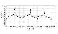
- FIG. 4 is a graph showing the relationship between the charge / discharge cycle time (sec) and the battery voltage (V) in the example system manufactured in Test Example 1.
- FIG. 5 is a graph showing the relationship between the charge / discharge cycle time (sec) and the battery voltage (V) in the example system produced in Test Example 4.
- FIG. 4 is a graph showing the relationship between the charge / discharge cycle time (sec) and the battery voltage (V) in the example system produced in Test Example 4.
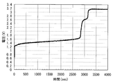
- FIG. 6 is a graph showing the relationship between the charging time (sec) of the comparison system (I) and the battery voltage (V).
- FIG. 7 is a graph showing the relationship between the charge / discharge cycle time (sec) of the comparison system (II) and the battery voltage (V).
- FIGS. 1 to 3 the same reference numerals indicate the same names.
- Metal ions other than vanadium ions shown in FIGS. 1 to 3 are examples.
- a solid line arrow indicates charging, and a broken line arrow indicates discharging.
- the redox flow battery 100 typically includes an AC / DC converter, a power generation unit (e.g., a solar power generator, a wind power generator, other general power plants, etc.) and a power system or a consumer. It is connected to a load, is charged using the power generation unit as a power supply source, and is discharged using the load as a power supply target.
- a circulation mechanism for circulating the electrolytic solution in the battery 100 is constructed.
- the redox flow battery 100 includes a positive electrode cell 102 including a positive electrode 104, a negative electrode cell 103 including a negative electrode 105, and a diaphragm 101 that separates the cells 102 and 103 and appropriately transmits ions.
- a positive electrode electrolyte tank 106 is connected to the positive electrode cell 102 via pipes 108 and 110.
- a negative electrode electrolyte tank 107 is connected to the negative electrode cell 103 via pipes 109 and 111.
- the pipes 108 and 109 include pumps 112 and 113 for circulating the electrolyte solution of each electrode.
- the redox flow battery 100 uses the pipes 108 to 111 and the pumps 112 and 113 to connect the positive electrode electrolyte in the tank 106 and the negative electrode electrolyte in the tank 107 to the positive electrode cell 102 (positive electrode 104) and the negative electrode cell 103 (negative electrode 105), respectively. Is charged and discharged along with the valence change reaction of the metal ions that become the active material in the electrolyte solution of each electrode.
- the redox flow battery 100 typically uses a form called a cell stack in which a plurality of the cells 102 and 103 are stacked.
- the cells 102 and 103 have a bipolar plate (not shown) in which the positive electrode 104 is disposed on one side and the negative electrode 105 is disposed on the other side, a liquid supply hole for supplying an electrolytic solution, and a drainage hole for discharging the electrolytic solution.
- a typical configuration is a cell frame including a frame (not shown) formed on the outer periphery of the bipolar plate. By laminating a plurality of cell frames, the liquid supply hole and the drainage hole constitute an electrolyte flow path, and the flow path is appropriately connected to the pipes 108 to 111.
- the cell stack is configured by repeatedly stacking a cell frame, a positive electrode 104, a diaphragm 101, a negative electrode 105, a cell frame,.
- a well-known structure can be utilized suitably for the basic structure of a redox flow battery system.
- both of the positive electrode electrolyte and the negative electrode electrolyte contain vanadium ions, and the positive electrode electrolyte is a metal having a higher potential than vanadium ions in addition to vanadium ions. It further contains ions (FIG. 1 shows manganese ions as an example).
- both of the positive electrode electrolyte and the negative electrode electrolyte contain vanadium ions, and the positive electrode electrolyte is a metal having a nobler potential than vanadium ions in addition to vanadium ions.
- the negative electrode electrolyte further contains metal ions having a lower potential than vanadium ions (in FIG. 2, examples include manganese ions as an example). As chromium ion).
- both of the positive electrode electrolyte and the negative electrode electrolyte contain vanadium ions, and the negative electrode electrolyte is a metal having a lower potential than vanadium ions in addition to vanadium ions. It further contains ions (FIG. 3 shows chromium ions as an example).
- the redox flow battery system shown in FIGS. 1 to 3 is constructed as a basic configuration, and various electrolytes containing vanadium ions are prepared on both the positive electrode and the negative electrode to satisfy various conditions. Discharge was performed.
- Carbon felt was used for the positive electrode and the negative electrode, and an ion exchange membrane was used for the diaphragm.
- the constituent material of an electrode or a diaphragm can be selected as appropriate.
- the electrode composed of carbon felt has the following effects: (1) Oxygen gas is hardly generated on the positive electrode side and hydrogen gas is not generated on the negative electrode side, (2) Large surface area, (3) Excellent electrolyte circulation .
- the ion exchange membrane has effects such as (1) excellent isolation of metal ions, which are active materials of each electrode, and (2) excellent permeability of H + ions (charge carriers inside the battery).
- Test Example 1 a small single cell battery having an electrode area of 9 cm 2 was prepared, and using the prepared electrolyte solution for each electrode, the current was 630 mA (current density: 70 mA / cm 2 ). Charging was performed at a constant current. More specifically, charging was performed until the state of charge (SOC) of vanadium ions in the positive electrode electrolyte corresponded to 124%.
- SOC state of charge
- the charge state is a numerical value when the case where only vanadium ions are used as an active material is 100, and the charge state is more than 100% in addition to the state of charge of vanadium ions being almost 100%, Mn 2+ changes to Mn 3+ (or tetravalent manganese), indicating that the battery is charged. Then, it switched to discharge and discharged, and also charge / discharge was repeated on the same charging conditions as the above.
- FIG. 4 shows the relationship between the charge / discharge cycle time and the battery voltage.
- comparison system an all-vanadium redox flow battery system was constructed.
- the basic configuration of the comparison system is the same as that of the above-described embodiment system, and is the same as that of the above-described embodiment system except that the electrolytic solution and the operating conditions are different.
- the positive electrode electrolyte and the negative electrode electrolyte the positive electrode: sulfuric acid aqueous solution having a sulfuric acid concentration of 2.6 M (H 2 SO 4 aq), vanadium sulfate (tetravalent), negative electrode: sulfuric acid aqueous solution having a sulfuric acid concentration of 1.75 M Dissolving vanadium sulfate (trivalent) in (H 2 SO 4 aq), the positive electrode: vanadium ion (tetravalent) concentration, and the negative electrode: vanadium ion (trivalent) concentration are all 1.7M vanadium electrolysis A liquid was prepared.
- FIG. 6 shows the relationship between the charging time of the comparison system (I) and the battery voltage.
- the comparative system (II) was the same as the comparative system (I) except that the amount of electrolyte and the operating conditions were different. Specifically, charging was performed at a constant current of 630 mA (current density: 70 mA / cm 2 ) using 7 ml (7 cc) of each of the above vanadium electrolytes for each of the positive electrode and the negative electrode. In the comparison system (II), when the voltage reached 1.6 V (vanadium ion charge state: 78%), the charge was stopped and switched to discharge, and the charge and discharge were repeated in the same manner.
- FIG. 7 shows the relationship between the charge / discharge cycle time of the comparative system (II) and the battery voltage.
- the discharge time (discharge capacity) of the example system was 23.7 minutes, 93.7% of the theoretical capacity (vanadium ion concentration: 1.65 M, 6 ml, converted from 630 mA to discharge time: 25.3 minutes), 90% The utilization rate was over%.
- the battery capacity did not decrease and the battery operated stably.
- At least the positive electrode electrolyte contains, in addition to vanadium ions, metal ions having a higher potential than the vanadium ions on the positive electrode side, thereby effectively increasing the utilization of vanadium ions and increasing energy. It can be said that the density can be improved.
- Test Example 2 As a positive electrode electrolyte, a sulfate: vanadium sulfate (tetravalent) and manganese sulfate (divalent) were dissolved in a sulfuric acid aqueous solution (H 2 SO 4 aq) having a sulfuric acid concentration of 2.6 M, and vanadium ions were dissolved. 6 ml (6 cc) of an electrolytic solution having a (tetravalent) concentration of 1.65 M and a manganese ion (divalent) concentration of 0.5 M was prepared.
- a sulfate: vanadium sulfate (trivalent) and manganese sulfate (divalent) are dissolved in a sulfuric acid aqueous solution (H 2 SO 4 aq) having a sulfuric acid concentration of 1.65 M, and vanadium ions (trivalent) are dissolved.
- 9 ml (9 cc) of an electrolyte solution having a concentration of 1.7M and a manganese ion (divalent) concentration of 0.5M was prepared.
- Other configurations were the same as those of the example system of Test Example 1.
- a small single-cell battery (electrode area: 9 cm 2 ) similar to that of Test Example 1 was prepared, and using the prepared electrolyte solution for each of the positive electrode and the negative electrode, conditions similar to those of the Example system of Test Example 1 were used.
- the behavior of the voltage characteristics of the system of Test Example 2 was almost the same as that of the Example system of Test Example 1, and the utilization rate could be increased to more than 90%.
- the generation of oxygen gas was not observed in the system of Test Example 2 and that the electrode was not deteriorated even when the cell was disassembled after repeated charge and discharge.
- vanadium sulfate (trivalent), manganese sulfate (divalent), and chromium sulfate (trivalent) are dissolved in a sulfuric acid aqueous solution (H 2 SO 4 aq) having a sulfuric acid concentration of 1.75M, and vanadium is dissolved.
- 6 ml (6 cc) of an electrolyte solution having an ion (trivalent) concentration of 1.65 M, a manganese ion (divalent) concentration of 0.5 M, and a chromium ion (trivalent) concentration of 0.1 M was prepared.
- Carbon felt was used for the positive electrode and the negative electrode, and an ion exchange membrane was used for the diaphragm.
- the charge state is a numerical value when the case where only vanadium ions are used as an active material is 100, and the charge state is more than 100% in addition to the state of charge of vanadium ions being almost 100%.
- Mn 2+ is changed to Mn 3+ (or tetravalent manganese) and charged
- Cr 3+ is changed to Cr 2+ to be charged. Then, it switched to discharge and discharged, and also charge / discharge was repeated on the same charging conditions as the above.
- the comparison system was the comparison system (I) and the comparison system (II) of Test Example 1.
- the discharge time (discharge capacity) of the example system of Embodiment 2 is more than 90% utilization relative to the theoretical capacity (vanadium ion concentration: 1.65M, 6 ml, value converted to discharge time from 630 mA: 25.3 minutes). It was confirmed that it was a rate. In addition, it was confirmed that even if charging / discharging was repeated, the battery capacity did not decrease and the battery operated stably.
- At least the positive electrode electrolyte solution contains metal ions having a potential higher than the vanadium ion on the positive electrode side, or at least the negative electrode electrolyte solution contains vanadium ions and the negative electrode side. It can be said that the energy density can be improved by effectively increasing the utilization of vanadium ions by containing metal ions having a base potential lower than that of vanadium ions.
- the metal ion species in the electrolyte solution of both the positive electrode and the negative electrode are duplicated, so that (1) the metal ions as the active material are relatively less likely to decrease, and side reactions occur. It can be said that (2) it is easy to correct variations in the amount of liquid due to liquid transfer, and (3) it is excellent in electrolyte productivity.
- the battery reaction on the negative electrode side (including not only the reduction reaction of vanadium ions but also the reduction reaction of chromium ions) can be sufficiently performed during charging. (This also applies to Test Example 5 described later). Carbon felt was used for the positive electrode and the negative electrode, and an ion exchange membrane was used for the diaphragm.
- Test Example 4 a small single cell battery having an electrode area of 9 cm 2 was prepared, and using the prepared electrolyte solution for each electrode, the current was 630 mA (current density: 70 mA / cm 2 ). Charging was performed at a constant current. More specifically, charging was performed until the state of charge (SOC) of vanadium ions in the negative electrode electrolyte was 109%.
- SOC state of charge
- the charge state is a numerical value when the case where only vanadium ions are used as an active material is 100, and the charge state is more than 100% in addition to the state of charge of vanadium ions being almost 100%, This shows that Cr 3+ is changed to Cr 2+ to be charged.
- FIG. 5 shows the relationship between the charge / discharge cycle time and the battery voltage.
- the comparison system was the comparison system (I) and the comparison system (II) of Test Example 1.
- the discharge time (discharge capacity) of the example system of Embodiment 3 is 25.9 minutes, and 99.6% of the theoretical capacity (vanadium ion concentration: 1.75 M, 6 ml, value converted to discharge time from 630 mA: 26 minutes). A capacity of nearly 100% was obtained, and the utilization rate exceeded 90%. Moreover, although charging / discharging was performed repeatedly, it was confirmed that there is no decrease in battery capacity and the operation is stable.
- At least the negative electrode electrolyte contains, in addition to vanadium ions, metal ions having a lower potential than vanadium ions on the negative electrode side, thereby effectively increasing the utilization rate of vanadium ions and energy. It can be said that the density can be improved.
- Test Example 5 an electrolyte solution containing vanadium ions and chromium ions was used as the electrolyte solution for both the positive electrode and the negative electrode.
- a positive electrode electrolyte the same raw materials as in the Example system of Test Example 4, further prepared sulfate: chromium sulfate (trivalent), vanadium ion (tetravalent) concentration: 1.7M, Chromium ion (trivalent) concentration: 9 ml (9 cc) of 0.1M electrolyte was prepared.
- the negative electrode electrolyte solution was the same as that of the example system of Test Example 4 (vanadium ion (trivalent) concentration: 1.7 M, chromium ion (trivalent) concentration: 0.1 M, 6 ml (6 cc)).
- Other configurations were the same as those of the example system of Test Example 4.
- the present invention is not limited to the above-described embodiment, and can be appropriately changed without departing from the gist of the present invention.
- the type and concentration of metal ions, the concentration of the solvent of the electrolytic solution, and the like can be changed as appropriate.
- the redox flow battery of the present invention has a large capacity for the purpose of stabilizing fluctuations in power generation output, storing electricity when surplus of generated power, load leveling, etc., for power generation of new energy such as solar power generation and wind power generation. It can utilize suitably for a storage battery.
- the redox flow battery of the present invention can be suitably used as a large-capacity storage battery that is provided in a general power plant and is intended for measures against instantaneous voltage drop / power outage and load leveling.
- Redox flow battery 101 Diaphragm 102 Positive electrode cell 103 Negative electrode cell 104 Positive electrode 105 Negative electrode 106 Tank for positive electrolyte 107 Tank for negative electrolyte 108,109,110,111 Piping 112,113 Pump
Landscapes
- Chemical & Material Sciences (AREA)
- Chemical Kinetics & Catalysis (AREA)
- Electrochemistry (AREA)
- General Chemical & Material Sciences (AREA)
- Life Sciences & Earth Sciences (AREA)
- Engineering & Computer Science (AREA)
- Manufacturing & Machinery (AREA)
- Sustainable Development (AREA)
- Sustainable Energy (AREA)
- Fuel Cell (AREA)
- Battery Electrode And Active Subsutance (AREA)
- Secondary Cells (AREA)
Abstract
Description
充電(正極):V4+→V5++e- 電位:約1.0V(V4+/V5+)
充電(負極):V3++e-→V2+ 電位:約-0.26V(V3+/V2+)
充電(正極) H2O→(1/2)O2+2H++2e- 電位:約1.2V(実際の電位:約2.0V)
C(カーボン)+O2→CO2+4e- 電位:約1.2V(実際の電位:約2.0V)
充電(負極) H++e-→(1/2)H2 電位:約0V(実際の電位:約-0.5V)
(2) 正極電解液及び負極電解液のいずれもが、バナジウムイオンと、バナジウムイオンよりも貴な電位の金属イオンとを含む形態
(3) 少なくとも正極電解液は、バナジウムイオンと、バナジウムイオンよりも貴な電位の金属イオンと、バナジウムイオンよりも卑な電位の金属イオンとを含み、負極電解液は、バナジウムイオンを含む形態
(4) 少なくとも正極電解液は、バナジウムイオンと、バナジウムイオンよりも貴な電位の金属イオンと、バナジウムイオンよりも卑な電位の金属イオンとを含み、少なくとも負極電解液は、バナジウムイオンと、バナジウムイオンよりも貴な電位の金属イオンとを含む形態
(5) 正極電解液は、バナジウムイオンを含み、少なくとも負極電解液は、バナジウムイオンと、バナジウムイオンよりも卑な電位の金属イオンとを含む形態
(6) 正極電解液及び負極電解液のいずれもが、バナジウムイオンと、バナジウムイオンよりも卑な電位の金属イオンとを含む形態
(7) 正極電解液は、バナジウムイオンを含み、少なくとも負極電解液は、バナジウムイオンと、バナジウムイオンよりも貴な電位の金属イオンと、バナジウムイオンよりも卑な電位の金属イオンとを含む形態
(8) 少なくとも正極電解液は、バナジウムイオンと、バナジウムイオンよりも卑な電位の金属イオンとを含み、少なくとも負極電解液は、バナジウムイオンと、バナジウムイオンよりも貴な電位の金属イオンと、バナジウムイオンよりも卑な電位の金属イオンとを含む形態
実施形態1の実施例システムとして、以下を用意した。
(電解液)
正極電解液として、硫酸濃度が2.6Mの硫酸水溶液(H2SO4aq)に、硫酸塩:硫酸バナジウム(4価)及び硫酸マンガン(2価)を溶解して、バナジウムイオン(4価)の濃度が1.65M、マンガンイオン(2価)の濃度が0.5Mの電解液を6ml(6cc)作製した。
負極電解液として、硫酸濃度が1.75Mの硫酸水溶液(H2SO4aq)に硫酸塩:硫酸バナジウム(3価)を溶解して、バナジウムイオン(3価)の濃度が1.7Mの電解液を9ml(9cc)作製した。負極電解液の量を正極電解液の量よりも多くすることで、充電時に正極側での電池反応(バナジウムイオンの酸化反応だけでなくマンガンイオンの酸化反応も含む)が十分に行えるようにしている(この点は、後述する試験例2も同様である)。
正極及び負極の各極の電極には、カーボンフェルト、隔膜には、イオン交換膜を用いた。電極や隔膜の構成材料は適宜選択することができる。カーボンフェルトから構成される電極は、(1)正極側で酸素ガス及び負極側で水素ガスが発生し難い、(2)表面積が大きい、(3)電解液の流通性に優れる、といった効果がある。イオン交換膜は、(1)各極の活物質である金属イオンの隔離性に優れる、(2)H+イオン(電池内部の電荷担体)の透過性に優れる、といった効果がある。
試験例2では、正極電解液として、硫酸濃度が2.6Mの硫酸水溶液(H2SO4aq)に、硫酸塩:硫酸バナジウム(4価)及び硫酸マンガン(2価)を溶解して、バナジウムイオン(4価)の濃度が1.65M、マンガンイオン(2価)の濃度が0.5Mの電解液を6ml(6cc)作製した。負極電解液として、硫酸濃度が1.65Mの硫酸水溶液(H2SO4aq)に、硫酸塩:硫酸バナジウム(3価)及び硫酸マンガン(2価)を溶解して、バナジウムイオン(3価)の濃度が1.7M、マンガンイオン(2価)の濃度が0.5Mの電解液を9ml(9cc)作製した。その他の構成は、試験例1の実施例システムと同様とした。
実施形態2の実施例システムとして、以下を用意した。
正極電解液として、硫酸濃度が2.6Mの硫酸水溶液(H2SO4aq)に、硫酸塩:硫酸バナジウム(4価)、硫酸マンガン(2価)、硫酸クロム(3価)を溶解して、バナジウムイオン(4価)の濃度が1.65M、マンガンイオン(2価)の濃度が0.5M、クロムイオン(3価)の濃度が0.1Mの電解液を6ml(6cc)作製した。
負極電解液として、硫酸濃度が1.75Mの硫酸水溶液(H2SO4aq)に硫酸塩:硫酸バナジウム(3価)、硫酸マンガン(2価)、硫酸クロム(3価)を溶解して、バナジウムイオン(3価)の濃度が1.65M、マンガンイオン(2価)の濃度が0.5M、クロムイオン(3価)の濃度が0.1Mの電解液を6ml(6cc)作製した。
正極及び負極の各極の電極には、カーボンフェルト、隔膜には、イオン交換膜を用いた。
実施形態3の実施例システムとして、以下を用意した。
正極電解液として、硫酸濃度が2.6Mの硫酸水溶液(H2SO4aq)に、硫酸塩:硫酸バナジウム(4価)を溶解して、バナジウムイオン(4価)の濃度が1.7Mの電解液を9ml(9cc)作製した。
負極電解液として、硫酸濃度が1.75Mの硫酸水溶液(H2SO4aq)に硫酸塩:硫酸バナジウム(3価)及び硫酸クロム(3価)を溶解して、バナジウムイオン(3価)の濃度が1.7M、クロムイオン(3価)の濃度が0.1Mの電解液を6ml(6cc)作製した。正極電解液の量を負極電解液の量よりも多くすることで、充電時に負極側での電池反応(バナジウムイオンの還元反応だけでなくクロムイオンの還元反応も含む)が十分に行えるようにしている(この点は、後述する試験例5も同様である)。
正極及び負極の各極の電極には、カーボンフェルト、隔膜には、イオン交換膜を用いた。
試験例5では、正極及び負極の両極の電解液として、バナジウムイオンとクロムイオンとを含有する電解液を用いた。具体的には、正極電解液として、試験例4の実施例システムと同様の原料に、更に硫酸塩:硫酸クロム(3価)を用意して、バナジウムイオン(4価)の濃度:1.7M、クロムイオン(3価)の濃度:0.1Mの電解液を9ml(9cc)作製した。負極電解液は、試験例4の実施例システムと同様のもの(バナジウムイオン(3価)の濃度:1.7M、クロムイオン(3価)の濃度:0.1M、6ml(6cc))を用意した。その他の構成は、試験例4の実施例システムと同様とした。
104 正極電極 105 負極電極 106 正極電解液用のタンク
107 負極電解液用のタンク 108,109,110,111 配管 112,113 ポンプ
Claims (18)
- 電池セルに正極電解液及び負極電解液を供給して充放電を行うレドックスフロー電池であって、
前記正極電解液及び前記負極電解液はいずれも、バナジウムイオンを含有し、
前記正極電解液及び前記負極電解液の少なくとも一方は、バナジウムイオンよりも貴な電位の金属イオン及びバナジウムイオンよりも卑な電位の金属イオンの少なくとも一方を更に含有することを特徴とするレドックスフロー電池。 - 少なくとも前記正極電解液は、バナジウムイオンよりも貴な電位の金属イオンを更に含有することを特徴とする請求項1に記載のレドックスフロー電池。
- 前記正極電解液及び前記負極電解液はいずれも、バナジウムイオンよりも貴な電位の金属イオンを更に含有することを特徴とする請求項1に記載のレドックスフロー電池。
- 前記貴な電位の金属イオンは、マンガンイオン、鉛イオン、セリウムイオン、及びコバルトイオンから選択される少なくとも1種の金属イオンであり、
前記貴な電位の金属イオンを含む電解液中における当該貴な電位の金属イオンの合計濃度が0.1M以上5M以下であることを特徴とする請求項1~3のいずれか1項に記載のレドックスフロー電池。 - 前記貴な電位の金属イオンは、2価のマンガンイオン及び3価のマンガンイオンの少なくとも一種のマンガンイオンであることを特徴とする請求項1~4のいずれか1項に記載のレドックスフロー電池。
- 前記貴な電位の金属イオンを含む電解液は、2価のマンガンイオン、3価のマンガンイオンの少なくとも一種のマンガンイオンと、4価のマンガンとを含むことを特徴とする請求項1~4のいずれか1項に記載のレドックスフロー電池。
- 少なくとも前記正極電解液は、バナジウムイオンよりも貴な電位の金属イオンを更に含有し、
かつ、少なくとも前記負極電解液は、バナジウムイオンよりも卑な電位の金属イオンを更に含有することを特徴とする請求項1に記載のレドックスフロー電池。 - 前記正極電解液及び前記負極電解液の少なくとも一方は、バナジウムイオンよりも貴な電位の金属イオン及びバナジウムイオンよりも卑な電位の金属イオンの双方を更に含有することを特徴とする請求項1又は7に記載のレドックスフロー電池。
- 前記貴な電位の金属イオンは、マンガンイオン、鉛イオン、セリウムイオン、及びコバルトイオンから選択される少なくとも1種の金属イオンであり、
前記卑な電位の金属イオンは、クロムイオン及び亜鉛イオンの少なくとも1種の金属イオンであり、
前記貴な電位の金属イオンを含む電解液中における当該貴な金属イオンの合計濃度、及び前記卑な電位の金属イオンを含む電解液中における当該卑な金属イオンの合計濃度がいずれも0.1M以上5M以下であることを特徴とする請求項1,7及び8のいずれか1項に記載のレドックスフロー電池。 - 前記貴な電位の金属イオンは、2価のマンガンイオン及び3価のマンガンイオンの少なくとも一種のマンガンイオンであり、
前記卑な電位の金属イオンは、2価のクロムイオン及び3価のクロムイオンの少なくとも一種のクロムイオンであることを特徴とする請求項1,7,8及び9のいずれか1項に記載のレドックスフロー電池。 - 前記貴な電位の金属イオンを含む電解液は、2価のマンガンイオン、3価のマンガンイオンの少なくとも一種のマンガンイオンと、4価のマンガンとを含み、
前記卑な電位の金属イオンは、2価のクロムイオン及び3価のクロムイオンの少なくとも一種のクロムイオンであることを特徴とする請求項1,7,8及び9のいずれか1項に記載のレドックスフロー電池。 - 少なくとも前記負極電解液は、バナジウムイオンよりも卑な電位の金属イオンを更に含有することを特徴とする請求項1に記載のレドックスフロー電池。
- 前記正極電解液及び前記負極電解液はいずれも、バナジウムイオンよりも卑な電位の金属イオンを更に含有することを特徴とする請求項1に記載のレドックスフロー電池。
- 前記卑な電位の金属イオンは、クロムイオン及び亜鉛イオンの少なくとも1種の金属イオンであり、
前記卑な電位の金属イオンを含む電解液中における当該卑な電位の金属イオンの合計濃度が0.1M以上5M以下であることを特徴とする請求項1,12及び13のいずれか1項に記載のレドックスフロー電池。 - 前記卑な電位の金属イオンは、2価のクロムイオン及び3価のクロムイオンの少なくとも一種のクロムイオンであることを特徴とする請求項1,12,13及び14のいずれか1項に記載のレドックスフロー電池。
- 前記正極電解液及び前記負極電解液はいずれも、硫酸アニオンを含有することを特徴とする請求項1~15のいずれか1項に記載のレドックスフロー電池。
- 前記正極電解液及び前記負極電解液の溶媒は、H2SO4の水溶液であり、
前記正極電解液及び前記負極電解液の硫酸濃度がいずれも5M以下であることを特徴とする請求項1~16のいずれか1項に記載のレドックスフロー電池。 - 前記貴な電位の金属イオン及び前記卑な電位の金属イオンの少なくとも一方を含む極の電解液の充電状態が90%超となるように運転されることを特徴とする請求項1~17のいずれか1項に記載のレドックスフロー電池。
Priority Applications (11)
| Application Number | Priority Date | Filing Date | Title |
|---|---|---|---|
| US13/505,281 US8771857B2 (en) | 2010-04-27 | 2011-04-27 | Redox flow battery |
| DK11775037.2T DK2485312T3 (da) | 2010-04-27 | 2011-04-27 | Redox-flow-batteri |
| AU2011246147A AU2011246147B9 (en) | 2010-04-27 | 2011-04-27 | Redox flow battery |
| KR1020127012392A KR20120132620A (ko) | 2010-04-27 | 2011-04-27 | 레독스 플로우 전지 |
| ES11775037T ES2429359T3 (es) | 2010-04-27 | 2011-04-27 | Batería de flujo redox |
| KR1020127012072A KR101178327B1 (ko) | 2010-04-27 | 2011-04-27 | 레독스 플로우 전지 |
| CN2011800045859A CN102652377B (zh) | 2010-04-27 | 2011-04-27 | 氧化还原液流电池 |
| EP11775037.2A EP2485312B1 (en) | 2010-04-27 | 2011-04-27 | Redox flow battery |
| CA2781582A CA2781582C (en) | 2010-04-27 | 2011-04-27 | Redox flow battery |
| US13/472,943 US20120282509A1 (en) | 2010-04-27 | 2012-05-16 | Redox flow battery |
| ZA2012/03785A ZA201203785B (en) | 2010-04-27 | 2012-05-23 | Redox flow battery |
Applications Claiming Priority (6)
| Application Number | Priority Date | Filing Date | Title |
|---|---|---|---|
| JP2010102748A JP2011233372A (ja) | 2010-04-27 | 2010-04-27 | レドックスフロー電池 |
| JP2010102749A JP2011233373A (ja) | 2010-04-27 | 2010-04-27 | レドックスフロー電池 |
| JP2010-102747 | 2010-04-27 | ||
| JP2010102747A JP4863172B2 (ja) | 2010-04-27 | 2010-04-27 | レドックスフロー電池 |
| JP2010-102749 | 2010-04-27 | ||
| JP2010-102748 | 2010-04-27 |
Related Child Applications (1)
| Application Number | Title | Priority Date | Filing Date |
|---|---|---|---|
| US13/472,943 Continuation US20120282509A1 (en) | 2010-04-27 | 2012-05-16 | Redox flow battery |
Publications (1)
| Publication Number | Publication Date |
|---|---|
| WO2011136256A1 true WO2011136256A1 (ja) | 2011-11-03 |
Family
ID=44861554
Family Applications (1)
| Application Number | Title | Priority Date | Filing Date |
|---|---|---|---|
| PCT/JP2011/060228 Ceased WO2011136256A1 (ja) | 2010-04-27 | 2011-04-27 | レドックスフロー電池 |
Country Status (10)
| Country | Link |
|---|---|
| US (2) | US8771857B2 (ja) |
| EP (2) | EP2581976B1 (ja) |
| KR (2) | KR101178327B1 (ja) |
| CN (2) | CN102652377B (ja) |
| CA (1) | CA2781582C (ja) |
| DK (2) | DK2581976T3 (ja) |
| ES (2) | ES2429359T3 (ja) |
| TW (2) | TW201230482A (ja) |
| WO (1) | WO2011136256A1 (ja) |
| ZA (1) | ZA201203785B (ja) |
Cited By (9)
| Publication number | Priority date | Publication date | Assignee | Title |
|---|---|---|---|---|
| US8785023B2 (en) | 2008-07-07 | 2014-07-22 | Enervault Corparation | Cascade redox flow battery systems |
| US8906529B2 (en) | 2008-07-07 | 2014-12-09 | Enervault Corporation | Redox flow battery system for distributed energy storage |
| US8916281B2 (en) | 2011-03-29 | 2014-12-23 | Enervault Corporation | Rebalancing electrolytes in redox flow battery systems |
| WO2015019973A1 (ja) * | 2013-08-07 | 2015-02-12 | 住友電気工業株式会社 | レドックスフロー電池 |
| WO2015019974A1 (ja) * | 2013-08-07 | 2015-02-12 | 住友電気工業株式会社 | レドックスフロー電池 |
| US8980484B2 (en) | 2011-03-29 | 2015-03-17 | Enervault Corporation | Monitoring electrolyte concentrations in redox flow battery systems |
| US8980454B2 (en) | 2013-03-15 | 2015-03-17 | Enervault Corporation | Systems and methods for rebalancing redox flow battery electrolytes |
| JP2016507152A (ja) * | 2013-02-14 | 2016-03-07 | ハイドラレドックス テクノロジーズ ホールディングス リミテッド | 正電解液においてV+4/V+5レドックス対及び補助Ce+3/Ce+4レドックス対を使用した全バナジウムレドックスフロー電池システム |
| WO2025192118A1 (ja) * | 2024-03-15 | 2025-09-18 | 住友電気工業株式会社 | レドックスフロー電池システム、およびレドックスフロー電池の運転方法 |
Families Citing this family (32)
| Publication number | Priority date | Publication date | Assignee | Title |
|---|---|---|---|---|
| CN102881932B (zh) * | 2012-09-26 | 2015-04-15 | 清华大学 | 一种含锰的钒液流电池电解液 |
| KR101382031B1 (ko) * | 2012-11-15 | 2014-04-04 | 성균관대학교산학협력단 | 알루미늄―공기 연료 전지용 전해액 및 이를 포함한 알루미늄―공기 연료 전지 |
| CN103022543A (zh) * | 2012-12-20 | 2013-04-03 | 中国科学院长春应用化学研究所 | 一种铈铅液流电池 |
| CN104143660B (zh) * | 2013-05-09 | 2017-02-08 | 中国科学院大连化学物理研究所 | 一种铅酸‑全钒混合储能电池 |
| AU2014303614B2 (en) * | 2013-08-07 | 2017-09-14 | Sumitomo Electric Industries, Ltd. | Redox flow battery |
| WO2015054878A1 (zh) * | 2013-10-18 | 2015-04-23 | 中国电力科学研究院 | 基于变化率控制储能电站平滑风光发电波动的方法及系统 |
| TWI506292B (zh) * | 2013-10-28 | 2015-11-01 | Inst Nuclear Energy Res Atomic Energy Council | 超音波檢測液流電池充放電狀態裝置 |
| KR101558079B1 (ko) | 2014-02-20 | 2015-10-06 | 오씨아이 주식회사 | 레독스 흐름 전지 |
| KR101653765B1 (ko) | 2014-05-26 | 2016-09-02 | 롯데케미칼 주식회사 | 레독스 흐름 전지용 양극 전해질 제조 방법 및 레독스 흐름 전지 |
| CN105322186B (zh) * | 2014-07-30 | 2018-06-19 | 中国科学院大连化学物理研究所 | 一种减小全钒液流电池电化学极化的方法 |
| KR20160051476A (ko) | 2014-11-03 | 2016-05-11 | 삼성에스디아이 주식회사 | 이차 전지 및 이를 포함하는 이차 전지 팩 |
| KR20160097491A (ko) | 2015-02-09 | 2016-08-18 | (주)아이디알 | 약제 희석기능을 갖는 휴대용 분무기 |
| WO2016163773A1 (ko) * | 2015-04-08 | 2016-10-13 | 주식회사 엘지화학 | 고분자 전해질막, 이를 포함하는 전기화학 전지 및 흐름전지, 고분자 전해질막의 제조방법 및 흐름 전지용 전해액 |
| DE102015014828A1 (de) * | 2015-11-18 | 2017-05-18 | Friedrich-Schiller-Universität Jena | Hybrid-Flow-Zelle zur Speicherung elektrischer Energie und deren Verwendung |
| JP6775300B2 (ja) * | 2016-02-10 | 2020-10-28 | 住友電気工業株式会社 | レドックスフロー電池用電極、及びレドックスフロー電池 |
| FR3052924B1 (fr) * | 2016-06-21 | 2019-08-09 | Kemiwatt | Dispositif de protection contre la surcharge electrique pour accumulateur electrochimique |
| CN109643818A (zh) * | 2016-09-02 | 2019-04-16 | 昭和电工株式会社 | 氧化还原流动二次电池及其电极 |
| AU2018246134A1 (en) * | 2017-03-27 | 2019-11-14 | Carlo Alberto BROVERO | Novel leaks containment embodiment for electrochemical stack |
| WO2019031033A1 (ja) * | 2017-08-10 | 2019-02-14 | 京セラ株式会社 | フロー電池 |
| KR20190058136A (ko) * | 2017-11-21 | 2019-05-29 | 롯데케미칼 주식회사 | 레독스 흐름전지용 전해액 및 이를 포함하는 레독스 흐름전지 |
| CN108258292A (zh) * | 2018-03-29 | 2018-07-06 | 四川大学 | 一种全钒液流电池正极电解液及其配置方法 |
| CN109659588A (zh) * | 2018-12-10 | 2019-04-19 | 合肥沃工电气自动化有限公司 | 一种钒电池自启动运行控制方法 |
| NL2022980B1 (nl) | 2019-04-18 | 2020-10-26 | Lamaxan Holding B V | Een energie-opslag-ponton, een schip, een scheepvaartsysteem en een werkwijze voor het bedrijven van het scheepvaartsystem. |
| CN110911704A (zh) * | 2019-11-26 | 2020-03-24 | 中国科学院金属研究所 | 一种铁铬液流电池电解液及其应用 |
| CN110912198B (zh) * | 2019-12-17 | 2021-10-01 | 陈翔 | 一种应用于智能家居的自动化控制系统及控制方法 |
| IL316996A (en) * | 2022-05-27 | 2025-01-01 | Green Energy Storage S R L | REDOX FLOW BATTERY |
| KR102818903B1 (ko) * | 2022-07-19 | 2025-06-11 | 서울과학기술대학교 산학협력단 | 레독스 흐름 전지의 가속 수명 평가 방법 |
| CN115642278A (zh) * | 2022-09-15 | 2023-01-24 | 大连融科储能集团股份有限公司 | 一种钒铬电解液、其制备方法及由其构成的液流电池 |
| CN116799272A (zh) * | 2023-02-21 | 2023-09-22 | 沈阳恒久安泰环保与节能科技有限公司 | 3.5价硫酸体系钒电解液及其制备方法和电池 |
| CN119812419B (zh) * | 2025-03-13 | 2025-07-01 | 浙江师范大学 | 一种锰正极沉积/溶解胶体电解液及其应用 |
| CN120878892B (zh) * | 2025-09-26 | 2025-12-02 | 中国电气装备集团科学技术研究院有限公司 | 基于外加电场抑制离子迁移的液流电池系统及其抑制方法 |
| CN121394480A (zh) * | 2025-12-25 | 2026-01-23 | 天津大学 | 一种水系全铬液流电池电解液、制备方法与包含其的电池 |
Citations (10)
| Publication number | Priority date | Publication date | Assignee | Title |
|---|---|---|---|---|
| JPS579073A (en) * | 1980-06-17 | 1982-01-18 | Agency Of Ind Science & Technol | Bedox battery |
| JPS611270U (ja) * | 1984-06-11 | 1986-01-07 | 住友電気工業株式会社 | 電池 |
| JPS6122574A (ja) * | 1984-07-09 | 1986-01-31 | Sumitomo Electric Ind Ltd | 電池 |
| JPH0279374A (ja) * | 1988-09-14 | 1990-03-19 | Agency Of Ind Science & Technol | 教材用レドックス電地 |
| JPH0419966A (ja) * | 1990-05-11 | 1992-01-23 | Agency Of Ind Science & Technol | レドックス電池 |
| JPH11204124A (ja) * | 1998-01-08 | 1999-07-30 | Sumitomo Electric Ind Ltd | 電解液流通型電池 |
| JP3143568B2 (ja) | 1994-11-08 | 2001-03-07 | 住友電気工業株式会社 | レドックスフロー電池の運転方法 |
| JP2002175831A (ja) * | 2000-09-29 | 2002-06-21 | Shinko Kagaku Kogyo Kk | バナジウムレドックスフロー電池用電解液の製造方法 |
| JP2003157884A (ja) | 2001-11-21 | 2003-05-30 | Sumitomo Electric Ind Ltd | バナジウムレドックスフロー電池の充電方法 |
| JP2006147374A (ja) * | 2004-11-19 | 2006-06-08 | Kansai Electric Power Co Inc:The | バナジウムレドックスフロー電池システムの運転方法 |
Family Cites Families (14)
| Publication number | Priority date | Publication date | Assignee | Title |
|---|---|---|---|---|
| US4362791A (en) | 1980-06-17 | 1982-12-07 | Agency Of Industrial Science & Technology | Redox battery |
| JPS62216176A (ja) | 1986-03-15 | 1987-09-22 | Agency Of Ind Science & Technol | レドツクス電池用電解液 |
| JPH04149965A (ja) * | 1990-10-15 | 1992-05-22 | Agency Of Ind Science & Technol | バナジウム系電解液の製造方法 |
| US5318865A (en) * | 1991-06-06 | 1994-06-07 | Director-General, Agency Of Industrial Science And Technology | Redox battery |
| JPH09507950A (ja) * | 1993-11-17 | 1997-08-12 | ユニサーチ リミテッド | 安定電解液およびその製造方法と、レドックス電池の製造方法、および安定した電解液を含む電池 |
| CA2220075C (en) | 1995-05-03 | 2008-07-08 | Unisearch Limited | High energy density vanadium electrolyte solutions, methods of preparation thereof and all-vanadium redox cells and batteries containing high energy vanadium electrolyte solutions |
| US6085015A (en) * | 1997-03-25 | 2000-07-04 | Hydro-Quebec | Lithium insertion electrode materials based on orthosilicate derivatives |
| US7560189B2 (en) | 2001-08-10 | 2009-07-14 | Plurion Limited | Mixed electrolyte battery |
| AUPS192102A0 (en) | 2002-04-23 | 2002-05-30 | Unisearch Limited | Vanadium bromide redox flow battery |
| JP4804126B2 (ja) | 2005-11-25 | 2011-11-02 | 三菱電機株式会社 | 圧力センサ |
| GB0614338D0 (en) * | 2006-07-19 | 2006-08-30 | Acal Energy Ltd | Fuel cells |
| CN101593841B (zh) | 2008-05-30 | 2012-05-30 | 比亚迪股份有限公司 | 一种氧化还原液流电池和氧化还原液流电池组 |
| CN101635363B (zh) | 2008-07-27 | 2012-05-30 | 比亚迪股份有限公司 | 一种全钒离子液流电池电解液及其制备方法及电池 |
| DE102009009357B4 (de) | 2009-02-18 | 2011-03-03 | Fraunhofer-Gesellschaft zur Förderung der angewandten Forschung e.V. | Redox-Flow-Batterie zur Speicherung von elektrischer Energie in ionischen Flüssigkeiten |
-
2011
- 2011-04-27 ES ES11775037T patent/ES2429359T3/es active Active
- 2011-04-27 KR KR1020127012072A patent/KR101178327B1/ko active Active
- 2011-04-27 CN CN2011800045859A patent/CN102652377B/zh not_active Expired - Fee Related
- 2011-04-27 WO PCT/JP2011/060228 patent/WO2011136256A1/ja not_active Ceased
- 2011-04-27 TW TW100114630A patent/TW201230482A/zh not_active IP Right Cessation
- 2011-04-27 ES ES13151059.6T patent/ES2458490T3/es active Active
- 2011-04-27 DK DK13151059.6T patent/DK2581976T3/da active
- 2011-04-27 KR KR1020127012392A patent/KR20120132620A/ko not_active Withdrawn
- 2011-04-27 CN CN2012102543060A patent/CN102790234A/zh active Pending
- 2011-04-27 US US13/505,281 patent/US8771857B2/en active Active
- 2011-04-27 EP EP13151059.6A patent/EP2581976B1/en active Active
- 2011-04-27 EP EP11775037.2A patent/EP2485312B1/en active Active
- 2011-04-27 CA CA2781582A patent/CA2781582C/en active Active
- 2011-04-27 DK DK11775037.2T patent/DK2485312T3/da active
- 2011-04-27 TW TW101118964A patent/TW201246682A/zh unknown
-
2012
- 2012-05-16 US US13/472,943 patent/US20120282509A1/en not_active Abandoned
- 2012-05-23 ZA ZA2012/03785A patent/ZA201203785B/en unknown
Patent Citations (10)
| Publication number | Priority date | Publication date | Assignee | Title |
|---|---|---|---|---|
| JPS579073A (en) * | 1980-06-17 | 1982-01-18 | Agency Of Ind Science & Technol | Bedox battery |
| JPS611270U (ja) * | 1984-06-11 | 1986-01-07 | 住友電気工業株式会社 | 電池 |
| JPS6122574A (ja) * | 1984-07-09 | 1986-01-31 | Sumitomo Electric Ind Ltd | 電池 |
| JPH0279374A (ja) * | 1988-09-14 | 1990-03-19 | Agency Of Ind Science & Technol | 教材用レドックス電地 |
| JPH0419966A (ja) * | 1990-05-11 | 1992-01-23 | Agency Of Ind Science & Technol | レドックス電池 |
| JP3143568B2 (ja) | 1994-11-08 | 2001-03-07 | 住友電気工業株式会社 | レドックスフロー電池の運転方法 |
| JPH11204124A (ja) * | 1998-01-08 | 1999-07-30 | Sumitomo Electric Ind Ltd | 電解液流通型電池 |
| JP2002175831A (ja) * | 2000-09-29 | 2002-06-21 | Shinko Kagaku Kogyo Kk | バナジウムレドックスフロー電池用電解液の製造方法 |
| JP2003157884A (ja) | 2001-11-21 | 2003-05-30 | Sumitomo Electric Ind Ltd | バナジウムレドックスフロー電池の充電方法 |
| JP2006147374A (ja) * | 2004-11-19 | 2006-06-08 | Kansai Electric Power Co Inc:The | バナジウムレドックスフロー電池システムの運転方法 |
Non-Patent Citations (1)
| Title |
|---|
| See also references of EP2485312A4 |
Cited By (12)
| Publication number | Priority date | Publication date | Assignee | Title |
|---|---|---|---|---|
| US8785023B2 (en) | 2008-07-07 | 2014-07-22 | Enervault Corparation | Cascade redox flow battery systems |
| US8906529B2 (en) | 2008-07-07 | 2014-12-09 | Enervault Corporation | Redox flow battery system for distributed energy storage |
| US8916281B2 (en) | 2011-03-29 | 2014-12-23 | Enervault Corporation | Rebalancing electrolytes in redox flow battery systems |
| US8980484B2 (en) | 2011-03-29 | 2015-03-17 | Enervault Corporation | Monitoring electrolyte concentrations in redox flow battery systems |
| JP2016507152A (ja) * | 2013-02-14 | 2016-03-07 | ハイドラレドックス テクノロジーズ ホールディングス リミテッド | 正電解液においてV+4/V+5レドックス対及び補助Ce+3/Ce+4レドックス対を使用した全バナジウムレドックスフロー電池システム |
| US8980454B2 (en) | 2013-03-15 | 2015-03-17 | Enervault Corporation | Systems and methods for rebalancing redox flow battery electrolytes |
| WO2015019973A1 (ja) * | 2013-08-07 | 2015-02-12 | 住友電気工業株式会社 | レドックスフロー電池 |
| WO2015019974A1 (ja) * | 2013-08-07 | 2015-02-12 | 住友電気工業株式会社 | レドックスフロー電池 |
| JPWO2015019974A1 (ja) * | 2013-08-07 | 2017-03-02 | 住友電気工業株式会社 | レドックスフロー電池 |
| JP2018137238A (ja) * | 2013-08-07 | 2018-08-30 | 住友電気工業株式会社 | レドックスフロー電池 |
| US10290889B2 (en) | 2013-08-07 | 2019-05-14 | Sumitomo Electric Industries, Ltd. | Redox flow battery |
| WO2025192118A1 (ja) * | 2024-03-15 | 2025-09-18 | 住友電気工業株式会社 | レドックスフロー電池システム、およびレドックスフロー電池の運転方法 |
Also Published As
| Publication number | Publication date |
|---|---|
| US20120244405A1 (en) | 2012-09-27 |
| DK2485312T3 (da) | 2013-10-14 |
| KR101178327B1 (ko) | 2012-08-29 |
| CA2781582C (en) | 2013-05-28 |
| TWI378596B (ja) | 2012-12-01 |
| CN102652377A (zh) | 2012-08-29 |
| AU2011246147B2 (en) | 2014-09-25 |
| CN102790234A (zh) | 2012-11-21 |
| KR20120056894A (ko) | 2012-06-04 |
| ES2429359T3 (es) | 2013-11-14 |
| EP2485312A4 (en) | 2013-02-20 |
| EP2485312B1 (en) | 2013-09-11 |
| TW201246682A (en) | 2012-11-16 |
| CN102652377B (zh) | 2013-07-17 |
| EP2581976A1 (en) | 2013-04-17 |
| CA2781582A1 (en) | 2011-11-03 |
| EP2485312A1 (en) | 2012-08-08 |
| ZA201203785B (en) | 2013-01-30 |
| KR20120132620A (ko) | 2012-12-06 |
| US8771857B2 (en) | 2014-07-08 |
| AU2011246147A1 (en) | 2012-06-07 |
| EP2581976B1 (en) | 2014-03-19 |
| TW201230482A (en) | 2012-07-16 |
| US20120282509A1 (en) | 2012-11-08 |
| DK2581976T3 (da) | 2014-05-12 |
| ES2458490T3 (es) | 2014-05-05 |
Similar Documents
| Publication | Publication Date | Title |
|---|---|---|
| WO2011136256A1 (ja) | レドックスフロー電池 | |
| JP4835792B2 (ja) | レドックスフロー電池 | |
| JP5712688B2 (ja) | レドックスフロー電池 | |
| JP2011233372A (ja) | レドックスフロー電池 | |
| WO2011111717A1 (ja) | レドックスフロー電池 | |
| JP5713186B2 (ja) | レドックスフロー電池 | |
| JP2011210696A (ja) | レドックスフロー電池 | |
| JP5489008B2 (ja) | レドックスフロー電池 | |
| JP4863172B2 (ja) | レドックスフロー電池 | |
| JP2011233373A (ja) | レドックスフロー電池 | |
| HK1167932A (en) | Redox flow battery | |
| HK1158832B (en) | Redox flow battery |
Legal Events
| Date | Code | Title | Description |
|---|---|---|---|
| WWE | Wipo information: entry into national phase |
Ref document number: 201180004585.9 Country of ref document: CN |
|
| 121 | Ep: the epo has been informed by wipo that ep was designated in this application |
Ref document number: 11775037 Country of ref document: EP Kind code of ref document: A1 |
|
| WWE | Wipo information: entry into national phase |
Ref document number: 3771/DELNP/2012 Country of ref document: IN |
|
| WWE | Wipo information: entry into national phase |
Ref document number: 13505281 Country of ref document: US Ref document number: 2011775037 Country of ref document: EP |
|
| ENP | Entry into the national phase |
Ref document number: 20127012072 Country of ref document: KR Kind code of ref document: A |
|
| WWE | Wipo information: entry into national phase |
Ref document number: 2011246147 Country of ref document: AU |
|
| ENP | Entry into the national phase |
Ref document number: 2781582 Country of ref document: CA |
|
| ENP | Entry into the national phase |
Ref document number: 2011246147 Country of ref document: AU Date of ref document: 20110427 Kind code of ref document: A |
|
| WWE | Wipo information: entry into national phase |
Ref document number: 1201002304 Country of ref document: TH |
|
| NENP | Non-entry into the national phase |
Ref country code: DE |