WO2011136320A1 - 内燃機関の排気浄化システム - Google Patents
内燃機関の排気浄化システム Download PDFInfo
- Publication number
- WO2011136320A1 WO2011136320A1 PCT/JP2011/060358 JP2011060358W WO2011136320A1 WO 2011136320 A1 WO2011136320 A1 WO 2011136320A1 JP 2011060358 W JP2011060358 W JP 2011060358W WO 2011136320 A1 WO2011136320 A1 WO 2011136320A1
- Authority
- WO
- WIPO (PCT)
- Prior art keywords
- reducing agent
- exhaust pipe
- exhaust gas
- combustion engine
- internal combustion
- Prior art date
- Legal status (The legal status is an assumption and is not a legal conclusion. Google has not performed a legal analysis and makes no representation as to the accuracy of the status listed.)
- Ceased
Links
Images



Classifications
-
- F—MECHANICAL ENGINEERING; LIGHTING; HEATING; WEAPONS; BLASTING
- F01—MACHINES OR ENGINES IN GENERAL; ENGINE PLANTS IN GENERAL; STEAM ENGINES
- F01N—GAS-FLOW SILENCERS OR EXHAUST APPARATUS FOR MACHINES OR ENGINES IN GENERAL; GAS-FLOW SILENCERS OR EXHAUST APPARATUS FOR INTERNAL-COMBUSTION ENGINES
- F01N3/00—Exhaust or silencing apparatus having means for purifying, rendering innocuous, or otherwise treating exhaust
- F01N3/08—Exhaust or silencing apparatus having means for purifying, rendering innocuous, or otherwise treating exhaust for rendering innocuous
- F01N3/10—Exhaust or silencing apparatus having means for purifying, rendering innocuous, or otherwise treating exhaust for rendering innocuous by thermal or catalytic conversion of noxious components of exhaust
- F01N3/18—Exhaust or silencing apparatus having means for purifying, rendering innocuous, or otherwise treating exhaust for rendering innocuous by thermal or catalytic conversion of noxious components of exhaust characterised by methods of operation; Control
- F01N3/20—Exhaust or silencing apparatus having means for purifying, rendering innocuous, or otherwise treating exhaust for rendering innocuous by thermal or catalytic conversion of noxious components of exhaust characterised by methods of operation; Control specially adapted for catalytic conversion
- F01N3/206—Adding periodically or continuously substances to exhaust gases for promoting purification, e.g. catalytic material in liquid form, NOx reducing agents
- F01N3/2066—Selective catalytic reduction [SCR]
-
- F—MECHANICAL ENGINEERING; LIGHTING; HEATING; WEAPONS; BLASTING
- F01—MACHINES OR ENGINES IN GENERAL; ENGINE PLANTS IN GENERAL; STEAM ENGINES
- F01N—GAS-FLOW SILENCERS OR EXHAUST APPARATUS FOR MACHINES OR ENGINES IN GENERAL; GAS-FLOW SILENCERS OR EXHAUST APPARATUS FOR INTERNAL-COMBUSTION ENGINES
- F01N3/00—Exhaust or silencing apparatus having means for purifying, rendering innocuous, or otherwise treating exhaust
- F01N3/08—Exhaust or silencing apparatus having means for purifying, rendering innocuous, or otherwise treating exhaust for rendering innocuous
-
- F—MECHANICAL ENGINEERING; LIGHTING; HEATING; WEAPONS; BLASTING
- F01—MACHINES OR ENGINES IN GENERAL; ENGINE PLANTS IN GENERAL; STEAM ENGINES
- F01N—GAS-FLOW SILENCERS OR EXHAUST APPARATUS FOR MACHINES OR ENGINES IN GENERAL; GAS-FLOW SILENCERS OR EXHAUST APPARATUS FOR INTERNAL-COMBUSTION ENGINES
- F01N3/00—Exhaust or silencing apparatus having means for purifying, rendering innocuous, or otherwise treating exhaust
- F01N3/08—Exhaust or silencing apparatus having means for purifying, rendering innocuous, or otherwise treating exhaust for rendering innocuous
- F01N3/10—Exhaust or silencing apparatus having means for purifying, rendering innocuous, or otherwise treating exhaust for rendering innocuous by thermal or catalytic conversion of noxious components of exhaust
- F01N3/24—Exhaust or silencing apparatus having means for purifying, rendering innocuous, or otherwise treating exhaust for rendering innocuous by thermal or catalytic conversion of noxious components of exhaust characterised by constructional aspects of converting apparatus
-
- F—MECHANICAL ENGINEERING; LIGHTING; HEATING; WEAPONS; BLASTING
- F01—MACHINES OR ENGINES IN GENERAL; ENGINE PLANTS IN GENERAL; STEAM ENGINES
- F01N—GAS-FLOW SILENCERS OR EXHAUST APPARATUS FOR MACHINES OR ENGINES IN GENERAL; GAS-FLOW SILENCERS OR EXHAUST APPARATUS FOR INTERNAL-COMBUSTION ENGINES
- F01N3/00—Exhaust or silencing apparatus having means for purifying, rendering innocuous, or otherwise treating exhaust
- F01N3/08—Exhaust or silencing apparatus having means for purifying, rendering innocuous, or otherwise treating exhaust for rendering innocuous
- F01N3/10—Exhaust or silencing apparatus having means for purifying, rendering innocuous, or otherwise treating exhaust for rendering innocuous by thermal or catalytic conversion of noxious components of exhaust
- F01N3/24—Exhaust or silencing apparatus having means for purifying, rendering innocuous, or otherwise treating exhaust for rendering innocuous by thermal or catalytic conversion of noxious components of exhaust characterised by constructional aspects of converting apparatus
- F01N3/36—Arrangements for supply of additional fuel
-
- F—MECHANICAL ENGINEERING; LIGHTING; HEATING; WEAPONS; BLASTING
- F01—MACHINES OR ENGINES IN GENERAL; ENGINE PLANTS IN GENERAL; STEAM ENGINES
- F01N—GAS-FLOW SILENCERS OR EXHAUST APPARATUS FOR MACHINES OR ENGINES IN GENERAL; GAS-FLOW SILENCERS OR EXHAUST APPARATUS FOR INTERNAL-COMBUSTION ENGINES
- F01N2240/00—Combination or association of two or more different exhaust treating devices, or of at least one such device with an auxiliary device, not covered by indexing codes F01N2230/00 or F01N2250/00, one of the devices being
- F01N2240/20—Combination or association of two or more different exhaust treating devices, or of at least one such device with an auxiliary device, not covered by indexing codes F01N2230/00 or F01N2250/00, one of the devices being a flow director or deflector
-
- F—MECHANICAL ENGINEERING; LIGHTING; HEATING; WEAPONS; BLASTING
- F01—MACHINES OR ENGINES IN GENERAL; ENGINE PLANTS IN GENERAL; STEAM ENGINES
- F01N—GAS-FLOW SILENCERS OR EXHAUST APPARATUS FOR MACHINES OR ENGINES IN GENERAL; GAS-FLOW SILENCERS OR EXHAUST APPARATUS FOR INTERNAL-COMBUSTION ENGINES
- F01N2240/00—Combination or association of two or more different exhaust treating devices, or of at least one such device with an auxiliary device, not covered by indexing codes F01N2230/00 or F01N2250/00, one of the devices being
- F01N2240/25—Combination or association of two or more different exhaust treating devices, or of at least one such device with an auxiliary device, not covered by indexing codes F01N2230/00 or F01N2250/00, one of the devices being an ammonia generator
-
- F—MECHANICAL ENGINEERING; LIGHTING; HEATING; WEAPONS; BLASTING
- F01—MACHINES OR ENGINES IN GENERAL; ENGINE PLANTS IN GENERAL; STEAM ENGINES
- F01N—GAS-FLOW SILENCERS OR EXHAUST APPARATUS FOR MACHINES OR ENGINES IN GENERAL; GAS-FLOW SILENCERS OR EXHAUST APPARATUS FOR INTERNAL-COMBUSTION ENGINES
- F01N2610/00—Adding substances to exhaust gases
- F01N2610/02—Adding substances to exhaust gases the substance being ammonia or urea
-
- F—MECHANICAL ENGINEERING; LIGHTING; HEATING; WEAPONS; BLASTING
- F01—MACHINES OR ENGINES IN GENERAL; ENGINE PLANTS IN GENERAL; STEAM ENGINES
- F01N—GAS-FLOW SILENCERS OR EXHAUST APPARATUS FOR MACHINES OR ENGINES IN GENERAL; GAS-FLOW SILENCERS OR EXHAUST APPARATUS FOR INTERNAL-COMBUSTION ENGINES
- F01N2610/00—Adding substances to exhaust gases
- F01N2610/10—Adding substances to exhaust gases the substance being heated, e.g. by heating tank or supply line of the added substance
- F01N2610/102—Adding substances to exhaust gases the substance being heated, e.g. by heating tank or supply line of the added substance after addition to exhaust gases, e.g. by a passively or actively heated surface in the exhaust conduit
-
- Y—GENERAL TAGGING OF NEW TECHNOLOGICAL DEVELOPMENTS; GENERAL TAGGING OF CROSS-SECTIONAL TECHNOLOGIES SPANNING OVER SEVERAL SECTIONS OF THE IPC; TECHNICAL SUBJECTS COVERED BY FORMER USPC CROSS-REFERENCE ART COLLECTIONS [XRACs] AND DIGESTS
- Y02—TECHNOLOGIES OR APPLICATIONS FOR MITIGATION OR ADAPTATION AGAINST CLIMATE CHANGE
- Y02T—CLIMATE CHANGE MITIGATION TECHNOLOGIES RELATED TO TRANSPORTATION
- Y02T10/00—Road transport of goods or passengers
- Y02T10/10—Internal combustion engine [ICE] based vehicles
- Y02T10/12—Improving ICE efficiencies
Definitions
- the present invention relates to a technology of an exhaust purification system for purifying exhaust gas discharged from an internal combustion engine through an exhaust pipe.
- a technique in which a metal mesh member and a diffusion member for mixing and diffusing urea water are disposed in the exhaust pipe so as to face the exhaust gas flow direction (see, for example, Patent Document 1). ).
- the urea water injected into the exhaust pipe collides with the mesh member and is subdivided and mixed into the exhaust gas passing through the mesh member. Further, the subdivided urea water collides with a diffusion member provided on the downstream side of the mesh member, so that it is efficiently mixed and diffused in the exhaust pipe. Further, since the metal mesh member becomes high temperature due to the heat of the exhaust gas, evaporation of urea water colliding with the mesh member is promoted.
- a metal mesh member formed in a flat plate shape is rotatably installed in the exhaust pipe.
- the mesh member is rotated in a direction parallel to the flow direction of the exhaust gas.
- the mesh member is rotated so as to face the urea water injection direction (in other words, in a direction non-parallel to the flow direction of the exhaust gas). Urea water collides with the member.
- the mesh member is rotated in a direction parallel to the flow direction of the exhaust gas.
- the present invention has been made in view of the above problems, and the problem to be solved is to generate uniform ammonia in the exhaust pipe and efficiently reduce nitrogen oxides in the exhaust gas by the reduction catalyst. It is an object of the present invention to provide an exhaust purification system for an internal combustion engine that can be reduced and purified and that can prevent a decrease in performance of the internal combustion engine due to an increase in pressure in the exhaust pipe.
- the internal combustion engine comprising: a reduction catalyst disposed in an exhaust passage of the internal combustion engine; and a reducing agent injection device for injecting a reducing agent into the exhaust passage from an upstream side of the reduction catalyst.
- a reducing agent evaporation promoting member is installed at a position upstream of the reduction catalyst in the exhaust passage and where the reducing agent injected from the reducing agent injection device is sprayed,
- the reducing agent evaporation promoting member is formed of a porous member, and is fixed in the exhaust passage in a state parallel to the flow direction of the exhaust gas.
- the reducing agent is urea water.
- the reducing agent injection device includes an injection nozzle, and the injection nozzle is a one-fluid nozzle.
- the exhaust gas purification system for an internal combustion engine generates uniform ammonia in the exhaust passage, can efficiently reduce and purify nitrogen oxides in the exhaust gas by the reduction catalyst, and A decrease in the performance of the internal combustion engine due to an increase in pressure can be prevented.
- an exhaust gas purification system for an internal combustion engine can be constructed more easily.
- the exhaust gas purification system of the internal combustion engine can be constructed with a simpler configuration.
- the graph which showed the exhaust pipe pressure loss in the exhaust gas purification system of an internal combustion engine, the amount of urea water crystallized by the wall surface, and the amount of ammonia production in the state which does not install a dispersion member.
- the schematic explanatory drawing which showed the structure of the dispersion member which concerns on another embodiment of this invention.
- the exhaust purification system 2 of the internal combustion engine 1 is a system (so-called SCR) that purifies nitrogen oxides in exhaust gas generated in the internal combustion engine 1.
- the exhaust purification system 2 of the internal combustion engine 1 includes a reducing agent injection device 4, a dispersion member 5, and a reduction catalyst 6 in an exhaust pipe 3 serving as an exhaust passage for exhaust gas.
- the internal combustion engine 1 includes one or a plurality of cylinders 12.
- the internal combustion engine 1 burns fuel injected into the cylinder 12 and converts energy generated thereby into rotational power.
- the outside air supplied through the intake pipe 8 and the fuel supplied from the fuel injection valves 11, 11, 11, 11 are mixed and burned in the cylinders 12, 12, 12, 12, 12, Exhaust gas is generated. Exhaust gas is discharged out of the internal combustion engine 1 through an exhaust pipe 3 serving as an exhaust passage.
- the internal combustion engine 1 is an in-line four cylinder, but is not limited to this.
- the reducing agent injection device 4 is a device that injects a reducing agent into the exhaust gas flowing through the exhaust pipe 3.
- the reducing agent injection device 4 includes a reducing agent tank 41, a reducing agent pump 42, and an injection nozzle 43.
- the reducing agent is supplied into the exhaust gas and reduces and purifies exhaust gas components by the reduction catalyst 6.
- the reducing agent injection device 4 is an embodiment of the “reducing agent injection device” according to the present invention.
- the reducing agent tank 41 stores urea water.
- the reducing agent tank 41 communicates with the reducing agent pump 42 via the supply passage 44.
- the reducing agent pump 42 pumps the urea water stored in the reducing agent tank 41 to the injection nozzle 43 side.
- the reducing agent pump 42 communicates with the injection nozzle 43 via the supply passage 45.
- the reducing agent pump 42 is an electric pump.
- the reducing agent pump 42 is electrically connected to control means (not shown), and is controlled so that the pressure in the supply passage 45 is maintained at a predetermined pressure by the urea water pumped to the injection nozzle 43 side.
- the injection nozzle 43 is for injecting urea water into the exhaust pipe 3.
- a single fluid nozzle is used as the ejection nozzle 43.
- the injection nozzle 43 causes the urea water in the supply passage 45 to flow downstream of the exhaust gas in the exhaust pipe 3 according to the pressure in the supply passage 45 of urea water fed by the reducing agent pump 42 (without mixing with the gas). Injected diagonally to the side.
- the dispersion member 5 is a member that promotes evaporation of urea water while mixing and dispersing urea water in the exhaust gas.
- the dispersion member 5 is formed in a flat plate shape by a porous member made of ceramic or metal.
- the dispersion member 5 is provided in the horizontal direction in the middle of the upper and lower sides in the exhaust pipe 3 on the downstream side of the injection nozzle 43. That is, the dispersion member 5 is provided in parallel with the flow direction of the exhaust gas so that the plane center of the dispersion member 5 is positioned on the extension of the injection center line of the injection nozzle 43.
- the urea water injected from the injection nozzle 43 obliquely collides (sprays) against the dispersion member 5.
- the “position where the injected urea water collides” refers not to a position where the injected urea water collides after riding on the flow of exhaust gas, but to a position where it collides with the momentum when it is injected.
- the dispersing member 5 is an embodiment of the “reducing agent evaporation promoting member” according to the present invention.
- the reduction catalyst 6 detoxifies the nitrogen oxides in the exhaust gas by reducing and purifying them.
- the reduction catalyst 6 is provided in the exhaust pipe 3 and is disposed downstream of the dispersion member 5.
- a selective catalytic reduction catalyst is used as the reduction catalyst 6.
- the urea water supplied (mixed and diffused) in the exhaust gas is hydrolyzed by the heat of the exhaust gas flowing in the exhaust pipe 3 to generate ammonia.
- the produced ammonia and nitrogen oxide in the exhaust gas react in the reduction catalyst 6 to reduce the nitrogen oxide and decompose (detoxify) nitrogen and water.
- the reduction catalyst 6 is an embodiment of the “reduction catalyst” according to the present invention.
- the exhaust gas purification system 2 of the internal combustion engine 1 can be provided with a particulate filter (not shown) (hereinafter referred to as DPF).
- DPF collects particulate matter (hereinafter referred to as PM) in the exhaust gas.
- the DPF is provided in the exhaust pipe 3 and is disposed upstream of the exhaust purification system 2 (SCR) of the internal combustion engine 1.
- SCR exhaust purification system 2
- the DPF accommodates, for example, an oxidation catalyst such as platinum and a honeycomb structure side by side in a substantially cylindrical filter case in a casing made of a refractory metal.
- the DPF can collect PM in exhaust gas by the honeycomb structure, and can burn and remove the collected PM by the oxidation catalyst.
- the exhaust gas purification system 2 of the internal combustion engine 1 uses the reducing agent pump 42 to inject the urea water stored in the reducing agent tank 41 with respect to the exhaust gas generated in the internal combustion engine 1 by the injection nozzle 43.
- the gas is pumped to the side and injected into the exhaust pipe 3 from the injection nozzle 43.
- the urea water colliding (sprayed) with the dispersion member 5 in the exhaust pipe 3 is mixed and dispersed in the exhaust pipe 3.
- the dispersion member 5 heated to a high temperature by the heat of the exhaust gas promotes the evaporation of the urea water, and uniform ammonia is generated in the exhaust pipe 3.
- the reduction catalyst 6 reacts ammonia with nitrogen oxides in the exhaust gas to reduce and purify the nitrogen oxides.
- the DPF is provided in the exhaust gas purification system 2 of the internal combustion engine 1
- urea water is injected into the exhaust gas after PM is collected by the DPF, and the exhaust gas is exhausted. Nitrogen oxides in the gas are reduced and purified.
- the configuration of the dispersion member 50 as an example of a conventional dispersion member will be described with reference to FIGS. 4 to 6.
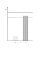
- the symbol (a) indicates “exhaust pipe pressure loss”.
- the symbol (b) indicates “amount of urea water crystallized on the wall surface”.
- the symbol (c) indicates “ammonia production amount”.
- a metal mesh member is formed in a flat plate shape.
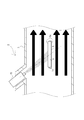
- the dispersion member 50 is disposed so as to be rotatable in the exhaust pipe 3 by a rotation device (not shown). Then, the dispersion member 50 is rotated so as to face the flow direction of the exhaust gas (the right direction in FIG. 4).
- the dispersion member 50 is rotated in a direction parallel to the flow direction of the exhaust gas.
- the dispersion member 50 is rotated so as to face the injection direction of the urea water (in a direction non-parallel to the flow direction of the exhaust gas).
- the urea water injected into the exhaust pipe 3 is everywhere. If there is no collision, the pressure loss of the exhaust gas in the exhaust pipe 3 can be reduced as shown in FIG. However, in such a case, as shown in FIG. 6, the urea water injected into the exhaust pipe 3 is difficult to be mixed and diffused. That is, the urea water easily adheres to the wall surface in the exhaust pipe 3, and the attached urea water is crystallized.
- the symbol (a) indicates “exhaust pipe pressure loss”. Further, the symbol (b) indicates “amount of urea water crystallized on the wall surface”. Further, the symbol (c) indicates “ammonia production amount”.
- the dispersion member 5 in the present embodiment is formed of a porous member made of ceramic or metal. With such a configuration, when urea water collides with the dispersion member 5, the urea water can be instantly evaporated by the heat of the exhaust gas stored in the dispersion member 5.
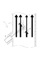
- the dispersion member 5 is formed in a flat plate shape and is installed in the exhaust pipe 3 in a direction parallel to the flow direction of the exhaust gas. More specifically, the exhaust gas generated in the internal combustion engine 1 flows in the exhaust pipe 3 from the left side to the right side in FIG. 2, whereas the dispersion member 5 formed in a flat plate has a pair of front and back sides.
- the plate surfaces 5a are installed so as to be parallel to the left-right direction. That is, in the dispersion member 5, the portion facing the exhaust gas flow direction becomes the side surface 5b having a small area.
- the pair of front and back plate surfaces 5a can be arranged in the exhaust pipe 3 such that the pair of front and back plate surfaces 5a are parallel to the left and right directions and are also arranged to be parallel to the horizontal plane.
- the dispersion member 5 is installed on the wall surface in the exhaust pipe 3 with the pair of front and back plate surfaces 5a oriented in the vertical direction.
- the dispersion member 5 is fixed to the wall surface in the exhaust pipe 3. That is, the dispersion member 5 is not rotated like the conventional dispersion member 50.
- the two end surfaces of the dispersion member 5 on the wall surface side in the exhaust pipe 3 and the wall surface in the exhaust pipe 3 can be provided continuously, and no gap is formed between these members.
- the dispersion member 5 when the dispersion member 5 is rotated, that is, when a gap is formed between the two end surfaces of the dispersion member 5 on the wall surface side in the exhaust pipe 3 and the wall surface in the exhaust pipe 3.
- the urea water injected from the injection nozzle 43 into the exhaust pipe 3 may enter the gap and adhere to the wall surface in the exhaust pipe 3 to be crystallized.
- the two end surfaces of the dispersion member 5 on the wall surface side in the exhaust pipe 3 and the wall surface in the exhaust pipe 3 are provided in series, so that there is a gap between these members. Is not formed. That is, it is possible to prevent the urea water from entering the gap between these members and adhering to the wall surface in the exhaust pipe 3 to be crystallized.
- the fixing method to the wall surface in the exhaust pipe 3 of the dispersion member 5 is not specifically limited. That is, the dispersion member 5 and the exhaust pipe 3 may be provided integrally.
- the dispersion member case 9 may be installed in the exhaust pipe 3 and the dispersion member 5 may be fixed to the dispersion member case 9 so as to be replaceable. According to this configuration, when the dispersion member 5 is contaminated with PM in the exhaust gas, the dispersion member 5 is replaced with a new dispersion member 5 or once removed from the wall surface in the exhaust pipe 3 and washed. It can be attached to the wall surface in the exhaust pipe 3 again.
- the dispersion member 5 since the dispersion member 5 is fixed to the wall surface in the exhaust pipe 3, the dispersion member 50 can be rotated as compared with the exhaust purification system having the dispersion member 50 that is rotatably installed. No moving device is required. Therefore, the exhaust purification system 2 of the internal combustion engine 1 can be constructed with a simple configuration with extremely few parts. In particular, the inside of the exhaust pipe 3 becomes a high temperature due to the exhaust gas when the internal combustion engine 1 is driven, and becomes a low temperature (same as the temperature of the outside air) when the internal combustion engine 1 is not driven. It is. That is, in the exhaust pipe 3, the durability of the exhaust purification system 2 is required. However, as described above, the exhaust purification system 2 does not use the rotating device of the dispersion member 50, and the number of parts is extremely small. Durability can be improved.
- the dispersion member 5 is disposed so that the plane center of the dispersion member 5 is positioned on the extension of the injection center line of the injection nozzle 43.
- the dispersing member 5 can also be arranged so that the plane center thereof is located on the rear side of the extension of the injection center line of the injection nozzle 43. That is, the urea water injected from the injection nozzle 43 is made to flow in the flow direction of the exhaust gas (rightward in FIG. 1) by the flow of the exhaust gas (while maintaining the momentum when injected) and collides with the dispersion member 5
- the dispersion member 5 is disposed at a position where the urea water is flowed. That is, the position of the dispersion member 5 in the exhaust gas flow direction is not particularly limited as long as the dispersion member 5 is disposed at a position where the urea water injected from the injection nozzle 43 collides.
- the exhaust purification system 2 of the internal combustion engine 1 is A reduction catalyst 6 disposed in the exhaust pipe 3 (exhaust passage) of the internal combustion engine 1; A reducing agent injection device 4 for injecting a reducing agent into the exhaust pipe 3 from the upstream side of the reduction catalyst 6;
- a dispersion member 5 (reducing agent evaporation promoting member) is installed at a position upstream of the reducing catalyst 6 in the exhaust pipe 3 and where the reducing agent injected from the reducing agent injection device 4 is sprayed.
- the dispersion member 5 is formed of a porous member, and is fixed in the exhaust pipe 3 in a state parallel to the flow direction of the exhaust gas.
- the exhaust purification system 2 of the internal combustion engine 1 can generate uniform ammonia in the exhaust pipe 3, efficiently reduce and purify nitrogen oxides in the exhaust gas by the reduction catalyst 6, and A decrease in the performance of the internal combustion engine 1 due to an increase in pressure in the exhaust pipe 3 can be prevented.
- the reducing agent is preferably urea water.
- the exhaust gas purification system 2 of the internal combustion engine 1 can handle the reducing agent more easily than, for example, the case of using ammonia that is toxic and difficult to handle. Therefore, the exhaust purification system 2 of the internal combustion engine 1 can be constructed more easily.
- the reducing agent injection device 4 includes an injection nozzle 43,
- the spray nozzle 43 is preferably a single fluid nozzle.
- the exhaust purification system 2 of the internal combustion engine 1 uses only the pressure of the liquid (reducing agent) (without mixing with gas), for example, as compared with the case where a two-fluid nozzle is used. It can be injected into the exhaust pipe 3. Therefore, the exhaust purification system 2 of the internal combustion engine 1 can be constructed with a simpler configuration without increasing the number of parts.
- FIG. 7 it is also possible to adopt a configuration in which dispersive members having different mesh roughness are arranged vertically. More specifically, two upper and lower dispersion members (hereinafter, the upper dispersion member is referred to as “upper dispersion member 51” and the lower dispersion member is referred to as “lower dispersion member 52”) are arranged.
- the upper dispersion member 51 and the lower dispersion member 52 are arranged such that the plane center thereof is an extension of the injection center line of the injection nozzle 43. Further, the upper dispersion member 51 is disposed in the horizontal direction in the vicinity of the upper and lower central portions in the exhaust pipe 3.
- the lower dispersion member 52 is disposed in the horizontal direction obliquely below and downstream of the upper dispersion member 51.
- the upper dispersion member 51 and the lower dispersion member 52 are configured in a mesh shape or a flat plate shape in which a large number of holes are opened with metal or the like.
- the upper dispersion member 51 and the lower dispersion member 52 are formed so that the upper dispersion member 51 is coarse and the lower dispersion member 52 is densely formed.
- the pair of front and back plate surfaces 52 a of the lower dispersion member 52 is preferably configured to be larger than the pair of front and back plate surfaces 51 a of the upper dispersion member 51 in proportion to the spread of urea water injected from the injection nozzle 43. .
- the number of dispersing members is not particularly limited, and may be three or more. That is, in the plurality of dispersion members, the dispersion member closer to the injection nozzle 43 has a coarser mesh, and the center of the plate surface of each dispersion member is positioned on the extension of the injection center line of the injection nozzle 43. What is necessary is just to be arrange
- the urea water colliding with the lower dispersion member 52 adheres or is reflected and subdivided. That is, the urea water easily evaporates, and uniform ammonia is easily generated in the exhaust pipe 3. Therefore, as the number of stages of the dispersing members increases, ammonia is more easily generated in the exhaust pipe 3. Further, since the upper dispersion member 51 and the lower dispersion member 52 are parallel to the flow direction of the exhaust gas, the pressure loss of the exhaust gas is not increased.
- the present invention can be used in the technology of an exhaust purification system for purifying exhaust gas discharged from an internal combustion engine through an exhaust pipe.
Landscapes
- Engineering & Computer Science (AREA)
- Chemical & Material Sciences (AREA)
- Chemical Kinetics & Catalysis (AREA)
- Combustion & Propulsion (AREA)
- Mechanical Engineering (AREA)
- General Engineering & Computer Science (AREA)
- Health & Medical Sciences (AREA)
- Toxicology (AREA)
- Exhaust Gas After Treatment (AREA)
- Exhaust Gas Treatment By Means Of Catalyst (AREA)
Abstract
Description
この方法による排気ガスの浄化効率を高めるためには、排気管内に噴射される尿素水を効率的に蒸発させ、排気管内に均一なアンモニアを生成する必要がある。
例えば、排気管内の排気ガスの温度が低い場合には、排気管内に噴射される尿素水を効率的に蒸発させることができない。したがって、排気管内に均一なアンモニアを生成するための時間がかかるので、排気管の長さを長くする必要がある。
しかしながら、このような構成では、排気管の長さが長くなるため、排気管を設置するために大きなスペースが必要となるという問題点がある。また、排気管内の壁面に尿素水が付着しやすくなり、その付着した尿素水が結晶化するという問題点がある。
この技術によれば、排気管内に噴射される尿素水は、メッシュ部材に衝突して細分化され、該メッシュ部材を通過する排気ガス中に混合されることとなる。また、細分化された尿素水は、該メッシュ部材の下流側に設けられた拡散部材に衝突することによって、排気管内に効率的に混合拡散されることとなる。また、金属製のメッシュ部材は排気ガスの熱により高温となるため、メッシュ部材に衝突した尿素水の蒸発が促進されることとなる。
したがって、この技術によれば、排気管内に均一なアンモニアを生成することができる。つまり、排気管の長さを長くする必要がなく、排気管を設置するための大きなスペースも必要ない。また、排気管内の壁面に尿素水が付着して結晶化することを防止することができる。
しかしながら、特許文献1に記載の技術では、排気管内の排気ガスは、排気ガスの流れ方向に対して対向するように配置されたメッシュ部材と拡散部材とを通過するものである。したがって、該メッシュ部材と該拡散部材とを通過する際に排気ガスの圧力損失が生じる。その結果、該メッシュ部材および該拡散部材よりも上流側の排気管内の圧力が上昇し、内燃機関の性能が低下するという問題点があった。
この技術によれば、尿素水の非噴射時には、メッシュ部材が排気ガスの流れ方向に対して平行となる向きに回動される。したがって、排気ガスが該メッシュ部材を通過する際に圧力損失が生じず、該メッシュ部材よりも上流側の排気管内の圧力が上昇することを防止し、内燃機関の性能の低下を防止することができる。
2 排気浄化システム(SCR)
3 排気管
4 還元剤噴射装置
5 分散部材
5a 板面
還元剤とは、排気ガス中に供給されて還元触媒6により排気ガス成分を還元浄化するものである。なお、本実施形態において、還元剤として尿素水を用いるものとして、以下の説明を行なう。
なお、還元剤噴射装置4は、本発明に係る「還元剤噴射装置」の一実施形態である。
噴射ノズル43から分散部材5に向けて尿素水をシャワー状または霧状に噴射させることにより、分散部材5に衝突する前の尿素水の細かな粒は、容易に蒸発する。また、尿素水は、分散部材5に衝突して跳ね返る時に細分化されて排気管3内に拡散され、容易に蒸発する。また、分散部材5は、排気ガスの熱により高温となるため、該分散部材5に衝突した尿素水の蒸発を促進することができる(図3参照)。
したがって、排気管3内に均一なアンモニアが発生されるとともに、排気管3内の壁面に尿素水が付着して結晶化することを防止することができる。なお、前記「噴射された尿素水が衝突する位置」とは、噴射された尿素水が排気ガスの流れに乗った後に衝突する位置ではなく、噴射されたときの勢いで衝突する位置を指す。
なお、分散部材5は、本発明に係る「還元剤蒸発促進用部材」の一実施形態である。
なお、還元触媒6は、本発明に係る「還元触媒」の一実施形態である。
また、前述したように、内燃機関1の排気浄化システム2に前記DPFを設けた場合には、該DPFによりPMが捕集された後の排気ガスに対して、尿素水が噴射されて、排気ガス中の窒素酸化物を還元浄化することとなる。
なお、図5および図6のグラフにおいて、符号(a)は、「排気管圧力損失」を示す。また、符号(b)は、「壁面で結晶化した尿素水量」を示す。また、符号(c)は、「アンモニア生成量」を示す。
このように構成されるので、分散部材50が通気性の良いメッシュ部材により形成されていても、図5に示すように、噴射ノズル43から尿素水が噴射される時には、排気ガスが該分散部材50を通過する際に圧力損失が生じる(図4黒塗矢印参照)。その結果、排気管3内にて分散部材50よりも上流側の圧力が上昇し、内燃機関の性能が低下することとなる。
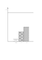
なお、図3のグラフにおいて、符号(a)は、「排気管圧力損失」を示す。また、符号(b)は、「壁面で結晶化した尿素水量」を示す。また、符号(c)は、「アンモニア生成量」を示す。
このような構成により、尿素水が分散部材5に衝突した場合には、その尿素水を分散部材5に蓄えられた排気ガスの熱により瞬時に蒸発させることができる。
このような構成により、図3に示すように、排気ガスが分散部材5を左側から右側へ通過する際に生じる圧力損失を前記従来の分散部材50と比べて大幅に減少させることができる。
内燃機関1の排気管3(排気通路)内に配置された還元触媒6と、
前記還元触媒6より上流側から排気管3内に還元剤を噴射するための還元剤噴射装置4と、
を備えた内燃機関1の排気浄化システム2において、
排気管3内における還元触媒6より上流側であって、かつ還元剤噴射装置4から噴射された前記還元剤が吹き付けられる位置に分散部材5(還元剤蒸発促進用部材)が設置され、
分散部材5は、多孔質部材により形成され、排気ガスの流れ方向に対して平行となる状態で排気管3内に固定されるものである。
前記還元剤は、尿素水であることが望ましい。
還元剤噴射装置4は、噴射ノズル43を備え、
噴射ノズル43は、一流体ノズルであることが望ましい。
より詳細には、上下二枚の分散部材(以下、上側の分散部材を「上分散部材51」、下側の分散部材を「下分散部材52」と称する。)を配置する。上分散部材51および下分散部材52は、その平面中心が噴射ノズル43の噴射中心線の延長上に配置される。また、上分散部材51は、排気管3内の上下中央部付近に水平方向に配置される。また、下分散部材52は、上分散部材51の下流側斜め下方に水平方向に配置される。上分散部材51および下分散部材52は、金属などでメッシュ状または多数の孔を開口した平板状に構成される。上分散部材51および下分散部材52の網の目の粗さは、上分散部材51が粗く、下分散部材52が密に構成される。なお、下分散部材52の表裏一対の板面52aは、噴射ノズル43から噴射された尿素水の広がりに比例して、上分散部材51の表裏一対の板面51aよりも大きく構成することが望ましい。
なお、分散部材の数は、特に限定するものではなく、三枚以上であってもよい。つまり、複数の分散部材は、噴射ノズル43に近い分散部材ほど網の目の粗さが粗く、且つ、噴射ノズル43の噴射中心線の延長上に各分散部材の板面の中心が位置するように平行に配置されるものであればよい。
また、上分散部材51を通り抜けた残りの尿素水は、下分散部材52に衝突する。この下分散部材52の網の目の粗さは密に構成されるため、下分散部材52を通り抜ける尿素水は極僅かとなり、さらに通り抜けた尿素水は細分化されているため容易に蒸発する。また、下分散部材52に衝突した尿素水は付着したり、反射して細分化されたりする。すなわち、尿素水は蒸発し易い状態となり、排気管3内に均一なアンモニアが生成され易くなる。したがって、分散部材の段数を多くするほど、排気管3内にアンモニアが均一に生成され易くなる。また、上分散部材51および下分散部材52は排気ガスの流れ方向と平行であるため、排気ガスの圧力損失を増大させることがない。
Claims (3)
- 内燃機関の排気通路内に配置された還元触媒と、
前記還元触媒より上流側から前記排気通路内に還元剤を噴射するための還元剤噴射装置と、
を備えた内燃機関の排気浄化システムにおいて、
前記排気通路内における前記還元触媒より上流側であって、かつ前記還元剤噴射装置から噴射された前記還元剤が吹き付けられる位置に還元剤蒸発促進用部材が設置され、
前記還元剤蒸発促進用部材は、多孔質部材により形成され、排気ガスの流れ方向に対して平行となる状態で前記排気通路内に固定される、
ことを特徴とする内燃機関の排気浄化システム。 - 前記還元剤は、尿素水である、
ことを特徴とする請求項1に記載の内燃機関の排気浄化システム。 - 前記還元剤噴射装置は、噴射ノズルを備え、
前記噴射ノズルは、一流体ノズルである、
ことを特徴とする請求項1または請求項2に記載の内燃機関の排気浄化システム。
Priority Applications (4)
| Application Number | Priority Date | Filing Date | Title |
|---|---|---|---|
| CN2011800213750A CN102869864A (zh) | 2010-04-30 | 2011-04-28 | 内燃机的排气净化系统 |
| EP11775101.6A EP2565409A4 (en) | 2010-04-30 | 2011-04-28 | EXHAUST GAS CLEANING SYSTEM FOR A COMBUSTION ENGINE |
| US13/643,861 US9086005B2 (en) | 2010-04-30 | 2011-04-28 | Exhaust purification system for internal combustion engine |
| KR1020127029810A KR20130008613A (ko) | 2010-04-30 | 2011-04-28 | 내연 기관의 배기 정화 시스템 |
Applications Claiming Priority (2)
| Application Number | Priority Date | Filing Date | Title |
|---|---|---|---|
| JP2010105974A JP5534925B2 (ja) | 2010-04-30 | 2010-04-30 | 内燃機関の排気浄化システム |
| JP2010-105974 | 2010-04-30 |
Publications (1)
| Publication Number | Publication Date |
|---|---|
| WO2011136320A1 true WO2011136320A1 (ja) | 2011-11-03 |
Family
ID=44861616
Family Applications (1)
| Application Number | Title | Priority Date | Filing Date |
|---|---|---|---|
| PCT/JP2011/060358 Ceased WO2011136320A1 (ja) | 2010-04-30 | 2011-04-28 | 内燃機関の排気浄化システム |
Country Status (6)
| Country | Link |
|---|---|
| US (1) | US9086005B2 (ja) |
| EP (1) | EP2565409A4 (ja) |
| JP (1) | JP5534925B2 (ja) |
| KR (1) | KR20130008613A (ja) |
| CN (1) | CN102869864A (ja) |
| WO (1) | WO2011136320A1 (ja) |
Families Citing this family (12)
| Publication number | Priority date | Publication date | Assignee | Title |
|---|---|---|---|---|
| DE102012000597A1 (de) * | 2012-01-14 | 2013-07-18 | Daimler Ag | Abgassystem einer Brennkraftmaschine und Verfahren zur Aufbereitung eines in Brennkraftmaschinenabgas eingebrachten Reduktionsmittels |
| SE540984C2 (sv) * | 2013-04-12 | 2019-02-19 | Scania Cv Ab | Förfarande och anordning för insprutning av ett reduktionsmedel vid en förbränningsmotor |
| JP2015028312A (ja) * | 2013-07-30 | 2015-02-12 | トヨタ自動車株式会社 | 内燃機関の排気浄化装置 |
| JP5987927B2 (ja) * | 2015-01-27 | 2016-09-07 | 井関農機株式会社 | 作業車両 |
| JP6622496B2 (ja) * | 2015-07-14 | 2019-12-18 | イビデン株式会社 | 拡散部材、排ガス浄化装置及び排ガス浄化装置における拡散部材の使用 |
| JP2017172332A (ja) * | 2016-03-18 | 2017-09-28 | いすゞ自動車株式会社 | エンジン |
| EP3222834B1 (en) * | 2016-03-23 | 2019-05-08 | Volvo Car Corporation | Exhaust gas aftertreatment device for an internal combustion engine |
| EP3339589B1 (en) * | 2016-12-21 | 2020-10-07 | Perkins Engines Company Limited | Method and apparatus for a scr |
| DE102017207449A1 (de) * | 2017-05-03 | 2018-11-08 | Continental Automotive Gmbh | Abgassystem mit Verdampfungselement |
| DE102017124276B4 (de) * | 2017-10-18 | 2025-08-14 | Purem GmbH | Mischanordnung |
| JP2019127880A (ja) * | 2018-01-24 | 2019-08-01 | フタバ産業株式会社 | 撹拌装置 |
| DE102024124023B3 (de) | 2024-08-22 | 2025-08-21 | Denk Keramische Werkstätten e.K. | Anordnung zur Einmischung eines Reduktionsmittels in einen Abgasstrom, Verbrennungsanlage mit einer solchen Anordnung sowie Verwendung einer keramischen Prallplatte zur Einmischung eines Reduktionsmittels |
Citations (3)
| Publication number | Priority date | Publication date | Assignee | Title |
|---|---|---|---|---|
| JPH08177467A (ja) * | 1994-10-12 | 1996-07-09 | Robert Bosch Gmbh | 自己着火式の内燃機関の排ガスを後処理するための装置 |
| JP2009041371A (ja) | 2007-08-06 | 2009-02-26 | Bosch Corp | 内燃機関の排気浄化装置及びミキサーユニット |
| JP2010038020A (ja) | 2008-08-04 | 2010-02-18 | Toyota Motor Corp | 内燃機関の排気浄化装置 |
Family Cites Families (3)
| Publication number | Priority date | Publication date | Assignee | Title |
|---|---|---|---|---|
| DE19806265C5 (de) * | 1998-02-16 | 2004-07-22 | Siemens Ag | Dosiersystem |
| US6449947B1 (en) * | 2001-10-17 | 2002-09-17 | Fleetguard, Inc. | Low pressure injection and turbulent mixing in selective catalytic reduction system |
| JP2007032472A (ja) | 2005-07-28 | 2007-02-08 | Hitachi Ltd | 尿素水を用いた排気処理装置 |
-
2010
- 2010-04-30 JP JP2010105974A patent/JP5534925B2/ja not_active Expired - Fee Related
-
2011
- 2011-04-28 WO PCT/JP2011/060358 patent/WO2011136320A1/ja not_active Ceased
- 2011-04-28 EP EP11775101.6A patent/EP2565409A4/en not_active Withdrawn
- 2011-04-28 US US13/643,861 patent/US9086005B2/en not_active Expired - Fee Related
- 2011-04-28 KR KR1020127029810A patent/KR20130008613A/ko not_active Abandoned
- 2011-04-28 CN CN2011800213750A patent/CN102869864A/zh active Pending
Patent Citations (3)
| Publication number | Priority date | Publication date | Assignee | Title |
|---|---|---|---|---|
| JPH08177467A (ja) * | 1994-10-12 | 1996-07-09 | Robert Bosch Gmbh | 自己着火式の内燃機関の排ガスを後処理するための装置 |
| JP2009041371A (ja) | 2007-08-06 | 2009-02-26 | Bosch Corp | 内燃機関の排気浄化装置及びミキサーユニット |
| JP2010038020A (ja) | 2008-08-04 | 2010-02-18 | Toyota Motor Corp | 内燃機関の排気浄化装置 |
Non-Patent Citations (1)
| Title |
|---|
| See also references of EP2565409A4 * |
Also Published As
| Publication number | Publication date |
|---|---|
| JP2011236746A (ja) | 2011-11-24 |
| US9086005B2 (en) | 2015-07-21 |
| EP2565409A4 (en) | 2013-12-18 |
| EP2565409A1 (en) | 2013-03-06 |
| US20130052095A1 (en) | 2013-02-28 |
| CN102869864A (zh) | 2013-01-09 |
| JP5534925B2 (ja) | 2014-07-02 |
| KR20130008613A (ko) | 2013-01-22 |
Similar Documents
| Publication | Publication Date | Title |
|---|---|---|
| JP5534925B2 (ja) | 内燃機関の排気浄化システム | |
| US9821282B2 (en) | Diesel exhaust fluid mixing system for a linear arrangement of diesel oxidation catalyst and selective catalytic reduction filter | |
| JP5714844B2 (ja) | 排気ガス浄化装置 | |
| US9719386B2 (en) | Multi-lobed soot blower | |
| US20120151902A1 (en) | Biased reductant mixer | |
| US20110079003A1 (en) | Reductant nozzle indentation mount | |
| JP6167031B2 (ja) | 排気ガス浄化装置 | |
| US20130219871A1 (en) | Mounting Assembly for a Reductant Injector | |
| WO2011126930A2 (en) | Ring reductant mixer | |
| US10450921B2 (en) | Exhaust purification system | |
| JP2011052611A (ja) | 排気ガス浄化装置 | |
| JP5664771B2 (ja) | 内燃機関の排気浄化装置 | |
| JP2020023953A (ja) | 排気浄化装置 | |
| JP2008240722A (ja) | 排気ガス浄化装置 | |
| JP4961847B2 (ja) | 排気ガス浄化方法及び排気ガス浄化システム | |
| JP4830570B2 (ja) | 排気ガス浄化システム | |
| JP2018105248A (ja) | 排気ガス浄化装置 | |
| WO2013090484A1 (en) | Fluid injection lance with balanced flow distribution | |
| CN105765189B (zh) | 喷射模块和具有喷射模块的排气系统 | |
| JP2021071054A (ja) | 尿素水分散装置及び尿素水分散装置の取付構造 | |
| CN106536882A (zh) | 喷射模块和具有喷射模块的废气系统 | |
| JP2015206333A (ja) | 排気ガス浄化装置 | |
| WO2011067966A1 (ja) | エンジンの排気浄化装置 | |
| CN112096489A (zh) | 用于废气后处理的废气系统 | |
| JP2012002084A (ja) | 排気流案内用ガイド及び排気流案内用ガイドを備える排気浄化装置 |
Legal Events
| Date | Code | Title | Description |
|---|---|---|---|
| WWE | Wipo information: entry into national phase |
Ref document number: 201180021375.0 Country of ref document: CN |
|
| 121 | Ep: the epo has been informed by wipo that ep was designated in this application |
Ref document number: 11775101 Country of ref document: EP Kind code of ref document: A1 |
|
| WWE | Wipo information: entry into national phase |
Ref document number: 13643861 Country of ref document: US |
|
| NENP | Non-entry into the national phase |
Ref country code: DE |
|
| WWE | Wipo information: entry into national phase |
Ref document number: 2011775101 Country of ref document: EP |
|
| ENP | Entry into the national phase |
Ref document number: 20127029810 Country of ref document: KR Kind code of ref document: A |