WO2011136344A1 - 化学センサ - Google Patents
化学センサ Download PDFInfo
- Publication number
- WO2011136344A1 WO2011136344A1 PCT/JP2011/060404 JP2011060404W WO2011136344A1 WO 2011136344 A1 WO2011136344 A1 WO 2011136344A1 JP 2011060404 W JP2011060404 W JP 2011060404W WO 2011136344 A1 WO2011136344 A1 WO 2011136344A1
- Authority
- WO
- WIPO (PCT)
- Prior art keywords
- unit
- sample
- substance
- measured
- reaction
- Prior art date
- Legal status (The legal status is an assumption and is not a legal conclusion. Google has not performed a legal analysis and makes no representation as to the accuracy of the status listed.)
- Ceased
Links
Images

Classifications
-
- B—PERFORMING OPERATIONS; TRANSPORTING
- B01—PHYSICAL OR CHEMICAL PROCESSES OR APPARATUS IN GENERAL
- B01L—CHEMICAL OR PHYSICAL LABORATORY APPARATUS FOR GENERAL USE
- B01L3/00—Containers or dishes for laboratory use, e.g. laboratory glassware; Droppers
- B01L3/50—Containers for the purpose of retaining a material to be analysed, e.g. test tubes
- B01L3/502—Containers for the purpose of retaining a material to be analysed, e.g. test tubes with fluid transport, e.g. in multi-compartment structures
- B01L3/5027—Containers for the purpose of retaining a material to be analysed, e.g. test tubes with fluid transport, e.g. in multi-compartment structures by integrated microfluidic structures, i.e. dimensions of channels and chambers are such that surface tension forces are important, e.g. lab-on-a-chip
-
- G—PHYSICS
- G01—MEASURING; TESTING
- G01N—INVESTIGATING OR ANALYSING MATERIALS BY DETERMINING THEIR CHEMICAL OR PHYSICAL PROPERTIES
- G01N1/00—Sampling; Preparing specimens for investigation
- G01N1/02—Devices for withdrawing samples
- G01N1/22—Devices for withdrawing samples in the gaseous state
-
- G—PHYSICS
- G01—MEASURING; TESTING
- G01N—INVESTIGATING OR ANALYSING MATERIALS BY DETERMINING THEIR CHEMICAL OR PHYSICAL PROPERTIES
- G01N1/00—Sampling; Preparing specimens for investigation
- G01N1/02—Devices for withdrawing samples
- G01N1/22—Devices for withdrawing samples in the gaseous state
- G01N1/2202—Devices for withdrawing samples in the gaseous state involving separation of sample components during sampling
- G01N1/2214—Devices for withdrawing samples in the gaseous state involving separation of sample components during sampling by sorption
-
- G—PHYSICS
- G01—MEASURING; TESTING
- G01N—INVESTIGATING OR ANALYSING MATERIALS BY DETERMINING THEIR CHEMICAL OR PHYSICAL PROPERTIES
- G01N1/00—Sampling; Preparing specimens for investigation
- G01N1/28—Preparing specimens for investigation including physical details of (bio-)chemical methods covered elsewhere, e.g. G01N33/50, C12Q
-
- G—PHYSICS
- G01—MEASURING; TESTING
- G01N—INVESTIGATING OR ANALYSING MATERIALS BY DETERMINING THEIR CHEMICAL OR PHYSICAL PROPERTIES
- G01N27/00—Investigating or analysing materials by the use of electric, electrochemical, or magnetic means
- G01N27/26—Investigating or analysing materials by the use of electric, electrochemical, or magnetic means by investigating electrochemical variables; by using electrolysis or electrophoresis
- G01N27/28—Electrolytic cell components
-
- G—PHYSICS
- G01—MEASURING; TESTING
- G01N—INVESTIGATING OR ANALYSING MATERIALS BY DETERMINING THEIR CHEMICAL OR PHYSICAL PROPERTIES
- G01N33/00—Investigating or analysing materials by specific methods not covered by groups G01N1/00 - G01N31/00
- G01N33/0004—Gaseous mixtures, e.g. polluted air
- G01N33/0009—General constructional details of gas analysers, e.g. portable test equipment
- G01N33/0027—General constructional details of gas analysers, e.g. portable test equipment concerning the detector
- G01N33/0036—General constructional details of gas analysers, e.g. portable test equipment concerning the detector specially adapted to detect a particular component
- G01N33/0059—Avoiding interference of a gas with the gas to be measured
- G01N33/006—Avoiding interference of water vapour with the gas to be measured
-
- B—PERFORMING OPERATIONS; TRANSPORTING
- B01—PHYSICAL OR CHEMICAL PROCESSES OR APPARATUS IN GENERAL
- B01L—CHEMICAL OR PHYSICAL LABORATORY APPARATUS FOR GENERAL USE
- B01L2300/00—Additional constructional details
- B01L2300/06—Auxiliary integrated devices, integrated components
- B01L2300/0627—Sensor or part of a sensor is integrated
- B01L2300/0645—Electrodes
-
- B—PERFORMING OPERATIONS; TRANSPORTING
- B01—PHYSICAL OR CHEMICAL PROCESSES OR APPARATUS IN GENERAL
- B01L—CHEMICAL OR PHYSICAL LABORATORY APPARATUS FOR GENERAL USE
- B01L2300/00—Additional constructional details
- B01L2300/08—Geometry, shape and general structure
- B01L2300/0809—Geometry, shape and general structure rectangular shaped
- B01L2300/0825—Test strips
-
- B—PERFORMING OPERATIONS; TRANSPORTING
- B01—PHYSICAL OR CHEMICAL PROCESSES OR APPARATUS IN GENERAL
- B01L—CHEMICAL OR PHYSICAL LABORATORY APPARATUS FOR GENERAL USE
- B01L2300/00—Additional constructional details
- B01L2300/18—Means for temperature control
- B01L2300/1805—Conductive heating, heat from thermostatted solids is conducted to receptacles, e.g. heating plates, blocks
- B01L2300/1822—Conductive heating, heat from thermostatted solids is conducted to receptacles, e.g. heating plates, blocks using Peltier elements
-
- B—PERFORMING OPERATIONS; TRANSPORTING
- B01—PHYSICAL OR CHEMICAL PROCESSES OR APPARATUS IN GENERAL
- B01L—CHEMICAL OR PHYSICAL LABORATORY APPARATUS FOR GENERAL USE
- B01L2400/00—Moving or stopping fluids
- B01L2400/04—Moving fluids with specific forces or mechanical means
- B01L2400/0403—Moving fluids with specific forces or mechanical means specific forces
- B01L2400/0406—Moving fluids with specific forces or mechanical means specific forces capillary forces
-
- G—PHYSICS
- G01—MEASURING; TESTING
- G01N—INVESTIGATING OR ANALYSING MATERIALS BY DETERMINING THEIR CHEMICAL OR PHYSICAL PROPERTIES
- G01N1/00—Sampling; Preparing specimens for investigation
- G01N1/02—Devices for withdrawing samples
- G01N1/22—Devices for withdrawing samples in the gaseous state
- G01N1/2202—Devices for withdrawing samples in the gaseous state involving separation of sample components during sampling
- G01N1/2214—Devices for withdrawing samples in the gaseous state involving separation of sample components during sampling by sorption
- G01N2001/2217—Devices for withdrawing samples in the gaseous state involving separation of sample components during sampling by sorption using a liquid
-
- G—PHYSICS
- G01—MEASURING; TESTING
- G01N—INVESTIGATING OR ANALYSING MATERIALS BY DETERMINING THEIR CHEMICAL OR PHYSICAL PROPERTIES
- G01N1/00—Sampling; Preparing specimens for investigation
- G01N1/02—Devices for withdrawing samples
- G01N1/22—Devices for withdrawing samples in the gaseous state
- G01N2001/2282—Devices for withdrawing samples in the gaseous state with cooling means
Definitions
- the present invention relates to a chemical sensor for detecting a gas component in a gas or a substance to be measured such as a virus or an allergen.
- an electrochemical biosensor test piece uses a body fluid such as blood, a fermented product, or a natural product as a sample, and detects charges generated by enzymatic reaction of this sample with a reagent (see Patent Document 1). .
- This electrochemical biosensor test piece has a capillary space for introducing a sample by utilizing capillary action, so that even a small amount of sample accurately measures an enzyme reaction with a reagent and a charge. Yes.
- the sample needs to be liquid due to reaction restrictions. Therefore, it is impossible to detect a substance to be measured such as a gas component in a gas, a virus, or an allergen.
- a pretreatment for dissolving the substance to be measured in a liquid is required.
- This pre-processing is a complicated process such as using a large apparatus or manually.
- the present invention has been made in view of the above problems, and an object thereof is to provide a chemical sensor capable of dissolving a substance to be measured in a gas in a liquid by a simple method.
- the chemical sensor includes a sensor holding unit, a gas injection hole into which a gas containing a substance to be measured is injected, and a sample collecting part for collecting the substance to be measured contained in the gas injected from the gas injection hole
- a sample transporting part for transporting the substance to be measured collected by the sample collecting part to the sample reaction part, a sample reaction part having a reactive substance that causes a predetermined reaction with the substance to be measured transported by the sample transporting part, and a sample A detector that detects a substance to be measured that has reacted with the reactant in the reaction unit.
- the sample collection unit has a Peltier element that liquefies water vapor contained in the gas injected from the gas injection hole.
- a solution containing a substance to be measured can be created by liquefying water vapor contained in the gas injected from the gas injection hole by the Peltier cooling effect of the Peltier element. Therefore, the sample collection unit can collect a solution containing the substance to be measured from the gas injected from the gas injection hole.
- the gas injection hole, the sample collection unit, the sample transport unit, the sample reaction unit, and the detection unit are integrally formed with the sensor holding unit.
- the sample transporting section has a capillary structure, and one end of the capillary structure may be close to the Peltier element.
- the solution liquefied by the Peltier device by the capillary phenomenon of the capillary structure can be transported to the sample reaction part without using a special structure.
- the sample reaction unit may have at least one of an antibody, an enzyme, a receptor, and a protein that specifically react with the substance to be measured conveyed by the sample conveyance unit.
- the substance to be measured can be specifically detected by the antigen-antibody reaction with the substance to be measured.
- the sample reaction unit may include a heating unit that heats the substance to be measured conveyed by the sample conveyance unit, and a temperature measurement unit that measures the temperature of the substance to be measured.
- a heating unit that heats the substance to be measured conveyed by the sample conveyance unit
- a temperature measurement unit that measures the temperature of the substance to be measured.
- the detection unit may include an antibody that binds to the substance to be measured that has reacted with the reactant and an electrode that carries the antibody, and the electrode may have a porous structure. Thereby, since the immobilization area of the antibody can be increased, the detection sensitivity can be increased.
- the chemical sensor is composed of a plurality of unit sensors integrally formed on one sensor holding unit, and each unit sensor is composed of a gas injection hole, a sample collection unit, a sample transport unit, a sample reaction unit, and a detection unit. It may be. By disposing a plurality of unit sensors integrally in one sensor holding part, it is possible to suppress the disposable use of the sensor.
- the substance to be measured in the gas can be dissolved in the liquid by a simple method due to the Peltier cooling effect of the Peltier element.
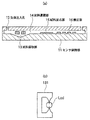
- FIG. 1A is a cross-sectional view showing the overall configuration of the chemical sensor according to the first embodiment of the present invention.
- FIG. 1B is a Peltier provided in the sample collection unit 13 of FIG. It is a schematic diagram which shows an element.
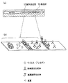
- FIG. 2A and FIG. 2B are schematic diagrams illustrating specific configuration examples of the sample reaction unit 15 and the detection unit 16 in FIG.
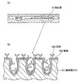
- FIGS. 3A and 3B are schematic views showing a specific configuration example of the detection unit 16 in FIG.
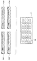
- FIGS. 4A and 4B are schematic views showing a specific configuration example of the sample reaction unit 15 according to the second embodiment of the present invention.
- It is a conceptual diagram which shows the whole structure of the chemical sensor concerning the 3rd Embodiment of this invention.
- the chemical sensor according to the first embodiment includes a sensor holder 11 having a function as a substrate that supports the entire chemical sensor, a gas injection hole 12 into which a gas such as air containing a substance to be measured is injected, and a gas A sample collection unit 13 that collects a substance to be measured contained in the gas injected from the injection hole 12, a sample conveyance unit 14 that conveys the measurement substance collected by the sample collection unit 13 to the sample reaction unit 15, and a sample conveyance A sample reaction unit 15 having a reaction substance that causes a predetermined reaction with the measurement target substance conveyed by the unit 14 and a detection unit 16 that detects the measurement target substance that has reacted with the reaction substance in the sample reaction unit 15 are provided.
- the sensor holding unit 11 is a substantially flat substrate, and is made of, for example, a semiconductor (Si, SiC, etc.) substrate or a glass substrate that can be easily processed finely.
- the sensor holding part 11 and a protective member to be described later can be manufactured by micromachining.
- On one main surface of the sensor holding unit 11, a sample collection unit 13, a sample transport unit 14, a sample reaction unit 15, and a detection unit 16 are arranged in order.
- a protective member is arranged above the main surface of the sensor holding unit 11 so as to cover the sample collection unit 13, the sample transport unit 14, the sample reaction unit 15 and the detection unit 16, and holes are formed in at least two places of the protection member. Is open. The at least two holes are for introducing and discharging the gas containing the substance to be measured.
- the protective member and the sensor holding unit 11 are arranged so that the gas can be effectively introduced and discharged through the two holes. It is preferable to join by a joining method capable of maintaining airtightness.
- One of the at least two locations is provided, for example, in front of the sample collection unit 13, and gas is introduced into the protective member from at least one of the holes and led out from the other hole.
- One hole on the side where the gas is introduced is referred to as a gas injection hole 12.
- the sample collection unit 13 collects the substance to be measured contained in the gas in the detection space formed by covering the sensor holding unit 11 with the protective member provided with the gas injection hole 12.
- the sample transport unit 14, the sample reaction unit 15, and the detection unit 16 are integrally formed.
- the sample collection unit 13 is disposed in the vicinity of the gas injection hole 12 and makes it easy to collect a substance to be measured contained in the gas injected from the gas injection hole 12.
- examples of the “substance to be measured contained in the gas” include gas components in the gas, viruses, and allergens.
- FIG. 1A shows an example in which the gas injection hole 12 is provided in front of the sample collection unit 13, but as described above, in the present invention, the sample collection unit 13 is formed in the gas injection hole 12.
- the gas injection hole 12 may be provided on the sample collection unit 13 as long as they are arranged close to each other.
- the sample collection part 13 has the Peltier device 131 which liquefies the water vapor
- One current of the Peltier element 131 absorbs heat from the surrounding gas by causing a current to flow through the joint between the two kinds of metals constituting the Peltier element 131.
- FIG. 1B is a plan view of the sample collection unit 13 shown in FIG. 1A as viewed from above, and the lower side of FIG. 1B is the gas injection hole 12 side in FIG. 1A. Yes, the upper side of FIG. 1 (b) is the sample carrying part 14 side in FIG. 1 (a).
- FIG. 1B is a plan view of the sample collection unit 13 shown in FIG. 1A as viewed from above, and the lower side of FIG. 1B is the gas injection hole 12 side in FIG. 1A. Yes, the upper side of FIG. 1 (b) is the sample carrying part 14 side in FIG. 1 (a).
- FIG. 1B is lique
- the Peltier element 131 constituting the sample collection unit 13 is supported by the sensor holding unit 11 at both ends so as not to disturb the cooling function, for example, and, for example, two kinds of metal via wiring formed in the support structure Current is injected into the junction.
- the Peltier material for example, copper oxide or a polysilicon thin film is preferable from the viewpoint of miniaturization.
- poured from the gas injection hole can be liquefied by the Peltier cooling effect by a Peltier device. Since the substance to be measured is dissolved in the liquefied water vapor, the solution Lqd containing the substance to be measured can be prepared. Therefore, the sample collection unit 13 can automatically collect the solution Lqd containing the substance to be measured from the gas injected from the gas injection hole 12.
- the sample transport unit 14 has a capillary structure with a width and a depth of about 100 ⁇ m, and one end of the capillary structure is close to the Peltier element of the sample collection unit 13.
- the solution Lqd containing the substance to be measured collected by the Peltier device can be introduced into the capillary structure.
- the solution Lqd introduced into the capillary structure is transported to the sample reaction unit 15 by capillary action.
- the sample transport unit 14 can transport the solution liquefied by the Peltier element by the capillary phenomenon of the capillary structure to the sample reaction unit 15 without using a special structure.
- a capillary structure with a width t of about 100 ⁇ m can be manufactured by micromachining.
- the capillary surface is preferably subjected to a hydrophilic treatment so that the solution Lqd can easily move.
- a method of forming a silicon oxide film on the surface or a method of covering the surface with a water-soluble polymer such as polyethylene glycol is easy to produce.
- the sample reaction unit 15 has at least one of an antibody, an enzyme, a receptor, and a protein as a reaction substance that specifically reacts with the substance to be measured conveyed by the sample conveyance unit 14.
- an enzyme-immobilized antibody as an example of an antibody that specifically reacts with a substance to be measured such as a virus or an allergen will be described.
- the enzyme-immobilized antibody and the virus or allergen specifically bind to form a complex. This complex is transported to the detection unit 16.
- the enzyme-immobilized antibody include anti-HA antibody and ALP enzyme.
- the detection unit 16 has an electrode made of a metal thin film such as gold or platinum, and the capture site carries a substrate-immobilized antibody as an example of an antibody that binds to the above complex.
- the substrate-immobilized antibody include an anti-HA antibody, and examples of the substrate include paraaminophenyl phosphate (pAPP), which is a substrate that specifically reacts with an ALP enzyme.
- pAPP paraaminophenyl phosphate
- the substrate-immobilized antibody can capture viruses and allergens bound to the enzyme-immobilized antibody. Thereby, the substrate of the substrate-immobilized antibody and the enzyme of the enzyme-immobilized antibody are brought close to each other at the capture site, and an enzyme-substrate reaction occurs here.
- the reaction produces paraaminophenol (pAP).
- the generated pAP can be oxidized to paraquinoneimine (pQI) on the electrode.
- the detection unit 16 can detect the substance to be measured. Since this redox reaction between pAP and pQI is reversible, the electrode is formed in a comb-like shape facing each other, and on the other hand, pAP is oxidized, and on the other hand, pQI is reduced to form a redox cycle. And the current value obtained can be amplified. Thereby, highly sensitive detection becomes possible.
- the detection unit 16 includes an antibody (substrate-immobilized antibody) 163 that binds to a substance to be measured (virus or allergen) that has reacted with a reactive substance (enzyme-immobilized antibody), an electrode 162 that supports the antibody 163, and anodized silicon 161.
- an antibody substrate-immobilized antibody
- a reactive substance enzyme-immobilized antibody
- an electrode 162 that supports the antibody 163, and anodized silicon 161.
- a plurality of concave portions are formed on the main surface of the anodized silicon 161.
- the electrode 162 is made of a thin film of gold (Au) that is contacted with a uniform thickness along the concavo-convex shape of the main surface of the anodized silicon 161.
- Au gold
- the electrode 162 has a porous structure.
- the antibody 163 is supported on the surface of the electrode 162. Since the antibody 163 is also carried in the recess, the detection unit 16 can carry a large number of antibodies 163. Since the electrode 162 has a porous structure, the immobilization area of the antibody 163 can be increased, so that the detection sensitivity can be increased.
- a method for immobilizing the antibody 163 for example, a method such as a self-assembled monolayer (SAM) that binds to the gold surface via a thiol group may be used.
- SAM self-assembled monolayer
- a solution containing a substance to be measured (virus or allergen) is created by liquefying water vapor contained in the gas injected from the gas injection hole 12 by the Peltier cooling effect of the Peltier element. Can do. Therefore, the sample collection unit 13 can collect the substance to be measured from the gas injected from the gas injection hole 12.
- the chemical sensor according to the present invention includes the sample collection unit 13, the sample transport unit 14, the sample reaction unit 15, and the detection in a narrow detection space formed by covering the sensor holding unit 11 with a protective member. Since the unit 16 is integrated and integrally formed, it can be reduced in size and weight, and a small amount of sample can be detected with a small amount of a reactive substance such as an antibody or an enzyme, thereby reducing the amount of expensive reactive substance used. Can be detected at low cost.
- a reactive substance such as an antibody or an enzyme
- the sample transport unit 14 has a capillary structure, and one end of the capillary structure is close to the Peltier element. Thereby, the solution liquefied by the Peltier device by the capillary phenomenon of the capillary structure can be transported to the sample reaction unit 15 without using a special structure.
- the sample reaction unit 15 has an antibody (an enzyme-immobilized antibody) that specifically reacts with the substance to be measured conveyed by the sample conveyance unit 14.
- the substance to be measured can be specifically detected by the antigen-antibody reaction between the enzyme-immobilized antibody and the substance to be measured.
- the detection unit 16 includes an antibody 163 (substrate-immobilized antibody) that binds to a substance to be measured that has reacted with a reactive substance (enzyme-immobilized antibody), and an electrode 162 that carries the antibody 163.
- the electrode 162 has a porous structure. Since the electrode 162 has a porous structure, the immobilization area of the antibody 163 can be increased, so that the detection sensitivity can be increased.
- FIG. 4B is an exploded perspective view of the sample reaction unit 15 and the detection unit 16.
- the sample reaction unit 15 includes a heating unit (for example, a heater 151) for heating the solution containing the virus carried by the sample carrying unit 14, and a temperature measurement unit (for example, a temperature sensor) for measuring the temperature of the solution containing the virus. 152).
- the heater 151 and the temperature sensor 152 are formed on the lower surface of the upper substrate constituting the protective member and provided in the detection space (sample reaction unit 15) between the sensor holding unit. Show.
- the sample reaction unit 15 includes a control unit that controls the value of a current flowing through the heater 151 based on the temperature of the solution measured by the temperature sensor 152.
- a plurality of heaters 151 and temperature sensors 152 are prepared, respectively, and are arranged in the sample reaction unit 15 in a distributed manner.
- An electrode 16a forming a part of the detection unit is formed on the lower surface of the upper substrate.
- the sample reaction unit 15 is provided with a primer, a DNA polymerase, deoxynucleotide triphosphate (dNTP), which is a DNA synthesis material (substrate), and a buffer solution which are dried.
- dNTP deoxynucleotide triphosphate
- the control unit controls the heater 151 to perform a PCR (polymerase chain reaction) method.
- a PCR polymerase chain reaction
- a high temperature of about 90 to 98 ° C. and a low temperature of about 50 to 65 ° C. are repeated about 20 to 50 times for the extracted DNA.
- DNA of a to-be-measured substance can be amplified.
- the solution containing the amplified DNA is carried to the detection unit, and the presence or absence of virus in the initial solution can be measured by an oxidation-reduction reaction at the electrode.
- the sample reaction unit 15 includes a heating unit (heater 151) for heating the substance to be measured conveyed by the sample conveyance unit 14, and a temperature for measuring the temperature of the substance to be measured.
- a measurement unit temperature sensor 1502. Since a specific temperature cycle is generated using the heater 151, a PCR method for amplifying the DNA of the substance to be measured can be performed, so that the substance to be measured can be detected with high sensitivity.
- the chemical sensor according to the second embodiment includes a plurality of unit sensors CS1 to CS4,... Arranged in an array.
- Each of the unit sensors CS includes the gas injection hole 12, the sample collection unit 13, the sample transport unit 14, the sample reaction unit 15, and the detection unit 16 shown in FIG.
- the plurality of unit sensors CS are formed integrally with one sensor holding unit 11.
- unit sensor CS By arranging a plurality of unit sensors CS in an array on one sensor holding unit 11, only the necessary chip (unit sensor CS) can be used when necessary, reducing the number of sensor replacements, Disposal of the chip can be suppressed.
- home appliances such as an air cleaner and an air conditioner to which the function of the chemical sensor described above is added, and the chemical sensor described above are formed in a size that can be carried by the user.
- home appliances such as an air cleaner and an air conditioner to which the function of the chemical sensor described above is added, and the chemical sensor described above are formed in a size that can be carried by the user.
- portable virus sensors and portable devices such as cellular phones to which the above-described chemical sensor functions are added.
Landscapes
- Chemical & Material Sciences (AREA)
- Health & Medical Sciences (AREA)
- Life Sciences & Earth Sciences (AREA)
- Analytical Chemistry (AREA)
- General Health & Medical Sciences (AREA)
- Physics & Mathematics (AREA)
- Biochemistry (AREA)
- General Physics & Mathematics (AREA)
- Immunology (AREA)
- Pathology (AREA)
- Engineering & Computer Science (AREA)
- Molecular Biology (AREA)
- Biomedical Technology (AREA)
- Chemical Kinetics & Catalysis (AREA)
- Combustion & Propulsion (AREA)
- Food Science & Technology (AREA)
- Medicinal Chemistry (AREA)
- Dispersion Chemistry (AREA)
- Hematology (AREA)
- Clinical Laboratory Science (AREA)
- Electrochemistry (AREA)
- Apparatus Associated With Microorganisms And Enzymes (AREA)
- Sampling And Sample Adjustment (AREA)
- Investigating Or Analysing Biological Materials (AREA)
Abstract
Description
図1(a)を参照して、本発明の第1の実施の形態に係わる化学センサの全体構成を説明する。第1の実施の形態に係わる化学センサは、化学センサ全体を支持する基板としての機能を有するセンサ保持部11と、被測定物質を含む空気などの気体が注入される気体注入孔12と、気体注入孔12から注入された気体に含まれる被測定物質を採取する試料採取部13と、試料採取部13により採取された被測定物質を試料反応部15へ運搬する試料運搬部14と、試料運搬部14により運搬された被測定物質と所定の反応を生ずる反応物質を有する試料反応部15と、試料反応部15において反応物質と反応した被測定物質を検出する検出部16とを備える。
尚、図1(a)では、気体注入孔12を試料採取部13より上流の前方に設けた例を示したが、上述したように、本発明では、試料採取部13は気体注入孔12に近接して配置されていればよく、例えば、気体注入孔12を試料採取部13の上に設けてもよい。
ペルチェ材料としては、例えば、酸化銅やポリシリコン薄膜などであれば、小型化の観点から好ましい。このように本発明では、ペルチェ素子によるペルチェ冷却効果によって、気体注入孔から注入された気体に含まれる水蒸気を液化することができる。液化された水蒸気には被測定物質が溶解されているので、被測定物質を含む溶液Lqdを作成することができる。よって、試料採取部13は、気体注入孔12から注入された気体から、被測定物質を含む溶液Lqdを自動採取することができる。
図4(a)及び図4(b)を参照して、第2の実施の形態に係わる試料反応部15の具体的な構成例を説明する。第2の実施の形態に係わる化学センサの試料反応部15を除く他の構成は、第1の実施の形態と同じであるため、図示及び説明を省略する。
今回、検出方法として、電極を用いる方法を示したが、増幅されたDNAが発する蛍光による測定方法であっても、同様の検出が可能である。
図5を参照して、本発明の第3の実施の形態に係わる化学センサの全体構成を説明する。第2の実施の形態に係わる化学センサは、アレイ状に配列された複数の単位センサCS1~CS4、・・・からなる。この単位センサCSの各々は、図1(a)に示した気体注入孔12、試料採取部13、試料運搬部14、試料反応部15及び検出部16により構成されている。複数の単位センサCSは、1つのセンサ保持部11に一体に形成されている。
12 気体注入孔
13 試料採取部
14 試料運搬部
15 試料反応部
16 検出部
131 ペルチェ素子
151 ヒーター(加温部)
152 温度センサー(温度測定部)
162 電極
163 抗体
CS 単位センサ
Claims (7)
- センサ保持部と、
被測定物質を含む気体が注入される気体注入孔と、
前記気体注入孔から注入された気体に含まれる被測定物質を採取する試料採取部と、
前記試料採取部により採取された被測定物質を試料反応部へ運搬する試料運搬部と、
前記試料運搬部により運搬された被測定物質と所定の反応を生ずる反応物質を有する試料反応部と、
前記試料反応部において前記反応物質と反応した被測定物質を検出する検出部とを備え、
前記試料採取部は、前記気体注入孔から注入された気体に含まれる水蒸気を液化するペルチェ素子を有する
ことを特徴とする化学センサ。 - 前記気体注入孔、前記試料採取部、前記試料運搬部、前記試料反応部及び前記検出部は、前記センサ保持部に一体に形成された請求項1に記載の化学センサ。
- 前記試料運搬部はキャピラリ構造を有し、当該キャピラリ構造の一端は前記ペルチェ素子に近接していることを特徴とする請求項1又は2に記載の化学センサ。
- 前記試料反応部は、前記試料運搬部により運搬された被測定物質と特異的に反応する抗体、酵素、レセプタ及びタンパク質のうち少なくともいずれか一つを有することを特徴とする請求項1~3のうちのいずれか1つに記載の化学センサ。
- 前記試料反応部は、
前記試料運搬部により運搬された前記被測定物質を加温する加温部と、
前記被測定物質の温度を測定する温度測定部と、
を備えることを特徴とする請求項1~4のうちのいずれか1つに記載の化学センサ。 - 前記検出部は、
前記反応物質と反応した被測定物質と結合する抗体と、
当該抗体を担持する電極と、を備え、
当該電極は、ポーラス構造を有する
ことを特徴とする請求項1~5のうちのいずれか1つに記載の化学センサ。 - 前記気体注入孔、前記試料採取部、前記試料運搬部、前記試料反応部及び前記検出部が1つの単位センサを構成し、複数の前記単位センサが、1つの前記センサ保持部に一体に形成されていることを特徴とする請求項1~6のうちのいずれか1つに記載の化学センサ。
Priority Applications (6)
| Application Number | Priority Date | Filing Date | Title |
|---|---|---|---|
| SG2012079612A SG185064A1 (en) | 2010-04-28 | 2011-04-28 | Chemical sensor |
| US13/642,688 US20130040374A1 (en) | 2010-04-28 | 2011-04-28 | Chemical sensor |
| CN201180021331.8A CN102869974B (zh) | 2010-04-28 | 2011-04-28 | 化学传感器 |
| KR1020127029139A KR20130028929A (ko) | 2010-04-28 | 2011-04-28 | 화학 센서 |
| JP2012512913A JP5650728B2 (ja) | 2010-04-28 | 2011-04-28 | 化学センサ |
| EP11775125.5A EP2565616B1 (en) | 2010-04-28 | 2011-04-28 | Chemical sensor |
Applications Claiming Priority (2)
| Application Number | Priority Date | Filing Date | Title |
|---|---|---|---|
| JP2010104252 | 2010-04-28 | ||
| JP2010-104252 | 2010-04-28 |
Publications (1)
| Publication Number | Publication Date |
|---|---|
| WO2011136344A1 true WO2011136344A1 (ja) | 2011-11-03 |
Family
ID=44861638
Family Applications (1)
| Application Number | Title | Priority Date | Filing Date |
|---|---|---|---|
| PCT/JP2011/060404 Ceased WO2011136344A1 (ja) | 2010-04-28 | 2011-04-28 | 化学センサ |
Country Status (8)
| Country | Link |
|---|---|
| US (1) | US20130040374A1 (ja) |
| EP (1) | EP2565616B1 (ja) |
| JP (1) | JP5650728B2 (ja) |
| KR (1) | KR20130028929A (ja) |
| CN (1) | CN102869974B (ja) |
| SG (1) | SG185064A1 (ja) |
| TW (1) | TWI497072B (ja) |
| WO (1) | WO2011136344A1 (ja) |
Cited By (4)
| Publication number | Priority date | Publication date | Assignee | Title |
|---|---|---|---|---|
| WO2013132761A1 (ja) * | 2012-03-05 | 2013-09-12 | パナソニック株式会社 | センサデバイス |
| JP2015141198A (ja) * | 2014-01-29 | 2015-08-03 | 國立屏東科技大學 | 蒸気蒸留用マイクロ流体チップ |
| US10173182B2 (en) | 2013-08-08 | 2019-01-08 | Panasonic Corporation | Nucleic acid amplification device, nucleic acid amplification apparatus, and nucleic acid amplification method for transporting reaction solution including target nucleic acid via capillary force to amplify target nucleic acid |
| JP2020008594A (ja) * | 2015-09-14 | 2020-01-16 | エッセンリックス コーポレーション | 蒸気凝縮液、特に呼気凝縮液を採取し分析する装置及びシステム、並びにそれらの使用方法 |
Families Citing this family (6)
| Publication number | Priority date | Publication date | Assignee | Title |
|---|---|---|---|---|
| US9075225B2 (en) | 2009-10-28 | 2015-07-07 | Alentic Microscience Inc. | Microscopy imaging |
| US9448198B2 (en) * | 2011-07-05 | 2016-09-20 | Stmicroelectronics Pte Ltd. | Microsensor with integrated temperature control |
| JP6750033B2 (ja) | 2016-04-08 | 2020-09-02 | アレンティック マイクロサイエンス インコーポレイテッド | 顕微鏡検査のための試料処理 |
| CN110125369B (zh) * | 2019-05-16 | 2020-12-11 | 西北工业大学 | 在微流控芯片中制备低熔点合金电极的方法 |
| CN112594921B (zh) * | 2020-12-28 | 2024-12-31 | 陈晓东 | 一种自供热供水的酶反应装置 |
| CN116203093B (zh) * | 2021-11-30 | 2025-07-11 | 苏州科技大学 | 自动化酶标催化底物放大杂化dna信号的电化学微流控生物芯片及其应用 |
Citations (6)
| Publication number | Priority date | Publication date | Assignee | Title |
|---|---|---|---|---|
| JPH09243590A (ja) * | 1996-03-08 | 1997-09-19 | Tdk Corp | 微小櫛形電極およびその製造方法ならびに溶液系電気化学的測定用電極ユニット |
| JP2001527220A (ja) * | 1997-12-24 | 2001-12-25 | シーフィード | 一体型流体操作カートリッジ |
| JP2002541453A (ja) | 1999-04-06 | 2002-12-03 | オールメディカス コーポレイション | 電気化学的バイオセンサー試験片、その製造方法および電気化学的バイオセンサー |
| JP2003106961A (ja) * | 2001-09-28 | 2003-04-09 | Nohmi Bosai Ltd | 環境状態測定装置 |
| JP2008051803A (ja) * | 2006-07-28 | 2008-03-06 | Sharp Corp | 分析用マイクロ流路デバイス |
| WO2009057256A1 (ja) * | 2007-10-29 | 2009-05-07 | Panasonic Corporation | 呼気分析方法 |
Family Cites Families (23)
| Publication number | Priority date | Publication date | Assignee | Title |
|---|---|---|---|---|
| US20050009101A1 (en) * | 2001-05-17 | 2005-01-13 | Motorola, Inc. | Microfluidic devices comprising biochannels |
| US20070045756A1 (en) * | 2002-09-04 | 2007-03-01 | Ying-Lan Chang | Nanoelectronic sensor with integral suspended micro-heater |
| ITTO20020808A1 (it) * | 2002-09-17 | 2004-03-18 | St Microelectronics Srl | Dispositivo integrato di analisi del dna. |
| US8722417B2 (en) * | 2003-04-28 | 2014-05-13 | Invoy Technologies, L.L.C. | Thermoelectric sensor for analytes in a fluid and related method |
| US8288544B2 (en) * | 2003-07-01 | 2012-10-16 | Roche Diagnostics Operations, Inc. | Electrochemical affinity biosensor system and methods |
| US8128871B2 (en) * | 2005-04-22 | 2012-03-06 | Alverix, Inc. | Lateral flow assay systems and methods |
| EP1626278A3 (en) * | 2004-08-03 | 2006-06-21 | OnChip Cellomics Consortium | Cellomics system |
| DE102005020102B3 (de) * | 2005-04-25 | 2006-11-30 | Universität Potsdam | Verfahren und Vorrichtung zur Gewinnung und Analyse von Atemkondensaten |
| US20070028668A1 (en) * | 2005-07-20 | 2007-02-08 | National Institute Of Advanced Industrial Science And Technology | Molecule detection sensor, detection sensor, and gas transferring pump |
| US7410763B2 (en) * | 2005-09-01 | 2008-08-12 | Intel Corporation | Multiplex data collection and analysis in bioanalyte detection |
| US8002712B2 (en) * | 2006-01-26 | 2011-08-23 | Meka Vikas V | Breath and breath condensate analysis system and associated methods |
| US7559204B2 (en) * | 2006-05-02 | 2009-07-14 | Mehdi Hatamian | Peltier system with water purification means |
| WO2008022183A1 (en) * | 2006-08-15 | 2008-02-21 | University Of Florida Research Foundation, Inc. | Condensate glucose analyzer |
| US7914460B2 (en) * | 2006-08-15 | 2011-03-29 | University Of Florida Research Foundation, Inc. | Condensate glucose analyzer |
| US8017408B2 (en) * | 2007-04-27 | 2011-09-13 | The Regents Of The University Of California | Device and methods of detection of airborne agents |
| US8310016B2 (en) * | 2007-07-17 | 2012-11-13 | Kwj Engineering, Inc. | Apparatus and method for microfabricated multi-dimensional sensors and sensing systems |
| WO2009046011A2 (en) * | 2007-10-05 | 2009-04-09 | 3M Innovative Properties Company | Organic chemical sensor comprising plasma-deposited microporous layer, and method of making and using |
| KR101472839B1 (ko) * | 2008-05-13 | 2014-12-17 | 삼성전자주식회사 | 기체 내 미세입자 검출 장치 및 이의 제작 방법 |
| US9357946B2 (en) * | 2009-04-15 | 2016-06-07 | Nanomix, Inc. | Breath condensate sampler and detector and breath/breath condensate sampler and detector |
| US20100267049A1 (en) * | 2009-04-15 | 2010-10-21 | Rutter William J | Diagnostic devices and related methods |
| TWM373489U (en) * | 2009-07-21 | 2010-02-01 | Nat Univ Chung Cheng | A temperature-controlled bio-molecular reaction microchip coated with a conductive substrate and equipped with a reaction chamber. |
| EP2553473A4 (en) * | 2010-03-30 | 2016-08-10 | Advanced Liquid Logic Inc | DROPLET OPERATION PLATFORM |
| US20110312537A1 (en) * | 2010-06-17 | 2011-12-22 | Geneasys Pty Ltd | Loc device for amplifying and detecting target nucleic acid sequences using electrochemiluminescent resonant energy transfer, linear probes with covalently attached primers |
-
2011
- 2011-04-28 EP EP11775125.5A patent/EP2565616B1/en not_active Not-in-force
- 2011-04-28 KR KR1020127029139A patent/KR20130028929A/ko not_active Ceased
- 2011-04-28 SG SG2012079612A patent/SG185064A1/en unknown
- 2011-04-28 WO PCT/JP2011/060404 patent/WO2011136344A1/ja not_active Ceased
- 2011-04-28 TW TW100114801A patent/TWI497072B/zh not_active IP Right Cessation
- 2011-04-28 JP JP2012512913A patent/JP5650728B2/ja not_active Expired - Fee Related
- 2011-04-28 CN CN201180021331.8A patent/CN102869974B/zh not_active Expired - Fee Related
- 2011-04-28 US US13/642,688 patent/US20130040374A1/en not_active Abandoned
Patent Citations (6)
| Publication number | Priority date | Publication date | Assignee | Title |
|---|---|---|---|---|
| JPH09243590A (ja) * | 1996-03-08 | 1997-09-19 | Tdk Corp | 微小櫛形電極およびその製造方法ならびに溶液系電気化学的測定用電極ユニット |
| JP2001527220A (ja) * | 1997-12-24 | 2001-12-25 | シーフィード | 一体型流体操作カートリッジ |
| JP2002541453A (ja) | 1999-04-06 | 2002-12-03 | オールメディカス コーポレイション | 電気化学的バイオセンサー試験片、その製造方法および電気化学的バイオセンサー |
| JP2003106961A (ja) * | 2001-09-28 | 2003-04-09 | Nohmi Bosai Ltd | 環境状態測定装置 |
| JP2008051803A (ja) * | 2006-07-28 | 2008-03-06 | Sharp Corp | 分析用マイクロ流路デバイス |
| WO2009057256A1 (ja) * | 2007-10-29 | 2009-05-07 | Panasonic Corporation | 呼気分析方法 |
Cited By (5)
| Publication number | Priority date | Publication date | Assignee | Title |
|---|---|---|---|---|
| WO2013132761A1 (ja) * | 2012-03-05 | 2013-09-12 | パナソニック株式会社 | センサデバイス |
| US9829486B2 (en) | 2012-03-05 | 2017-11-28 | Panasonic Intellectual Property Management Co., Ltd. | Sensor device |
| US10173182B2 (en) | 2013-08-08 | 2019-01-08 | Panasonic Corporation | Nucleic acid amplification device, nucleic acid amplification apparatus, and nucleic acid amplification method for transporting reaction solution including target nucleic acid via capillary force to amplify target nucleic acid |
| JP2015141198A (ja) * | 2014-01-29 | 2015-08-03 | 國立屏東科技大學 | 蒸気蒸留用マイクロ流体チップ |
| JP2020008594A (ja) * | 2015-09-14 | 2020-01-16 | エッセンリックス コーポレーション | 蒸気凝縮液、特に呼気凝縮液を採取し分析する装置及びシステム、並びにそれらの使用方法 |
Also Published As
| Publication number | Publication date |
|---|---|
| TWI497072B (zh) | 2015-08-21 |
| EP2565616B1 (en) | 2020-08-05 |
| EP2565616A1 (en) | 2013-03-06 |
| TW201207394A (en) | 2012-02-16 |
| CN102869974A (zh) | 2013-01-09 |
| CN102869974B (zh) | 2014-10-15 |
| KR20130028929A (ko) | 2013-03-20 |
| US20130040374A1 (en) | 2013-02-14 |
| JP5650728B2 (ja) | 2015-01-07 |
| EP2565616A4 (en) | 2013-12-04 |
| JPWO2011136344A1 (ja) | 2013-07-22 |
| SG185064A1 (en) | 2012-11-29 |
Similar Documents
| Publication | Publication Date | Title |
|---|---|---|
| JP5650728B2 (ja) | 化学センサ | |
| Ali et al. | Sensing of COVID‐19 antibodies in seconds via aerosol jet nanoprinted reduced‐graphene‐oxide‐coated 3D electrodes | |
| US11045806B2 (en) | Integrated type microfluidic electrochemical biosensor system and method for rapid biochemical analysis | |
| Jolly et al. | A PNA-based Lab-on-PCB diagnostic platform for rapid and high sensitivity DNA quantification | |
| Li et al. | A microfluidic paper‐based origami nanobiosensor for label‐free, ultrasensitive immunoassays | |
| JP4850072B2 (ja) | マイクロチップ | |
| US20070264634A1 (en) | Nano-chem-fet based biosensors | |
| JP2010534831A (ja) | 微細流路型センサー複合構造物 | |
| US20150047978A1 (en) | Biosensor having nanostructured electrodes | |
| AU2002360499A1 (en) | Microfluidic device and surface decoration process for solid phase affinity binding assays | |
| CN102066936A (zh) | 测定方法和设备 | |
| CN104937415A (zh) | 使用毛细管基分析设备的基于距离的定量分析 | |
| KR20200030321A (ko) | 수직 유체 흐름을 갖는 바이오 센서 및 이를 이용한 분석 방법 | |
| Sathish et al. | Toward the development of rapid, specific, and sensitive microfluidic sensors: A comprehensive device blueprint | |
| US20120298528A1 (en) | Biosensor and analysis method using same | |
| Abad et al. | Design and fabrication of a COP‐based microfluidic chip: Chronoamperometric detection of T roponin T | |
| JP5685601B2 (ja) | ナノ流体バイオセンサ及び溶液中における生体分子の相互作用の迅速測定のためのその活用及び方法 | |
| Ghorbanpoor et al. | Effect of microchannel dimensions in electrochemical impedance spectroscopy using gold microelectrode | |
| Lee et al. | Pump-free glass-based capillary microfluidic immuno-assay chip for electrochemical detection of prostate-specific antigen | |
| WO2013023671A1 (en) | Microfluidic device and method for detecting analytes in a flow using electrochemical probes | |
| Narakathu et al. | Pico-mole level detection of toxic bio/chemical species using impedance based electrochemical biosensors | |
| Thomas et al. | Three-Dimensional–Printed Laboratory-on-a-Chip With Microelectronics and Silicon Integration | |
| Schöning et al. | A semiconductor-based field-effect platform for (bio-) chemical and physical sensors: From capacitive EIS sensors and LAPS over ISFETs to nano-scale devices | |
| Kaur et al. | 67 A comprehensive analysis of biosensor and performance parameters | |
| Lee et al. | Silicon nanowire based immunoassay for the detection of prostate cancer biomarkers |
Legal Events
| Date | Code | Title | Description |
|---|---|---|---|
| WWE | Wipo information: entry into national phase |
Ref document number: 201180021331.8 Country of ref document: CN |
|
| 121 | Ep: the epo has been informed by wipo that ep was designated in this application |
Ref document number: 11775125 Country of ref document: EP Kind code of ref document: A1 |
|
| WWE | Wipo information: entry into national phase |
Ref document number: 13642688 Country of ref document: US |
|
| WWE | Wipo information: entry into national phase |
Ref document number: 2012512913 Country of ref document: JP |
|
| WWE | Wipo information: entry into national phase |
Ref document number: 2011775125 Country of ref document: EP |
|
| NENP | Non-entry into the national phase |
Ref country code: DE |
|
| ENP | Entry into the national phase |
Ref document number: 20127029139 Country of ref document: KR Kind code of ref document: A |