WO2011136591A2 - 옥내 직류전력 시스템 및 그 전력선 통신방법 - Google Patents
옥내 직류전력 시스템 및 그 전력선 통신방법 Download PDFInfo
- Publication number
- WO2011136591A2 WO2011136591A2 PCT/KR2011/003167 KR2011003167W WO2011136591A2 WO 2011136591 A2 WO2011136591 A2 WO 2011136591A2 KR 2011003167 W KR2011003167 W KR 2011003167W WO 2011136591 A2 WO2011136591 A2 WO 2011136591A2
- Authority
- WO
- WIPO (PCT)
- Prior art keywords
- power
- voltage
- line communication
- power line
- indoor
- Prior art date
- Legal status (The legal status is an assumption and is not a legal conclusion. Google has not performed a legal analysis and makes no representation as to the accuracy of the status listed.)
- Ceased
Links
Images


Classifications
-
- H—ELECTRICITY
- H02—GENERATION; CONVERSION OR DISTRIBUTION OF ELECTRIC POWER
- H02J—ELECTRIC POWER NETWORKS; CIRCUIT ARRANGEMENTS OR SYSTEMS FOR SUPPLYING OR DISTRIBUTING ELECTRIC POWER; SYSTEMS FOR STORING ELECTRIC ENERGY
- H02J1/00—Circuit arrangements for DC mains or DC distribution networks
- H02J1/02—Arrangements for reducing harmonics or ripples
-
- G—PHYSICS
- G05—CONTROLLING; REGULATING
- G05B—CONTROL OR REGULATING SYSTEMS IN GENERAL; FUNCTIONAL ELEMENTS OF SUCH SYSTEMS; MONITORING OR TESTING ARRANGEMENTS FOR SUCH SYSTEMS OR ELEMENTS
- G05B19/00—Program-control systems
- G05B19/02—Program-control systems electric
- G05B19/04—Program control other than numerical control, i.e. in sequence controllers or logic controllers
- G05B19/05—Programmable logic controllers, e.g. simulating logic interconnections of signals according to ladder diagrams or function charts
-
- H—ELECTRICITY
- H02—GENERATION; CONVERSION OR DISTRIBUTION OF ELECTRIC POWER
- H02J—ELECTRIC POWER NETWORKS; CIRCUIT ARRANGEMENTS OR SYSTEMS FOR SUPPLYING OR DISTRIBUTING ELECTRIC POWER; SYSTEMS FOR STORING ELECTRIC ENERGY
- H02J13/00—Circuit arrangements for providing remote monitoring or remote control of equipment in a power distribution network
- H02J13/13—Circuit arrangements for providing remote monitoring or remote control of equipment in a power distribution network characterised by the transmission of data to equipment in the power network
- H02J13/1321—Circuit arrangements for providing remote monitoring or remote control of equipment in a power distribution network characterised by the transmission of data to equipment in the power network using a wired telecommunication network or a data transmission bus
-
- H—ELECTRICITY
- H04—ELECTRIC COMMUNICATION TECHNIQUE
- H04B—TRANSMISSION
- H04B14/00—Transmission systems not characterised by the medium used for transmission
- H04B14/02—Transmission systems not characterised by the medium used for transmission characterised by the use of pulse modulation
- H04B14/026—Transmission systems not characterised by the medium used for transmission characterised by the use of pulse modulation using pulse time characteristics modulation, e.g. width, position, interval
-
- H—ELECTRICITY
- H04—ELECTRIC COMMUNICATION TECHNIQUE
- H04B—TRANSMISSION
- H04B3/00—Line transmission systems
- H04B3/54—Systems for transmission via power distribution lines
- H04B3/548—Systems for transmission via power distribution lines the power on the line being DC
Definitions
- the present invention relates to an indoor DC power system and a power line communication method, and more particularly, to configure the indoor wiring as a DC power system to improve power factor control efficiency for indoor electrical appliances and to convert external control signals into a power line communication method.
- the present invention relates to an indoor DC power system and a power line communication method for improving transmission effect of a control signal while preventing power loss when controlling transmission and reception to indoor electric equipment.
- 1 is a control block diagram of a conventional indoor power system.
- the indoor electrical appliances 130 and 140 may include a refrigerator, a washing machine, an air conditioner, a TV, audio, and the like.
- the electrical / electronic circuit portion 136 of the device embedded in the indoor electrical appliances 130 and 140 is driven by a direct current power source. Accordingly, the electrical appliances 130 and 140 are provided with an AC / DC conversion power circuit unit 135 for converting AC power supplied to the indoor AC voltage line 120 into DC power.
- the AC / DC conversion power circuit unit 135 includes a rectifier circuit 131, a DC voltage controller 133, and a power factor improvement circuit 132 for improving power factor.
- the rectifier circuit 131 and the DC voltage controller 133 receive AC power from the indoor AC voltage line 120 and convert the AC power into DC power.
- the power factor improvement circuit 132 removes harmonic components generated when AC is converted into direct current, thereby preventing the power factor from being lowered.
- the power factor control can be performed only when a current flowing through the circuit exceeds a certain amount. Therefore, when the electrical appliance is operated at light load, there is a problem that the power factor control efficiency is lowered because the amount of current is small.
- each of the electrical appliances 130 and 140 has AC for converting AC power into DC power.
- the / DC conversion power circuit unit 135 is used in duplicate.
- home automation or building automation technology has been developed to control the indoor electrical appliances (130, 140) by transmitting and receiving control signals from the outside.
- Home automation, or building automation systems use power line communication technology to deliver control signals.
- the conventional indoor wiring system uses an AC power source.
- the transmitting side modulates a control signal to the AC power source and transmits the control signal to the controlled electric product. Therefore, the receiving side uses a method of separating only the control signal from the AC power source.
- the present invention has been made to solve the above-described problems, and the indoor wiring is configured as a DC power system to improve power factor control efficiency for indoor electrical appliances, and to control the indoor electrical equipment by a power line communication method by transmitting and receiving external control signals.
- the indoor wiring is configured as a DC power system to improve power factor control efficiency for indoor electrical appliances, and to control the indoor electrical equipment by a power line communication method by transmitting and receiving external control signals.
- the indoor DC power system of the present invention for solving the above-described problems, in the power system that is wired from the AC voltage line, to convert the AC (AC) voltage input from the AC voltage line to a predetermined area into a DC (DC) voltage Integrated rectifier circuitry;
- An integrated power factor improving circuit unit connected to an output of the integrated rectifier circuit unit to integrate and improve the power factor of the entire load;
- a DC voltage line wired from the power factor improving circuit unit to each of the electric outlet and the electric drawing terminal;
- an integrated power line communication system for performing DC power line communication using the DC voltage line.
- the integrated power line communication system capable of communicating with the outside and wired or wireless;
- An integrated power line communication (PLC) control unit for transmitting, receiving or transmitting / receiving control signals or status information of electrical devices connected to an external control signal transmission / reception unit connected to a DC voltage line;
- a separate power line communication (PLC) control unit connected to an electrical outlet or an electrical drawing terminal of a DC voltage line to transmit, receive, or transmit or receive control signals or status information of respective electric devices;
- PLC power line communication
- it may include a control signal transceiver for transmitting and receiving a user command.
- an integrated DC voltage controller for controlling the DC voltage converted through the integrated rectifier circuit unit and the power factor correction circuit unit, and including a DC voltage line wired from the DC voltage controller output to each of the electrical outlets and the electrical drawing terminals. Can be.
- a power line communication method comprising: modulating power supplied to one or a plurality of load sides from a DC power supply using a pulse width modulation method or a pulse period modulation method; And dividing the power transmission section in which the power is supplied to the load side and the data transmission section in which power is cut off from the power supply to the load side, and transmitting one or more data signals in the data transmission section among the divided sections. do.
- the magnitude of one or more data signals transmitted in the data transmission period may be smaller than the magnitude of the smoothed voltage of the load side.
- the transmission power may be controlled such that the average power supplied to the load side from the power source including the data signal is kept constant for one period or a plurality of periods.
- the average power supplied to the load side from the DC voltage line may be varied and controlled.
- a power transmission interval in which power is supplied to the load side in a pulse width modulation method or a pulse period modulation method to control and supply power to one or a plurality of load sides from a DC power source.
- the data is divided into a data transmission section in which power is cut off from the over-power supply to the load side, and one or more data signals are loaded in the data transmission section among the divided sections and transmitted between the load sides.
- the indoor wiring is configured as a DC power system to improve the power factor control efficiency for indoor electrical appliances, and transmit and receive external control signals to control the indoor electric equipment by the power line communication method.
- the transmission effect of the control signal can be improved while preventing power loss.
- 1 is a control block diagram of a conventional indoor power system.
- FIG. 2 is a control block diagram of an AC / DC conversion power circuit unit in a conventional electric appliance.
- FIG. 3 is a control block diagram of an indoor direct current power system according to an embodiment of the present invention.
- FIG. 4 is a control block diagram of the integrated power line communication control unit according to an embodiment of the present invention.
- FIG. 5 is a modulated demodulated voltage waveform used in power line communication in accordance with an embodiment of the present invention.
- FIG. 6 is a circuit diagram of an AC coupling circuit according to an embodiment of the present invention.
- FIG. 7 is a control block diagram of a DC voltage control unit and a power line communication unit according to an embodiment of the present invention.
- FIG. 8 is a graph of a voltage waveform including communication data according to an embodiment of the present invention.
- FIG. 9 is a control block diagram of a DC voltage controller and a power line communication unit according to another exemplary embodiment of the present invention.
- FIG. 10 is a graph of a voltage waveform including communication data according to another embodiment of the present invention.
- FIG. 3 is a control block diagram of an indoor direct current power system according to an embodiment of the present invention.
- the indoor DC power system includes a DC power line system 220 and 230 and a power line communication unit 240 and 260.
- the DC power line systems 220 and 230 include an AC / DC conversion power circuit 220 and a DC voltage line 230 for converting AC power into DC power to supply the indoor electrical appliances 270 and 280.
- the AC / DC conversion power circuit unit 220 includes an integrated rectifier circuit 221, an integrated power factor improving circuit 222, and an integrated DC voltage controller 223.
- the integrated rectifier circuit 221 converts AC power supplied from the outdoor AC voltage line 200 into DC power. In the process of converting AC into DC, the current waveform is distorted to have harmonic components, thereby lowering the power factor.
- the integrated power factor improving circuit 222 is connected to the output of the integrated rectifier circuit 221 in order to prevent such a power factor drop.
- the integrated power factor improvement circuit 222 controls the flow of current to have a sine wave form. Thus, the power factor of the DC power output from the integrated rectifier circuit 221 is improved and output.
- the integrated DC voltage controller 223 adjusts the voltage level of the DC power source having the improved power factor to the constant size in the integrated power factor improving circuit 222.
- the integrated DC voltage controller 223 measures the magnitude of the voltage of the DC power supplied to the indoor DC voltage line 230. Constantly adjust to voltage less than 220V.
- the AC / DC conversion power circuit unit 220 supplies the DC power to the indoor DC voltage line 230.
- the DC power of the indoor DC voltage line 230 is input to the indoor electrical appliances 270 and 280 through the outlet or the electric drawing terminal 290.
- the indoor electrical appliances 270 and 280 may include a refrigerator, a washing machine, an air conditioner, a TV, audio, and the like.
- the indoor DC power system since it is not necessary to use the rectifying circuit part and the power factor control part which are used to make the DC voltage separately for each electric product 270 and 280, the parts can be reduced.
- the load current is low in the power factor improvement circuit in each of the electrical appliances 270 and 280, the power factor improvement effect can be maintained at all times because the power factor is controlled by collecting the load current. have.
- the DC voltage output from the integrated DC voltage controller 223 is supplied as a DC voltage to each of the indoor outlets and the electric supply terminals through the indoor DC voltage line 230.
- the DC voltage line 230 can utilize the current home or building indoor wiring currently used without any significant change. That is, the AC supply line composed of two lines for supplying AC can be used as the DC power line 230 as it is.
- the power line communication unit 240, 260 includes an external control signal transmission and reception unit 241 for transmitting and receiving a control signal transmitted from an external control signal transmission unit 250, and an integrated power line communication control unit 242 for modulating and demodulating the transmitted and received control signal. And a separate power line communication control unit 260 for separating the control signal transmitted through the indoor DC voltage line 230 from the DC voltage.
- the control signal transmitter 250 transmits a control signal for controlling the electrical appliances 270 and 280 through the indoor DC voltage line 230.
- the control signal transmitter 250 may be configured in various ways, including wired and wireless communication methods such as a remote controller and a wired telephone.
- the external control signal transmitter / receiver 241 receives the control signal transmitted from the control signal transmitter 250 and transmits it to the integrated power line communication controller 242.
- the integrated power line communication controller 242 modulates and demodulates a control signal for power line control.
- FIG. 4 is a control block diagram of the integrated power communication control unit 242 according to an embodiment of the present invention.
- the integrated power line communication control unit 242 uses the transmitter 300 and the receiver 330, the demodulation circuits 310 and 340 and the AC coupling circuits 320 and 350 to modulate and demodulate the control signals. Include.
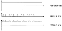
- the generated control signal is a control signal waveform shown in FIG.
- the control signal waveform When the control signal having the control signal waveform passes through the AC coupling circuit 320, the control signal waveform is synthesized with the DC voltage waveform to generate the modulated demodulated waveform of FIG. 5.
- the modulated demodulated waveform is transmitted to each outlet and an electrical supply terminal through the indoor DC voltage line 360.
- the integrated power line communication controller 242 extracts only the control signal of FIG. 5 through the AC coupling circuit 350 as a reverse process of extracting only the control signal from the modulated waveform.
- the power line communication control unit and the power line communication reception and control unit may be configured in the same configuration as the conventional example, and may be modified and configured in various other ways.
- the conventional power line communication system uses an AC voltage, but the present invention has the following advantages by using this DC power line.
- FIG. 6 is a circuit configuration diagram of the AC coupling circuit.
- the AC coupling circuit may be configured by connecting the transformer 351 to the DC power line 360 through the capacitor C 353.
- a large value of resistor R 352 may be used in parallel with capacitor C 352.
- the ratio of the magnitude of the input voltage and the output voltage to the AC signal passing through the AC coupling circuit using the L component of the transformer and the capacitor C is as follows.
- the input signal when the frequency f is high, the input signal is output to the output with very little attenuation, and when the frequency is low, the signal passing to the output is greatly attenuated.
- such an AC coupling circuit is used to attenuate much of the 60 Hz AC component of the AC voltage from the AC voltage loaded on the power line and a control signal demodulated and demodulated, and transmit information for communication.
- the control signal with a frequency value of several to several tens of KHz is attenuated and extracted little.
- the L and C values are selected to reduce the control signal less, the AC voltage of 60Hz is also attenuated, resulting in power loss.
- L and C values are selected to reduce power loss by attenuating a lot of AC voltage of 60 Hz, the magnitude of the control signal is also attenuated and reduced.
- the DC power line communication method of the present invention can reduce and extract the control signal while reducing power loss.
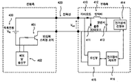
- FIG. 7 is a control block diagram of a DC voltage control unit and a power line communication unit according to an embodiment of the present invention
- FIG. 8 is a view illustrating a voltage waveform including a communication data signal output from the power line communication unit according to an embodiment of the present invention. to be.
- a circuit according to a first embodiment for explaining a power line communication method for transmitting a data signal by dividing a power transmission section in an indoor DC power system having power line communication according to the present invention includes a power supply side circuit. It consists of a load side circuit.
- the power supply side circuit includes a semiconductor switching element 401 for switching the DC power supply 400 to be connected to or disconnected from the power line 420, and a control and transmission unit 402 for controlling the semiconductor switching element 401 in a pulse width modulation method. It is composed.
- the load side circuit is connected to the power line 420 and is connected to the cathode of the diode 410 and the diode 410 for supplying current from the DC power supply 400 to the load side and preventing current from flowing in the reverse direction to smooth the voltage.
- a low pass filter consisting of an inductor 412 and a condenser 413, connected between the power supply 414 of the electrical device connected to the output of the low pass filter, the cathode of the diode 410 and the ground of the power supply 414 of the load electrical device.
- the control unit 416, and the receiving unit 415 of the load side circuit receives communication data from the voltage signal transmitted to the load side.
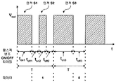
- the voltage waveform shown in FIG. 8 is a waveform of the Vout stage before passing the low pass filter using the inductor 412 and the capacitor 413 on the load side, and the power line in the indoor power system having the power line communication function of the present invention.
- a semiconductor switching is performed during a "ton2" section of a section in which a pulse voltage is "Low” in a period T of the pulse voltage.
- the device 401 is " ON “ so that the data signal " 1 " is transmitted to the load side.
- the semiconductor switching device 401 maintains the "OFF" state for the "toff3" period.
- the entire section in which power and data signals are transmitted from a power source to a load side is divided into a power transmission section and a data transmission section, and one or more data are provided in a data transmission section in which power is cut off.
- the average value or the effective value of the power supplied to the load side is maintained as it is.
- the average value of the power supplied to the load side is a value obtained by integrating the voltage or current supplied during one period and divided by the period T, in FIG. 10, when controlling the sum of ton1 and ton2 time to be ton3, area S1 and area Since the sum of S2 is equal to the area S3, the average voltage delivered to the load side on average while the data signal 1 is loaded or the data signal 0 is kept constant.
- power line communication method of the present invention only one data signal is transmitted for one period, but a plurality of data signals may be carried and transmitted for one period.
- power line communication may be performed while constantly controlling the average value or the effective value transmitted to the load side for a plurality of cycles instead of one cycle.
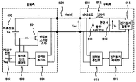
- FIG. 9 is a control block diagram of a DC voltage control unit and a power line communication unit according to another embodiment of the present invention
- FIG. 10 is a view illustrating a voltage waveform including a communication data signal output from a power line communication unit according to another embodiment of the present invention. to be.
- a circuit configuration of a second embodiment for explaining a power line communication method for transmitting a data signal by dividing a power transmission section in an indoor DC power system having power line communication according to the present invention includes a power supply side circuit and a load. It consists of a side circuit.
- the power supply side circuit includes a DC power supply 600, a semiconductor switching element 601, a control unit power supply 602, a pulse width modulation control unit 603, and a power line communication unit 604.
- the control unit power supply 602 supplies power to the power line communication unit 604 and the pulse width modulation control unit 603, and the pulse width modulation control unit 603 connects or cuts off the DC power supply 600 with the power line 620.
- the width of the voltage or current waveform supplied from the DC power supply 600 may be changed by controlling on / off of the semiconductor switching device 601.
- the power line communication unit 604 is connected to the pulse width modulation control unit 603 and transmits and receives a power line communication signal to the power line 620.
- the load side circuit includes a diode 610, a reflux diode 611, an inductor 612, a capacitor 613, an electrical device power supply 614, a power line communication unit 615, and an electrical device control unit 616.
- the diode 610 is connected to the power line 620 to transfer the power supplied from the power source to the load side and to prevent the current flowing in the reverse direction, the low pass filter composed of the inductor 612 and the capacitor 613 is a diode 610 Is connected to the cathode end of to smooth the voltage.
- the power supply 614 of the electrical device is connected to the output of the low pass filter, and the reflux diode 611 is connected between the cathode end of the diode 610 and the ground of the power supply 614 of the load electrical device to reflux the current.
- the power line communication unit 615 is connected between the anode terminal of the diode 610 and the ground of the power supply unit 614 of the load electric device, and the electric device control unit 616 receives the data transmitted through the power line communication unit 615 to control the electric device. do.
- a section toff at which power is cut off during one cycle T is determined by the power line 620 at the power supply side DC power supply 600 Vdc.
- the power line communication unit 604 divides a plurality of data signals at predetermined intervals and applies a Vsig voltage when the data signal is 1 in each section, and Vsig when 0.
- the power line 620 may be transmitted in a manner that no voltage is applied.
- a data transmission section (toff) in which power is cut off is divided into 10 sections, and the first section and the last section are spare sections for preventing noise, and the data signal in the second to ninth sections.
- the data signal may be transmitted by applying a Vsig voltage to transmit “1” and cutting off the Vsig voltage to transmit data signal “0”.
- the data transmission interval toff may be divided into various methods and periods.
- the magnitude of the data signal Vsig is smaller than the smoothed voltage V L of the load side, the current by the data signal does not flow to the load side.
- the Vsig voltage can have a large voltage value in a range smaller than the smoothed voltage of the load side, so that it is less affected by the electrical noise signal generated on the power line and does not affect the amount of power supplied to the load side. do.
- the power line communication unit 615 at the load side for receiving this data is connected to the Vout stage. Can be connected to receive data signals.
- the communication data received from the power line communication unit 615 may be received by the electric device control unit 616 to control the electric device.
- communication data may be transmitted from the power supply side to the load side, and data may be transmitted from the load side reversely to the power supply side in a data transmission section (toff) in which power (voltage or current) supplied from the power supply side is cut off.
- Toff data transmission section
- Bidirectional transmission and reception of data signals using power lines is possible.
- the state information of the electrical apparatus may be transmitted from the load side to the power side using the data transmission section in which power is cut off.
- a plurality of loads connected to a power line may transmit and receive data to each other using a data transmission section in which power is cut off.
- the sine pulse width modulation method used in the inverter has a section in which the voltage or current is low, so the principles of the present invention can be applied as it is.
- the switching frequency of the pulse modulation method is several tens of kHz
- the data transmission section can be repeated faster than the conventional method and thus have a fast data transmission period, and thus it can be applied to a field requiring real time control such as a motor control system.
- the power line communication method of the present invention has the effect of varying and controlling the power supplied to the load.
- the indoor DC power system configures the indoor wiring as a DC power system. Therefore, the use of a circuit for converting alternating current into direct current voltage can be reduced in most indoor electrical appliances, and the use of power factor improvement circuits for each electrical appliance can be reduced.
- the power factor improvement circuit has a problem in that the power factor improvement effect is inferior when the current is used at a light load flowing less in each electric product.
- the configuration of the present invention even if some electric products are light loads, the sum of the currents flowing through the various electric products is increased. Passing through the power factor improvement circuit has the advantage that the power factor improvement effect does not fall, which makes it possible to efficiently consume power and save energy.
- the power line communication method of the indoor DC power system uses a DC power line communication method that modulates and demodulates a control signal of several to several tens of kilohertz to a DC voltage. Since it can be attenuated, the control signal can be extracted with less attenuation while reducing the power loss generated in the existing AC power line communication circuit. Therefore, power consumption can be reduced without adding another circuit in the existing power line communication circuit.
- the power line communication method of the indoor DC power system by using a pulse width modulation method or a pulse period modulation method, the entire power transmission section in which the power and data supplied for driving the load is transmitted to the power transmission section and the By dividing the data into the data transmission section, the data signal is transmitted in the section where the power is cut off or "Low", so that not only does not change the average power supplied to the load side but also increases the voltage level of the data signal, The transmission error of the signal can be reduced.
- the power line communication method of the indoor DC power system according to the present invention can be controlled by varying the power supplied to the load using a pulse width modulation method or a pulse period modulation method, the switching frequency of the pulse modulation method is several tens of KHz. As it is high, it can be applied to the field that needs real time control such as motor control system because it can have a faster data transmission cycle because the data transmission section is repeated faster than the existing method. In addition, since power and data signals may be transmitted using a pulse width or a pulse period modulation method, a synchronization process may be very easy when transmitting and receiving data signals.
- the present invention improves the power factor control efficiency for indoor electrical appliances by configuring indoor wiring as a DC power system, and transmits control signals while preventing power loss when controlling and transmitting external control signals to indoor electrical equipment using a power line communication method. It can be used for indoor DC power system and its power line communication method which can improve the effect.
Landscapes
- Engineering & Computer Science (AREA)
- Power Engineering (AREA)
- Computer Networks & Wireless Communication (AREA)
- Signal Processing (AREA)
- Physics & Mathematics (AREA)
- General Physics & Mathematics (AREA)
- Automation & Control Theory (AREA)
- Cable Transmission Systems, Equalization Of Radio And Reduction Of Echo (AREA)
Abstract
본 발명은 옥내 직류전력 시스템 및 그 전력선 통신방법에 관한 것으로서, 본 시스템은, 교류 전압 선로로부터 배선되는 전력 시스템에 있어서, 교류 전압 선로로부터 일정구역에 입력된 교류(AC)전압을 직류(DC)전압으로 변환하는 통합 정류 회로부; 상기 통합 정류회로부 출력에 연결되어 부하 전체의 역률을 통합하여 개선하는 통합 역률 개선 회로부; 역률 개선 회로로부터 각 전기 콘센트 및 전기 인출단자로 배선되는 직류전압선로; 직류전압선로를 이용하여 직류 전력선통신을 수행하는 통합 전력선 통신시스템으로 구성되는 것을 특징으로 한다. 이에 의해, 옥내 배선을 직류전력 시스템으로 구성하여 옥내 전기제품에 대한 역률제어 효율을 향상시키고, 외부제어신호를 전력선 통신 방법으로 옥내 전기기기에 송수신하여 제어하는 경우 전력손실을 방지하면서 제어신호의 전송효과를 향상시킬 수 있다.
Description
본 발명은 옥내 직류전력 시스템 및 그 전력선 통신방법에 관한 것으로서, 더욱 상세하게는, 옥내 배선을 직류전력 시스템으로 구성하여 옥내 전기제품에 대한 역률제어 효율을 향상시키고, 외부제어신호를 전력선 통신 방법으로 옥내 전기기기에 송수신하여 제어하는 경우 전력손실을 방지하면서 제어신호의 전송효과를 향상시킬 수 있는 옥내 직류전력 시스템 및 그 전력선 통신방법에 관한 것이다.
도 1은 종래의 옥내 전력 시스템의 제어블럭도이다.
도 1에 도시된 바와 같이, 종래의 옥내 전력 시스템은 옥외 교류전압 선로(100)로부터 공급된 교류전원이 적산전력계(110)를 통해 옥내 교류전압 선로(120)로 공급된다. 옥내 교류전압 선로(120)의 교류전원은 옥내의 전기제품(130, 140)으로 입력된다. 여기서, 옥내 전기제품(130, 140)은 냉장고, 세탁기, 에어컨, TV, 오디오 등을 포함할 수 있다.
옥내의 전기제품(130, 140)에 내장된 장치의 전기/전자 회로부(136)는 직류전원으로 구동된다. 이에, 전기제품(130, 140)에는 옥내 교류전압 선로(120)로 공급되는 교류전원을 직류전원으로 변환하는 AC/DC변환 전력회로부(135)가 마련된다.
도 2는 종래의 전기제품 내의 AC/DC 변환 전력회로부(135)의 제어블럭도이다. 도 2에 도시된 바와 같이, AC/DC 변환 전력회로부(135)는 정류회로(131) 및 직류 전압 제어부(133)와 역률 개선을 위한 역률개선회로(132)를 포함한다.
정류회로(131) 및 직류 전압 제어부(133)는 옥내 교류전압선로(120)로부터 교류전원을 공급받아 직류전원으로 변환한다.
역률개선회로(132)는 교류를 직류로 변환할 때 발생하는 고조파 성분을 제거하여, 역률이 저하되는 것을 방지한다.
그런데, 역률개선회로(132)가 추가된 전기제품의 경우 회로에 흐르는 전류가 일정 크기 이상이 흘러야 효율적인 역률제어가 가능하다. 따라서, 전기제품이 경부하로 동작되고 있는 경우에는 전류의 양이 적어 역률제어 효율이 저하되는 문제점이 있다.
또한, 교류전원을 공급하는 종래의 옥내 전력 시스템에서 전기제품(130, 140)들의 대다수가 직류전원으로 구동되기 때문에, 각각의 전기제품(130, 140)에는 교류전원을 직류전원으로 변환하기 위한 AC/DC 변환 전력회로부(135)가 중복되어 사용되는 문제점이 있다.
한편, 외부에서 제어신호를 송수신하여 옥내 전기제품(130, 140)을 제어하는 홈 오토메이션, 혹은, 빌딩 오토메이션 기술이 개발된 바 있다. 홈 오토메이션, 혹은, 빌딩 오토메이션 시스템은 제어신호의 전달을 위해 전력선 통신 기술을 사용한다.
종래의 옥내배선 시스템은 교류전원을 이용함으로, 전력선 통신을 이용할 경우 송신측에서는 교류전원에 제어신호를 변조하여 제어 대상 전기제품에 송신한다. 이에, 수신측에서는 교류전원으로부터 제어신호만 분리하여 사용하는 방식을 사용하고 있다.
그런데, 옥내에 공급되는 60Hz의 교류전원에 수 내지 수십 KHz의 제어신호를 변복조하여 사용하는 경우, 교류전원의 전력이 손실될 수 있으며 교류전원에 포함된 제어신호를 복조해 내기가 용이하지 않다는 문제점이 있다.
본 발명은 상술한 문제점을 해결하기 위하여 안출된 것으로서, 옥내 배선을 직류전력 시스템으로 구성하여 옥내 전기제품에 대한 역률제어 효율을 향상시키고, 외부제어신호를 송수신하여 전력선 통신 방법으로 옥내 전기기기를 제어하는 경우 전력손실을 방지하면서 제어신호의 전송효과를 향상시킬 수 있는 옥내 직류전력 시스템 및 그 전력선 통신방법을 제공하는 데 그 기술적 과제가 있다.
상술한 과제를 해결하기 위한 본 발명의 옥내 직류전력시스템은, 교류 전압 선로로부터 배선되는 전력 시스템에 있어서, 교류 전압 선로로부터 일정구역에 입력된 교류(AC)전압을 직류(DC)전압으로 변환하는 통합 정류 회로부; 상기 통합 정류회로부 출력에 연결되어 부하 전체의 역률을 통합하여 개선하는 통합 역률 개선 회로부; 역률 개선 회로부로부터 각 전기 콘센트 및 전기 인출단자로 배선되는 직류전압선로; 및 상기 직류전압선로를 이용하여 직류 전력선통신을 수행하는 통합 전력선 통신시스템으로 구성된다.
여기서, 상기 통합 전력선 통신시스템은, 외부와 유무선으로 통신할 수 있는 외부제어신호 송수신부; 외부제어신호 송수신부와 연결되어 직류전압선로에 연결된 전기기기들의 제어신호 또는 상태정보를 송신 또는 수신 또는 송수신하기 위한 통합 전력선 통신(PLC) 제어부; 직류전압선로의 전기콘센트 또는 전기인출단자에 연결되어 각각의 전기기기들의 제어신호 또는 상태정보를 송신 또는 수신 또는 송수신하기 위한 개별 전력선 통신(PLC) 제어부; 및 사용자의 명령을 송수신하는 제어신호 송수신기를 포함할 수 있다.
그리고, 상기 통합 정류 회로부와 역률 개선 회로부를 거쳐 변환된 직류 전압을 제어하는 통합 직류전압 제어부를 더 포함하고, 상기 직류전압 제어부 출력으로부터 각 전기 콘센트 및 전기 인출단자로 배선되는 직류전압선로를 포함할 수 있다.
상술한 과제를 해결하기 위한 본 발명의 전력선 통신 방법은, 직류 전원에서 1개 또는 복수개의 부하 측에 공급되는 전력을 펄스폭 변조 방식 또는 펄스주기 변조방식으로 변조하는 단계; 및 상기 전력이 부하 측으로 공급되는 전력 전송 구간과 전원으로부터 부하 측으로 전력이 차단되는 데이터 전송 구간으로 분할하고, 상기 분할된 구간 중 데이터 전송 구간에 1개 또는 다수의 데이터 신호를 실어 전송하는 단계를 포함한다.
여기서, 상기 직류전압선로로부터 부하 측으로 공급되는 평균 전력이 1주기 또는 복수 개의 주기 동안 일정하게 유지되도록 상기 전력 전송 구간에 전달되는 전력 또는 상기 데이터 전송 구간에 전송되는 데이터 신호의 송신 전력을 제어하는 단계를 포함할 수 있다.
그리고, 상기 데이터 전송 구간에 전송되는 1개 또는 다수의 데이터 신호의 크기는 부하 측의 평활화된 전압의 크기보다 작을 수 있다.
또한, 상기 직류전압선로에서 공급되는 직류전원과 상기 부하의 연결이 차단되는 전압이 Low인 구간에 전송되는 1개 또는 다수의 데이터 신호의 크기가 부하 측의 평활화된 전압의 크기보다 큰 경우에, 데이터 신호를 포함한 전원으로부터 부하 측으로 공급되는 평균 전력이 1주기 또는 복수 개의 주기 동안 일정하게 유지되도록 송신 전력을 제어할 수 있다.
그리고, 상기 직류전압선로에서 상기 부하 측으로 공급되는 평균 전력의 크기를 가변시키며 제어할 수 있다.
상술한 과제를 해결하기 위한 본 발명의 전력선 통신 방법은, 직류 전원에서 1개 또는 복수개의 부하 측으로 전력을 제어하여 공급하는 펄스폭 변조 방식 또는 펄스주기 변조방식에서 전력이 부하 측으로 공급되는 전력 전송 구간과 전원으로부터 부하 측으로 전력이 차단되는 데이터 전송 구간으로 분할하고, 상기 분할된 구간 중 데이터 전송 구간에 1개 또는 다수의 데이터 신호를 실어 부하 측 상호간에 전송한다.
본 발명의 옥내 직류전력 시스템 및 그 전력선 통신방법은, 옥내 배선을 직류전력 시스템으로 구성하여 옥내 전기제품에 대한 역률제어 효율을 향상시키고, 외부제어신호를 송수신하여 전력선 통신 방법으로 옥내 전기기기를 제어하는 경우 전력손실을 방지하면서 제어신호의 전송효과를 향상시킬 수 있다.
도 1은 종래의 옥내 전력 시스템의 제어블럭도이다.
도 2는 종래의 전기제품 내의 AC/DC 변환 전력회로부의 제어블럭도이다.
도 3은 본 발명의 실시예에 따른 옥내 직류전력 시스템의 제어블럭도이다.
도 4는 본 발명의 실시예에 따른 통합전력선통신제어부의 제어블럭도이다.
도 5는 본 발명의 실시예에 따른 전력선 통신에서 사용되는 변복조된 전압 파형이다.
도 6은 본 발명의 실시예에 따른 AC 커플링 회로의 회로도이다.
도 7은 본 발명의 일 실시예에 따른 직류전압 제어부와 전력선 통신부의 제어 블럭도이다.
도 8은 본 발명의 일 실시예에 따른 통신 데이터를 포함한 전압 파형의 그래프이다.
도 9는 본 발명의 다른 실시예에 따른 직류전압 제어부와 전력선 통신부의 제어 블럭도이다.
도 10은 본 발명의 다른 실시예에 따른 통신 데이터를 포함한 전압 파형의 그래프이다.
도 3은 본 발명의 실시예에 따른 옥내 직류전력 시스템의 제어블럭도이다.
도 3에 도시된 바와 같이, 본 발명의 실시예에 따른 옥내 직류전력 시스템은, 직류전력 선로 시스템(220, 230)과 전력선 통신부(240, 260)를 포함한다.
직류전력 선로 시스템(220, 230)은 교류전원을 직류전원으로 변환하여 옥내의 전기제품(270, 280)에 공급하는 AC/DC 변환 전력회로부(220) 및 직류전압 선로(230)를 포함한다.
AC/DC 변환 전력회로부(220)는 통합정류회로(221), 통합역률개선회로(222) 및 통합직류전압제어부(223)를 포함한다.
통합정류회로(221)는 옥외 교류전압 선로(200)에서 공급되는 교류전원을 직류전원으로 변환한다. 교류를 직류로 변환하는 과정에서 전류파형이 왜곡되어 고조파 성분을 가지게 되어 역률을 저하시키게 된다. 이러한 역률 저하를 방지하기 위하여 통합정류회로(221) 출력단에는 통합역률개선회로(222)가 연결된다.
통합역률개선회로(222)는 전류의 흐름을 정현파 형태를 갖추도록 제어한다. 이에, 통합정류회로(221)에서 출력되는 직류전원의 역률을 개선하여 출력한다.
통합직류전압제어부(223)는 통합역률개선회로(222)에서 역률이 개선된 직류전원의 전압 크기를 일정한 크기로 조정한다. 통상적으로 사용되는 220V 전압의 교류가 통합정류회로(221)에서 직류로 변환되면  220V 크기를 가지는 직류전압으로 변환된다.
  220V의 직류전압은 전기적 부하의 변동에 따라 전압이 저하될 수 있기도 하고, 또 높은 직류전압은 감전의 위험성도 있다. 이에, 통합직류전압제어부(223)는 옥내 직류전압 선로(230)에 공급되는 직류전원의 전압 크기를
  220V 보다 작은 전압으로 일정하게 조정한다.
AC/DC 변환 전력회로부(220)는 직류전원을 옥내 직류전압 선로(230)로 공급한다. 옥내 직류전압 선로(230)의 직류전원은 콘센트 또는 전기인출단자(290)를 통해 옥내의 전기제품(270, 280)으로 입력된다. 여기서, 옥내 전기제품(270, 280)은 냉장고, 세탁기, 에어컨, TV, 오디오 등을 포함할 수 있다.
이러한 방식으로 옥내 직류전력 시스템을 구성하면, 각각의 전기제품(270, 280)마다 별도로 직류전압을 만들기 위하여 사용되는 정류회로부와 역률제어부를 사용하지 않아도 되므로 부품을 절감시킬 수 있다. 또한, 각각의 전기제품(270, 280)에서 역률개선회로가 동작하는 데 있어서 부하전류가 적게 흐를 때에는 역률개선효과가 떨어지는 문제를 부하전류를 모아서 역률제어를 하게 되므로 역률개선 효과를 항상 높게 유지할 수 있다.
통합직류전압제어부(223)에서 출력된 직류전압은 옥내 직류전압선로(230)를 통해 옥내의 각 콘센트 및 전기 공급 단자에 직류전압으로 공급된다. 여기서, 직류전압선로(230)는 현재 사용하고 있는 가정용 또는 빌딩용 옥내배선을 큰 변화 없이 그대로 활용할 수 있다. 즉 교류공급을 위한 2선으로 구성된 교류공급 선로를 그대로 직류전력선로(230)로 사용할 수 있다.
전력선 통신부(240, 260)는 외부의 제어신호 송신부(250)에서 전송한 제어신호를 송수신하는 외부제어신호송수신부(241)와, 송수신된 제어신호를 변복조하는 통합전력선통신제어부(242)를 포함하며, 옥내 직류전압선로(230)를 통해 전송된 제어신호를 직류전압과 분리해내는 개별전력선 통신제어부(260)를 포함한다.
제어신호 송신부(250)는 옥내 직류전압선로(230)를 통해 각 전기제품(270, 280)을 제어할 수 있는 제어신호를 송신한다. 제어신호 송신부(250)는 리모컨, 유선전화 등과 같은 유무선 통신방식을 포함한 다양한 방식으로 구성할 수 있다.
외부제어신호송수신부(241)는 제어신호 송신부(250)에서 발신된 제어신호를 수신하여 통합전력선통신제어부(242)에 전달한다. 통합전력선통신제어부(242)는 전력선 제어를 위한 제어신호를 변복조한다.
본 발명은 다양한 변경을 가할 수 있고 여러 가지 실시예를 가질 수 있는 바, 특정 실시예들을 도면에 예시하고 상세한 설명에 상세하게 설명하고자 한다. 그러나 이는 본 발명의 특정한 실시 형태에 대해 한정하려는 것이 아니며, 본 발명의 사상 및 기술 범위에 포함되는 모든 변경, 균등물 내지 대체물을 포함하는 것으로 이해되어야 한다.
이제 본 발명의 실시예에 따른 옥내 직류전력 시스템 및 그 전력선 통신방법 에 대하여 도면을 참조하여 상세하게 설명하고, 도면 부호에 관계없이 동일하거나 대응하는 구성요소는 동일한 참조 번호를 부여하고 이에 대한 중복되는 설명은 생략하기로 한다. 이하 본 발명의 바람직한 실시 예를 첨부한 도면에 의거 상세히 설명하면 다음과 같다.
도 3은 본 발명의 실시예에 따른 옥내 직류전력 시스템의 제어블럭도이다.
도 3에 도시된 바와 같이, 본 발명의 실시예에 따른 옥내 직류전력 시스템은, 직류전력 선로 시스템(220, 230)과 전력선 통신부(240, 260)를 포함한다.
직류전력 선로 시스템(220, 230)은 교류전원을 직류전원으로 변환하여 옥내의 전기제품(270, 280)에 공급하는 AC/DC 변환 전력회로부(220) 및 직류전압 선로(230)를 포함한다.
AC/DC 변환 전력회로부(220)는 통합정류회로(221), 통합역률개선회로(222) 및 통합직류전압제어부(223)를 포함한다.
통합정류회로(221)는 옥외 교류전압 선로(200)에서 공급되는 교류전원을 직류전원으로 변환한다. 교류를 직류로 변환하는 과정에서 전류파형이 왜곡되어 고조파 성분을 가지게 되어 역률을 저하시키게 된다. 이러한 역률 저하를 방지하기 위하여 통합정류회로(221) 출력단에는 통합역률개선회로(222)가 연결된다.
통합역률개선회로(222)는 전류의 흐름을 정현파 형태를 갖추도록 제어한다. 이에, 통합정류회로(221)에서 출력되는 직류전원의 역률을 개선하여 출력한다.
통합직류전압제어부(223)는 통합역률개선회로(222)에서 역률이 개선된 직류전원의 전압 크기를 일정한 크기로 조정한다. 통상적으로 사용되는 220V 전압의 교류가 통합정류회로(221)에서 직류로 변환되면  220V 크기를 가지는 직류전압으로 변환된다.
  220V의 직류전압은 전기적 부하의 변동에 따라 전압이 저하될 수 있기도 하고, 또 높은 직류전압은 감전의 위험성도 있다. 이에, 통합직류전압제어부(223)는 옥내 직류전압 선로(230)에 공급되는 직류전원의 전압 크기를
  220V 보다 작은 전압으로 일정하게 조정한다.
AC/DC 변환 전력회로부(220)는 직류전원을 옥내 직류전압 선로(230)로 공급한다. 옥내 직류전압 선로(230)의 직류전원은 콘센트 또는 전기인출단자(290)를 통해 옥내의 전기제품(270, 280)으로 입력된다. 여기서, 옥내 전기제품(270, 280)은 냉장고, 세탁기, 에어컨, TV, 오디오 등을 포함할 수 있다.
이러한 방식으로 옥내 직류전력 시스템을 구성하면, 각각의 전기제품(270, 280)마다 별도로 직류전압을 만들기 위하여 사용되는 정류회로부와 역률제어부를 사용하지 않아도 되므로 부품을 절감시킬 수 있다. 또한, 각각의 전기제품(270, 280)에서 역률개선회로가 동작하는 데 있어서 부하전류가 적게 흐를 때에는 역률개선효과가 떨어지는 문제를 부하전류를 모아서 역률제어를 하게 되므로 역률개선 효과를 항상 높게 유지할 수 있다.
통합직류전압제어부(223)에서 출력된 직류전압은 옥내 직류전압선로(230)를 통해 옥내의 각 콘센트 및 전기 공급 단자에 직류전압으로 공급된다. 여기서, 직류전압선로(230)는 현재 사용하고 있는 가정용 또는 빌딩용 옥내배선을 큰 변화 없이 그대로 활용할 수 있다. 즉 교류공급을 위한 2선으로 구성된 교류공급 선로를 그대로 직류전력선로(230)로 사용할 수 있다.
전력선 통신부(240, 260)는 외부의 제어신호 송신부(250)에서 전송한 제어신호를 송수신하는 외부제어신호송수신부(241)와, 송수신된 제어신호를 변복조하는 통합전력선통신제어부(242)를 포함하며, 옥내 직류전압선로(230)를 통해 전송된 제어신호를 직류전압과 분리해내는 개별전력선 통신제어부(260)를 포함한다.
제어신호 송신부(250)는 옥내 직류전압선로(230)를 통해 각 전기제품(270, 280)을 제어할 수 있는 제어신호를 송신한다. 제어신호 송신부(250)는 리모컨, 유선전화 등과 같은 유무선 통신방식을 포함한 다양한 방식으로 구성할 수 있다.
외부제어신호송수신부(241)는 제어신호 송신부(250)에서 발신된 제어신호를 수신하여 통합전력선통신제어부(242)에 전달한다. 통합전력선통신제어부(242)는 전력선 제어를 위한 제어신호를 변복조한다.
도 4는 본 발명의 실시예에 따른 통합전력통신제어부(242)의 제어블럭도이다.
도 4에 도시된 바와 같이, 통합전력선통신제어부(242)는 송신기(300) 및 수신기(330)와, 제어신호를 변복조하는 변복조 회로(310, 340)와 AC 커플링 회로(320, 350)를 포함한다.
송신기(300)의 송신신호가 변복조 회로(310)를 통과하면 전력선 통신을 위한 제어신호를 발생한다. 이 때, 발생하는 제어신호는 도 5에 도시된 제어신호 파형이다.
제어신호 파형을 갖는 제어신호가 AC커플링회로(320)를 거치면 직류전압파형과 합성되어 도 5의 변복조된 파형이 발생하게 된다. 이 변복조된 파형은 옥내 직류 전압선로(360)을 통하여 각 콘센트 및 전기공급 단자에 전달된다.
통합전력선통신제어부(242)는 변복조된 파형에서 제어신호만 추출해내는 역과정으로 역시 AC커플링 회로(350)를 거쳐서 도 5의 제어신호만 추출하게 된다.
본 발명에서는 예시된 기존과 동일한 구성으로 전력선 통신 제어부와 전력선 통신 수신 및 제어부를 구성할 수 있고, 기타 다양한 방법으로 이를 변형하여 구성할 수 있다. 단 기존의 전력선 통신시스템에서는 교류전압을 이용하였으나, 본 발명에서는 이를 직류전력선로를 이용하는 것으로 다음과 같은 장점을 가진다.
교류전력선로를 사용할 경우보다 본 발명의 구성에 의한 직류전력선로를 사용할 경우 AC 커플링 회로(320, 350)에서 발생하는 전력소비를 줄이면서도 제어신호가 감쇄되는 문제를 해결할 수 있다.
이러한 문제점의 발생요인을 도 6을 참조하여 상세히 설명한다.
도 6은 AC 커플링 회로의 회로 구성도이다.
도 6에 도시된 바와 같이, AC 커플링 회로는 변압기(351)를 직류전력선로(360)에 콘덴서 C(353)를 통하여 연결한 것으로 구성할 수 있다. 여기서 큰 값의 저항 R(352)을 콘덴서 C(352)와 병렬로 사용하기도 한다.
변압기의 L성분과 콘덴서 C를 이용한 AC 커플링회로를 통과하는 교류신호에 대한 입력전압과 출력전압의 크기의 비를 구하면 다음 식과 같다.
[수학식]

AC 커플링 회로에서 주파수 f가 높은 경우에는 입력된 신호가 매우 적게 감쇄가 된 상태로 출력으로 나오게 되며, 주파수가 낮은 경우에는 출력으로 통과하는 신호가 크게 감쇄된다. 종래와 같은 교류전력선을 이용한 전력선 통신회로에서는 이러한 AC 커플링 회로를 이용하여, 전력선에 실린 교류전압과 제어신호가 변복조된 파형으로부터 교류전압의 60Hz 교류성분을 많이 감쇄시키고, 통신으로 보내기 위한 정보를 담은 수 내지 수십 KHz의 주파수 값을 가진 제어신호는 적게 감쇄하여 추출하여 낸다. 이 때 제어신호를 적게 감쇄시키기 위하여 L, C 값을 선정할 경우에는 60Hz의 교류전압도 감쇄되는 정도가 적어져 전력손실을 가져오게 된다. 반대로 전력손실을 줄이려 60Hz의 교류전압을 많이 감쇄시켜 없애버리려고 L, C값을 선정하면, 제어신호의 크기도 함께 감쇄되어 줄어들게 되는 문제점을 가지고 있다.
그러나, 본 발명에서의 구성과 같이 직류전력선로(360)를 이용한 전력선 통신을 할 경우, 직류전압에 수 내지 수십 KHz의 제어신호를 변복조하여 사용하면, AC 커플링 회로를 구성할 때 식에서 볼 수 있듯이 직류전압성분은 확실하게 감쇄시킬 수 있는 장점을 가지게 된다. 따라서 교류전력선 통신에서 사용한 동일한 AC 커플링 회로를 사용할 경우 본 발명에 속한 직류전력선통신방식은 전력손실을 줄이면서도 제어신호를 적게 감쇄시키며 추출해낼 수 있다.
도 7은 본 발명의 일 실시예에 따른 직류전압 제어부와 전력선 통신부의 제어 블럭도이고, 도 8은 본 발명의 일 실시예에 따른 전력선 통신부가 출력하는 통신 데이터 신호를 포함한 전압 파형을 도시한 도면이다.
도 7에 도시된 바와 같이, 본 발명의 전력선 통신을 가지는 옥내 직류전력시스템에서 전력전송구간을 분할하여 데이터 신호를 전송하는 전력선 통신방법을 설명하기 위한 제1 실시 예에 따른 회로는 전원 측 회로와 부하 측 회로로 구성된다.
전원 측 회로는 직류전원(400)을 전력선(420)과 연결 또는 차단하도록 스위칭하는 반도체 스위칭 소자(401)와, 반도체 스위칭 소자(401)를 펄스폭 변조방식으로 제어하는 제어 및 송신부(402)로 구성된다.
부하 측 회로는 전력선(420)에 연결되어 직류전원(400)으로부터 전류를 부하 측으로 공급받고 역방향으로 전류가 흐르는 것을 방지하는 다이오드(410), 다이오드(410)의 캐소드 단에 연결되어 전압을 평활화시키는 인덕터(412)와 콘덴서(413)로 구성된 저역 통과 필터, 저역 통과 필터의 출력단에 연결된 전기장치의 전원부(414), 다이오드(410)의 캐소드 단과 부하 전기장치의 전원부(414)의 그라운드 사이에 접속되어 전류를 환류시키는 환류 다이오드(411), 다이오드(410) 애노드 단과 부하 전기장치의 전원부의 그라운드 사이에 접속된 수신부(415) 및 수신부(415)로부터 통신 데이터 신호를 받아 전기장치를 제어하는 전기장치제어부(416)로 구성되고, 부하 측 회로의 수신부(415)는 부하 측으로 전달된 전압 신호로부터 통신 데이터를 수신한다.
도 8에 도시한 전압 파형은 부하 측의 인덕터(412)와 콘덴서(413)를 이용한 저역통과필터를 거치기 전인 Vout단의 파형을 측정한 것으로, 본 발명의 전력선 통신기능을 가지는 옥내 전력시스템에서 전력선 통신방법을 구현하는 제1 실시 예에 따른 전력전송구간을 분할하여 데이터 신호를 전송하는 전력선 통신방법은 펄스 전압의 주기(T) 중 펄스 전압이 "Low"인 구간 중 "ton2" 구간 동안 반도체 스위칭 소자(401)를 "ON"시켜 데이터 신호 "1"이 부하 측으로 전달되도록 하는 방법이다.
상기의 경우 데이터 신호가 "0"인 경우 "toff3" 구간 동안 반도체 스위칭 소자(401)는 "OFF" 상태를 유지한다.
본 발명에 따른 전력선 통신방식은 전원으로부터 부하 측으로 전력과 데이터 신호가 전송되는 전체 구간을 전력 전송 구간과 데이터 전송 구간으로 분리하여 분리된 구간 중 전력이 차단된 데이터 전송 구간에 1개 또는 다수의 데이터 신호를 실어 전송하는 방법으로, 부하 측으로 공급되는 전력의 평균값 또는 실효값을 그대로 유지된다.
부하 측으로 공급되는 전력의 평균값은 1주기 동안 공급된 전압 또는 전류를 적분하여 주기(T)로 나눈 값을 의미하므로, 도 10에서, ton1과 ton2 시간의 합이 ton3가 되도록 제어하면 면적 S1과 면적 S2의 합이 면적 S3가 되므로 데이터 신호가 1 이 실린 동안이나 데이터 신호가 0 이 실린 동안 부하 측에 평균적으로 전달되는 평균전압은 일정하게 유지할 수 있다.
본 발명의 전력선 통신방법에 따른 제1 실시 예에서, 1주기 동안 1개의 데이터 신호만 전송되었지만, 1주기 동안 복수 개의 데이터 신호를 실어 전송할 수 있다. 또한, 동일한 방법으로 1주기가 아닌 복수 개의 주기 동안 부하 측으로 전송되는 평균값 또는 실효값을 일정하게 제어하며 전력선 통신을 수행할 수 있다.
도 9는 본 발명의 다른 실시예에 따른 직류전압 제어부와 전력선 통신부의 제어 블럭도이고, 도 10은 본 발명의 다른 실시예에 따른 전력선 통신부가 출력하는 통신 데이터 신호를 포함한 전압 파형을 도시한 도면이다.
도 9에 도시한 바와 같이, 본 발명의 전력선 통신을 가지는 옥내 직류전력시스템에서 전력전송구간을 분할하여 데이터 신호를 전송하는 전력선 통신방법을 설명하기 위한 제2 실시 예의 회로 구성은 전원 측 회로와 부하 측 회로로 구성된다.
전원 측 회로는 직류전원(600), 반도체 스위칭 소자(601), 제어부 전원(602), 펄스폭 변조 제어부(603) 및 전력선 통신부(604)를 포함한다.
제어부 전원(602)은 전력선 통신부(604)와 펄스폭변조제어부(603)에 전원을 공급하고, 펄스폭 변조 제어부(603)는 직류전원(600)을 전력선(620)과 연결 또는 차단할 수 있게 하는 반도체 스위칭 소자(601)의 온/오프 제어하여 직류전원(600)으로부터 공급되는 전압 또는 전류 파형의 폭을 변화시킬 수 있다.
전력선 통신부(604)는 펄스폭 변조제어부(603)와 연결되고 전력선(620)에 전력선 통신신호를 송수신한다.
부하 측 회로는 다이오드(610), 환류다이오드(611), 인덕터(612), 콘덴서(613), 전기장치 전원부(614), 전력선 통신부(615) 및 전기장치 제어부(616)을 포함한다.
다이오드(610)는 전력선(620)에 연결되어 전원으로부터 공급되는 전력을 부하 측으로 전달하고 역방향으로 전류가 흐르는 것을 방지하며, 인덕터(612)와 콘덴서(613)로 구성된 저역통과필터는 다이오드(610)의 캐소드 단에 연결되어 전압을 평활화시킨다.
전기장치의 전원부(614)는 저역통과 필터의 출력단에 연결되고, 환류다이오드(611)는 다이오드(610)의 캐소드 단과 부하 전기장치의 전원부(614)의 그라운드 사이에 접속되어 전류를 환류시킨다.
전력선 통신부(615)는 다이오드(610) 애노드 단과 부하 전기장치의 전원부(614)의 그라운드 사이에 접속되고, 전기장치 제어부(616)는 전력선 통신부(615)를 통하여 송신한 데이터를 받아 전기장치를 제어한다.
도 9의 회로에서 직류전원(600)을 반도체 스위칭 소자(601)로 스위칭할 때, 1주기(T) 동안 전력이 차단되는 구간(toff)은 전력선(620)이 전원 측 직류전원(600) Vdc와 분리되고, 전력선(620)에 통신 데이터를 싣기 위하여 전력선 통신부(604)에서 복수 개의 데이터 신호를 toff 시간을 정해진 간격으로 나누어 각 구간에서 데이터 신호를 1인 경우 Vsig 전압을 가하고, 0 인 경우 Vsig 전압을 가하지 않는 방식으로 전력선(620)에 실어 전송할 수 있다.
도 10에 도시한 바와 같이, 전력이 차단되는 데이터 전송 구간(toff)은 10개의 구간으로 분할하고 첫 번째 구간과 마지막 구간은 잡음을 방지하기 위한 여유 구간으로 두고 2번째부터 9번째 구간에 데이터 신호 "1"을 전송하기 위해 Vsig 전압을 인가하고, 데이터 신호 "0"을 전송하기 위해 Vsig 전압을 차단하는 방법으로 데이터 신호를 전송할 수 있다.
데이터 전송 구간(toff)은 다양한 방법과 주기로 분할될 수 있으며, 데이터 신호의 크기(Vsig)가 부하 측의 평활화된 전압(VL)보다 작으면 데이터 신호에 의한 전류는 부하 측에 흐르지 않게 된다.
즉, Vsig 전압은 부하 측의 평활화된 전압보다 작은 범위에서 얼마든지 큰 전압값을 가질 수 있게 되어 전력선에 발생하는 전기적 잡음신호에 영향을 적게 받을 뿐만 아니라 부하 측에 공급되는 전력량에도 영향을 주지 않게 된다.
또한, Vsig 전압이 평활화된 전압보다 큰 경우에도 1주기 동안 데이터 신호 파형들의 면적 합과 전력공급 전압의 ton 기간 동안의 면적의 합이 항상 일정하도록 제어하면 공급하는 전압의 평균값 또는 실효값을 그대로 유지하며 전력선 통신을 할 수 있다.
전송된 데이터 신호의 파형은 부하 측의 인덕터(612)와 콘덴서(613)를 이용한 저역통과필터를 거치기 전인 Vout 단에 나타나므로 이 데이터를 수신하기 위한 부하 측의 전력선통신부(615)를 Vout 단에 연결하여 데이터 신호를 수신할 수 있다. 또한, 전력선통신부(615)에서 수신된 통신 데이터는 전기장치제어부(616)에서 받아 전기장치를 제어할 수 있다.
상기에서 설명한 방식으로 전원 측에서 부하 측으로 통신 데이터를 전송할 수도 있고, 전원 측에서 공급되는 전력(전압 또는 전류)가 차단되는 데이터 전송 구간(toff)에서 역방향인 부하 측에서 전원 측으로 데이터를 전송할 수도 있으므로 전력선을 이용한 데이터 신호의 양방향 송수신이 가능하다.
즉, 전력이 차단되는 데이터 전송 구간을 이용하여 부하 측으로부터 전원 측으로 전기장치의 상태 정보 등을 전송할 수 있다. 또한 전력이 차단되는 데이터 전송구간을 이용하여 전력선에 연결된 복수개의 부하들 간에도 서로 데이터를 송수신할 수 있다.
상기에서 설명한 도 7 및 도 9에서 펄스폭 변조방식 대신 펄스주기 변조방식을 사용하는 경우에도 전압 또는 전류가 Low인 구간 또는 전력이 차단되는 구간이 존재하므로 본 발명의 원리를 그대로 적용할 수 있다.
또한, 인버터에 사용하는 정현 펄스폭 변조방식에도 전압 또는 전류가 Low인 구간이 존재하므로 본 발명의 원리를 그대로 적용할 수 있다.
또한 펄스변조방식의 스위칭 주파수가 수십 kHz로 높아서 기존의 방식에 비하여 데이터 전송구간이 빠르게 반복되어 빠른 데이터 전송주기를 가질 수 있으므로 모터제어 시스템 등과 같이 실시간 제어가 필요한 분야에 적용할 수 있다.
또한 펄스폭 변조 방식 또는 펄스주기 변조방식을 사용하므로, 본 발명의 전력선 통신방법에서는 부하에 공급되는 전력도 가변시키며 제어할 수 있는 효과가 있다.
이상 설명한 바와 같이, 본 발명에 따른 옥내 직류전력 시스템은, 옥내 배선을 직류전력 시스템으로 구성한다. 이에, 옥내의 대다수 전기제품들에서 교류를 직류전압으로 변환하는 회로의 중복되는 사용을 줄일 수 있으며, 각 전기제품마다 역률개선회로를 중복되게 사용하는 것을 줄일 수 있다. 역률개선회로는 각 전기제품에서 전류가 적게 흐르는 경부하로 사용할 때에는 역률개선 효과가 떨어지는 문제점이 있으나, 본 발명의 구성에 의하면, 일부의 전기제품이 경부하 일지라도 여러 전기제품에 흐르는 전류를 합한 전류가 역률개선회로를 통과하게 되므로 역률개선효과가 떨어지지 않는 장점을 가지게 되고, 이는 전력소비를 효율적으로 할 수 있게 하여 에너지를 절감할 수 있다.
그리고, 본 발명에 따른 옥내 직류전력 시스템의 전력선 통신방법은, 직류전압에 수 내지 수십 KHz의 제어신호를 변복조하는 직류전력선 통신방식을 사용하면, AC 커플링 회로를 구성할 때 직류전압성분을 많이 감쇄시킬 수 있으므로 기존의 교류전력선 통신회로에서 발생하는 전력손실을 줄이면서도 제어신호를 적게 감쇄시키며 추출해낼 수 있다. 따라서 기존의 전력선 통신회로에서 다른 회로를 추가하지 않아도 전력소비를 줄일 수 있다.
한편, 본 발명에 따른 옥내 직류전력 시스템의 전력선 통신방법은, 펄스폭변조방식 또는 펄스주기 변조방식을 이용하여, 부하 구동을 위해 공급되는 전력과 데이터가 전송되는 전체 전력 전송 구간을 전력 전송 구간과 데이터 전송 구간으로 분할하여 전력이 차단되거나 "Low"인 구간에서 데이터 신호를 실어 전송함으로써 부하 측으로 공급되는 평균 전력의 변화를 발생시키지 않을 뿐만 아니라 데이터 신호의 전압 크기를 높일 수 있고 전기적 잡음에 의한 데이터 신호의 전송 오류를 줄일 수 있다.
또한, 본 발명에 따른 옥내 직류전력 시스템의 전력선 통신방법은, 펄스폭 변조 방식 또는 펄스주기 변조방식을 사용하여 부하에 공급되는 전력도 가변시키며 제어할 수 있으며, 펄스변조방식의 스위칭 주파수가 수십 KHz로 높아서 기존의 방식에 비하여 데이터 전송구간이 빠르게 반복되어 빠른 데이터 전송주기를 가질 수 있으므로 모터제어 시스템 등과 같이 실시간 제어가 필요한 분야에 적용할 수 있다. 그리고, 펄스폭 또는 펄스주기 변조방식을 이용하여 전력 및 데이터 신호를 전송할 수 있으므로 데이터 신호 송수신 시, 동기화 과정이 매우 용이한 효과가 있다.
상술한 바와 같이, 본 발명의 바람직한 실시 예에 대해 설명하였으나, 본 발명은 상술한 특정의 바람직한 실시예에 한정되지 아니하며, 청구범위에서 청구하는 본 발명의 요지를 벗어남이 없이 당해 발명이 속하는 기술분야에서 통상의 지식을 가진 자라면 누구든지 다양한 변형실시가 가능한 것은 물론이고, 그와 같은 변경은 청구범위 기재의 기술적 범위 내에 포함된다 할 수 있다.
본 발명은 옥내 배선을 직류전력 시스템으로 구성하여 옥내 전기제품에 대한 역률제어 효율을 향상시키고, 외부제어신호를 전력선 통신 방법으로 옥내 전기기기에 송수신하여 제어하는 경우 전력손실을 방지하면서 제어신호의 전송효과를 향상시킬 수 있는 옥내 직류전력 시스템 및 그 전력선 통신방법에 이용할 수 있다.
Claims (9)
- 교류 전압 선로로부터 배선되는 전력 시스템에 있어서,교류 전압 선로로부터 일정구역에 입력된 교류(AC)전압을 직류(DC)전압으로 변환하는 통합 정류 회로부;상기 통합 정류회로부 출력에 연결되어 부하 전체의 역률을 통합하여 개선하는 통합 역률 개선 회로부;역률 개선 회로부로부터 각 전기 콘센트 및 전기 인출단자로 배선되는 직류전압선로; 및상기 직류전압선로를 이용하여 직류 전력선통신을 수행하는 통합 전력선 통신시스템으로 구성되는 것을 특징으로 하는 전력선통신 기능을 가지는 옥내 직류전력시스템.
- 제 1항에 있어서, 통합 전력선 통신시스템은,외부와 유무선으로 통신할 수 있는 외부제어신호 송수신부;외부제어신호 송수신부와 연결되어 직류전압선로에 연결된 전기기기들의 제어신호 또는 상태정보를 송신 또는 수신 또는 송수신하기 위한 통합 전력선 통신(PLC) 제어부;직류전압선로의 전기콘센트 또는 전기인출단자에 연결되어 각각의 전기기기들의 제어신호 또는 상태정보를 송신 또는 수신 또는 송수신하기 위한 개별 전력선 통신(PLC) 제어부; 및사용자의 명령을 송수신하는 제어신호 송수신기를 포함하는 것을 특징으로 하는 전력선통신 기능을 가지는 옥내 직류전력시스템.
- 제1항에 있어서,상기 통합 정류 회로부와 역률 개선 회로부를 거쳐 변환된 직류 전압을 제어하는 통합 직류전압 제어부를 더 포함하고,상기 직류전압 제어부 출력으로부터 각 전기 콘센트 및 전기 인출단자로 배선되는 직류전압선로를 포함하는 전력선통신 기능을 가지는 옥내 직류전력시스템.
- 전원에서 1개 또는 복수개의 부하 측에 공급되는 전력을 펄스폭 변조 방식 또는 펄스주기 변조방식으로 변조하는 단계;상기 전력이 부하 측으로 공급되는 전력 전송 구간과 전원으로부터 부하 측으로 전력이 차단되는 데이터 전송 구간으로 분할하고, 상기 분할된 구간 중 데이터 전송 구간에 1개 또는 다수의 데이터 신호를 실어 전송하는 단계를 포함하는 전력선 통신 방법.
- 제4항에 있어서,상기 전원으로부터 부하 측으로 공급되는 평균 전력이 1주기 또는 복수 개의 주기 동안 일정하게 유지되도록 상기 전력 전송 구간에 전달되는 전력 또는 상기 데이터 전송 구간에 전송되는 데이터 신호의 송신 전력을 제어하는 단계를 포함하는 것을 특징으로 하는 전력선 통신 방법.
- 제4항에 있어서,상기 데이터 전송 구간에 전송되는 1개 또는 다수의 데이터 신호의 크기는 부하 측의 평활화된 전압의 크기보다 작은 것을 특징으로 하는 전력선 통신 방법.
- 제4항에 있어서,상기 전원과 부하의 연결이 차단되는 전압이 Low인 구간에 전송되는 1개 또는 다수의 데이터 신호의 크기가 부하 측의 평활화된 전압의 크기보다 큰 경우에, 데이터 신호를 포함한 전원으로부터 부하 측으로 공급되는 평균 전력이 1주기 또는 복수 개의 주기 동안 일정하게 유지되도록 송신 전력을 제어하는 것을 특징으로 하는 전력선 통신 방법.
- 제4항에 있어서,상기 전원으로부터 상기 부하 측으로 공급되는 평균 전력의 크기를 가변 시키며 제어하는 것을 특징으로 하는 전력선 통신 방법.
- 전원에서 1개 또는 복수개의 부하 측으로 전력을 제어하여 공급하는 펄스폭 변조 방식 또는 펄스주기 변조방식에서 전력이 부하 측으로 공급되는 전력 전송 구간과 전원으로부터 부하 측으로 전력이 차단되는 데이터 전송 구간으로 분할하고, 상기 분할된 구간 중 데이터 전송 구간에 1개 또는 다수의 데이터 신호를 실어 부하 측 상호간에 전송하는 전력선 통신 방법.
Applications Claiming Priority (2)
| Application Number | Priority Date | Filing Date | Title |
|---|---|---|---|
| KR10-2010-0040666 | 2010-04-30 | ||
| KR1020100040666A KR20110121187A (ko) | 2010-04-30 | 2010-04-30 | 전력선 통신기능을 가지는 옥내 직류전력 시스템 |
Publications (2)
| Publication Number | Publication Date |
|---|---|
| WO2011136591A2 true WO2011136591A2 (ko) | 2011-11-03 |
| WO2011136591A3 WO2011136591A3 (ko) | 2012-03-22 |
Family
ID=44862070
Family Applications (1)
| Application Number | Title | Priority Date | Filing Date |
|---|---|---|---|
| PCT/KR2011/003167 Ceased WO2011136591A2 (ko) | 2010-04-30 | 2011-04-28 | 옥내 직류전력 시스템 및 그 전력선 통신방법 |
Country Status (2)
| Country | Link |
|---|---|
| KR (1) | KR20110121187A (ko) |
| WO (1) | WO2011136591A2 (ko) |
Cited By (5)
| Publication number | Priority date | Publication date | Assignee | Title |
|---|---|---|---|---|
| EP2854300A1 (de) * | 2013-09-30 | 2015-04-01 | Moog Unna GmbH | Umrichtersystem, Pitchsystem mit einem Umrichtersystem und Verfahren zum Betrieb eines Umrichtersystems |
| CN106655489A (zh) * | 2016-10-08 | 2017-05-10 | 广州霍斯通电气股份有限公司 | 中压负荷开关柜的三遥控制装置 |
| US9997958B2 (en) | 2013-03-20 | 2018-06-12 | Philips Lighting Holding B.V. | DC power distribution system |
| CN117674060A (zh) * | 2023-12-04 | 2024-03-08 | 广州艾瑞思智能科技有限公司 | 一种交变直流通讯系统 |
| CN118004850A (zh) * | 2022-11-08 | 2024-05-10 | 三菱电机楼宇解决方案株式会社 | 电梯层站电源装置和电力供给方法 |
Families Citing this family (1)
| Publication number | Priority date | Publication date | Assignee | Title |
|---|---|---|---|---|
| CN115102216B (zh) * | 2022-07-27 | 2024-05-14 | 上海交通大学 | 一种交直流混合供电电路 |
Family Cites Families (6)
| Publication number | Priority date | Publication date | Assignee | Title |
|---|---|---|---|---|
| KR100283414B1 (ko) * | 1995-04-22 | 2001-03-02 | 이종수 | 안정기의 교류/직류변환기 공용화 장치 |
| JP2002354666A (ja) * | 2001-05-22 | 2002-12-06 | Electric Power Dev Co Ltd | 発電設備を配電線に系統連系する装置 |
| JP2003204682A (ja) * | 2002-01-08 | 2003-07-18 | Nippon Telegr & Teleph Corp <Ntt> | 直流配電システム |
| KR20060019717A (ko) * | 2004-08-30 | 2006-03-06 | 한국전기연구원 | 전력계통 내의 단위 구간에 대한 직류 전원 공급 시스템 |
| JP2007228440A (ja) * | 2006-02-24 | 2007-09-06 | Mitsubishi Materials Corp | 電源組込型電力線通信装置、電力線通信方法及び電力線通信プログラム |
| KR101445181B1 (ko) * | 2007-05-08 | 2014-10-06 | 주식회사 필룩스 | 기기의 제어장치 및 그 제어방법 |
-
2010
- 2010-04-30 KR KR1020100040666A patent/KR20110121187A/ko not_active Ceased
-
2011
- 2011-04-28 WO PCT/KR2011/003167 patent/WO2011136591A2/ko not_active Ceased
Cited By (6)
| Publication number | Priority date | Publication date | Assignee | Title |
|---|---|---|---|---|
| US9997958B2 (en) | 2013-03-20 | 2018-06-12 | Philips Lighting Holding B.V. | DC power distribution system |
| EP2854300A1 (de) * | 2013-09-30 | 2015-04-01 | Moog Unna GmbH | Umrichtersystem, Pitchsystem mit einem Umrichtersystem und Verfahren zum Betrieb eines Umrichtersystems |
| CN106655489A (zh) * | 2016-10-08 | 2017-05-10 | 广州霍斯通电气股份有限公司 | 中压负荷开关柜的三遥控制装置 |
| CN106655489B (zh) * | 2016-10-08 | 2023-04-07 | 广州霍斯通电气股份有限公司 | 中压负荷开关柜的三遥控制装置 |
| CN118004850A (zh) * | 2022-11-08 | 2024-05-10 | 三菱电机楼宇解决方案株式会社 | 电梯层站电源装置和电力供给方法 |
| CN117674060A (zh) * | 2023-12-04 | 2024-03-08 | 广州艾瑞思智能科技有限公司 | 一种交变直流通讯系统 |
Also Published As
| Publication number | Publication date |
|---|---|
| KR20110121187A (ko) | 2011-11-07 |
| WO2011136591A3 (ko) | 2012-03-22 |
Similar Documents
| Publication | Publication Date | Title |
|---|---|---|
| TWI475816B (zh) | 電力線通信裝置、附帶通信功能之電源電路、電氣機器及控制監視系統 | |
| US6842668B2 (en) | Remotely accessible power controller for building lighting | |
| WO2011136591A2 (ko) | 옥내 직류전력 시스템 및 그 전력선 통신방법 | |
| KR101278125B1 (ko) | 전력선 통신에서 교류 전압 감지를 이용한 디밍 제어 장치 | |
| WO2014109584A1 (ko) | 전력선 통신에서 상용전원의 진폭변화를 이용한 디밍제어 장치 및 방법 | |
| KR102291764B1 (ko) | GaN FET이 채용된 저전력 PFC 전원부 및 앰프출력부 통합모듈 및 그 통합모듈이 구비된 전관방송 시스템용 장비 | |
| CN217037504U (zh) | Led调光电路及调光led灯 | |
| WO2015119382A1 (ko) | 대기 전력 절감 회로 | |
| CN114340077A (zh) | Led调光电路、调光led灯及基于led调光电路的led调光方法 | |
| TW201351903A (zh) | 電力線通訊控制系統 | |
| WO2021033976A1 (ko) | 극성전환 전력선 통신 | |
| WO2022108339A1 (ko) | Thd 및 emi가 개선된 조명 제어장치용 스마트 컨버터 및 이를 포함하는 조명 제어장치 | |
| US8072786B2 (en) | Power supply module with power saving mode | |
| WO2019124797A1 (ko) | 간섭 소음 제거 및 출력 제어 기능이 개선된 유도 가열 장치 | |
| WO2020027374A1 (ko) | 단상 절연형 역률개선용 세픽 컨버터 | |
| WO2016153208A1 (ko) | 무선 전력 수신기 | |
| CN111404580B (zh) | 一种电力线功率信号复合传输系统及传输方法 | |
| CN220292219U (zh) | 一种直流集中照明配电系统 | |
| KR101137824B1 (ko) | 전력선 통신을 이용한 조명 제어 시스템 및 그 제어방법 | |
| CN210780235U (zh) | 用于照明设备的无线充电系统 | |
| CN210405304U (zh) | 高压电力线载波耦合系统 | |
| JP3328227B2 (ja) | データ通信システム | |
| CN203364345U (zh) | 变频空调器的通信电路及变频空调器 | |
| CN218416747U (zh) | 一种高压直流集中供电照明系统 | |
| KR20140030847A (ko) | 직류전원 발생장치 및 발생 방법 |
Legal Events
| Date | Code | Title | Description |
|---|---|---|---|
| 121 | Ep: the epo has been informed by wipo that ep was designated in this application |
Ref document number: 11775296 Country of ref document: EP Kind code of ref document: A2 |
|
| NENP | Non-entry into the national phase |
Ref country code: DE |
|
| 122 | Ep: pct application non-entry in european phase |
Ref document number: 11775296 Country of ref document: EP Kind code of ref document: A2 |