WO2011142182A1 - 自動分析システムおよび装置管理サーバ - Google Patents
自動分析システムおよび装置管理サーバ Download PDFInfo
- Publication number
- WO2011142182A1 WO2011142182A1 PCT/JP2011/057422 JP2011057422W WO2011142182A1 WO 2011142182 A1 WO2011142182 A1 WO 2011142182A1 JP 2011057422 W JP2011057422 W JP 2011057422W WO 2011142182 A1 WO2011142182 A1 WO 2011142182A1
- Authority
- WO
- WIPO (PCT)
- Prior art keywords
- sample
- loading
- unloading
- analysis system
- time
- Prior art date
- Legal status (The legal status is an assumption and is not a legal conclusion. Google has not performed a legal analysis and makes no representation as to the accuracy of the status listed.)
- Ceased
Links
Images


Classifications
-
- G—PHYSICS
- G06—COMPUTING OR CALCULATING; COUNTING
- G06Q—INFORMATION AND COMMUNICATION TECHNOLOGY [ICT] SPECIALLY ADAPTED FOR ADMINISTRATIVE, COMMERCIAL, FINANCIAL, MANAGERIAL OR SUPERVISORY PURPOSES; SYSTEMS OR METHODS SPECIALLY ADAPTED FOR ADMINISTRATIVE, COMMERCIAL, FINANCIAL, MANAGERIAL OR SUPERVISORY PURPOSES, NOT OTHERWISE PROVIDED FOR
- G06Q10/00—Administration; Management
- G06Q10/06—Resources, workflows, human or project management; Enterprise or organisation planning; Enterprise or organisation modelling
- G06Q10/063—Operations research, analysis or management
- G06Q10/0631—Resource planning, allocation, distributing or scheduling for enterprises or organisations
- G06Q10/06311—Scheduling, planning or task assignment for a person or group
- G06Q10/063114—Status monitoring or status determination for a person or group
-
- G—PHYSICS
- G01—MEASURING; TESTING
- G01N—INVESTIGATING OR ANALYSING MATERIALS BY DETERMINING THEIR CHEMICAL OR PHYSICAL PROPERTIES
- G01N35/00—Automatic analysis not limited to methods or materials provided for in any single one of groups G01N1/00 - G01N33/00; Handling materials therefor
- G01N35/00584—Control arrangements for automatic analysers
- G01N35/0092—Scheduling
- G01N35/0095—Scheduling introducing urgent samples with priority, e.g. Short Turn Around Time Samples [STATS]
-
- G—PHYSICS
- G16—INFORMATION AND COMMUNICATION TECHNOLOGY [ICT] SPECIALLY ADAPTED FOR SPECIFIC APPLICATION FIELDS
- G16H—HEALTHCARE INFORMATICS, i.e. INFORMATION AND COMMUNICATION TECHNOLOGY [ICT] SPECIALLY ADAPTED FOR THE HANDLING OR PROCESSING OF MEDICAL OR HEALTHCARE DATA
- G16H10/00—ICT specially adapted for the handling or processing of patient-related medical or healthcare data
- G16H10/40—ICT specially adapted for the handling or processing of patient-related medical or healthcare data for data related to laboratory analysis, e.g. patient specimen analysis
-
- G—PHYSICS
- G01—MEASURING; TESTING
- G01N—INVESTIGATING OR ANALYSING MATERIALS BY DETERMINING THEIR CHEMICAL OR PHYSICAL PROPERTIES
- G01N35/00—Automatic analysis not limited to methods or materials provided for in any single one of groups G01N1/00 - G01N33/00; Handling materials therefor
- G01N35/02—Automatic analysis not limited to methods or materials provided for in any single one of groups G01N1/00 - G01N33/00; Handling materials therefor using a plurality of sample containers moved by a conveyor system past one or more treatment or analysis stations
- G01N35/04—Details of the conveyor system
- G01N2035/046—General conveyor features
- G01N2035/0462—Buffers [FIFO] or stacks [LIFO] for holding carriers between operations
-
- G—PHYSICS
- G01—MEASURING; TESTING
- G01N—INVESTIGATING OR ANALYSING MATERIALS BY DETERMINING THEIR CHEMICAL OR PHYSICAL PROPERTIES
- G01N35/00—Automatic analysis not limited to methods or materials provided for in any single one of groups G01N1/00 - G01N33/00; Handling materials therefor
- G01N35/10—Devices for transferring samples or any liquids to, in, or from, the analysis apparatus, e.g. suction devices, injection devices
- G01N2035/1027—General features of the devices
- G01N2035/1032—Dilution or aliquotting
Definitions
- the present invention relates to an automatic analysis system in a clinical test, and more particularly to a technique for testing a highly urgent sample within a predetermined time.
- An automatic analysis system that automates the inspection work of specimens is a group of devices that perform preprocessing such as centrifugation, opening, and dispensing, a group of analyzers that perform analysis according to test items, and a device that performs postprocessing such as classification, storage, and disposal Group, a transport device that forms a transport path connecting those devices, a server that manages the device group, a server that manages the inspection information, an inspection engineer in charge of inspection work requests an inspection, manages inspection results, It consists of an operation terminal that performs settings, and automatically inspects various specimens that have been input in response to a test request.
- a plurality of input ports having different priorities are provided in an input device into which a sample is input, and an emergency sample input to an input port having a high priority is processed in preference to a general sample. Be able to.
- Patent Document 1 since only the technique of Patent Document 1 cannot predict interference between samples downstream of the conveyance path, for example, there is a sample having a higher dispensing ratio than usual, or a sample that needs to pass through a plurality of devices.
- traffic jams may occur in the vicinity of the direction changing device installed before and after the dispensing device, or at the branch point or junction of the conveyance path.
- the dispensing device and the analysis device are connected downstream of a centrifuge that processes several tens of samples at a time. Samples input after several tens of samples input for processing are put on hold until processing of several tens of samples input before that is completed. Therefore, even for an urgent sample, the TAT may increase in units of several minutes required for one centrifugation depending on the timing of insertion.
- the essential problem of such a conventional technology is that the presence of the sample obtained from the sensor installed in the system alone affects how the input sample affects the subsequent occurrence of congestion, and how much congestion occurs. It is that we do not know what happens.
- the present invention has been made in view of the above problems, and an object of the present invention is to accurately predict the stagnation state of a sample in the system and prevent an increase in TAT of an emergency sample.
- the present invention is an automatic analysis system having a plurality of apparatuses that perform processing of each process necessary for specimen inspection, and the order of loading and unloading specimens that have been input,
- a tracking unit that identifies the current position of each sample in each device, using information on a predetermined transport path according to the examination content and a signal from a sample detection sensor installed in each unit in each device, By simulating the operation of each device when the given loading / unloading plan is applied with the current position of each sample as an initial state using the operation model of each device, each device of each sample Create a simulation unit that estimates the residence time in each waiting area in the system, and an initial loading / unloading plan that allows the emergency sample to be loaded / unloaded preferentially over the general sample.
- a loading / unloading plan unit that creates a final loading / unloading plan by correcting the loading / unloading timing or loading / unloading sequence of samples other than the sample.
- the present invention it is possible to accurately predict the stagnation state of a sample in the system, and to prevent an increase in TAT of an urgent sample by adjusting the sample loading / unloading timing and the loading / unloading sequence in each apparatus. it can.
- FIG. 1 It is a figure which shows the example of the structure and data structure of the plan parameter which concern on 1st embodiment. It is a figure which shows the example of a structure and data structure of the information exchanged between the subsystems of the automatic analysis system which concerns on 1st embodiment, (a) is a sensor value, (b) is a carrying in / out instruction
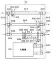
- FIG. 1 is a system configuration diagram of an automatic analysis system according to the first embodiment.
- the automatic analysis system 10 includes an inspection apparatus group 100, an apparatus management server 108, an inspection information management server 109, and an operation terminal 110.
- Each apparatus of the inspection apparatus group 100 and the apparatus management server 108 are communicably connected via an apparatus information network 111 such as a LAN (Local Area Network), and the apparatus management server 108, the inspection information management server 109, and the operation terminal 110 are connected.
- an inspection information network 112 such as a LAN.
- the examination information management server 109 is connected to another system in the hospital such as an electronic medical record system via the hospital network 113.
- the inspection apparatus group 100 includes a charging apparatus 101, a centrifuge apparatus 102, an opening apparatus 103, and a dispensing apparatus 104, which are pretreatment apparatuses, a linear conveyance apparatus 105, which is a conveyance apparatus, and a colorimetric analysis apparatus 106, which is an analysis apparatus. (A, B) and a storage device 107 which is a post-processing device, which are installed in an arrangement as shown in FIG. As will be described later, each of these apparatuses has a plurality of conveyance paths for carrying in and out of the specimen, and by connecting the conveyance paths of adjacent apparatuses, the specimens are connected between the apparatuses. Can be delivered. Note that the storage device 107 that collects the specimen is disposed at the left end so that the specimen insertion place and the processed specimen collection place are close to each other mainly in order to improve the workability of the laboratory technician.
- the specimen to be examined placed in a test tube or the like is introduced from an input apparatus 101 having two input ports for an emergency sample and a general sample.
- the urgent sample is sent to the centrifuge 102 in preference to the general sample.
- the urgent sample is sent to the centrifuge 102 in the order in which the general sample is introduced.
- the specimen carried into the centrifuge 102 is carried out to the next opening device 103 as it is when centrifugation is not necessary. If centrifugation is necessary, dozens of specimens are collected and centrifuged, and then the emergency specimen is preferentially carried out to the unplugging device 103 from the specimens for which centrifugation has been completed.
- the sample carried into the opening device 103 from the centrifuge 102 is unplugged in the order of loading, and then carried out to the dispensing device 104.
- a necessary number of child samples are generated by dispensing a predetermined amount corresponding to the type of examination from the loaded sample as a parent sample.
- the parent sample is transported in the reverse direction from the dispensing device 104 and collected or stored in the storage device 107, and the generated child sample is subjected to the colorimetric analyzer 106 (A, B) by the linear transport device 105. To be transported.
- the colorimetric analyzer 106 (A, B) a necessary test is performed using the loaded child sample, and the child sample for which the test has been completed is discarded.
- the pre-treatment device includes four injection devices 101, a centrifugal device 102, an opening device 103, and a dispensing device 104, each of which is a total of four, but there may be two or more of each.
- the transport device is only the linear transport device 105, there may be a device that changes the transport direction (such as an L-shaped transport device) or a buffer device that temporarily stores a sample. There may be more than one.
- the colorimetric analyzer 106 (A, B) can analyze a plurality of biochemical items with a single device. Therefore, a plurality of child samples dispensed from the same parent sample may be processed by one colorimetric analyzer 106 (A, B).
- the colorimetric analyzer 106 (A, B) is used as the analyzer, it may be an apparatus for analyzing other items such as electrolyte, immunity, and DNA, or an apparatus that can analyze a plurality of items at once. Further, one or more of these devices may be connected. Further, although the post-processing device is only the storage device 107, there may be a capping device or the like, and there may be one or more of each.
- the apparatus management server 108 and the inspection information management server 109 may be configured to include two or more units according to the processing load.
- Two or more operation terminals 110 may be provided according to the layout and operation of the examination room, or the operation terminals of the examination information management server 109 and the apparatus management server 108 may be substituted.
- each device is arranged as shown in FIG. 1, but the arrangement of the devices may be changed.
- FIG. 2 is an explanatory diagram of functions and operations of the automatic analysis system 10 according to the first embodiment. First, the functional configuration of the automatic analysis system 10 will be described with reference to FIG.
- Each device constituting the inspection device group 100 that is, a loading device 101, a centrifuge device 102, a plug opening device 103, a dispensing device 104, a linear conveyance device 105, a colorimetric analysis device 106 (A, B), and a storage device 107.
- Each includes a collection unit 201 and a mechanism control unit 202.
- the device management server 108 includes a tracking unit 203, a carry-in / out plan unit 204, a simulation unit 205, an instruction unit 206, a transport route DB (DataBase) 291, and a device model DB 292.
- the inspection information management server 109 includes an inspection information providing unit 207, an inspection request DB 293, and a parameter DB 294.
- the operation terminal 110 includes an operation management unit 208.
- the collection unit 201 of each device constituting the inspection device group 100 transmits the sensor value M271 indicating the detection state of the sample in each unit in the device to the tracking unit 203 of the device management server 108.
- the tracking unit 203 of the apparatus management server 108 uses the transport path specified by the inspection item of each specimen instructed to be carried in / out by the carry-in / out instruction M272 and the sensor value M271 of each apparatus, and the current position of each specimen. And the presence state (waiting area information D281) of the specimen for each waiting area where the specimen stays in each apparatus is calculated.
- the loading / unloading plan unit 204 of the apparatus management server 108 creates an initial loading / unloading plan D282 giving priority to the emergency sample based on the initial condition information M273 and the waiting area information D281.
- the simulation unit 205 of the apparatus management server 108 estimates the amount of waiting time in each waiting area (stagnation transition information D283 when a sample is loaded / unloaded according to the created loading / unloading plan D282). ) Is calculated by simulation based on the processing item information M274, the conveyance path information 291A, and the apparatus model information 292A.
- the carry-in / out plan unit 204 changes the carry-in / out timing and the order so that the calculated estimated amount of waiting time does not exceed the default value given by the initial condition information M273.
- the operation of performing the simulation again by correcting the above is repeated, and finally the carry-in / out plan D284 is created.
- the instruction unit 206 transmits a loading / unloading instruction M272 to the mechanism control unit 202 of the loading device 101 and the centrifuge device 102 according to the created loading / unloading plan D284.
- the automatic analysis system 10 can suppress the waiting time in each waiting area in the system to a predetermined value or less, and thereby can keep the TAT of the emergency sample within a predetermined time.
- FIG. 3 shows an example of the structure of the internal mechanism of the dispensing device 104 as a representative example.
- the transport mechanism provided in each device will be described in detail.
- the dispensing apparatus 104 illustrated in FIG. 3 includes a belt line 301 (A to E), a direction changing mechanism 302 (A to H), a stopper 303 (A to H), a specimen detection sensor 304 (A to I), and a process. It has a mechanism 305.
- the belt line 301 is a mechanism for transporting the sample in a fixed direction, and 301A and 301B transport the sample in the right direction in the figure and 301C in the left direction in the figure.
- the belt line 301B can be used, for example, to pass a sample that does not require a dispensing process, and the belt line 301C can be used to carry out a parent sample after the dispensing process.
- the direction changing mechanism 302 is a mechanism that changes the sample transport direction straight or 90 degrees left and right.
- the stopper 303 is a mechanism for temporarily stopping the sample.
- the specimen detection sensor 304 is a mechanism for detecting the presence or absence of a specimen or recognizing specimen identification information.
- the processing mechanism 305 is a mechanism for subdividing (dispensing) a specimen stopped in a region 310 indicated by a broken line on the belt line 301A.
- a feeder for supplying a tube or a cup, an XYZ table, a pipetter, a pump, Etc.
- the dispensing apparatus 104 generates a necessary number of child samples by the processing mechanism 305 using the sample carried in from the adjacent apparatus as a parent sample, and carries out both the parent sample and the subdivided child samples to the adjacent apparatus. At that time, by changing the distance between the stoppers 303, the number of samples to be stopped and the number of samples to be continuously carried out can be adjusted. Further, by synchronizing the operation timing of the stopper 303 between the apparatus to be carried out and the apparatus to be carried in, it is possible to prevent the collision of the specimen during the delivery of the specimen between the apparatuses.
- each line may be reduced or increased depending on the required performance of the apparatus.
- the robot arm may be used to carry the apparatus within and between apparatuses.
- the input device 101, the centrifuge device 102, the opening device 103, the colorimetric analyzer 106 (A, B), and the storage device 107 that perform other processes also have the same internal structure as the dispensing device 104 described above. Then, the processed sample is processed, and the processed sample is carried out to the next apparatus. Note that the linear transport device 105 does not have the processing mechanism 305 and transports the loaded sample to the next device.
- Dispensing device 104 is a device for processing the sample after it is carried into the device together with the container.
- the dispensing device 104 includes a device for directly sampling the contents of the sample (external sampling) from the linear transport device 105 or the like, and the linear transport device.
- a sampling region may be set by providing a stopper 303 and a sample detection sensor 304 in a part of the belt line 105.
- the loading apparatus 101 can carry in samples in an arbitrary order and timing using an XYZ table and a robot arm, and can recognize the identification information of the sample given to the sample or the tray. It is assumed that the centrifuge 102 can also carry out specimens in an arbitrary order and timing using an XYZ table and a robot arm.
- FIG. 4 is a diagram illustrating a hardware configuration example of each device of the inspection device group 100.
- Each device of the inspection device group 100 includes a CPU (Central Processing Unit) 401 that executes and executes a program, a ROM (Read Only Memory) 402 that stores a basic program such as an OS (Operating System), and processing data.
- CPU Central Processing Unit
- ROM Read Only Memory
- RAM Random Access Memory
- an external storage device 404 such as an HDD (Hard Disk Drive) or an external memory card
- a communication I / F Interface
- various sensors 406 including the sample detection sensor 304) used for processing and transporting the sample
- various actuators 408 including the stopper 303) used for processing and transporting the sample
- a controller for controlling the same 407, and can exchange data with each other via the CPU bus 409.
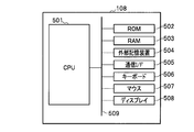
- FIG. 5 is a diagram illustrating a hardware configuration example of the device management server 108.
- the device management server 108 includes a CPU 501 that executes and executes programs, a ROM 502 that stores basic programs such as an OS, a RAM 503 that is used as a temporary storage area for processing data, an HDD, an external memory card, and the like.
- An external storage device 504, a communication I / F 505 connected to the device information network 111 and the inspection information network 112, a keyboard 506 and a mouse 507 as input devices, and a display 508 as an output device are configured. Can exchange data with each other.
- FIG. 6 is a diagram illustrating a hardware configuration example of the inspection information management server 109.
- the inspection information management server 109 includes a CPU 601 that executes and executes programs, a ROM 602 that stores basic programs such as an OS, a RAM 603 that is used as a temporary storage area for processing data, an HDD, an external memory card, and the like.
- External storage device 604 communication I / F 605 connected to examination information network 112 and hospital network 113, keyboard 606 and mouse 607 as input devices, and display 608 as an output device. Can exchange data with each other.
- FIG. 7 is a diagram illustrating a hardware configuration example of the operation terminal 110.
- the operation terminal 110 includes a CPU 701 for executing and calculating programs, a ROM 702 for storing basic programs such as an OS, a RAM 703 used as a temporary storage area for processing data, and an external device such as an HDD or an external memory card.
- a storage device 704, a communication I / F 705 connected to the inspection information network 112, a keyboard 706 and a mouse 707 as input devices, and a display 708 as an output device are configured to exchange data with each other via a CPU bus 709. You can communicate.
- the CPU 401 of each device executes a program stored in the ROM 402, the RAM 403, or the external storage device 404, and each hardware (communication I / F 405, This is realized by controlling the sensor 406, the controller 407, and the actuator 408).
- the tracking unit 203, the loading / unloading planning unit 204, the simulation unit 205, and the instruction unit 206 of the device management server 108 execute a program stored in the ROM 502, RAM 503, or external storage device 504, and each hardware (communication I / F505, keyboard 506, mouse 507, display 508).
- the CPU 601 executes a program stored in the ROM 602, the RAM 603, or the external storage device 604, and each hardware (communication I / F 605, keyboard 606, mouse 607, display 608). ).
- the CPU 701 executes a program stored in the ROM 702, RAM 703, or external storage device 704, and controls each hardware (communication I / F 705, keyboard 706, mouse 707, display 708). It is realized by doing.
- the collection unit 201 of each apparatus of the inspection apparatus group 100 transmits the sensor value M271 related to the position of the specimen from the sensor 406 to the tracking unit 203 of the apparatus management server 108.
- the mechanism control unit 202 of each apparatus in the inspection apparatus group 100 performs sample loading / unloading and sample processing based on the loading / unloading instruction M272 received from the instruction unit 206 of the apparatus management server 108.
- the tracking unit 203 of the apparatus management server 108 uses the sensor value M271 received from the collection unit 201 of each apparatus of the inspection apparatus group 100 and the conveyance path information 291A, and the retention state of the sample for each waiting area in each apparatus.
- the waiting area information D281 representing is calculated.
- the waiting area is an area where the specimen is processed or transported or the specimen is stopped or decelerated in order to wait for it.
- the area immediately before the stopper 303 can be a waiting area.
- the loading / unloading planning unit 204 of the apparatus management server 108 uses the waiting area information D281 and the initial condition information M273 received from the examination information providing unit 207 of the examination information management server 109 to give a loading / unloading plan that gives priority to emergency samples. D282 is created. Then, using the stagnation transition information D283 calculated by the simulation unit 205 described later, the carry-in / out plan D282 is corrected to create a final carry-in / out plan D284.
- the simulation unit 205 of the apparatus management server 108 uses the apparatus model information 292A, the waiting area information D281, the carry-in / out plan D282, and the processing item information M274 received from the inspection information providing unit 207 of the inspection information management server 109.
- the instruction unit 206 of the apparatus management server 108 transmits a loading / unloading instruction M272 to the loading device 101, the mechanism control unit 202 of the centrifuge 102, and the like based on the loading / unloading plan D284, and the order and timing of loading / unloading of samples. Instruct.
- the transport route DB 291 of the device management server 108 stores and manages the transport route information 291A.
- the device model DB 292 of the device management server 108 stores and manages device model information 292A.
- the inspection information providing unit 207 of the inspection information management server 109 generates initial condition information M273 and processing item information M274 from the request information 293A stored in the inspection request DB 293 and the plan parameter 294A stored in the parameter DB 294. , Respectively, to the carry-in / out planning unit 204 and the simulation unit 205 of the device management server 108.
- the examination request DB 293 of the examination information management server 109 stores and manages request information 293A registered by a doctor or an examination engineer using an electronic medical record system or the like.
- the parameter DB 294 of the examination information management server 109 stores and manages a plan parameter 294A registered by a doctor or an examination engineer.
- the operation management unit 208 of the operation terminal 110 performs input / output processing for registering the transport route information 291A, device model information 292A, request information 293A, and plan parameters 294A in various DBs, and displays the sample processing status.
- the transport route information 291A includes an item group definition table T100, a route definition table T200, and an item route correspondence table T300.
- the item group definition table T100 defines an item group, and has an item group ID (Identification) (T101) and a processing item ID (T102) as attributes.
- the item group ID (T101) is an identifier that defines an item group including a plurality of processing items to be performed on the specimen.
- the process item ID (T102) is an identifier of a process item to be performed on the sample. For example, when an item group including process items “biochemical process 1” and “biochemical process 3” is defined as an item group “biochemical general 1”, ⁇ biochemical general 1, biochemical process 1 ⁇ , ⁇ Two records of biochemical general 1, biochemical processing 3 ⁇ are registered.
- each apparatus of the test apparatus group 100 processes a sample based on an item group or a process item. For example, if a specimen of “Biochemistry General 1” requires a 5-minute centrifugation process, the centrifuge 102 performs a 5-minute centrifugation process based on the item group ID.
- the route definition table T200 defines a route for transporting the sample, and includes a route ID (T201), a transport order T202, a device ID (T203), and a branch point ID (T204). ) And branch direction T205 as attributes.
- the route ID (T201) is an identifier that defines a route for transporting the sample.
- the transport order T202 is a serial number representing the transport order in records having the same route ID, and indicates that transport is performed in ascending order of this number.
- the device ID (T203) is an identifier of a device to be transported.
- the branch point ID (T204) is an identifier representing a branch point inside the apparatus.
- the branch direction T205 represents in which direction the sheet should be conveyed at the branch point.
- route 1 when the route from the input device 101 to the dispensing device 104 in FIG. 1 is defined as “route 1”, ⁇ route 1, 1, input, branch point 4, above ⁇ , ⁇ path 1, 2, input , Branch point 5, right ⁇ , ⁇ path 1, 3, centrifuge, branch point 2, straight forward ⁇ , ⁇ path 1, 4, centrifuge, branch point 5, straight forward ⁇ , ⁇ path 1, 5, capping, branch point 2 , Straight ahead ⁇ , ⁇ path 1, 6, unplugged, branch point 5, straight forward ⁇ , ⁇ path 1, 7, dispensing, branch point 2, down ⁇ , and so on.
- the item route correspondence table T300 (FIG. 8C) represents the correspondence between the item group and the route, and the item group ID (T301), the post-dispensing ID (T302), the dispensing amount T303, It has a route ID (T304) as an attribute.
- T301 the item group ID
- T302 the post-dispensing ID
- T303 the dispensing amount
- T304 It has a route ID (T304) as an attribute.
- T304 a route ID
- T304 a route ID
- the device model information 292A is information used by the simulation unit 205 to execute a simulation, and includes a model object T400, a state definition table T500, a state transition table T600, and a connection definition table T900.
- the dispensing device 104 having the internal structure illustrated in FIG. 3 will be described as an example.
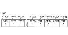
- the model object T400 (FIG. 9A) is a logical representation of the state of the device, and has a current state T401 and one or more queues (T402 ⁇ ) as attributes.
- Each queue is a collection (container) that has a one-to-one correspondence with each waiting area in the apparatus and holds the sample ID, which is the identifier of the sample, in the order in which the specimen is loaded into the corresponding waiting area.
- Each queue is provided with a queue ID that is a unique identifier throughout the automatic analysis system 10, and a capacity (queue size) corresponding to the hardware specifications of the apparatus is set in advance, and the number of samples that can be loaded is also retained. Is done. Therefore, the queue availability can be determined by appropriately storing the sample IDs of the samples existing in the respective waiting areas in the respective queues constituting the model object T400.
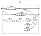
- FIG. 10 is a cue model representation in which a cue is associated with the hardware of the internal mechanism of the dispensing apparatus 104 illustrated in FIG.
- a cue is associated with the hardware of the internal mechanism of the dispensing apparatus 104 illustrated in FIG.
- the destination standby queue 1 T403
- queue size 5
- the model object T400 indicating the state of the dispensing apparatus 104 illustrated in FIG.
- FIG. 10 shows only the connection relationship of the queues in the dispensing device 104, but the connection relationship with the queues of adjacent devices is defined in the connection definition table T900 (FIG. 9D) described later. Is done.
- the current state T401 stores a state identifier (state ID) indicating which of the states defined by the state definition table T500 is the current state of the apparatus.
- state ID state identifier
- the state definition table T500 (FIG. 9B) defines the state of the apparatus according to the sample processing.
- state ID S3
- the parent work queue T406, the child work queue 1 (T407), and the child work queue 2 (T408) that affect the dispensing process are handled, and the return waiting queue T402 and the outgoing waiting queue that do not affect the dispensing process.
- 1 (T403), outgoing queue 2 (T404), and adjustment queue T405 are excluded from the attributes that define the state.
- the state transition table T600 (FIG. 9C) defines the state transition of the apparatus due to processing performed according to the sample processing item information M274 and the time required for processing.
- the state transition table T600 of the dispensing apparatus 104 has a transition source state T601, a transition destination state T602, a transition condition T603, and a processing time T604 as attributes.
- the processing time T504 is expressed as a constant value.
- an attribute representing a variation condition is added to set the processing time for each situation.
- the processing time may be expressed as a probability distribution such as a normal distribution.
- the connection definition table T900 (FIG. 9 (d)) represents the connection relationship between the devices in all the queues set by the model object T400 of each device and between the devices, and includes the transport source queue ID (T901) and , Device ID (T902), branch point ID (T903), branch direction T904, and transport destination queue ID (T905).
- T901 transport source queue ID
- T902 Device ID
- T903 branch point ID
- T904 transport destination queue ID
- T905 transport destination queue ID
- the queue IDs stored in the transport source queue ID (T901) and the transport destination queue ID (T905) are identifiers of queues included in the model object T400 of each device.
- the device ID (T902) and the branch point ID (T903) correspond to the device ID (T203) and the branch store ID (T204) in the route definition table T200 (see FIG. 8). Is associated.
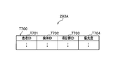
- the request information 293A includes an inspection request information table T700.
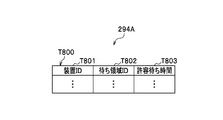
- the plan parameter 294A includes a plan parameter table T800.
- the plan parameter table T800 expresses an allowable waiting time in each waiting area in each device, and has a device ID (T801), a waiting area ID (T802), and an allowable waiting time T803 as attributes. .
- the automatic analysis system 10 creates a loading / unloading plan such that the waiting time in each waiting area of all samples including the emergency sample is equal to or less than the allowable waiting time T803, and controls loading / unloading. Therefore, by appropriately setting the allowable waiting time T803, the TAT of the emergency sample can always be within the target time.
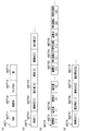
- the sensor value M271 (FIG. 13A) represents the detection contents of the specimen detection sensor 304 installed in each part of the apparatus of the inspection apparatus group 100.
- the detected time M2711, apparatus ID (M2712), sensor It consists of ID (M2713) and value M2714.
- the value M2714 is, for example, a binary value indicating whether or not the specimen is on the sensor, and is “1” if present and “0” if not present.
- the case where there is a sample the case where there is no sample but a carrier (holder or rack) for transporting, and the case where there is nothing may be distinguished.
- the loading / unloading instruction M272 (FIG. 13B) instructs the apparatus about the order and timing of loading / unloading of samples, and includes a loading / unloading time M2721, sample ID (M2722), and an instruction value indicating loading / unloading. It consists of multiple sets with M2723.
- the initial condition information M273 (FIG. 13C) represents the initial condition of the plan, and includes a plurality of sets of sample IDs (M2731) and priorities M2732, a device ID (M2733), and a waiting area ID ( M2734) and a plurality of sets of allowable waiting time M2735.
- the process item information M274 (FIG. 13D) represents a process item for each sample, and includes a plurality of sets of a sample ID (M2741) and an item group ID (M2742).
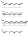
- the waiting area information D281 (FIG. 14A) is information indicating the staying state of the specimen in each waiting area in the apparatus of the test apparatus group 100 and the waiting order thereof, and includes the apparatus ID (D2811) and the waiting area ID ( D2812), waiting order (D2813), and specimen ID (D2814). Note that the waiting order is given sequential numbers of 1, 2, 3,.
- the carry-in / out plan D282 (FIG.
- the stagnation transition information D283 (FIG. 14 (c)) is information representing a temporal change in the waiting time of the specimen (may include processing to be added to the specimen) in each waiting area in the apparatus estimated by simulation.
- Time D2831 Time D2831, device ID (D2832), waiting area ID (D2833), sample ID (D2834), and waiting time D2835.
- the carry-in / out plan D284 (FIG. 14 (d)) represents the carry-in / out plan finally determined by the carry-in / out plan unit 204. From the apparatus ID (D2841), the time D2842, the sample ID (D2843), and the instruction value D2844. Become.
- the instruction value D2844 represents loading or unloading in the same manner as the instruction value M2723 of the loading / unloading instruction M272.
- each apparatus in this embodiment shall perform the process according to process item ID (T102) (refer FIG. 8) with respect to the carried-in sample, and shall carry out the processed sample.
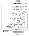
- the device management server 108 performs the following processing, for example, every second. In this embodiment, it is performed every second, but it may be set shorter or longer depending on the processing capability of the apparatus management server 108 or the like.
- the tracking unit 203 receives each waiting area (each queue of the model object T400) from the carry-in / out instruction M272, the sensor value M271 received from the collection unit 201 of each apparatus of the inspection apparatus group 100, and the conveyance path information 291A.
- the waiting state information D281 is calculated by calculating the staying state of the sample (step S101).
- the carry-in / out planning unit 204 calculates the state of each device according to the state definition table T500 (see FIG. 9), and initializes the model object T400 (step S102).
- the carry-in / out planning unit 204 issues a request to the inspection information providing unit 207 to acquire the initial condition information M273 (step S103).
- the inspection information providing unit 207 generates initial condition information M273 from the request information 293A and the plan parameter 294A in response to this request.
- the carry-in / out planning unit 204 detects a sample with a high priority T704 in the examination request information table T700 (see FIG. 11), a sample installed in the input tray or input port for an emergency sample, and suddenly A loading / unloading plan D282 for loading / unloading with the maximum processing performance while giving priority to the loaded emergency sample is created (step S104).
- the input apparatus 101 in this example has an apparatus ID of “input 1”, has three types of trays (emergency sample tray 3001A, general sample tray 3001B, and centrifuge path sample tray 3001C), and has a maximum of four from any tray. It is possible to carry in at the rate of one sample per second. At the current time 9:00: 00, as shown in FIG.
- the initial carry-in / out plan D282 created at this time includes contents such as a carry-in plan 3002 (FIG. 30B). That is, with regard to the order of loading, it is planned to first carry in the urgent sample in the order of arrival and then carry in the general sample in the order of arrival. With regard to the loading time, it is planned to carry in one sample every 4 seconds from the current time so as to carry in at the maximum processing speed of the loading device 101.
- the simulation unit 205 then issues a request to the examination information providing unit 207 to acquire the processing item information M274 (step S ⁇ b> 105).
- the inspection information providing unit 207 generates processing item information M274 from the request information 293A in response to this request.
- the simulation unit 205 calculates (simulates) the state transition up to 10 minutes later using the current state of each device, the processing item of each sample, the state transition table of each device, and the like, for example, 100 milliseconds.
- the stagnation transition information D283 in which the waiting time of each sample is estimated is calculated in units of (step S106).
- the state transition is calculated until 10 minutes later.
- the state transition may be set shorter or longer depending on the processing capability of the apparatus management server 108 and the like.
- the waiting time is estimated every 100 milliseconds, but it may be set shorter or longer.
- the simulation unit 205 determines whether the waiting time D2835 of all the samples in the stagnation transition information D283 is equal to or less than the allowable waiting time M2735 that is the default value set in the initial condition information M273 (step S107). . As a result, if the waiting time of all emergency samples is equal to or less than the predetermined value, the process proceeds to step S109 (Yes side), and if not, the process proceeds to step S108 (No side). If there is a sample whose waiting time exceeds the predetermined value (“No” in step S107), the loading / unloading planning unit 204 goes back and immediately before loading / unloading the sample exceeding the allowable waiting time.
- step S108 The new loading / unloading plan D282 whose time is delayed is corrected (step S108), and the processing from step S106 onward is performed again. A detailed description of the processing in step S108 will be given later.
- the carry-in / out plan unit 204 sets the contents of the current carry-in / out plan plan D282 as the final carry-in / out plan D284 and the instruction unit 206.
- the instruction unit 206 transmits a loading / unloading instruction M272 for instructing loading / unloading of each specimen to the mechanism control unit 202 of each corresponding apparatus of the test apparatus group 100, and the process is terminated (step S109).
- the mechanism control unit 202 instructed to load and unload each sample performs mechanism control for loading and unloading the sample in accordance with the instruction.
- step S101 in FIG. 15 the process of calculating the waiting area for each specimen (step S101 in FIG. 15) will be described in detail with reference to FIG.
- This process is executed asynchronously for each waiting area.
- the tracking unit 203 performs the processing from step S202 onward for each sample as long as there is a sample for which the waiting area has not been calculated. If all the samples being processed have already calculated the waiting area, this processing ends.
- Step S201 When there is a sample whose waiting area has not been calculated, the tracking unit 203 acquires the transport route of the sample from the transport route information 291A (FIG. 8) (step S202).
- step S203 acquires the latest sensor value that matches the sample from the received sensor value M271 (step S203).
- the tracking unit 203 determines the waiting area and the waiting order of the sample using the latest acquired sensor value, and adds the record to the waiting area information D281 and registers it (step S204).
- the waiting area to be determined is (1) when the specimen is stopped by the stopper 303 or the like and is in the detection state, the waiting area corresponding to the installation location of the specimen detection sensor 304 to which the latest sensor value is given (2 )
- the determination is made in the waiting area where the sample detection sensor 304 to which the latest sensor value is applied is reached next in the transport path acquired from the transport path information 291A.
- step S106 in FIG. 15 the stagnation transition information calculation process (step S106 in FIG. 15) will be described in detail with reference to FIG. This process is executed in parallel for each model object.
- the simulation unit 205 sets the simulation time to the current time, and sets the current state of the apparatus to the model object T400 (see FIG. 9) (step S301). Specifically, the state of the apparatus calculated in step S102 of FIG. 15 is set to the current state T401 of the model object T400, and the waiting state of each specimen acquired from the waiting area information D281 (see FIG. 14) is set as the model object T400. Set for each queue. Further, a record indicating the waiting time of each sample at the present time is added to the stagnation transition information D283 and registered.
- the waiting time of each sample at the present time is calculated as a difference between the current time and the loading time detected by the sample detection sensor 304.
- the simulation unit 205 refers to the processing item information M274 of each sample acquired in step S105 in FIG. 15, and among the state transitions defined in the state transition table T600, satisfies the transition condition at the earliest time. One is selected (step S302).
- the simulation unit 205 proceeds to step S304 unless the simulation time has passed the completion time (10 minutes after the current time), and ends this processing if the completion time has passed (step S303). ⁇ End).
- the simulation unit 205 refers to the state transition table T600 to determine whether or not the time necessary for the state transition satisfying the transition condition has elapsed (step S304). As a result, if the time necessary for the state transition has elapsed, the process proceeds to step S305 (Yes side), and if not, the process proceeds to step S309 (No side).
- step S304 determines whether there is a sample to be carried out in the next waiting area as a result of the state transition (step S304). S305). As a result, if there is a sample to be carried out, the process proceeds to step S306 (Yes side), and if not, the process proceeds to step S308 (No side).
- step S305 When there is a sample to be carried out (“Yes” in step S305), the simulation unit 205 refers to the model object T400 of the apparatus including the carry-out destination queue and determines whether or not there is an empty in the carry-out destination queue (step). S306). As a result, if there is a vacancy in the carry-out destination queue, the process proceeds to step S307 (Yes side), and if not, the process proceeds to step S309 (No side).
- the simulation unit 205 carries out the sample to the delivery destination queue (step S307). Specifically, the time taken to carry out the reservation for carrying out the sample to be carried out to the queue of the carry-out destination that is executing the simulation in parallel and acquired from the corresponding processing time T604 in the state transition table T600. Only after waiting, the data corresponding to the sample is deleted from the queue of the export source, and the waiting time D2835 of the record of the stagnation transition information D283 corresponding to each sample remaining in the queue of the export source is applied to the export. Time is added and the time D2831 is updated.
- the sample loading reservation is used as input data when the simulation of another apparatus is executed, and other items that are loaded at a time earlier than the sample when the empty destination queue is determined in step S306. This is used to determine whether or not there is no empty space in the destination queue depending on the sample.
- step S307 ends or when there is no sample to be carried out (“No” in step S305)
- the simulation unit 205 corresponds the current state T401 of the model object T400 to the state after the transition according to the state transition table T600.
- the apparatus state of the apparatus is updated (step S308), and then the process returns to step S302 to repeat the above process.
- step S304 When the time required for the state transition has not elapsed (“No” in step S304), or when there is no empty in the export destination queue (“No” in step S306), the simulation unit 205 sets the simulation time to 100. After incrementing the time so as to advance by milliseconds (step S309), the process returns to step S303 and the above process is repeated.
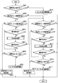
- step S108 in FIG. 15 the correction process (step S108 in FIG. 15) of the carry-in / out plan D282 will be described in detail with reference to FIG.
- the carry-in / out planning unit 204 detects samples whose waiting time D2835 registered in the stagnation transition information D283 as a result of the simulation exceeds the predetermined value (allowable waiting time M2735) of the waiting area at the earliest time (first). Extract (step S401).
- the time exceeding the predetermined value of the unloaded sample is calculated by subtracting the difference between the waiting time D2835 and the allowable waiting time M2735 from the time D2831, and the time exceeding the default value of the unexported sample is Calculation is performed by adding the time obtained by subtracting the allowable waiting time M2735 from the difference between the last simulation time and the time D2821 to the time D2831 of the record related to the last export registered in the stagnation transition information D283.
- the carry-in / out planning unit 204 determines whether or not the target specimen needs to be centrifuged (step S402). As a result, if it is not necessary to perform the centrifugal process, the process proceeds to step S403 (Yes side), and if not, the process proceeds to step S404 (No side).
- the carry-in / out plan unit 204 adjusts the carry-out time from the centrifuge 102 (step S403). Specifically, in the vicinity of the time when the target sample is transported through the centrifuge device 102, the transport time of other general samples that use the same transport path as the target sample from the centrifuge device 102 is delayed by 2 seconds.
- the plan D282 is corrected.
- the carry-in / out plan unit 204 adjusts the carry-in time from the loading device 101 (step S404). Specifically, the loading / unloading plan D282 is corrected so that the loading time from the loading device 101 is delayed by 2 seconds from the sample two samples before the target sample.
- the process of adjusting the carry-out time from the centrifuge 102 (step S403) is performed, for example, by processing a plurality of general specimens with a certain centrifuge, and after the general specimens are processed, they are transported all at once and beyond.
- the waiting time of an emergency sample that does not require centrifugation after that exceeds the default value the removal of the general sample from the centrifuge device is suppressed, This is a process for processing an urgent sample first.
- step S404 a description will be given of a modification example of the carry-in plan in the process of adjusting the carry-in time from the input device 101 (step S404).
- the waiting time of the sample S9 which is a general sample that requires centrifugal processing, as a result of simulation when it is loaded from the loading device “loading 1” based on the initial loading plan 3101 (FIG. 31A)
- the allowable waiting time is exceeded in the opening device 103.
- the loading time is delayed from the sample two samples before the sample S9.
- the first correction is implemented.
- the loading times of the specimens S7, S8, and S9 are each delayed by 2 seconds (corrected first loading plan 3102 (FIG. 31 (b))). Even if the carry-in / out plan is corrected as described above, the second correction is performed when the waiting time of the sample S9 again exceeds the allowable waiting time. As a result, the specimens S7, S8, and S9 are introduced with a delay of 4 seconds from the original schedule (second modified delivery plan 3103 (FIG. 31 (c))). As a result of correcting the loading plan as described above, if the waiting time in all waiting areas of all the samples does not exceed the allowable waiting time, the correction of the loading / unloading plan D282 is completed. At this time, in the second and subsequent corrections, the number of samples that delay the carry-in time may be sequentially increased.
- the carry-out time or the carry-in time is delayed by 2 seconds for each correction, but it may be less or more depending on the processing performance of the device management server 108. . Moreover, although the carry-in time is delayed from two samples before, it may be less or more than that. Further, when the carry-out time from the centrifuge 102 is adjusted, the carry-in time from the input device 101 may not be adjusted.
- the processing method is a heuristic method, but in addition to this, an operation for changing the order of loading and unloading and the time may be defined as an operator, and an optimization method such as a Monte Carlo method may be used in combination.
- the correction related to one sample whose waiting time exceeds the specified value is performed at the earliest time.
- correction related to a plurality of samples whose waiting time exceeds the specified value is performed collectively. May be.
- the plan is corrected by performing a simulation up to 10 minutes after 100 milliseconds.
- the plan is detected by detecting the occurrence of traffic jams from the number of specimens in the waiting area and their positions. It is good also as what corrects.
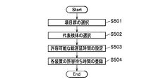
- FIG. 19 is a flowchart showing an example of the registration process of the plan parameter table T800
- FIG. 20 is a display example of a plan parameter registration screen used for the registration process of the plan parameter table T800.
- This plan parameter registration screen is input / output controlled by the operation management unit 208 of the operation terminal 110.
- a registrant such as an inspection engineer uses the item group combo box G101 to select one arbitrary item group from among previously registered item groups (step S501).
- the transport route of the sample corresponding to the selected item group is displayed in a graph on the flow view G102.
- the registrant confirms the transport route displayed on the flow view G102 and displays the representative sample combo.
- a representative sample whose parameters are to be registered is selected from the transported samples (parent sample and dispensed child samples) (step S502).
- the shortest processing time box G104 the predicted TAT time when processing is performed in the shortest time is displayed.
- the allowable delay time combo box G105 is used to set a maximum allowable delay time when the selected representative sample is an emergency sample (step S503).
- the operation management unit 208 waits in each waiting area that occurs when each device operates at its maximum processing capacity without waiting.
- the sum of the time (T1) and the value (T2) obtained by dividing the set maximum delay time by the number of waiting areas through which the specimen passes is set as the allowable waiting time T803 of each waiting area in the plan parameter table T800. Is registered (step S504). The registration can be canceled by pressing the Cancel button G107.
- the waiting time in each waiting area of all the samples of the emergency sample and the general sample can be suppressed to a predetermined value or less.
- TAT can always be within the target time.
- FIG. 21 is a system configuration diagram of the automatic analysis system according to the second embodiment.
- the automatic analysis system 20 includes an inspection apparatus group 2100, an apparatus management server 2115, an inspection information management server 2116, and an operation terminal 2117.
- Each device of the inspection device group 2100 and the device management server 2115 are communicably connected via a device information network 2118 such as a LAN, and the device management server 2115, the inspection information management server 2116, and the operation terminal 2117 are similarly connected to the LAN. Or the like via a test information network 2119.
- the examination information management server 2116 is connected to another system in the hospital such as an electronic medical record system via the hospital network 2120.
- the inspection device group 2100 includes a capping device 2101, a storage device 2102, a loading device 2103, a centrifuge device 2104, a capping device 2105, a dispensing device 2106, linear conveying devices 2107 and 2111, and a direction changing device 2108. , 2112, buffer devices 2109 and 2113 that can change the sample delivery order, a colorimetric analyzer 2110 (A, B), and an immune analyzer 2114 (A, B), as shown in FIG. It is installed with proper arrangement.
- FIG. 22 is an explanatory diagram of functions and operations of the automatic analysis system 20 according to the second embodiment. First, the functional configuration of the automatic analysis system 20 will be described with reference to FIG.
- Each device constituting the inspection device group 2100 includes a collection unit 201 and a mechanism control unit 202, respectively.
- the device management server 2115 includes a tracking unit 203, a carry-in / out plan unit 204, a simulation unit 205, an instruction unit 206, a transport route DB 291 and a device model DB 292.
- the inspection information management server 2116 includes an inspection information providing unit 207, an inspection request DB 293, and a parameter DB 294.
- the operation terminal 2117 includes an operation management unit 208.
- the collection unit 201 of each apparatus constituting the inspection apparatus group 2100 transmits the sensor value M271 indicating the detection state of the sample in each part in the apparatus to the tracking unit 203 of the apparatus management server 2115.
- the tracking unit 203 of the device management server 2115 uses the transport path specified by the test item of each sample instructed to be carried in / out by the carry-in / out instruction M272 and the sensor value M271 of each device, and the current position of each sample. And the existence state (waiting area information D281) of the specimen for each area where the specimen stays in each apparatus is calculated.
- the loading / unloading plan unit 204 of the apparatus management server 2115 creates an initial loading / unloading plan D282 giving priority to the emergency sample based on the initial condition information M273 and the waiting area information D281.
- the simulation unit 205 of the device management server 2115 estimates the waiting time in each waiting area (stagnation transition information D283 when a sample is loaded / unloaded according to the created loading / unloading plan D282). ) Is calculated by simulation based on the processing item information M274, the conveyance path information 291A, and the apparatus model information 292B.
- the carry-in / out plan unit 204 changes the carry-in / out timing and the order so that the calculated estimated amount of waiting time does not exceed the default value given by the initial condition information M273.
- the operation of performing the simulation again by correcting the above is repeated, and finally the carry-in / out plan D284 is created.
- the instruction unit 206 transmits a loading / unloading instruction M272 to the mechanism control unit 202 of the loading device 2103, the centrifuge device 2104, and the buffer devices 2109 and 2113 according to the created loading / unloading plan D284.
- the automatic analysis system 20 can suppress the waiting time in each waiting area in the system to a predetermined value or less, thereby keeping the TAT of the emergency sample within a predetermined time.
- the structure of the internal mechanism of the other devices except the direction changing devices 2108 and 2112 is the same as that described in the first embodiment.
- the input device 2103 can carry in samples in an arbitrary order and timing using an XYZ table and a robot arm, and can recognize the identification information of the sample given to the sample or the tray. It is assumed that the centrifuge 2104 and the buffer devices 2109 and 2113 can also carry out specimens in any order and timing using the XYZ table and the robot arm.
- FIG. 23 shows an example of the structure of the internal mechanism of the direction changing device 2108.
- the transport mechanism of the direction changing devices 2108 and 2112 will be described in detail with reference to FIG.
- the direction changing device 2108 illustrated in FIG. The functions of these mechanisms are the same as those described in the first embodiment.
- an area such as the direction changing mechanism 2302 that needs to be exclusively controlled is referred to as a shared unit.
- the direction changing device 2108 transports the sample from one queue to another in units of control cycles (for example, 1 second), whereas other devices asynchronously control the transport of the sample in units of stoppers.
- a plurality of queues are processed at the same time unless the same sharing unit is used. That is, in FIG. 24 in which the structure of the internal mechanism shown in FIG. 23 is expressed as a queue model, for example, the transfer from the queue 4 to the queue 12 and the transfer from the queue 6 to the queue 10 can be carried in the same control cycle.
- the transport from the queue 4 to the queue 12 and the transport from the queue 8 to the queue 5 cannot be transported in the same control cycle because the upper left shared portion in the figure is used for either transport.
- the characteristics of the processing performance of the direction changing mechanism 2302 will be described.
- the sample heading from queue 1 to queue 10 and the sample heading from queue 3 to queue 12 are transported continuously in the same time zone, only different shared parts pass through, so the maximum performance is achieved for samples transported from either one. Can be transported by.
- the sample heading from queue 1 to queue 10 and the sample heading from queue 3 to queue 9 are transported in the same time zone, the sample heading from queue 1 to queue 6 and the sample heading from queue 5 to queue 9
- the same shared part at the lower left in the figure is used. For example, if control is performed so that the queue 5 is always given priority over the queue 1 and there are samples in the queue 5, the samples are transferred from the queue 5 to the queue 9 until there are no more samples in the queue 5.
- the direction changing device 2108 has a lower conveyance performance when the sample uses the same sharing unit than when the sample does not use the same sharing unit.
- the hardware configuration of each device of the inspection device group 2100 is the same as the hardware configuration of each device of the inspection device group 100 described in the first embodiment.
- the hardware configuration of the device management server 2115 is the same as the hardware configuration of the device management server 108 described in the first embodiment.
- the hardware configuration of the inspection information management server 2116 is the same as the hardware configuration of the inspection information management server 109 described in the first embodiment.
- the hardware configuration of the operation terminal 2117 is the same as the hardware configuration of the operation terminal 110 described in the first embodiment.
- the information structure of the automatic analysis system 20 is the same as that of the first embodiment except that the device model information 292A is the device model information 292B. Therefore, only the device model information 292B of the automatic analysis system 20 will be described in detail with reference to FIGS. 9, 23, 24, and 25.
- FIG. 9 The information structure of the automatic analysis system 20 is the same as that of the first embodiment except that the device model information 292A is the device model information 292B. Therefore, only the device model information 292B of the automatic analysis system 20 will be described in detail with reference to FIGS. 9, 23, 24, and 25.
- the device model information 292B is information used by the simulation unit 205 to execute the simulation.
- the model object T400, the state definition table T500, the state transition table T600, and the connection definition table T900 are the same as those described in the first embodiment.
- the carry-in / out plan D284 (FIG. 14) has the same structure as the first embodiment.
- the instruction value D2844 for the direction changing devices 2108 and 2112 is not a value representing carry-in or carry-out, but a value representing which direction is preferentially carried in.
- the state definition table T1000 for the direction changing device illustrated in FIG. 25 defines the state of the direction changing device 2108.
- the sharing unit represents a usage state of an area that needs to be exclusively controlled, such as the direction changing mechanism 2302 (A to D) in FIG.
- the direction changing device 2108 gives the usage status to the state definition table in order to define the exclusive control operation as described above. That is, a more accurate simulation can be performed by setting the transport direction and transport time of the specimen for each state defined and distinguished in the state definition table T1000 for the direction changing device.
- each apparatus in this embodiment shall perform the process according to process item ID (T102) (refer FIG. 8) with respect to the carried-in sample, and shall carry out the processed sample.
- process item ID T102
- the basic flow of processing in the second embodiment is the same as that of the first embodiment, except that the state definition table T500 and the state definition table T1000 for the direction changing device are used together, and the loading / unloading plan revision process. This is the same as the process flow.
- the loading / unloading planning unit 204 extracts a sample whose waiting time D2835 registered in the stagnation transition information D283 as a result of the simulation exceeds the predetermined value (allowable waiting time M2735) of the waiting area at the earliest time (Ste S601).
- the method for calculating the time exceeding the predetermined value is the same as that in step S401 (FIG. 18).
- the carry-in / out planning unit 204 refers to the stagnation transition information D283 to wait for the target sample around the direction change devices 2108 and 2112 and to pass through the same waiting area a plurality of times. It is determined whether there are many return operations (step S602). As a result, if waiting has occurred around the direction change devices 2108 and 2112 and there are many return operations, the process proceeds to step S603 (Yes side), and if not, the process proceeds to step S605 (No side). To proceed.
- the carry-in / out plan unit 204 adjusts the carry-out time from the buffer devices 2109 and 2113. This is performed (step S603). Specifically, the loading / unloading plan D282 is modified so that the unloading time of the general sample in the buffer devices 2109 and 2113 is delayed by 2 seconds around the time when the target sample is unloaded from the buffer devices 2109 and 2113.
- the case where there are many return operations means a case where 30% or more of the samples carried into the direction changing devices 2108 and 2112 perform the return operation. In this embodiment, it is 30%, but it may be increased or decreased depending on the system configuration and operation.
- the carry-in / out planning unit 204 performs priority control of the direction changing devices 2108 and 2112 (step S604). Specifically, in the devices adjacent to each direction (for example, for the direction changing device 2108, the linear transport device 2107, the linear transport device 2111, and the buffer device 2109), the sample is most congested (the waiting time of the sample). The direction changing devices 2108 and 2112 are controlled so that the sample from the waiting area is transported with priority. In this embodiment, adjacent devices are subject to priority control. However, instead of the linear transport device 2107 and the linear transport device 2111 that are not directly involved in the sample traffic jam, the dispensing device 2106 and the buffer device 2113 are targeted. It is good.
- step S605 determines that the target sample is It is determined whether or not it is not necessary to centrifuge. As a result, if it is not necessary to perform the centrifugal process, the process proceeds to step S606 (Yes side); otherwise, the process proceeds to step S607 (No side).
- step S606 Yes side
- step S607 No side
- the carry-in / out planning unit 204 adjusts the carry-out time from the centrifuge 2104 (step S606).
- the transport time of other general specimens that use the same transport path as that of the target specimen from the centrifuge 2104 is delayed by 2 seconds.
- the plan D282 is corrected.
- the carry-in / out plan unit 204 adjusts the carry-in time from the loading device 2103 (step S607).
- the loading / unloading plan D282 is corrected so that the loading time is delayed by 2 seconds from the sample two samples before the target sample.
- the process for adjusting the carry-out time of the buffer device (step S603) and the priority control process for the direction changing device (step S604) are, for example, processing a general sample by a certain analyzer and processing the general sample.
- a competition occurs and traffic jam occurs around the direction changer.
- This is a process for operating the system with high efficiency while guaranteeing TAT by suppressing the removal of the specimen from the analyzer and processing the emergency specimen first when the waiting time exceeds a predetermined value. .
- a set of unloading source queues that can unload samples to each queue (for example, queues 9, 10, 11, and 12 in FIG. 24) corresponding to the unloading port of the direction changing device in one process. It is defined as “Block”.
- Block In the example of FIG. 24, block 1 is queue 1 and queue 5, block 2 is queue 2 and queue 6, block 3 is queue 3 and queue 7, block 4 is queue 4 and queue 8, and so on.
- Block In the example of FIG. 24, block 1 is queue 1 and queue 5, block 2 is queue 2 and queue 6, block 3 is queue 3 and queue 7, block 4 is queue 4 and queue 8, and so on.
- Step S701 the direction including the sample that will be the maximum waiting time in the future (maximum waiting direction) and the waiting time (maximum waiting time) are calculated ( Step S701).
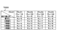
- the priority order of the queue is set based on the priority queue determination rule table (T2000) illustrated in FIG. 28 (step S702). Specifically, if the above-mentioned maximum waiting time does not exceed a predetermined value for each waiting area, “no priority” is set, and in block 1, the queue 5 is given priority over the queue 1, and in block 2, the queue 2 is queued.
- the priority is set so that the queue 6 is transported with priority, the queue 7 is transported with priority over the queue 3 in the block 3, and the queue 8 is transported with priority over the queue 4 in the block 4.
- the loading direction giving priority to the maximum waiting direction is set. For example, when the priority loading direction is “right priority”, the queue 5 is transported with priority over the queue 1 in the block 1, and the queue 6 is transported with priority over the queue 2 in the block 2.
- the priority order is set so that the queue 3 is transported with priority over the queue 7 in 3, and the queue 8 is transported with priority over the queue 4 in the block 4.
- a transport control plan for each queue is made by calling the processing (step S703).
- a queue that is determined to be given priority is referred to as a high priority queue, and a queue that is not so is referred to as a low priority queue.
- the SolveBlock process determines the sample to be transported in each block while calling itself recursively. First, it is determined whether the number of recursive calls for SolveBlock processing is not the fourth (step S801). As a result, if the number of recursive calls is not the fourth, the process proceeds to step S802 (Yes side), otherwise (“No” in step S801), the process proceeds to step S818 (No side). If the number of recursive calls is not the fourth (“Yes” in step S801), it is determined whether there is an unconveyed sample in the high priority queue (step S802). As a result, if there is an unconveyed sample, the process proceeds to step S803 (Yes side), and if not, the process proceeds to step S810 (No side).
- step S803 If there is an unconveyed sample in the high priority queue (“Yes” in step S802), the destination is any one of the queues 9, 10, 11, and 12 and the sample can be transported (there is an empty space and Whether the shared unit is not used) is determined (step S803). As a result, if the destination is any one of the queues 9, 10, 11, and 12 and the sample can be transported, the process proceeds to step S804 (Yes side). Otherwise, the process proceeds to step S805 (No side). If the destination is any one of the queues 9, 10, 11, and 12 and the sample can be transported (“Yes” in step S803), the sample is transported from the queue with a high priority, and the process is terminated ( Step S804).
- step S803 If the destination is not any of the queues 9, 10, 11, and 12 or the sample cannot be transported ("No" in step S803), it is determined whether or not the sample can be transported to the destination queue (step S805). . As a result, if the conveyance is possible, the process proceeds to step S808 (Yes side), and if not, the process proceeds to step S806 (No side). If the transfer is not possible (“No” in step S805), the SolveBlock process is called with the identifier of the block to which the destination queue belongs (step S806). Next, it is determined again whether the sample can be transported (step S807). As a result, if it can be transported, the process proceeds to step S808 (Yes side), and if not, the process proceeds to step S810 (No side).
- step S808 If it can be transported in step S805 or step S807 (“Yes” in step S805, “Yes” in step S807), it is determined whether it is the first recursive call (step S808). As a result, if it is the first recursive call (“Yes” in step S808), the process proceeds to step S804 (Yes side), and if not, the process proceeds to step S809 (No side). If it is not the first recursive call (“No” in step S808), the sample is transported from one of the queues 5, 6, 7, and 8, and the process ends (step S809).
- step S810 If there is no untransported sample in the high priority queue in step S802 (“No” in step S802), or if the sample cannot be transported in step S807 (“No” in step S807), the queue with low priority It is determined whether or not there is an untransported sample (step S810). As a result, if there is an unconveyed sample in the low priority queue, the process proceeds to step S811 (Yes side), and if not (No side), the process ends. If there is an untransported sample in the low priority queue (“Yes” in step S810), it is determined whether the destination of the sample is any one of the queues 9, 10, 11, and 12 and the sample can be transported. It is determined (step S811). As a result, if the destination is any one of the queues 9, 10, 11, and 12 and the sample can be transported, the process proceeds to step S812 (Yes side), and if not, the process proceeds to step S813 (No side). To proceed.
- step S811 If the destination is any one of the queues 9, 10, 11, and 12 and the sample can be transported (“Yes” in step S811), the sample is transported in the queue with the low priority, and the processing is terminated ( Step S812). If the destination is not any of the queues 9, 10, 11, and 12 or the sample cannot be transported ("No" in step S811), it is determined whether or not the sample can be transported (step S813). As a result, if the conveyance is possible, the process proceeds to step S816 (Yes side), and if not, the process proceeds to step S814 (No side).
- step S813 If the transfer is not possible (“No” in step S813), the SolveBlock process is called with the identifier of the block to which the destination queue belongs (step S814). Next, it is determined again whether the sample can be transported (step S815). As a result, if the conveyance is possible, the process proceeds to step S816 (Yes side), and if not (“No” in step S815), the process ends.
- step S816 If it can be transported in step S813 or step S815 (“Yes” in step S813, “Yes” in step S815), it is determined whether it is the first recursive call (step S816). As a result, if it is the first recursive call, the process proceeds to step S812 (Yes side), and if not, the process proceeds to step S817 (No side). If it is not the first recursive call (“No” in step S816), the sample is transported from any one of the queues 5, 6, 7, and 8, and the process ends (step S817).
- the carry-in / out planning unit 204 can determine from which queue to which sample the sample is to be transported.
- the direction changing device 2108 illustrated in FIG. 23 is planar, but the same applies to a structure in which a direction changing mechanism is connected in three dimensions.
- the direction change device in which the four direction change mechanisms shown in the present embodiment are arranged may be considered as one surface, and the same device may be arranged in two vertical directions and connected to each other. . Even if the mechanism (turntable) is not a direction changing device in the present embodiment but can rotate while the sample is placed on the center, it is shared on the hardware when the sample is transported continuously in the same time zone.
- the processing performance derived from the part changes.
- the priority control at that time simply receives the sample equally in the left, right, up and down directions when priority is not given to any direction, and receives the sample with high frequency from the desired direction when giving priority to any direction. It is feasible.
- the adjustment method of carry-in / out is as follows: (1) adjustment of carry-in time from the input device, (2) adjustment of carry-out time from the centrifugal device, (3) adjustment of carry-out time from the buffer device, (4) Although priority control processing in the direction changing device is performed, only one of these may be performed, any two or more may be combined, or combined with other adjustment methods May be. Moreover, you may limit the target apparatus which adjusts carrying in / out.
- the present invention when the initial loading / unloading plan draft created by the loading / unloading planning unit is applied from the presence state of the sample in the automatic analysis system and the operation model of the automatic analysis system.
- the waiting time in each waiting area is simulated, and when the waiting time exceeds the allowable value, the TAT of the emergency sample is set to a certain time by suppressing the loading / unloading of the sample or changing the loading / unloading sequence. Can fit within.
- the TAT of the emergency specimen is guaranteed, so that the examination engineer can throw in the specimen without worrying about the order and timing of specimen loading.
- the efficiency of the entire examination can be improved.
Landscapes
- Business, Economics & Management (AREA)
- Human Resources & Organizations (AREA)
- Engineering & Computer Science (AREA)
- General Physics & Mathematics (AREA)
- Health & Medical Sciences (AREA)
- Physics & Mathematics (AREA)
- General Health & Medical Sciences (AREA)
- Economics (AREA)
- Strategic Management (AREA)
- Entrepreneurship & Innovation (AREA)
- Pathology (AREA)
- Biochemistry (AREA)
- Analytical Chemistry (AREA)
- Chemical & Material Sciences (AREA)
- Immunology (AREA)
- Life Sciences & Earth Sciences (AREA)
- Tourism & Hospitality (AREA)
- General Business, Economics & Management (AREA)
- Theoretical Computer Science (AREA)
- Marketing (AREA)
- Quality & Reliability (AREA)
- Game Theory and Decision Science (AREA)
- Educational Administration (AREA)
- Development Economics (AREA)
- Operations Research (AREA)
- Primary Health Care (AREA)
- Epidemiology (AREA)
- Medical Informatics (AREA)
- Public Health (AREA)
- Automatic Analysis And Handling Materials Therefor (AREA)
- Child & Adolescent Psychology (AREA)
Abstract
自動分析システム内における検体の停滞状況を正確に予測し、各装置における検体の搬入出のタイミングと搬入出の順序とを調節することにより、緊急検体のTATの増加を防ぐ。 前記各装置における検体の搬入出を指示する装置管理サーバは、センサの信号を用いて投入済みの検体の現在位置を特定するトラッキング部と、各検体の現在位置を初期状態として、与えられた搬入出計画案を適用したときの各装置の動作をシミュレートすることにより、各検体の各部における滞留時間を推定するシミュレーション部と、緊急検体を優先的に搬入出する初期の搬入出計画案を作成して、シミュレーション部にシミュレーションを実行させ、その搬入出計画案を適用したときの各部における滞留時間が、当該各部の許容滞留時間を超えないように他の検体の搬入出のタイミングまたは搬入出の順序を修正する搬入出計画部とを備える。
Description
本発明は、臨床検査における自動分析システムに関し、特に、緊急性の高い検体を定められた時間内に検査するための技術に関する。
患者の血液や尿といった検体の検査業務では作業の迅速化が求められる。特に、診察前検査の検体や急患の検体といった緊急性の高い検体(緊急検体)については、検体が検査室に到着してから検査結果を出すまでのTAT(Turn Around Time)は20分~30分が目標となっている。
検体の検査業務を自動化する自動分析システムは、遠心、開栓、分注といった前処理を行う装置群、検査項目に応じた分析を行う分析装置群、分類、収納、廃棄といった後処理を行う装置群、それらの装置間を接続する搬送路を形成する搬送装置、装置群を管理するサーバ、検査情報を管理するサーバ、検査業務を担当する検査技師が検査依頼、検査結果の管理、装置群の設定を行う操作端末などから構成されており、投入された多様な検体を検査依頼に応じて自動的に検査する。また、一般的な自動分析システムでは、検体が投入される投入装置に優先度の異なる複数の投入口を設け、優先度の高い投入口に投入された緊急検体を一般検体より優先して処理することができるようになっている。
ところが、週明けの午前中など多くの検査依頼が発行される時間帯では、一部の装置の処理能力不足によって装置内や搬送路上に多数の検体が停滞してしまう渋滞現象が発生し、緊急検体を含む検体全体のTATが大幅に増加するという問題があった。この問題に対して、例えば特許文献1には、センサを使って、搬送路上および各装置のバッファ内の検体の存在状況を監視し、搬送路上に検体が停滞しないように検体の投入を抑制する技術が開示されている。
しかしながら、特許文献1の技術だけでは、搬送路の下流における検体間の干渉までは予測できないので、例えば、通常よりも分注比の高い検体があったり、複数の装置を経由する必要がある検体が投入されたりすると、分注装置の前後や搬送路の分岐点や合流点に設置される方向転換装置の付近に渋滞が生じることがあった。
また、一般的な自動分析システムの構成においては、分注装置や分析装置は、数十検体をまとめて処理する遠心装置の下流に接続されるので、検体の追い越しがない場合、1回の遠心処理のために投入された数十検体の後に投入された検体は、その前に投入された数十検体の処理が終わるまで待たされることになる。したがって、緊急検体であっても、投入のタイミングによっては、1回の遠心処理に要する数分の単位でTATが増加してしまうことがあった。
一方、検体の追い越しが可能な搬送ラインがあったり、渋滞が生じている経路とは別の経路で検体を搬送できたりする場合には、システムの一部に渋滞が発生していても必ずしも検体の投入を抑制する必要はない。しかるに、特許文献1の技術では、検体の存在状況のみから判断して検体の投入を抑制してしまうので、システムが本来持っている処理能力を十分に発揮させることができない場合があった。
このような従来技術の本質的な問題は、システム内に設置されたセンサから得られる検体の存在状況だけでは、投入した検体がその後の渋滞の発生にどのように影響し、どの程度の渋滞が発生するかが分からないことにある。
本発明は、前記の問題に鑑みてなされたものであり、システム内における検体の停滞状況を正確に予測し、緊急検体のTATの増加を防ぐことを課題とする。
前記の課題を解決するために、本発明は、検体の検査に必要な各工程の処理を行う複数の装置を有して成る自動分析システムであって、投入済みの検体の搬入出順序と、検査内容に応じた所定の搬送経路の情報と、前記各装置内の各部に設置される検体検知センサの信号とを用いて、前記各装置における各検体の現在位置を特定するトラッキング部と、前記各検体の現在位置を初期状態として、与えられた搬入出計画案を適用したときの前記各装置の動作を、前記各装置の動作モデルを用いてシミュレートすることにより、各検体の前記各装置内の各待ち領域における滞留時間を推定するシミュレーション部と、緊急検体を一般検体よりも優先的に搬入出するような初期の搬入出計画案を作成して、前記シミュレーション部にシミュレーションを実行させ、その搬入出計画案を適用したときの前記各装置内の各待ち領域における前記滞留時間が、当該待ち領域の許容滞留時間を超える検体がある場合は、前記搬入出計画案における前記検体以外の他の検体の搬入出のタイミングまたは搬入出の順序を修正することによって最終の搬入出計画を作成する搬入出計画部と、を備えることを特徴とする。
本発明によれば、システム内における検体の停滞状況を正確に予測し、各装置における検体の搬入出のタイミングと搬入出の順序とを調節することにより、緊急検体のTATの増加を防ぐことができる。
以下、本発明を実施するための代表的な形態を、適宜図面を参照しながら説明する。なお、これらの図面において、同一の構成要素には原則として同一の符号を付すことにより、繰り返して利用する場合には、重複する説明を省略する。
<第一実施形態>
第一実施形態では、比較的単純な装置構造を有する自動分析システムの例について説明する。
第一実施形態では、比較的単純な装置構造を有する自動分析システムの例について説明する。
<システム構成>
図1は、第一実施形態に係る自動分析システムのシステム構成図である。図1に示すように、自動分析システム10は、検査装置群100と、装置管理サーバ108と、検査情報管理サーバ109と、操作端末110とを有して成る。検査装置群100の各装置と装置管理サーバ108とは、LAN(Local Area Network)などの装置情報ネットワーク111を介して通信可能に接続され、装置管理サーバ108と検査情報管理サーバ109と操作端末110とは、同じくLANなどの検査情報ネットワーク112を介して通信可能に接続される。また、検査情報管理サーバ109は、病院ネットワーク113を介して、例えば電子カルテシステムなどの病院内の他システムと接続される。
図1は、第一実施形態に係る自動分析システムのシステム構成図である。図1に示すように、自動分析システム10は、検査装置群100と、装置管理サーバ108と、検査情報管理サーバ109と、操作端末110とを有して成る。検査装置群100の各装置と装置管理サーバ108とは、LAN(Local Area Network)などの装置情報ネットワーク111を介して通信可能に接続され、装置管理サーバ108と検査情報管理サーバ109と操作端末110とは、同じくLANなどの検査情報ネットワーク112を介して通信可能に接続される。また、検査情報管理サーバ109は、病院ネットワーク113を介して、例えば電子カルテシステムなどの病院内の他システムと接続される。
検査装置群100は、前処理装置である投入装置101、遠心装置102、開栓装置103、および分注装置104と、搬送装置である直線搬送装置105と、分析装置である比色分析装置106(A,B)と、後処理装置である収納装置107とから成っており、図1で示すような配置で設置される。後記するように、これらの各装置は、それぞれが検体の搬入出を行うための複数本の搬送路を内部に備えており、隣接する装置の搬送路同士を連結することによって、装置間で検体の受け渡しができるようになっている。なお、主として検査技師の作業性を高めるために、検体の投入場所と処理済みの検体の回収場所とが近接するように検体の回収を行う収納装置107は、左端に配置されている。
試験管などに入れられた検査対象の検体は、緊急検体用と一般検体用との2つの投入口を有する投入装置101から投入される。緊急検体は一般検体よりも優先して遠心装置102に送られ、緊急検体がないときには、一般検体が投入された順序で遠心装置102に送られる。遠心装置102に搬入された検体は、遠心処理が不要な場合は、そのまま次の開栓装置103に搬出される。また、遠心処理が必要な場合は、数十検体がまとめられて遠心処理されたのち、同時に遠心処理が終了した検体の中からは、緊急検体が優先して開栓装置103に搬出される。遠心装置102から開栓装置103に搬入された検体は、搬入順に開栓処理が行われたのち、分注装置104に搬出される。分注装置104では、搬入された検体を親検体として、その中からそれぞれ検査の種類に応じた所定量を分注することによって必要な数だけ子検体が生成される。そののち、親検体は、分注装置104から逆方向に搬送されて収納装置107において回収または収納が行われ、生成された子検体は直線搬送装置105によって比色分析装置106(A,B)に搬送される。比色分析装置106(A,B)では、搬入された子検体を用いて必要な検査が行われ、検査が終了した子検体は廃棄処分される。
なお、本実施形態では、前処理装置を投入装置101、遠心装置102、開栓装置103、分注装置104が各1台の計4台としたが、それぞれが2台以上あってもよい。また、搬送装置を直線搬送装置105のみとしたが、搬送方向を変換する装置(L字形の搬送装置など)や、一時的に検体を貯留しておくバッファ装置があってもよく、それぞれが1台以上あってもよい。また、比色分析装置106(A,B)は、1台で生化学の複数項目を分析することができる。したがって、同じ親検体から分注された複数の子検体が、1台の比色分析装置106(A,B)によって処理されることもある。また、分析装置を比色分析装置106(A,B)としたが、電解質や免疫、DNAといった他の項目を分析するための装置でもよく、複数項目が一度に分析できる装置でもよい。さらに、それらの装置が複数種類、1台以上連結されていてもよい。また、後処理装置を収納装置107のみとしたが、閉栓装置などがあってもよく、それぞれが1台以上あってもよい。
また、装置管理サーバ108や検査情報管理サーバ109は、処理負荷などに応じて2台以上を備える構成としてもよい。また、操作端末110は、検査室のレイアウトや運用などに応じて2台以上あってもよいし、検査情報管理サーバ109や装置管理サーバ108の操作端末で代用してもよい。また、本実施形態では、各装置が図1のように配置されるものとしたが、装置の配置を変更してもよい。
<機能構成>
図2は、第一実施形態に係る自動分析システム10の機能と動作との説明図である。初めに、図2を用いて、自動分析システム10の機能構成について説明する。
図2は、第一実施形態に係る自動分析システム10の機能と動作との説明図である。初めに、図2を用いて、自動分析システム10の機能構成について説明する。
検査装置群100を構成する各装置、すなわち、投入装置101、遠心装置102、開栓装置103、分注装置104、直線搬送装置105、比色分析装置106(A,B)、および収納装置107は、それぞれ収集部201と機構制御部202とを有して成る。
装置管理サーバ108は、トラッキング部203、搬入出計画部204、シミュレーション部205、指示部206、搬送経路DB(DataBase)291、および装置モデルDB292を有して成る。
検査情報管理サーバ109は、検査情報提供部207、検査依頼DB293、およびパラメータDB294を有して成る。
また、操作端末110は、操作管理部208を有して成る。
装置管理サーバ108は、トラッキング部203、搬入出計画部204、シミュレーション部205、指示部206、搬送経路DB(DataBase)291、および装置モデルDB292を有して成る。
検査情報管理サーバ109は、検査情報提供部207、検査依頼DB293、およびパラメータDB294を有して成る。
また、操作端末110は、操作管理部208を有して成る。
<動作概要>
次に、図2を用いて、自動分析システム10の動作の概要を説明する。ここでは、ある緊急検体の投入に先立って、高い分注比の検体が投入されることにより、分注装置104の処理能力を超え、分注装置104とその上流に渋滞が発生する場合を考える。
次に、図2を用いて、自動分析システム10の動作の概要を説明する。ここでは、ある緊急検体の投入に先立って、高い分注比の検体が投入されることにより、分注装置104の処理能力を超え、分注装置104とその上流に渋滞が発生する場合を考える。
検査装置群100を構成する各装置の収集部201は、装置内各部における検体の検知状態を示すセンサ値M271を、装置管理サーバ108のトラッキング部203に送信する。
装置管理サーバ108のトラッキング部203は、搬入出指示M272によって搬入出が指示された各検体の検査項目によって特定される搬送経路と、各装置のセンサ値M271とを使って、各検体の現在位置を特定し、各装置において検体が滞留する待ち領域ごとの検体の存在状態(待ち領域情報D281)を算出する。次に、装置管理サーバ108の搬入出計画部204は、初期条件情報M273と、待ち領域情報D281とをもとに、緊急検体を優先した初期の搬入出計画案D282を作成する。
次に、装置管理サーバ108のシミュレーション部205は、作成された搬入出計画案D282にしたがって検体を搬入出した場合の、一定時間後までの各待ち領域における待ち時間の推定量(停滞推移情報D283)を、処理項目情報M274と、搬送経路情報291Aと、装置モデル情報292Aとに基づくシミュレーションにより算出する。
そして、搬入出計画部204は、算出された待ち時間の推定量が、初期条件情報M273によって与えられる既定値を超えないように、搬入出のタイミングや順序を変更することによって搬入出計画案D282を修正して再度シミュレーションを行う動作を繰り返し、最終的に搬入出計画D284を作成する。最後に、指示部206が、作成された搬入出計画D284にしたがって、投入装置101と遠心装置102との機構制御部202に、搬入出指示M272を送信する。
前記のような動作によって、自動分析システム10は、システム内の各待ち領域での待ち時間を既定値以下に抑えることができ、それによって緊急検体のTATを所定時間以内に収めることができる。
<搬送機構>
次に、図3を用いて、検査装置群100を構成する各装置が備える搬送機構について説明する。図3は、代表例として分注装置104の内部機構の構造の一例を示したものである。以下、分注装置104を例にとり、各装置が備える搬送機構について詳しく説明する。
次に、図3を用いて、検査装置群100を構成する各装置が備える搬送機構について説明する。図3は、代表例として分注装置104の内部機構の構造の一例を示したものである。以下、分注装置104を例にとり、各装置が備える搬送機構について詳しく説明する。
図3に例示した分注装置104は、ベルトライン301(A~E)、方向転換機構302(A~H)、ストッパ303(A~H)、検体検知センサ304(A~I)、および処理機構305を有して成る。
ベルトライン301は、検体を一定方向に搬送する機構であり、301Aと301Bとの2つが図の右方向に、301Cが図の左方向に、それぞれ検体を搬送する。ベルトライン301Bは、例えば、分注処理を必要としない検体を通過させるために用いることができ、ベルトライン301Cは、分注処理が終わった親検体を搬出するために用いることができる。方向転換機構302は、検体の搬送方向を直進もしくは左右90度に転換させる機構である。ストッパ303は、検体を一時的に停止させる機構である。検体検知センサ304は検体の有無を検出するかもしくは検体の識別情報を認識するための機構である。例えば、赤外線センサ、あるいは、検体自身または検体を運ぶラックやホルダに付与されたバーコードやRFID(Radio Frequency IDentification)の読取装置などである。処理機構305は、ベルトライン301A上の破線で示した領域310に停止した検体を小分け(分注)するための機構であって、例えばチューブやカップを供給するフィーダとXYZテーブルとピペッタとポンプとなどによって実現される。
分注装置104は、隣接する装置から搬入されてきた検体を親検体として、処理機構305によって必要数の子検体を生成し、親検体と小分けした子検体との両方を隣接する装置へ搬出する。その際、ストッパ303間の距離を変更することで、停止する検体数や連続して搬出する検体数を調節できる。また、ストッパ303の動作タイミングを、搬出する装置と搬入する装置とで同期させることで、装置間での検体の受け渡し時の検体の衝突を防ぐことができる。
なお、図3の例では、図の右方向に検体を搬送するベルトラインを2つ、図の左方向に検体を搬送するベルトラインを1つとし、処理機構305と分注処理が可能なベルトラインとをそれぞれ1つとしたが、装置の要求性能などに応じて、それぞれを少なくしても多くしてもよい。また、ベルトライン301や方向転換機構302やストッパ303ではなく、ロボットアームを使って装置内、装置間の搬送を行うものとしてもよい。
また、他の処理を行う投入装置101、遠心装置102、開栓装置103、比色分析装置106(A,B)、収納装置107も、前記の分注装置104とほぼ同様な内部構造を有し、搬入されてきた検体に処理を施し、次の装置へ処理済みの検体を搬出する。なお、直線搬送装置105は、処理機構305を有さず、搬入されてきた検体を次の装置に搬出する。
なお、分注装置104は、検体を容器ごと装置内部に搬入してから処理する装置であるが、直線搬送装置105などから直接検体の中身をサンプリング(外部サンプリング)する装置を備え、直線搬送装置105のベルトラインの一部にストッパ303と検体検知センサ304とを設けて、サンプリング領域を設定するようにしてもよい。
また、投入装置101は、XYZテーブルおよびロボットアームを使って任意の順番、タイミングで検体を搬入できるものとし、さらに、検体もしくはトレイに付与された検体の識別情報を認識可能とする。遠心装置102もまた、XYZテーブルおよびロボットアームを使って任意の順番、タイミングで検体を搬出できるものとする。
<ハードウェア構成>
図4は、検査装置群100の各装置のハードウェア構成例を示す図である。検査装置群100の各装置は、プログラムの実行、演算を行うCPU(Central Processing Unit)401と、OS(Operating System)などの基本的なプログラムを格納するROM(Read Only Memory)402と、処理データの一時格納領域として使用するRAM(Random Access Memory)403と、HDD(Hard Disk Drive)や外付けのメモリカードなどの外部記憶装置404と、装置情報ネットワーク111に接続する通信I/F(Interface)405と、検体への処理や搬送に使う各種のセンサ406(検体検知センサ304を含む)と、検体への処理や搬送に使う各種のアクチュエータ408(ストッパ303を含む)と、その制御を行うコントローラ407とから構成され、CPUバス409を介して相互にデータをやりとりすることができる。
図4は、検査装置群100の各装置のハードウェア構成例を示す図である。検査装置群100の各装置は、プログラムの実行、演算を行うCPU(Central Processing Unit)401と、OS(Operating System)などの基本的なプログラムを格納するROM(Read Only Memory)402と、処理データの一時格納領域として使用するRAM(Random Access Memory)403と、HDD(Hard Disk Drive)や外付けのメモリカードなどの外部記憶装置404と、装置情報ネットワーク111に接続する通信I/F(Interface)405と、検体への処理や搬送に使う各種のセンサ406(検体検知センサ304を含む)と、検体への処理や搬送に使う各種のアクチュエータ408(ストッパ303を含む)と、その制御を行うコントローラ407とから構成され、CPUバス409を介して相互にデータをやりとりすることができる。
図5は、装置管理サーバ108のハードウェア構成例を示す図である。装置管理サーバ108は、プログラムの実行、演算を行うCPU501と、OSなどの基本的なプログラムを格納するROM502と、処理データの一時格納領域として使用するRAM503と、HDDや外付けのメモリカードなどの外部記憶装置504と、装置情報ネットワーク111および検査情報ネットワーク112に接続する通信I/F505と、入力デバイスであるキーボード506およびマウス507と、出力デバイスであるディスプレイ508とから構成され、CPUバス509を介して相互にデータをやりとりすることができる。
図6は、検査情報管理サーバ109のハードウェア構成例を示す図である。検査情報管理サーバ109は、プログラムの実行、演算を行うCPU601と、OSなどの基本的なプログラムを格納するROM602と、処理データの一時格納領域として使用するRAM603と、HDDや外付けのメモリカードなどの外部記憶装置604と、検査情報ネットワーク112および病院ネットワーク113に接続する通信I/F605と、入力デバイスであるキーボード606およびマウス607と、出力デバイスであるディスプレイ608とから構成され、CPUバス609を介して相互にデータをやりとりすることができる。
図7は、操作端末110のハードウェア構成例を示す図である。操作端末110は、プログラムの実行、演算を行うCPU701と、OSなどの基本的なプログラムを格納するROM702と、処理データの一時格納領域として使用するRAM703と、HDDや外付けのメモリカードなどの外部記憶装置704と、検査情報ネットワーク112に接続する通信I/F705と、入力デバイスであるキーボード706およびマウス707と、出力デバイスであるディスプレイ708とから構成され、CPUバス709を介して相互にデータをやりとりすることができる。
<機能とハードウェアとの対応>
次に、図2、図4~図7を用いて、自動分析システム10の各装置が備える機能とハードウェアとの対応を詳しく説明する。
次に、図2、図4~図7を用いて、自動分析システム10の各装置が備える機能とハードウェアとの対応を詳しく説明する。
検査装置群100の各装置の収集部201、機構制御部202は、各装置のCPU401が、ROM402、RAM403または外部記憶装置404に格納されたプログラムを実行し、各ハードウェア(通信I/F405、センサ406、コントローラ407、アクチュエータ408)を制御することによって実現される。
装置管理サーバ108のトラッキング部203、搬入出計画部204、シミュレーション部205、指示部206は、CPU501が、ROM502、RAM503または外部記憶装置504に格納されたプログラムを実行し、各ハードウェア(通信I/F505、キーボード506、マウス507、ディスプレイ508)を制御することによって実現される。
検査情報管理サーバ109の検査情報提供部207は、CPU601が、ROM602、RAM603または外部記憶装置604に格納されたプログラムを実行し、各ハードウェア(通信I/F605、キーボード606、マウス607、ディスプレイ608)を制御することによって実現される。
操作端末110の操作管理部208は、CPU701が、ROM702、RAM703または外部記憶装置704に格納されたプログラムを実行し、各ハードウェア(通信I/F705、キーボード706、マウス707、ディスプレイ708)を制御することによって実現される。
次に、図2を用いて、自動分析システム10の各装置が備える機能を詳しく説明する。
検査装置群100の各装置の収集部201は、センサ406から検体の位置に関するセンサ値M271を、装置管理サーバ108のトラッキング部203に送信する。
検査装置群100の各装置の機構制御部202は、装置管理サーバ108の指示部206から受信した搬入出指示M272に基づいて、検体の搬入出および検体への処理を行う。
検査装置群100の各装置の収集部201は、センサ406から検体の位置に関するセンサ値M271を、装置管理サーバ108のトラッキング部203に送信する。
検査装置群100の各装置の機構制御部202は、装置管理サーバ108の指示部206から受信した搬入出指示M272に基づいて、検体の搬入出および検体への処理を行う。
装置管理サーバ108のトラッキング部203は、検査装置群100の各装置の収集部201から受信したセンサ値M271と、搬送経路情報291Aとを使って、各装置内の待ち領域ごとの検体の滞留状況を表す待ち領域情報D281を算出する。ここで、待ち領域とは、検体を処理・搬送するか、それを待つために検体を停止もしくは減速する領域である。本実施形態における機構においては、ストッパ303の直前の領域が待ち領域となりうる。
装置管理サーバ108の搬入出計画部204は、待ち領域情報D281と、検査情報管理サーバ109の検査情報提供部207から受信した初期条件情報M273とを使って、緊急検体を優先した搬入出計画案D282を作成する。そして、後記にて説明するシミュレーション部205によって算出された停滞推移情報D283を使って、搬入出計画案D282を修正し、最終的な搬入出計画D284を作成する。
装置管理サーバ108のシミュレーション部205は、装置モデル情報292Aと、待ち領域情報D281と、搬入出計画案D282と、検査情報管理サーバ109の検査情報提供部207から受信した処理項目情報M274とを使って、装置の動作と検体の位置および処理状況をシミュレーションし、停滞推移情報D283(各待ち領域における待ち時間の変化の時間推移)を算出する。
装置管理サーバ108の指示部206は、搬入出計画D284に基づいて、投入装置101、遠心装置102の機構制御部202などに対して搬入出指示M272を送信し、検体の搬入出の順番とタイミングとを指示する。
装置管理サーバ108の搬送経路DB291は、搬送経路情報291Aを格納、管理する。
装置管理サーバ108の装置モデルDB292は、装置モデル情報292Aを格納、管理する。
検査情報管理サーバ109の検査情報提供部207は、検査依頼DB293に格納された依頼情報293Aと、パラメータDB294に格納された計画パラメータ294Aとから、初期条件情報M273と処理項目情報M274とを生成し、それぞれ装置管理サーバ108の搬入出計画部204とシミュレーション部205とに送信する。
検査情報管理サーバ109の検査依頼DB293は、電子カルテシステムなどを使って医師や検査技師によって登録された依頼情報293Aを格納、管理する。
検査情報管理サーバ109のパラメータDB294は、医師や検査技師によって登録された計画パラメータ294Aを格納、管理する。
検査情報管理サーバ109の検査依頼DB293は、電子カルテシステムなどを使って医師や検査技師によって登録された依頼情報293Aを格納、管理する。
検査情報管理サーバ109のパラメータDB294は、医師や検査技師によって登録された計画パラメータ294Aを格納、管理する。
操作端末110の操作管理部208は、搬送経路情報291A、装置モデル情報292A、依頼情報293A、計画パラメータ294Aを各種DBに登録するための入出力処理、および検体の処理状況の表示などを行う。
<情報構造>
(搬送経路情報)
次に、図8(a)~(c)を用いて、自動分析システム10の搬送経路情報291Aを詳しく説明する。搬送経路情報291Aは、項目群定義表T100と、経路定義表T200と、項目経路対応表T300とから成る。
(搬送経路情報)
次に、図8(a)~(c)を用いて、自動分析システム10の搬送経路情報291Aを詳しく説明する。搬送経路情報291Aは、項目群定義表T100と、経路定義表T200と、項目経路対応表T300とから成る。
項目群定義表T100(図8(a))は、項目群を定義するものであって、項目群ID(Identification)(T101)と、処理項目ID(T102)とを属性に持つ。項目群ID(T101)は、検体に対して行うべき複数の処理項目から成る項目群を定義する識別子である。処理項目ID(T102)は、検体に対して行うべき処理項目の識別子である。例えば、処理項目「生化学処理1」と「生化学処理3」とから成る項目群を、項目群「生化学一般1」と定義する場合、{生化学一般1,生化学処理1}、{生化学一般1,生化学処理3}という2つのレコードを登録する。なお、検査装置群100の各装置は、項目群または処理項目に基づいて検体の処理を行う。例えば、「生化学一般1」の検体には5分間の遠心分離処理が必要な場合、遠心装置102はその項目群IDに基づいて5分間の遠心分離処理を実施する。
経路定義表T200(図8(b))は、検体を搬送する経路を定義するものであって、経路ID(T201)と、搬送順T202と、装置ID(T203)と、分岐点ID(T204)と、分岐方向T205とを属性に持つ。経路ID(T201)は、検体を搬送する経路を定義する識別子である。搬送順T202は、同じ経路IDを持つレコードの中における搬送順を表す一連番号であり、この番号が小さい順に搬送が行われることを示す。装置ID(T203)は、搬送の対象となる装置の識別子である。分岐点ID(T204)は、装置内部の分岐点を表す識別子である。分岐方向T205は、当該分岐点においてどの方向に搬送すべきかを表す。例えば、図1の投入装置101から分注装置104に至るまでの経路を「経路1」と定義する場合、{経路1,1,投入,分岐点4,上}、{経路1,2,投入,分岐点5,右}、{経路1,3,遠心,分岐点2,直進}、{経路1,4,遠心,分岐点5,直進}、{経路1,5,開栓,分岐点2,直進}、{経路1,6,開栓,分岐点5,直進}、{経路1,7,分注,分岐点2,下}といったレコードを登録する。
項目経路対応表T300(図8(c))は、項目群と経路との対応を表すものであって、項目群ID(T301)と分注後ID(T302)と、分注量T303と、経路ID(T304)とを属性に持つ。例えば、前記の項目群「生化学一般1」に対して、1つ20マイクロリットルで分注するものとし、分注元の検体(親)には「経路5」、分注した検体(子1)には「経路6」を割り当てる場合、{生化学一般1,親,なし,経路5}、{生化学一般1,子1,20,経路6}といったレコードを登録する。なお、本実施形態では、項目群と経路の対応付けを静的なものとしたが、日時や時間、装置状態などによって対応付けを動的に変更してもよい。
(装置モデル情報)
次に、図9(a)~(d)、図10を用いて、分注装置104を例にとり、自動分析システム10の装置モデル情報292Aを詳しく説明する。なお、他の装置も分注装置104と同様に定義することができる。装置モデル情報292Aは、シミュレーション部205がシミュレーションを実行するために使う情報であって、モデルオブジェクトT400と、状態定義表T500と、状態遷移表T600と、コネクション定義表T900とから成る。以下、図3に例示した内部構造を有する分注装置104を例にとり、具体的に説明する。
次に、図9(a)~(d)、図10を用いて、分注装置104を例にとり、自動分析システム10の装置モデル情報292Aを詳しく説明する。なお、他の装置も分注装置104と同様に定義することができる。装置モデル情報292Aは、シミュレーション部205がシミュレーションを実行するために使う情報であって、モデルオブジェクトT400と、状態定義表T500と、状態遷移表T600と、コネクション定義表T900とから成る。以下、図3に例示した内部構造を有する分注装置104を例にとり、具体的に説明する。
モデルオブジェクトT400(図9(a))は、装置の状態を論理表現したものであって、現在状態T401と、1つ以上のキュー(T402~)とを属性に持つ。各キューは、装置内の各待ち領域と1対1で対応し、検体の識別子である検体IDを、検体が対応する待ち領域に搬入された順で保持するコレクション(コンテナ)である。各キューには、自動分析システム10全体を通してユニークな識別子であるキューIDが付与されるとともに、装置のハードウェア仕様に対応した容量(キューサイズ)が予め設定され、搬入可能な検体の数も保持される。したがって、モデルオブジェクトT400を構成する各キューに、各待ち領域に存在する検体の検体IDを適切に格納しておくことによって、キューの空き状況を判別することができる。
図10は、図3に例示した分注装置104の内部機構のハードウェアにキューを対応づけてキューモデル表現したものである。例えば、図3のベルトライン301Cに対応する戻り待機キューT402(キューサイズ=5)からは、ベルトライン301Bに対応する行き待機キュー1(T403)(キューサイズ=5)と、ベルトライン301Aに対応する行き待機キュー2(T404)(キューサイズ=5)とに検体を搬送可能であることを表している。図9に示すように、図3に例示した分注装置104の状態を示すモデルオブジェクトT400は、現在状態T401と、装置内に含まれるすべてのキュー、つまり、戻り待機キューT402(キューサイズ=5)、行き待機キュー1(T403)(キューサイズ=5)、行き待機キュー2(T404)(キューサイズ=5)、調整キューT405(キューサイズ=3)、親作業キューT406(キューサイズ=3)、子作業キュー1(T407)(キューサイズ=3)、および子作業キュー2(T408)(キューサイズ=3)とを属性に持つ。なお、図10には、分注装置104内のキューの接続関係だけを示しているが、隣接した装置のキューとの接続関係は、後記のコネクション定義表T900(図9(d))で定義される。
現在状態T401には、装置の現在状態が、状態定義表T500によって定義される状態のいずれにあるかを示す状態の識別子(状態ID)が格納される。
状態定義表T500(図9(b))は、検体の処理に応じた装置の状態を定義するものである。例えば、分注装置104の状態定義表T500は、状態ID(T501)と、親作業キューT502と、子作業キュー1(T503)と、子作業キュー2(T504)とを属性に持つ。これらすべてのキューに検体がない初期状態(例えば、状態ID=S0)に対しては、{S0,検体なし,検体なし,検体なし}といったレコードが登録される。例えば、親作業キューT406に3本の検体が搬入された状態(例えば、状態ID=S3)に対しては、{S3,3本,検体なし,検体なし}といったレコードが登録される。なお、ここでは分注処理に影響する親作業キューT406、子作業キュー1(T407)、子作業キュー2(T408)だけを扱うものとし、分注処理に影響しない戻り待機キューT402、行き待機キュー1(T403)、行き待機キュー2(T404)、調整キューT405は、状態を定義する属性からは除いている。
状態定義表T500(図9(b))は、検体の処理に応じた装置の状態を定義するものである。例えば、分注装置104の状態定義表T500は、状態ID(T501)と、親作業キューT502と、子作業キュー1(T503)と、子作業キュー2(T504)とを属性に持つ。これらすべてのキューに検体がない初期状態(例えば、状態ID=S0)に対しては、{S0,検体なし,検体なし,検体なし}といったレコードが登録される。例えば、親作業キューT406に3本の検体が搬入された状態(例えば、状態ID=S3)に対しては、{S3,3本,検体なし,検体なし}といったレコードが登録される。なお、ここでは分注処理に影響する親作業キューT406、子作業キュー1(T407)、子作業キュー2(T408)だけを扱うものとし、分注処理に影響しない戻り待機キューT402、行き待機キュー1(T403)、行き待機キュー2(T404)、調整キューT405は、状態を定義する属性からは除いている。
状態遷移表T600(図9(c))は、検体の処理項目情報M274にしたがって処理が行われることによる装置の状態の遷移と、処理に必要な時間とを定義するものである。例えば、分注装置104の状態遷移表T600は、遷移元状態T601と、遷移先状態T602と、遷移条件T603と、処理時間T604とを属性に持つ。例えば、状態1(状態ID=S1)から状態2(状態ID=S2)に遷移する場合、{S1,S2,“S1からS2への遷移条件”,400(ミリ秒)}といったレコードが登録される。なお、本実施形態では処理時間T504を一定値として表現しているが、状況によって処理時間が変動する場合には、変動条件を表す属性を追加して、状況ごとに処理時間を設定したり、処理時間を正規分布などの確率分布として表現したりしてもよい。
コネクション定義表T900(図9(d))は、各装置のモデルオブジェクトT400で設定されるすべてのキューの装置内および装置間における接続関係を表すものであって、搬送元キューID(T901)と、装置ID(T902)と、分岐点ID(T903)と、分岐方向T904と、搬送先キューID(T905)とを属性に持つ。つまり、各装置のモデルオブジェクトT400で定義されるキュー1つをノード1つとしたとき、そのノード間を接続するすべての有向エッジのレコードが登録される。例えば、キュー1とキュー2とが装置Xの分岐点Yで接続していて、分岐点での分岐方向が「上」であれば、{キュー1,装置X,分岐点Y,上,キュー2}といったレコードが登録される。ここで、搬送元キューID(T901)と搬送先キューID(T905)とに格納されるキューIDは、各装置のモデルオブジェクトT400に含まれるキューの識別子である。また、装置ID(T902)および分岐点ID(T903)は、経路定義表T200(図8参照)の装置ID(T203)および分岐店ID(T204)に対応しており、これによって搬送経路とキューとの対応付けが行われる。
(依頼情報)
次に、図11を用いて、自動分析システム10の依頼情報293Aを詳しく説明する。依頼情報293Aは、検査依頼情報表T700から成る。
検査依頼情報表T700は、検査に必要な処理項目と優先度とを表すものであって、患者ID(T701)と、検体ID(T702)と、項目群ID(T703)と、優先度T704とを属性に持つ。例えば、患者1(患者ID=患者1)から採血した検体1(検体ID=検体1)に対して通常の優先度(優先度=通常)で項目群1と項目群3とを検査する場合、{患者1,検体1,項目群1,通常}、{患者1,検体1,項目群3,通常}といったレコードが登録される。
次に、図11を用いて、自動分析システム10の依頼情報293Aを詳しく説明する。依頼情報293Aは、検査依頼情報表T700から成る。
検査依頼情報表T700は、検査に必要な処理項目と優先度とを表すものであって、患者ID(T701)と、検体ID(T702)と、項目群ID(T703)と、優先度T704とを属性に持つ。例えば、患者1(患者ID=患者1)から採血した検体1(検体ID=検体1)に対して通常の優先度(優先度=通常)で項目群1と項目群3とを検査する場合、{患者1,検体1,項目群1,通常}、{患者1,検体1,項目群3,通常}といったレコードが登録される。
(計画パラメータ)
次に、図12を用いて、自動分析システム10の計画パラメータ294Aを詳しく説明する。計画パラメータ294Aは、計画パラメータ表T800から成る。
計画パラメータ表T800は、各装置内の各待ち領域で許容できる待ち時間を表現するものであって、装置ID(T801)と、待ち領域ID(T802)と、許容待ち時間T803とを属性に持つ。自動分析システム10は、緊急検体を含むすべての検体の各待ち領域における待ち時間が、この許容待ち時間T803以下となるような搬入出計画を作成して、搬入出の制御を行う。したがって、許容待ち時間T803を適切に設定することにより、緊急検体のTATを常に目標とする時間内とすることができる。
(装置間の通信情報)
次に、図13(a)~(d)を用いて、装置間でやりとりされる通信情報について説明する。
センサ値M271(図13(a))は、検査装置群100の装置内各部に設置された検体検知センサ304の検知内容を表すものであって、検知した時刻M2711、装置ID(M2712)、センサID(M2713)、値M2714から成る。ここで値M2714は、例えば、検体がセンサ上にあるかないかを表す2値の値であり、ありならば「1」、なしならば「0」となる。なお、より詳細に、検体がある場合と、検体はないが搬送するためのキャリア(ホルダやラック)はある場合と、何もない場合とを区別して表すようにしてもよい。
次に、図13(a)~(d)を用いて、装置間でやりとりされる通信情報について説明する。
センサ値M271(図13(a))は、検査装置群100の装置内各部に設置された検体検知センサ304の検知内容を表すものであって、検知した時刻M2711、装置ID(M2712)、センサID(M2713)、値M2714から成る。ここで値M2714は、例えば、検体がセンサ上にあるかないかを表す2値の値であり、ありならば「1」、なしならば「0」となる。なお、より詳細に、検体がある場合と、検体はないが搬送するためのキャリア(ホルダやラック)はある場合と、何もない場合とを区別して表すようにしてもよい。
搬入出指示M272(図13(b))は、装置に検体の搬入出の順序とタイミングを指示するものであって、搬入出する時刻M2721と検体ID(M2722)と搬入もしくは搬出を表す指示値M2723との複数の組から成る。
初期条件情報M273(図13(c))は、計画の初期条件を表すものであって、検体ID(M2731)と優先度M2732との複数の組と、装置ID(M2733)と待ち領域ID(M2734)と許容待ち時間M2735との複数の組とから成る。
処理項目情報M274(図13(d))は、検体ごとの処理項目を表すものであって、検体ID(M2741)と項目群ID(M2742)との複数の組から成る。
初期条件情報M273(図13(c))は、計画の初期条件を表すものであって、検体ID(M2731)と優先度M2732との複数の組と、装置ID(M2733)と待ち領域ID(M2734)と許容待ち時間M2735との複数の組とから成る。
処理項目情報M274(図13(d))は、検体ごとの処理項目を表すものであって、検体ID(M2741)と項目群ID(M2742)との複数の組から成る。
(装置管理サーバ内の通信情報)
次に、図14(a)~(d)を用いて、装置管理サーバ108内でやりとりされる通信情報について説明する。
待ち領域情報D281(図14(a))は、検査装置群100の装置内の各待ち領域における検体の滞留状況やその待ち順を表す情報であって、装置ID(D2811)、待ち領域ID(D2812)、待ち順(D2813)、検体ID(D2814)から成る。なお、待ち順は、先頭の検体から順に1,2,3,・・・という一連番号を付与する。
搬入出計画案D282(図14(b))は、搬入出計画部204が作成した搬入出の順番やタイミングの案を表すもので、装置ID(D2821)、時刻D2822、検体ID(D2823)、指示値D2824から成る。指示値D2824は、搬入出指示M272の指示値M2723と同じように、搬入もしくは搬出を表す。
停滞推移情報D283(図14(c))は、シミュレーションによって推測される装置内の各待ち領域における検体の待ち時間(検体に加える処理をも含めてもよい)の時間変化を表す情報であって、時刻D2831、装置ID(D2832)、待ち領域ID(D2833)、検体ID(D2834)、待ち時間D2835から成る。
搬入出計画D284(図14(d))は、搬入出計画部204が最終決定した搬入出の計画を表すもので、装置ID(D2841)、時刻D2842、検体ID(D2843)、指示値D2844から成る。指示値D2844は、搬入出指示M272の指示値M2723と同じように、搬入もしくは搬出を表す。
<処理フロー>
次に、図15を用いて、検体が装置内で渋滞することを防止するために、各装置における検体の搬入出の順番とタイミングとを制御する処理の概要を説明する。なお、本実施形態における各装置は、搬入された検体に対して処理項目ID(T102)(図8参照)にしたがった処理を施し、処理した検体を搬出するものとする。
次に、図15を用いて、検体が装置内で渋滞することを防止するために、各装置における検体の搬入出の順番とタイミングとを制御する処理の概要を説明する。なお、本実施形態における各装置は、搬入された検体に対して処理項目ID(T102)(図8参照)にしたがった処理を施し、処理した検体を搬出するものとする。
装置管理サーバ108は、以下の処理を例えば1秒毎に実施する。なお、本実施例では1秒毎に実施するものとしたが、装置管理サーバ108の処理能力などに応じて、これより短く設定しても、長く設定しても構わない。
まず、トラッキング部203は、搬入出指示M272と、検査装置群100の各装置の収集部201から受信したセンサ値M271と、搬送経路情報291Aとから、各待ち領域(モデルオブジェクトT400の各キュー)の検体の滞留状況を算出して待ち領域情報D281を算出する(ステップS101)。
次に、搬入出計画部204は、状態定義表T500(図9参照)にしたがって、各装置の状態を算出して、モデルオブジェクトT400を初期設定する(ステップS102)。
次に、搬入出計画部204は、検査情報提供部207に要求を出し、初期条件情報M273を取得する(ステップS103)。このとき、検査情報提供部207は、この要求に応じて依頼情報293Aと計画パラメータ294Aとから、初期条件情報M273を生成する。
次に、搬入出計画部204は、検査依頼情報表T700(図11参照)において優先度T704が高く設定された検体、緊急検体用の投入トレイや投入口に設置された検体、および突発的に投入される緊急検体を優先しつつ最大処理性能で搬入出する搬入出計画案D282を作成する(ステップS104)。
ここで、図30(a),(b)を用いて、搬入出計画案D282のうちの投入装置101に関する搬入計画案の具体的な作成例を説明する。この例における投入装置101は、装置IDを「投入1」とし、3種類のトレイ(緊急検体用トレイ3001A、一般検体用トレイ3001B、遠心パス検体用トレイ3001C)を持ち、任意のトレイから最大4秒に1検体の速度で搬入可能とする。現在時刻9:00:00において、図30(a)に示すように、緊急検体用トレイ3001Aに1本(E5)、一般検体用トレイ3001Bに5本(S1,E2,S3,S7,S9)、遠心パス検体用トレイ3001Cに3本(S4,E6,S8)の検体が載せられているものとする。ここで、S(Standard)は一般検体を表し、E(Emergency)は緊急検体を表す。また、SとEとの後に続く番号は、トレイに到着した順番を表す。このときに作成される初期の搬入出計画案D282には、搬入計画案3002(図30(b))のような内容が含まれることになる。すなわち、搬入順序に関しては、まず緊急検体を優先して到着順に搬入し、次に一般検体を到着順に搬入するように計画される。搬入の時刻に関しては、投入装置101の最大処理速度で搬入を行うように、現在時刻から4秒経過するごとに1検体ずつ搬入するように計画される。
図15に戻って、次に、シミュレーション部205は、検査情報提供部207に要求を出し、処理項目情報M274を取得する(ステップS105)。このとき、検査情報提供部207は、この要求に応じて依頼情報293Aから処理項目情報M274を生成する。
次に、シミュレーション部205は、各装置の現在の状態、各検体の処理項目、各装置の状態遷移表などを使って10分後までの状態遷移を計算(シミュレーション)して、例えば100ミリ秒の単位で各検体の待ち時間を推定した停滞推移情報D283を算出する(ステップS106)。なお、本実施形態では、10分後まで状態遷移を計算するものとしたが、装置管理サーバ108の処理能力などに応じて、これより短く設定しても、長く設定しても構わない。同様に、100ミリ秒ごとの待ち時間を推定するものとしたが、これより短く設定しても長く設定しても構わない。
次に、シミュレーション部205は、各装置の現在の状態、各検体の処理項目、各装置の状態遷移表などを使って10分後までの状態遷移を計算(シミュレーション)して、例えば100ミリ秒の単位で各検体の待ち時間を推定した停滞推移情報D283を算出する(ステップS106)。なお、本実施形態では、10分後まで状態遷移を計算するものとしたが、装置管理サーバ108の処理能力などに応じて、これより短く設定しても、長く設定しても構わない。同様に、100ミリ秒ごとの待ち時間を推定するものとしたが、これより短く設定しても長く設定しても構わない。
次に、シミュレーション部205は、停滞推移情報D283のすべての検体の待ち時間D2835が、初期条件情報M273にて設定された既定値である許容待ち時間M2735以下であるかを判別する(ステップS107)。その結果、すべての緊急検体の待ち時間が既定値以下ならば、ステップS109(Yes側)に処理を進め、そうでなければステップS108(No側)に処理を進める。
待ち時間が既定値を越えた検体がある場合(ステップS107で「No」)、搬入出計画部204は、最も早く許容待ち時間を超えた検体を搬入出する直前に遡り、検体を搬入出する時刻を遅らせた新たな搬入出計画案D282を修正し(ステップS108)、ステップS106以下の処理を再度行う。ステップS108の処理に関しては、詳しい説明を後記する。
すべての検体の待ち時間が既定値以下である場合(ステップS107で「Yes」)、搬入出計画部204は、現在の搬入出計画案D282の内容を、最終の搬入出計画D284として指示部206に引き渡し、指示部206が、検査装置群100の該当する各装置の機構制御部202に各検体の搬入出を指示する搬入出指示M272を送信して、処理を終了する(ステップS109)。各検体の搬入出を指示された機構制御部202は、その指示にしたがって検体を搬入出するための機構制御を行う。
次に、図16を用いて、各検体の待ち領域を算出する処理(図15のステップS101)について詳しく説明する。なお、この処理は待ち領域単位に非同期に実行されるものとする。
まず、トラッキング部203は、待ち領域が未算出の検体がある限り、各検体についてステップS202以下の処理を行い、処理中の検体がすべて待ち領域を算出済みであれば、本処理を終了する(ステップS201)。
待ち領域を未算出の検体がある場合、トラッキング部203は、当該検体の搬送経路を搬送経路情報291A(図8)から取得する(ステップS202)。次に、トラッキング部203は、受信したセンサ値M271の中から、当該検体に合致する最新のセンサ値を取得する(ステップS203)。
次に、トラッキング部203は、取得した最新のセンサ値を使って当該検体の待ち領域と待ち順とを決定して、当該レコードを待ち領域情報D281に追加して登録する(ステップS204)。このとき、決定する待ち領域は、(1)検体がストッパ303等により停止して検知状態にあるときには、最新のセンサ値を与えた検体検知センサ304の設置場所に対応する待ち領域に、(2)検体が未検知状態にあるときには、搬送経路情報291Aから取得した搬送経路において、最新のセンサ値を与えた検体検知センサ304の設置場所から次に行きつく待ち領域に、それぞれ決定する。
次に、図17を用いて、停滞推移情報の算出処理(図15のステップS106)を詳しく説明する。なお、この処理は各モデルオブジェクト単位に並列に実行されるものとする。
まず、シミュレーション部205は、シミュレーション時刻を現在時刻に設定し、装置の現在状態をモデルオブジェクトT400(図9参照)に設定する(ステップS301)。具体的には、図15のステップS102で算出した装置の状態をモデルオブジェクトT400の現在状態T401に設定し、待ち領域情報D281(図14参照)から取得した各検体の待ち状況を、モデルオブジェクトT400の各キューに設定する。さらに、現時点における各検体の待ち時間を示すレコードを、停滞推移情報D283に追加して登録する。ここで、現時点における各検体の待ち時間は、現在時刻と検体検知センサ304によって検知された搬入時刻との差として算出する。
次に、シミュレーション部205は、図15のステップS105で取得した各検体の処理項目情報M274を参照して、状態遷移表T600で規定された状態遷移の中から、最も早い時刻に遷移条件を満たすものを1つ選択する(ステップS302)。
次に、シミュレーション部205は、シミュレーション時刻が完了時刻(現時刻から10分後)を過ぎていない限りステップS304に処理を進め、完了時刻を過ぎている場合は、本処理を終了する(ステップS303→End)。
完了時刻を過ぎていない場合、シミュレーション部205は、状態遷移表T600を参照して、遷移条件を満たす状態遷移に必要な時間が経過したかどうかを判別する(ステップS304)。その結果、状態遷移に必要な時間が経過したならばステップS305(Yes側)に処理を進め、そうでなければステップS309(No側)に処理を進める。
状態遷移に必要な時間を経過している場合(ステップS304で「Yes」)、シミュレーション部205は、その状態遷移の結果として次の待ち領域に搬出すべき検体があるかどうかを判別する(ステップS305)。その結果、搬出すべき検体があるならばステップS306(Yes側)に処理を進め、そうでなければステップS308(No側)に処理を進める。
搬出すべき検体がある場合(ステップS305で「Yes」)、シミュレーション部205は、搬出先キューを含む装置のモデルオブジェクトT400を参照して、搬出先キューに空きがあるかどうかを判別する(ステップS306)。その結果、搬出先キューに空きがあるならばステップS307(Yes側)に処理を進め、そうでなければステップS309(No側)に処理を進める。
搬出先キューに空きがある場合(ステップS306で「Yes」)、シミュレーション部205は、当該搬出先キューへの検体の搬出を行う(ステップS307)。具体的には、並列してシミュレーションを実行している搬出先のキューに対して、搬出する当該検体の搬入予約を行い、状態遷移表T600の該当する処理時間T604から取得した、搬出にかかる時間だけ待機したのち、当該検体に対応するデータを搬出元のキューから削除するとともに、搬出元のキューに残っている各検体に対応する停滞推移情報D283のレコードの待ち時間D2835に、前記搬出にかかる時間を加え、時刻D2831を更新する。なお、検体の搬入予約は、他の装置のシミュレーションを実行するときの入力データとなるとともに、ステップS306で搬出先キューの空きを判定するときに、当該検体よりも早い時刻に搬入される他の検体によって搬出先キューに空きがなくなるかどうかを判定するために使用される。
ステップS307終了後、もしくは、搬出すべき検体がない場合(ステップS305で「No」)、シミュレーション部205は、モデルオブジェクトT400の現在状態T401を、状態遷移表T600にしたがって遷移後の状態に対応する状態IDに変更することにより、当該装置の装置状態を更新したのち(ステップS308)、ステップS302に処理を戻して前記の処理を繰り返す。
状態遷移に必要な時間を経過していない場合(ステップS304で「No」)、もしくは、搬出先キューに空きがない場合は(ステップS306で「No」)、シミュレーション部205は、シミュレーション時刻を100ミリ秒進めるように時間をインクリメントしたのち(ステップS309)、ステップS303に処理を戻して前記の処理を繰り返す。
次に、図18を用いて、搬入出計画案D282の修正処理(図15のステップS108)を詳しく説明する。
まず、搬入出計画部204は、シミュレーションの結果として停滞推移情報D283に登録された待ち時間D2835が、最も早い時刻(最初)に当該待ち領域の既定値(許容待ち時間M2735)を超えた検体を抽出する(ステップS401)。このとき、搬出済みの検体の既定値を超えた時刻は、時刻D2831から待ち時間D2835と許容待ち時間M2735との差分を引くことによって算出し、未搬出の検体の既定値を超えた時刻は、停滞推移情報D283に登録された最後の搬出に係るレコードの時刻D2831に、最終のシミュレーション時刻と当該時刻D2821との差分から許容待ち時間M2735を引いた時間を加えることによって算出する。
まず、搬入出計画部204は、シミュレーションの結果として停滞推移情報D283に登録された待ち時間D2835が、最も早い時刻(最初)に当該待ち領域の既定値(許容待ち時間M2735)を超えた検体を抽出する(ステップS401)。このとき、搬出済みの検体の既定値を超えた時刻は、時刻D2831から待ち時間D2835と許容待ち時間M2735との差分を引くことによって算出し、未搬出の検体の既定値を超えた時刻は、停滞推移情報D283に登録された最後の搬出に係るレコードの時刻D2831に、最終のシミュレーション時刻と当該時刻D2821との差分から許容待ち時間M2735を引いた時間を加えることによって算出する。
次に、搬入出計画部204は、対象の検体が遠心処理する必要がないかどうかを判別する(ステップS402)。その結果、遠心処理する必要がないならばステップS403(Yes側)に処理を進め、そうでなければステップS404(No側)に処理を進める。
遠心処理する必要がない場合(ステップS402で「Yes」)、搬入出計画部204は、遠心装置102からの搬出時刻の調節を行う(ステップS403)。具体的には、対象の検体が遠心装置102を搬送される時刻周辺において、対象の検体と同じ搬送路を使う他の一般検体の遠心装置102からの搬出時刻を2秒ずつ遅らせるように搬入出計画案D282を修正する。
遠心処理する必要がある場合(ステップS402で「No」)、もしくは、ステップS403実行後、搬入出計画部204は、投入装置101からの搬入時刻の調節を行う(ステップS404)。具体的には、対象の検体の2検体前の検体から、投入装置101からの搬入時刻を2秒ずつ遅らせるように搬入出計画案D282を修正する。
前記の遠心装置102からの搬出時刻を調節する処理(ステップS403)は、例えば、ある遠心装置で複数の一般検体を処理しており、その一般検体が処理されたのち一挙に搬出され、その先に接続された装置内で渋滞が生じた結果、その後に投入される遠心処理が不要な緊急検体の待ち時間が既定値を超えるといった場合に、その遠心装置からの一般検体の搬出を抑制し、緊急検体を先に処理するための処理である。
ここで、図31(a)~(c)を用いて、投入装置101からの搬入時刻を調節する処理(ステップS404)における搬入計画案の修正例について説明する。例えば、初期の搬入計画案3101(図31(a))に基づいて投入装置「投入1」から搬入したときのシミュレーションの結果、遠心処理を必要とする一般検体である検体S9の待ち時間が、開栓装置103内で許容待ち時間を超えたものとする。この場合、検体S9の2つ前の検体から搬入時刻を遅らせる。まず1回目の修正が実施される。1回目の修正では、検体S7,S8,S9の搬入時刻をそれぞれ2秒ずつ遅らせる(修正1回目の搬入計画案3102(図31(b)))。そのように搬入出計画案を修正しても、再度同様に検体S9の待ち時間が許容待ち時間を超えた場合は、2回目の修正が実施される。その結果、検体S7,S8,S9は当初の予定より4秒遅れて投入されることになる(修正2回目の搬入計画案3103(図31(c)))。このように搬入計画案を修正をした結果、全ての検体の全ての待ち領域における待ち時間が許容待ち時間を超えないようになったとすると、搬入出計画案D282の修正は完了する。このとき、2回目以降の修正においては、遡って搬入時刻を遅らせる検体の数を順次増やすようにしてもよい。
なお、本実施形態では1回の修正ごとに搬出時刻もしくは搬入時刻を2秒ずつ遅らせるものとしたが、装置管理サーバ108の処理性能に応じてそれより少なくしても、多くしても構わない。また、搬入時刻を遅らせるのは2検体前からとしたが、それより少なくしても、多くしても構わない。また、遠心装置102からの搬出時刻の調節が行われた場合には、投入装置101からの搬入時刻の調節を行わないようにしてもよい。
また、前記の処理方法はヒューリスティックな方法であるが、このほか、搬入出の順番や時刻を変える操作をオペレータとして定義し、モンテカルロ法などの最適化手法を併用しても構わない。その場合であっても、待ちが生じた検体を搬入出した時刻周辺に対して、集中的に修正を加えることによって迅速な修正が可能となる。
また、本実施形態では、最も早い時刻に待ち時間が規定値を超えた1つの検体に関する修正を行うものとしたが、待ち時間が規定値を超えた複数の検体に関する修正をまとめて行うようにしてもよい。
また、本実施形態では100ミリ秒単位で10分後までのシミュレーションを行って計画案を修正することとしたが、待ち領域中の検体の数やその位置から渋滞の発生を検知して計画案を修正するものとしてもよい。
次に、図19と図20とを用いて、計画パラメータ表T800(図12参照)の登録方法を説明する。図19は、計画パラメータ表T800の登録処理の例を示したフローチャートであり、図20は、計画パラメータ表T800の登録処理に用いる計画パラメータ登録用画面の表示例である。この計画パラメータ登録画面は、操作端末110の操作管理部208によって入出力の制御が行われる。
まず、検査技師等の登録者は、項目群コンボボックスG101を使って、事前に登録された項目群の中から任意の項目群を1つ選択する(ステップS501)。
それにより、フロービューG102に、選択した項目群に対応する検体の搬送経路がグラフ表示されるので、次に、登録者は、フロービューG102に表示された搬送経路を確認しつつ、代表検体コンボボックスG103を使って、搬送される検体(親検体、および、分注された子検体)の中から、パラメータを登録すべき代表検体を選択する(ステップS502)。
それにより、最短処理時間ボックスG104には、最短で処理した場合のTATの予測時間が表示される。この予測時間には、予め該当する項目群の検体を1つだけ処理するものとしてシミュレーションした結果を用いる。
次に、許容遅延時間コンボボックスG105を使って、選択した代表検体が緊急検体であった場合に許容可能な最大の遅延時間を設定する(ステップS503)。
最後に、登録者がOKボタンG106を押す(マウスでクリックする)ことをきっかけとして、操作管理部208は、各装置が処理能力を最大かつ待ちなく動作させた際に発生する各待ち領域における待ち時間(T1)と、設定された最大の遅延時間を検体が経由する待ち領域数で割った値(T2)との和を、各待ち領域の許容待ち時間T803として、計画パラメータ表T800に当該レコードを登録する(ステップS504)。なお、登録者がCancelボタンG107を押すことで、登録を取りやめることができる。
以上説明したように、第一実施形態に係る自動分析システムによれば、緊急検体と一般検体とのすべての検体の各待ち領域における待ち時間を既定値以下に抑えることができるので、緊急検体のTATを常に目標の時間内に収めることができる。
<第二実施形態>
第二実施形態では、途中から搬送経路が2つに分岐する装置構造を有する自動分析システムの例について説明する。
第二実施形態では、途中から搬送経路が2つに分岐する装置構造を有する自動分析システムの例について説明する。
<システム構成>
図21は、第二実施形態に係る自動分析システムのシステム構成図である。図21に示すように、自動分析システム20は、検査装置群2100と、装置管理サーバ2115と、検査情報管理サーバ2116と、操作端末2117とを有して成る。検査装置群2100の各装置と装置管理サーバ2115とは、LANなどの装置情報ネットワーク2118を介して通信可能に接続され、装置管理サーバ2115と検査情報管理サーバ2116と操作端末2117とは、同じくLANなどの検査情報ネットワーク2119を介して通信可能に接続される。また、検査情報管理サーバ2116は、病院ネットワーク2120を介して、例えば電子カルテシステムなどの病院内の他システムと接続される。
図21は、第二実施形態に係る自動分析システムのシステム構成図である。図21に示すように、自動分析システム20は、検査装置群2100と、装置管理サーバ2115と、検査情報管理サーバ2116と、操作端末2117とを有して成る。検査装置群2100の各装置と装置管理サーバ2115とは、LANなどの装置情報ネットワーク2118を介して通信可能に接続され、装置管理サーバ2115と検査情報管理サーバ2116と操作端末2117とは、同じくLANなどの検査情報ネットワーク2119を介して通信可能に接続される。また、検査情報管理サーバ2116は、病院ネットワーク2120を介して、例えば電子カルテシステムなどの病院内の他システムと接続される。
検査装置群2100は、閉栓装置2101と、収納装置2102と、投入装置2103と、遠心装置2104と、開栓装置2105と、分注装置2106と、直線搬送装置2107,2111と、方向転換装置2108,2112と、検体の搬出順を変更できるバッファ装置2109,2113と、比色分析装置2110(A,B)と、免疫分析装置2114(A,B)とから成っており、図21で示すような配置で設置される。
<機能構成>
図22は、第二実施形態に係る自動分析システム20の機能と動作との説明図である。初めに、図22を用いて、自動分析システム20の機能構成について説明する。
図22は、第二実施形態に係る自動分析システム20の機能と動作との説明図である。初めに、図22を用いて、自動分析システム20の機能構成について説明する。
検査装置群2100を構成する各装置は、それぞれ収集部201と機構制御部202とを有して成る。
装置管理サーバ2115は、トラッキング部203、搬入出計画部204、シミュレーション部205、指示部206、搬送経路DB291、および装置モデルDB292を有して成る。
検査情報管理サーバ2116は、検査情報提供部207、検査依頼DB293、およびパラメータDB294を有して成る。
また、操作端末2117は、操作管理部208を有して成る。
装置管理サーバ2115は、トラッキング部203、搬入出計画部204、シミュレーション部205、指示部206、搬送経路DB291、および装置モデルDB292を有して成る。
検査情報管理サーバ2116は、検査情報提供部207、検査依頼DB293、およびパラメータDB294を有して成る。
また、操作端末2117は、操作管理部208を有して成る。
<動作概要>
次に、図22を用いて、自動分析システム20の動作の概要を説明する。ここでは、ある緊急検体の投入に先立って、高い分注比の検体が投入されることにより、分注装置2106の処理能力を超え、分注装置2106の上流に渋滞が発生する場合に加え、検体を比色分析装置2110(A,B)で検査した後に、免疫分析装置2114(A,B)で検査するというような「戻り動作」が頻繁に生じることにより、方向転換装置2108の処理能力を超え、方向転換装置2108の周辺でも渋滞が発生する場合を考える。
次に、図22を用いて、自動分析システム20の動作の概要を説明する。ここでは、ある緊急検体の投入に先立って、高い分注比の検体が投入されることにより、分注装置2106の処理能力を超え、分注装置2106の上流に渋滞が発生する場合に加え、検体を比色分析装置2110(A,B)で検査した後に、免疫分析装置2114(A,B)で検査するというような「戻り動作」が頻繁に生じることにより、方向転換装置2108の処理能力を超え、方向転換装置2108の周辺でも渋滞が発生する場合を考える。
検査装置群2100を構成する各装置の収集部201は、装置内各部における検体の検知状態を示すセンサ値M271を、装置管理サーバ2115のトラッキング部203に送信する。
装置管理サーバ2115のトラッキング部203は、搬入出指示M272によって搬入出が指示された各検体の検査項目によって特定される搬送経路と、各装置のセンサ値M271とを使って、各検体の現在位置を特定し、各装置において検体が滞留する領域ごとの検体の存在状態(待ち領域情報D281)を算出する。次に、装置管理サーバ2115の搬入出計画部204は、初期条件情報M273と、待ち領域情報D281とをもとに、緊急検体を優先した初期の搬入出計画案D282を作成する。
次に、装置管理サーバ2115のシミュレーション部205は、作成された搬入出計画案D282にしたがって検体を搬入出した場合の、一定時間後までの各待ち領域における待ち時間の推定量(停滞推移情報D283)を、処理項目情報M274と、搬送経路情報291Aと、装置モデル情報292Bとに基づくシミュレーションにより算出する。
そして、搬入出計画部204は、算出された待ち時間の推定量が、初期条件情報M273によって与えられる既定値を超えないように、搬入出のタイミングや順序を変更することによって搬入出計画案D282を修正して再度シミュレーションを行う動作を繰り返し、最終的に搬入出計画D284を作成する。最後に、指示部206が、作成された搬入出計画D284にしたがって、投入装置2103と、遠心装置2104と、バッファ装置2109,2113との機構制御部202に、搬入出指示M272を送信する。
前記のような動作によって、自動分析システム20は、システム内の各待ち領域での待ち時間を既定値以下に抑えることができ、それによって緊急検体のTATを所定時間以内に収めることができる。
<搬送機構>
方向転換装置2108,2112を除く他の装置の内部機構の構造は、第一実施形態において説明したものと同様である。
なお、投入装置2103は、XYZテーブルおよびロボットアームを使って任意の順番、タイミングで検体を搬入できるものとし、さらに、検体もしくはトレイに付与された検体の識別情報を認識可能とする。遠心装置2104、バッファ装置2109,2113もまた、XYZテーブルおよびロボットアームを使って任意の順番、タイミングで検体を搬出できるものとする。
方向転換装置2108,2112を除く他の装置の内部機構の構造は、第一実施形態において説明したものと同様である。
なお、投入装置2103は、XYZテーブルおよびロボットアームを使って任意の順番、タイミングで検体を搬入できるものとし、さらに、検体もしくはトレイに付与された検体の識別情報を認識可能とする。遠心装置2104、バッファ装置2109,2113もまた、XYZテーブルおよびロボットアームを使って任意の順番、タイミングで検体を搬出できるものとする。
図23は、方向転換装置2108の内部機構の構造の一例を示したものである。以下、図23を用いて、方向転換装置2108,2112の搬送機構について詳しく説明する。
図23に例示した方向転換装置2108は、ベルトライン2301、方向転換機構2302、ストッパ2303、検体検知センサ2304を有して成る。これら各機構の機能は、第一実施形態で説明したものと同様である。以下、方向転換機構2302のような排他制御する必要がある領域を共有部と称するものとする。
ここで、簡単に本実施形態における方向転換装置2108の動作を説明する。
方向転換装置2108は、他の装置がストッパ単位で非同期に検体の搬送を制御するのに対し、制御サイクル(例えば1秒)単位で、あるキューから別のキューへ検体を搬送する。その際、同じ共有部を介さない限り、同時に複数のキューを処理する。すなわち、図23に示した内部機構の構造をキューモデル表現した図24において、例えば、キュー4からキュー12への搬送とキュー6からキュー10への搬送とは、同じ制御サイクルで搬送できる。一方、キュー4からキュー12への搬送とキュー8からキュー5への搬送とは、図中左上の共有部をどちらの搬送でも用いるため、同じ制御サイクルでは搬送できない。
方向転換装置2108は、他の装置がストッパ単位で非同期に検体の搬送を制御するのに対し、制御サイクル(例えば1秒)単位で、あるキューから別のキューへ検体を搬送する。その際、同じ共有部を介さない限り、同時に複数のキューを処理する。すなわち、図23に示した内部機構の構造をキューモデル表現した図24において、例えば、キュー4からキュー12への搬送とキュー6からキュー10への搬送とは、同じ制御サイクルで搬送できる。一方、キュー4からキュー12への搬送とキュー8からキュー5への搬送とは、図中左上の共有部をどちらの搬送でも用いるため、同じ制御サイクルでは搬送できない。
次に、方向転換機構2302の処理性能の特性を説明する。キュー1からキュー10へ向かう検体とキュー3からキュー12へ向かう検体とが、同じ時間帯で続けて搬送される場合、それぞれ異なる共有部しか通らないので、どちらから搬入された検体についても最大性能で搬送できる。ところが、キュー1からキュー10へ向かう検体と、キュー3からキュー9へ向かう検体とが、同じ時間帯に搬送される場合、キュー1からキュー6へ向かう検体とキュー5からキュー9へ向かう検体とが、図中左下の同じ共有部を使用することとなる。例えば、キュー1に対してキュー5を常に優先して搬送るように制御し、かつ、キュー5に検体があるならば、キュー5の検体がなくなるまで、キュー5からキュー9へ検体が搬送される。一方、キュー5に対してキュー1を常に優先して搬送るように制御し、かつ、キュー1に検体があるならば、キュー1の検体がなくなるまで、キュー1からキュー6へ検体が搬送される。したがって、(1)方向転換装置2108は、検体が同じ共有部を用いる場合は、検体が同じ共有部を用いない場合に比べ搬送性能が低下する。また、(2)搬出した際に同じ共有部を用いるキューのどちらを優先するかを制御することで、方向転換装置2108の搬送方向ごとの搬送性能のバランスを調節できるという特性を有する。
<ハードウェア構成>
検査装置群2100の各装置のハードウェア構成は、第一実施形態において説明した検査装置群100の各装置のハードウェア構成と同様である。
装置管理サーバ2115のハードウェア構成は、第一実施形態において説明した装置管理サーバ108のハードウェア構成と同様である。
検査情報管理サーバ2116のハードウェア構成は、第一実施形態において説明した検査情報管理サーバ109のハードウェア構成と同様である。
操作端末2117のハードウェア構成は、第一実施形態において説明した操作端末110のハードウェア構成と同様である。
検査装置群2100の各装置のハードウェア構成は、第一実施形態において説明した検査装置群100の各装置のハードウェア構成と同様である。
装置管理サーバ2115のハードウェア構成は、第一実施形態において説明した装置管理サーバ108のハードウェア構成と同様である。
検査情報管理サーバ2116のハードウェア構成は、第一実施形態において説明した検査情報管理サーバ109のハードウェア構成と同様である。
操作端末2117のハードウェア構成は、第一実施形態において説明した操作端末110のハードウェア構成と同様である。
<機能とハードウェアとの対応>
自動分析システム20の各装置が備える機能とハードウェアとの対応は、装置モデル情報292Aが装置モデル情報292Bとなっている点を除き、第一実施形態と同様である。
自動分析システム20の各装置が備える機能とハードウェアとの対応は、装置モデル情報292Aが装置モデル情報292Bとなっている点を除き、第一実施形態と同様である。
<情報構造>
自動分析システム20の情報構造は、装置モデル情報292Aが装置モデル情報292Bとなっている点を除き、第一実施形態と同様である。そこで、図9、図23、図24、図25を用いて、自動分析システム20の装置モデル情報292Bについてのみ詳しく説明する。
自動分析システム20の情報構造は、装置モデル情報292Aが装置モデル情報292Bとなっている点を除き、第一実施形態と同様である。そこで、図9、図23、図24、図25を用いて、自動分析システム20の装置モデル情報292Bについてのみ詳しく説明する。
(装置モデル情報)
装置モデル情報292Bは、シミュレーション部205がシミュレーションを実行するために使う情報であって、図9に例示したモデルオブジェクトT400と、状態定義表T500と、状態遷移表T600と、コネクション定義表T900と、図25に例示した方向転換装置向け状態定義表T1000とから成る。モデルオブジェクトT400と、状態定義表T500と、状態遷移表T600と、コネクション定義表T900は、第一実施形態で説明したものと同様である。また、搬入出計画D284(図14)についても第一実施形と同じ構造である。ただし、方向転換装置2108,2112に対する指示値D2844は、搬入もしくは搬出を表す値ではなく、どの方向を優先して搬入するかを表す値となる。具体的には、後記の優先するキューの決定ルール表T2000(図28)における優先する搬入方向に挙げた「優先なし」、「左側優先」、「下側優先」、「右側優先」、「上側優先」をそれぞれ識別する整数値(0,1,2,3,4)とする。
装置モデル情報292Bは、シミュレーション部205がシミュレーションを実行するために使う情報であって、図9に例示したモデルオブジェクトT400と、状態定義表T500と、状態遷移表T600と、コネクション定義表T900と、図25に例示した方向転換装置向け状態定義表T1000とから成る。モデルオブジェクトT400と、状態定義表T500と、状態遷移表T600と、コネクション定義表T900は、第一実施形態で説明したものと同様である。また、搬入出計画D284(図14)についても第一実施形と同じ構造である。ただし、方向転換装置2108,2112に対する指示値D2844は、搬入もしくは搬出を表す値ではなく、どの方向を優先して搬入するかを表す値となる。具体的には、後記の優先するキューの決定ルール表T2000(図28)における優先する搬入方向に挙げた「優先なし」、「左側優先」、「下側優先」、「右側優先」、「上側優先」をそれぞれ識別する整数値(0,1,2,3,4)とする。
図25に例示した方向転換装置向け状態定義表T1000は、方向転換装置2108の状態を定義するものであって、状態ID(T1001)と、キュー1~12(T1002A~T1002L)と、共有部1~4(T1003A~T1003D)とを属性に持つ。ここで共有部とは、図23における方向転換機構2302(A~D)のような排他制御する必要がある領域の使用状況を表す。なお、他の装置と異なり方向転換装置2108において状態定義表に前記使用状況を付与する理由は、前述のような排他制御動作を規定するためである。すなわち、方向転換装置向け状態定義表T1000で区別して定義された状態ごとに、検体の搬送方向と搬送時間とを設定することにより、より正確なシミュレーションを可能とする。
<処理フロー>
次に、検体が装置内で渋滞することを防止するために、各装置における検体の搬入出の順番とタイミングとを制御する処理の概要を説明する。なお、本実施形態における各装置は、搬入された検体に対して処理項目ID(T102)(図8参照)にしたがった処理を施し、処理した検体を搬出するものとする。第二実施形態における処理の基本的な流れは、状態定義表T500と方向転換装置向け状態定義表T1000とを併用する点と、搬入出計画案の修正処理とを除いて、第一実施形態の処理の流れと同様である。
次に、検体が装置内で渋滞することを防止するために、各装置における検体の搬入出の順番とタイミングとを制御する処理の概要を説明する。なお、本実施形態における各装置は、搬入された検体に対して処理項目ID(T102)(図8参照)にしたがった処理を施し、処理した検体を搬出するものとする。第二実施形態における処理の基本的な流れは、状態定義表T500と方向転換装置向け状態定義表T1000とを併用する点と、搬入出計画案の修正処理とを除いて、第一実施形態の処理の流れと同様である。
ここでは、図26を用いて、第二実施形態における搬入出計画案D282の修正処理(図15のステップS108)を詳しく説明する。
まず、搬入出計画部204は、シミュレーションの結果として停滞推移情報D283に登録された待ち時間D2835が、最も早い時刻に当該待ち領域の既定値(許容待ち時間M2735)を超えた検体を抽出する(ステップS601)。なお、既定値を超えた時刻の算出方法は、前記のステップS401(図18)と同様である。
まず、搬入出計画部204は、シミュレーションの結果として停滞推移情報D283に登録された待ち時間D2835が、最も早い時刻に当該待ち領域の既定値(許容待ち時間M2735)を超えた検体を抽出する(ステップS601)。なお、既定値を超えた時刻の算出方法は、前記のステップS401(図18)と同様である。
次に、搬入出計画部204は、停滞推移情報D283を参照することにより、対象の検体について、方向転換装置2108,2112周辺で待ちが発生しており、かつ、同じ待ち領域を複数回経由する戻り動作が多いかどうかを判別する(ステップS602)。その結果、方向転換装置2108,2112周辺で待ちが発生しており、かつ、戻り動作が多いならば、ステップS603(Yes側)に処理を進め、そうでなければステップS605(No側)に処理を進める。
方向転換装置2108,2112周辺で待ちが発生しており、かつ、戻り動作が多い場合(ステップS602で「Yes」)、搬入出計画部204は、バッファ装置2109,2113からの搬出時刻の調節を行う(ステップS603)。具体的には、対象の検体がバッファ装置2109,2113から搬出される時刻周辺において、バッファ装置2109,2113にある一般検体の搬出時刻を2秒ずつ遅らせるように搬入出計画案D282を修正する。ここで、戻り動作が多いとは、方向転換装置2108,2112に搬入される検体の30%以上が戻り動作を行う場合とする。なお、本実施形態では30%としたが、システム構成や運用に応じて多くしても少なくしてもよい。
次に、搬入出計画部204は、方向転換装置2108,2112の優先制御を行う(ステップS604)。具体的には、各方向に隣接する装置(例えば、方向転換装置2108に関しては、直線搬送装置2107と直線搬送装置2111とバッファ装置2109)において、最も検体が渋滞している(検体の待ち時間の総和が最も大きい)待ち領域からの検体を優先して搬送するように方向転換装置2108,2112を制御する。なお、本実施形態では、隣接する装置を優先制御の対象としたが、検体の渋滞に直接関与しない直線搬送装置2107と直線搬送装置2111に代えて、分注装置2106とバッファ装置2113とを対象としてもよい。
次に、搬入出計画部204は、方向転換装置2108,2112の優先制御を行う(ステップS604)。具体的には、各方向に隣接する装置(例えば、方向転換装置2108に関しては、直線搬送装置2107と直線搬送装置2111とバッファ装置2109)において、最も検体が渋滞している(検体の待ち時間の総和が最も大きい)待ち領域からの検体を優先して搬送するように方向転換装置2108,2112を制御する。なお、本実施形態では、隣接する装置を優先制御の対象としたが、検体の渋滞に直接関与しない直線搬送装置2107と直線搬送装置2111に代えて、分注装置2106とバッファ装置2113とを対象としてもよい。
方向転換装置2108,2112周辺で待ちが発生していない、または、戻り動作が多くない場合(ステップS602で「No」)、もしくは、ステップS604実行後、搬入出計画部204は、対象の検体が遠心処理する必要がないかどうかを判別する(ステップS605)。その結果、遠心処理する必要がないならばステップS606(Yes側)に処理を進め、そうでなければステップS607(No側)に処理を進める。
遠心処理する必要がない場合(ステップS605で「Yes」)、搬入出計画部204は、遠心装置2104からの搬出時刻の調節を行う(ステップS606)。具体的には、対象の検体が遠心装置2104を搬送される時刻周辺において、対象の検体と同じ搬送路を使う他の一般検体の遠心装置2104からの搬出時刻を2秒ずつ遅らせるように搬入出計画案D282を修正する。
遠心処理する必要がある場合(ステップS605で「No」)、もしくは、ステップS606実行後、搬入出計画部204は、投入装置2103からの搬入時刻の調節を行う(ステップS607)。具体的には、対象の検体から2検体前の検体から、搬入時刻を2秒ずつ遅らせるように搬入出計画案D282を修正する。
前記のバッファ装置の搬出時刻を調節する処理(ステップS603)と方向転換装置の優先制御処理(ステップS604)とは、例えば、ある分析装置で一般検体を処理しており、その一般検体が処理されて搬出され、その同じ分析装置に向かう緊急検体と戻り動作を行う一般検体との搬送経路の違いよって競合が発生し、方向転換装置の周辺に渋滞が生じた結果、分析装置に向かう緊急検体の待ち時間が既定値を超えるといった場合に、その分析装置からの検体の搬出を抑制し、緊急検体を先に処理することによって、TATを保証しつつ高効率でシステムを運用するための処理である。
次に、方向転換装置の優先制御処理(図26のステップS604)を詳しく説明する。
まず、説明に先立って、方向転換装置の搬出口に対応する各キュー(例えば、図24のキュー9,10,11,12)へ検体を1回の処理で搬出できる搬出元のキューの集合を“ブロック”と定義する。図24の例の場合は、ブロック1がキュー1とキュー5とから、ブロック2がキュー2とキュー6とから、ブロック3がキュー3とキュー7とから、ブロック4がキュー4とキュー8とから、それぞれ構成されるものとする。
まず、説明に先立って、方向転換装置の搬出口に対応する各キュー(例えば、図24のキュー9,10,11,12)へ検体を1回の処理で搬出できる搬出元のキューの集合を“ブロック”と定義する。図24の例の場合は、ブロック1がキュー1とキュー5とから、ブロック2がキュー2とキュー6とから、ブロック3がキュー3とキュー7とから、ブロック4がキュー4とキュー8とから、それぞれ構成されるものとする。
次に、図27を用いて、方向転換装置の優先制御処理の流れを説明する。
まず、停滞推移情報D283を参照して、隣接する装置の各方向に関して、将来最大の待ち時間となる検体を含む方向(最大待ち方向)と、その待ち時間(最大待ち時間)とを算出する(ステップS701)。
次に、図28で例示した優先するキューの決定ルール表(T2000)に基づいて、キューの優先順位を設定する(ステップS702)。具体的には、前記の最大待ち時間が待ち領域ごとの既定値を超えていなければ「優先なし」とし、ブロック1においてはキュー1よりキュー5を優先して搬送し、ブロック2においてはキュー2よりキュー6を優先して搬送し、ブロック3においてはキュー3よりキュー7を優先して搬送し、ブロック4においてはキュー4よりキュー8を優先して搬送するように優先順位を設定する。前記の最大待ち時間が待ち領域ごとの既定値を超えているならば、最大待ち方向を優先する搬入方向とする。例えば、優先する搬入方向を「右側優先」とした場合には、ブロック1においてはキュー1よりキュー5を優先して搬送し、ブロック2においてはキュー2よりキュー6を優先して搬送し、ブロック3においてはキュー7よりキュー3を優先して搬送し、ブロック4においてはキュー4よりキュー8を優先して搬送するように優先順位を設定する。
次に、停滞推移情報D283を参照して、隣接する装置の、将来待ち時間がより長くなる検体を含む方向に対応するブロックから順に、そのブロックを表す識別子を伴って(引数として)後記のSolveBlock処理を呼び出すことで各キューの搬送制御計画を立てる(ステップS703)。なお、ブロックの識別子に対応するブロックの中で、優先することに決定したキューを優先度の高いキュー、そうでないキューを優先度の低いキューと記す。
次に、図29を用いて、SolveBlock処理の流れを説明する。SolveBlock処理は、自身を再帰的に呼び出しながら、各ブロックで搬送する検体を決定していく。
まずSolveBlock処理の再帰呼び出し回数が4回目でないかどうかを判別する(ステップS801)。その結果、再帰呼び出し回数が4回目でないならばステップS802(Yes側)に処理を進め、そうでなければ(ステップS801で「No」)ステップS818(No側)に処理を進める。
再帰呼び出し回数が4回目でない場合(ステップS801で「Yes」)、優先度の高いキューに未搬送の検体があるかどうかを判別する(ステップS802)。その結果、未搬送の検体があるならばステップS803(Yes側)に処理を進め、そうでなければステップS810(No側)に処理を進める。
まずSolveBlock処理の再帰呼び出し回数が4回目でないかどうかを判別する(ステップS801)。その結果、再帰呼び出し回数が4回目でないならばステップS802(Yes側)に処理を進め、そうでなければ(ステップS801で「No」)ステップS818(No側)に処理を進める。
再帰呼び出し回数が4回目でない場合(ステップS801で「Yes」)、優先度の高いキューに未搬送の検体があるかどうかを判別する(ステップS802)。その結果、未搬送の検体があるならばステップS803(Yes側)に処理を進め、そうでなければステップS810(No側)に処理を進める。
優先度の高いキューに未搬送の検体がある場合(ステップS802で「Yes」)、行き先がキュー9,10,11,12のいずれかであって検体を搬送可能である(空きがあり、かつ、共有部が使われていない)かどうかを判別する(ステップS803)。その結果、行き先がキュー9,10,11,12のいずれかであって検体を搬送可能であるならば、ステップS804(Yes側)に処理を進める。そうでなければステップS805(No側)に処理を進める。
行き先がキュー9,10,11,12のいずれかであって検体を搬送可能である場合(ステップS803で「Yes」)、優先度の高いキューから検体を搬送することとして、処理を終了する(ステップS804)。
行き先がキュー9,10,11,12のいずれかであって検体を搬送可能である場合(ステップS803で「Yes」)、優先度の高いキューから検体を搬送することとして、処理を終了する(ステップS804)。
行き先がキュー9,10,11,12のいずれでもないか、検体を搬送可能でない場合(ステップS803で「No」)、検体の行き先のキューに搬送可能であるかどうかを判別する(ステップS805)。その結果、搬送可能であるならばステップS808(Yes側)に処理を進め、そうでなければステップS806(No側)に処理を進める。
搬送可能でない場合(ステップS805で「No」)、行き先のキューが属するブロックの識別子を伴ってSolveBlock処理を呼び出す(ステップS806)。
次に、検体を搬送可能であるかどうかを再度判別する(ステップS807)。その結果、搬送可能であるならばステップS808(Yes側)に処理を進めし、そうでない場合はステップS810(No側)に処理を進める。
搬送可能でない場合(ステップS805で「No」)、行き先のキューが属するブロックの識別子を伴ってSolveBlock処理を呼び出す(ステップS806)。
次に、検体を搬送可能であるかどうかを再度判別する(ステップS807)。その結果、搬送可能であるならばステップS808(Yes側)に処理を進めし、そうでない場合はステップS810(No側)に処理を進める。
ステップS805もしくはステップS807において搬送可能である場合(ステップS805で「Yes」、ステップS807で「Yes」)、再帰呼び出しの1回目であるかどうかを判別する(ステップS808)。その結果、再帰呼び出しの1回目であるならば(ステップS808で「Yes」)ステップS804(Yes側)に処理を進め、そうでない場合はステップS809(No側)に処理を進める。
再帰呼び出しの1回目でない場合は(ステップS808で「No」)、キュー5,6,7,8のいずれかから検体を搬送することとして、処理を終了する(ステップS809)。
再帰呼び出しの1回目でない場合は(ステップS808で「No」)、キュー5,6,7,8のいずれかから検体を搬送することとして、処理を終了する(ステップS809)。
ステップS802において優先度の高いキューに未搬送の検体がない場合(ステップS802で「No」)、もしくは、ステップS807において検体が搬送可能でない場合(ステップS807で「No」)、優先度の低いキューに未搬送の検体があるかどうかを判別する(ステップS810)。その結果、優先度の低いキューに未搬送の検体があるならばステップS811(Yes側)に処理を進め、そうでなければ(No側)処理を終了する。
優先度の低いキューに未搬送の検体がある場合(ステップS810で「Yes」)、その検体の行き先がキュー9,10,11,12のいずれかであって検体を搬送可能であるかどうかを判別する(ステップS811)。その結果、行き先がキュー9,10,11,12のいずれかであって検体を搬送可能であるならばステップS812(Yes側)に処理を進め、そうでなければステップS813(No側)に処理を進める。
優先度の低いキューに未搬送の検体がある場合(ステップS810で「Yes」)、その検体の行き先がキュー9,10,11,12のいずれかであって検体を搬送可能であるかどうかを判別する(ステップS811)。その結果、行き先がキュー9,10,11,12のいずれかであって検体を搬送可能であるならばステップS812(Yes側)に処理を進め、そうでなければステップS813(No側)に処理を進める。
行き先がキュー9,10,11,12のいずれかであって検体を搬送可能である場合(ステップS811で「Yes」)、優先度の低いキューの検体を搬送することとして、処理を終了する(ステップS812)。
行き先がキュー9,10,11,12のいずれでもないか、検体を搬送可能でない場合(ステップS811で「No」)、検体を搬送可能であるかどうかを判別する(ステップS813)。その結果、搬送可能であるならばステップS816(Yes側)に処理を進め、そうでなければステップS814(No側)に処理を進める。
行き先がキュー9,10,11,12のいずれでもないか、検体を搬送可能でない場合(ステップS811で「No」)、検体を搬送可能であるかどうかを判別する(ステップS813)。その結果、搬送可能であるならばステップS816(Yes側)に処理を進め、そうでなければステップS814(No側)に処理を進める。
搬送可能でない場合(ステップS813で「No」)、行き先のキューが属するブロックの識別子を伴ってSolveBlock処理を呼び出す(ステップS814)。
次に、検体を搬送可能であるかどうかを再度判別する(ステップS815)。その結果、搬送可能であればステップS816(Yes側)に処理を進め、そうでなければ(ステップS815で「No」)処理を終了する。
次に、検体を搬送可能であるかどうかを再度判別する(ステップS815)。その結果、搬送可能であればステップS816(Yes側)に処理を進め、そうでなければ(ステップS815で「No」)処理を終了する。
ステップS813もしくはステップS815において搬送可能である場合(ステップS813で「Yes」、ステップS815で「Yes」)、再帰呼び出しの1回目であるかどうかを判別する(ステップS816)。その結果、再帰呼び出しの1回目であるならばステップS812(Yes側)に処理を進め、そうでなければステップS817(No側)に処理を進める。
再帰呼び出しの1回目でない場合は(ステップS816で「No」)、キュー5,6,7,8のいずれかから検体を搬送することとして、処理を終了する(ステップS817)。
再帰呼び出しの1回目でない場合は(ステップS816で「No」)、キュー5,6,7,8のいずれかから検体を搬送することとして、処理を終了する(ステップS817)。
以上の処理によって、搬入出計画部204は、どのキューからどのキューへ検体を搬送するかを決定することができる。なお、図23に例示した方向転換装置2108は平面的なものであるが、3次元に方向転換機構を接続した構造となっていても同様である。例えば、最も簡単な例として、本実施形態で示した4つの方向転換機構が並ぶ方向転換装置を1つの面と考え、これと同じものを垂直方向に2面配置して互いに接続した装置でもよい。
また、本実施形態における方向転換装置ではなく、中心に検体を載せたまま回転できる機構(ターンテーブル)であっても、同じ時間帯に続けて検体を搬送する場合には、ハードウェア上の共有部に由来する処理性能の変化が生じる。その際の優先制御は、より単純にどの方向も優先しないときは、左右上下方向とも均等に検体を受け取り、どこかの方向を優先する場合には、優先したい方向から高い頻度で検体を受け取ることで実現可能である。
また、本実施形態における方向転換装置ではなく、中心に検体を載せたまま回転できる機構(ターンテーブル)であっても、同じ時間帯に続けて検体を搬送する場合には、ハードウェア上の共有部に由来する処理性能の変化が生じる。その際の優先制御は、より単純にどの方向も優先しないときは、左右上下方向とも均等に検体を受け取り、どこかの方向を優先する場合には、優先したい方向から高い頻度で検体を受け取ることで実現可能である。
また、本実施形態においては、搬入出の調節方法として(1)投入装置からの搬入時刻の調節、(2)遠心装置からの搬出時刻の調節、(3)バッファ装置からの搬出時刻の調節、(4)方向転換装置における優先制御処理を行うものとしたが、これらのうちどれか1つだけを行ってもよいし、任意の2つ以上を組み合わせてもよいし、他の調節方法と組み合わせてもよい。また、搬入出の調節を行う対象装置を限定してもよい。
<効果に関する補足>
以上説明したように、本発明によれば、自動分析システム内の検体の存在状態と自動分析システムの動作モデルとから、搬入出計画部によって作成された初期の搬入出計画案を適用した場合の各待ち領域における待ち時間をシミュレートし、それらの待ち時間が許容値を超えるときには、検体の搬入出を抑止したり搬入出の順序を変更したりすることなどにより、緊急検体のTATを一定時間以内に収めることができる。さらに、検査の依頼量が多い状況であっても、緊急検体のTATが保証されるので、検査技師は検体の投入順やタイミングを気にすることなく検体を投入することができる。また、検体の停滞状況や、それから推測される各検体の待ち時間や検査終了時間を検査技師などに提示することによって、検査全体の作業の効率化を図ることができる。
以上説明したように、本発明によれば、自動分析システム内の検体の存在状態と自動分析システムの動作モデルとから、搬入出計画部によって作成された初期の搬入出計画案を適用した場合の各待ち領域における待ち時間をシミュレートし、それらの待ち時間が許容値を超えるときには、検体の搬入出を抑止したり搬入出の順序を変更したりすることなどにより、緊急検体のTATを一定時間以内に収めることができる。さらに、検査の依頼量が多い状況であっても、緊急検体のTATが保証されるので、検査技師は検体の投入順やタイミングを気にすることなく検体を投入することができる。また、検体の停滞状況や、それから推測される各検体の待ち時間や検査終了時間を検査技師などに提示することによって、検査全体の作業の効率化を図ることができる。
10,20 自動分析システム
100,2100 検査装置群
101,2103 投入装置
102,2104 遠心装置
103,2105 開栓装置
104,2106 分注装置
105,2107,2111 直線搬送装置
106A,106B、2110A,2110B 比色分析装置
107,2102 収納装置
2101 閉栓装置
2108,2112 方向転換装置
2109,2113 バッファ装置
2114A,2114B 免疫分析装置
108,2115 装置管理サーバ
109,2116 検査情報管理サーバ
110,2117 操作端末
111,2118 装置情報ネットワーク
112,2119 検査情報ネットワーク
201 収集部
202 機構制御部
203 トラッキング部
204 搬入出計画部
205 シミュレーション部
206 指示部
207 検査情報提供部
208 操作管理部
291 搬送経路DB(搬送経路の情報)
292 装置モデルDB
293 検査依頼DB
294 パラメータDB
291A 搬送経路情報
292A,292B 装置モデル情報
293A 依頼情報
294A 計画パラメータ
301(A~E),2301 ベルトライン
302(A~H),2302 方向転換機構
303(A~H),2303 ストッパ
304(A~I),2304 検体検知センサ
305 処理機構
M271 センサ値
M272 搬入出指示
M273 初期条件情報
M274 処理項目情報
D281 待ち領域情報
D282 搬入出計画案
D283 停滞推移情報
D284 搬入出計画
T100 項目群定義表
T200 経路定義表
T300 項目経路対応表
T400 モデルオブジェクト(動作モデル)
T500 状態定義表
T600 状態遷移表
T700 検査依頼情報表
T800 計画パラメータ表
T900 コネクション定義表
T1000 方向転換装置向け状態定義表
T2000 優先するキューの決定ルール表
Claims (12)
- 検体の検査に必要な各工程の処理を行う複数の装置を有して成る自動分析システムであって、
投入済みの検体の搬入出順序と、検査内容に応じた所定の搬送経路の情報と、前記各装置内の各部に設置される検体検知センサの信号とを用いて、前記各装置における各検体の現在位置を特定するトラッキング部と、
前記各検体の現在位置を初期状態として、与えられた搬入出計画案を適用したときの前記各装置の動作を、前記各装置の動作モデルを用いてシミュレートすることにより、各検体の前記各装置内の各待ち領域における滞留時間を推定するシミュレーション部と、
緊急検体を一般検体よりも優先的に搬入出するような初期の搬入出計画案を作成して、前記シミュレーション部にシミュレーションを実行させ、その搬入出計画案を適用したときの前記各装置内の各待ち領域における前記滞留時間が、当該待ち領域の許容滞留時間を超える検体がある場合は、前記搬入出計画案における前記検体以外の他の検体の搬入出のタイミングまたは搬入出の順序を修正することによって最終の搬入出計画を作成する搬入出計画部と
を備えることを特徴とする自動分析システム。 - 請求の範囲第1項に記載の自動分析システムにおいて、
前記動作モデルは、前記各装置内の各待ち領域ごとの検体数によって当該各装置の状態が定義され、前記状態の各々に対して遷移条件と所要処理時間と次の状態とを規定する状態遷移によって定義される
ことを特徴とする自動分析システム。 - 請求の範囲第2項に記載の自動分析システムにおいて、
分注装置の前記動作モデルを定義する前記状態および状態遷移は、分注比に応じて子検体を生成する動作の定義を含む
ことを特徴とする自動分析システム。 - 請求の範囲第2項に記載の自動分析システムにおいて、
搬送路の合流点を有する装置の前記動作モデルを定義する前記状態および状態遷移は、当該合流点に至る各待ち領域ごとの検体数に応じて当該合流点への搬入順序を制御する動作の定義を含む
ことを特徴とする自動分析システム。 - 請求の範囲第4項に記載の自動分析システムにおいて、
前記搬送路の合流点を有する装置の前記動作モデルを定義する前記状態は、当該合流点に至る各待ち領域ごとの検体数と当該合流点の使用状態との組み合わせによって定義される
ことを特徴とする自動分析システム。 - 請求の範囲第1項に記載の自動分析システムにおいて、
前記搬入出計画部が行う前記検体の搬入出のタイミングまたは搬入出の順序の修正は、
前記滞留時間が前記許容滞留時間を超える検体よりも前に搬入出を行うように計画された検体の搬入出時刻を遅らせるものである
ことを特徴とする自動分析システム。 - 請求の範囲第6項に記載の自動分析システムにおいて、
前記滞留時間が前記許容滞留時間を超える検体が複数あった場合の、前記搬入出計画部が行う前記検体の搬入出のタイミングまたは搬入出の順序の修正は、
最も早い時刻に前記滞留時間が前記許容滞留時間を超えた検体よりも前に搬入出を行うように計画された検体の搬入出時刻を遅らせるものである
ことを特徴とする自動分析システム。 - 請求の範囲第1項に記載の自動分析システムにおいて、
前記滞留時間が前記許容滞留時間を超える検体が、複数の検体をひとまとめにして処理する装置による当該処理を必要としない場合の、前記搬入出計画部が行う前記検体の搬入出のタイミングまたは搬入出の順序の修正は、
前記滞留時間が前記許容滞留時間を超える検体が当該装置付近を搬送される時間帯において、当該装置で処理された一般検体の搬出時刻を遅らせるものである
ことを特徴とする自動分析システム。 - 請求の範囲第1項に記載の自動分析システムにおいて、
搬送路の合流点を有する装置の周辺で前記滞留時間が前記許容滞留時間を超える検体がある場合の、前記搬入出計画部が行う前記検体の搬入出のタイミングまたは搬入出の順序の修正は、
当該装置に接続される分析装置またはバッファ装置に滞留している一般検体の搬出時刻を遅らせるものである
ことを特徴とする自動分析システム。 - 請求の範囲第1項に記載の自動分析システムにおいて、
搬送路の合流点を有する装置の周辺で前記滞留時間が前記許容滞留時間を超える検体がある場合の、前記搬入出計画部が行う前記検体の搬入出のタイミングまたは搬入出の順序の修正は、
当該装置への搬入方向のなかで将来の前記滞留時間が最大となった検体の搬送方向を優先して搬送するものである
ことを特徴とする自動分析システム。 - 請求の範囲第1項に記載の自動分析システムにおいて、
前記許容滞留時間は、
検査の依頼内容に応じた所定の搬送経路による検体の最短処理時間を基準として設定される許容遅延時間を、当該搬送経路に含まれるすべての待ち領域に分配することによって生成される
ことを特徴とする自動分析システム。 - 検体の検査に必要な各工程の処理を行う複数の装置を有して成る自動分析システムの前記各装置に検体の搬入出を指示する装置管理サーバであって、
前記装置管理サーバは、
投入済みの検体の搬入出順序と、検査内容に応じた所定の搬送経路の情報と、前記各装置内の各部に設置される検体検知センサの信号とを用いて、前記各装置における各検体の現在位置を特定するトラッキング部と、
前記各検体の現在位置を初期状態として、与えられた搬入出計画案を適用したときの前記各装置の動作を、前記各装置の動作モデルを用いてシミュレートすることにより、各検体の前記各装置内の各待ち領域における滞留時間を推定するシミュレーション部と、
緊急検体を一般検体よりも優先的に搬入出するような初期の搬入出計画案を作成して、前記シミュレーション部にシミュレーションを実行させ、その搬入出計画案を適用したときの前記各装置内の各待ち領域における前記滞留時間が、当該待ち領域の許容滞留時間を超える検体がある場合は、前記搬入出計画案における前記検体以外の他の検体の搬入出のタイミングまたは搬入出の順序を修正することによって最終の搬入出計画を作成する搬入出計画部と
を備えることを特徴とする装置管理サーバ。
Priority Applications (3)
| Application Number | Priority Date | Filing Date | Title |
|---|---|---|---|
| EP11780439.3A EP2570814B1 (en) | 2010-05-14 | 2011-03-25 | Automatic analytical system and device management server |
| US13/697,741 US9466040B2 (en) | 2010-05-14 | 2011-03-25 | Automatic analysis system and device management server |
| CN201180024032.XA CN102893161B (zh) | 2010-05-14 | 2011-03-25 | 自动分析系统以及装置管理服务器 |
Applications Claiming Priority (2)
| Application Number | Priority Date | Filing Date | Title |
|---|---|---|---|
| JP2010-111913 | 2010-05-14 | ||
| JP2010111913A JP5432816B2 (ja) | 2010-05-14 | 2010-05-14 | 自動分析システムおよび装置管理サーバ |
Publications (1)
| Publication Number | Publication Date |
|---|---|
| WO2011142182A1 true WO2011142182A1 (ja) | 2011-11-17 |
Family
ID=44914239
Family Applications (1)
| Application Number | Title | Priority Date | Filing Date |
|---|---|---|---|
| PCT/JP2011/057422 Ceased WO2011142182A1 (ja) | 2010-05-14 | 2011-03-25 | 自動分析システムおよび装置管理サーバ |
Country Status (5)
| Country | Link |
|---|---|
| US (1) | US9466040B2 (ja) |
| EP (1) | EP2570814B1 (ja) |
| JP (1) | JP5432816B2 (ja) |
| CN (1) | CN102893161B (ja) |
| WO (1) | WO2011142182A1 (ja) |
Cited By (4)
| Publication number | Priority date | Publication date | Assignee | Title |
|---|---|---|---|---|
| WO2013042549A1 (ja) * | 2011-09-20 | 2013-03-28 | 株式会社日立ハイテクノロジーズ | 検体検査自動化システム |
| WO2015093354A1 (ja) * | 2013-12-19 | 2015-06-25 | 株式会社 日立ハイテクノロジーズ | 検体前処理接続装置および当該装置を備えたシステム |
| JP2018017606A (ja) * | 2016-07-28 | 2018-02-01 | 株式会社日立ハイテクノロジーズ | 検体検査自動化システム |
| CN112577792A (zh) * | 2019-09-27 | 2021-03-30 | 深圳迈瑞生物医疗电子股份有限公司 | 样本分析系统及用于启动离心模块的离心操作的方法 |
Families Citing this family (34)
| Publication number | Priority date | Publication date | Assignee | Title |
|---|---|---|---|---|
| US10360502B2 (en) | 2012-02-15 | 2019-07-23 | The Mathworks, Inc. | Generating a state diagram |
| WO2013123376A1 (en) * | 2012-02-15 | 2013-08-22 | The Mathworks, Inc. | Unified state transition table describing a state machine model |
| JP5782395B2 (ja) * | 2012-02-28 | 2015-09-24 | 株式会社日立ハイテクノロジーズ | 配列生成方法および配列生成装置 |
| WO2013151920A1 (en) * | 2012-04-02 | 2013-10-10 | Siemens Healthcare Diagnostics Inc. | Virtual sample queues |
| EP2857822B1 (en) * | 2012-05-28 | 2019-10-30 | Hitachi High-Technologies Corporation | Specimen processing system and processing method for a centrifuge system |
| JP6104559B2 (ja) * | 2012-10-22 | 2017-03-29 | 日本電子株式会社 | 自動分析装置 |
| JP6037783B2 (ja) * | 2012-11-06 | 2016-12-07 | 株式会社日立ハイテクノロジーズ | 自動分析装置、自動分析調整支援方法および自動分析調整支援プログラム |
| BR112015010349A2 (pt) * | 2012-11-07 | 2017-07-11 | Beckman Coulter Inc | sistema de processamento de amostras automatizado |
| JP6210891B2 (ja) * | 2014-01-27 | 2017-10-11 | 株式会社日立ハイテクノロジーズ | 自動分析装置 |
| JP6251068B2 (ja) * | 2014-02-03 | 2017-12-20 | 東芝メディカルシステムズ株式会社 | 自動分析装置及び自動分析システム |
| WO2015126839A1 (en) * | 2014-02-19 | 2015-08-27 | Siemens Healthcare Diagnostics Inc. | Mother daughter tube carrier for aliquoters |
| EP3140754A1 (en) * | 2014-05-06 | 2017-03-15 | Beckman Coulter, Inc. | Method and system for forming site network |
| JP6501476B2 (ja) * | 2014-10-06 | 2019-04-17 | 株式会社テクノメデイカ | 無線タグを用いた採血管管理システム |
| US11156624B2 (en) * | 2016-08-26 | 2021-10-26 | Hitachi High-Tech Corporation | Automatic analyzer and information processing apparatus |
| KR101817562B1 (ko) * | 2017-05-30 | 2018-01-11 | 주식회사 달콤 | 무인 커피 음료 제조 머신을 이용한 커피 음료 주문 처리 장치 및 그 동작 방법 |
| US11662357B2 (en) * | 2017-12-15 | 2023-05-30 | Hitachi High-Technologies Corporation | Automated analysis device |
| CN110967503B (zh) * | 2018-09-30 | 2024-08-13 | 深圳迈瑞生物医疗电子股份有限公司 | 一种进样调度方法、装置、分析检测系统和存储介质 |
| EP3633510A1 (en) * | 2018-10-01 | 2020-04-08 | Siemens Aktiengesellschaft | System, apparatus and method of operating a laboratory automation environment |
| AU2020219731A1 (en) * | 2019-02-06 | 2021-07-29 | Siemens Healthcare Diagnostics Inc. | Patient ID and sample ID workflow methods and apparatus for facilitating diagnostic testing |
| JP7194036B2 (ja) * | 2019-02-08 | 2022-12-21 | 株式会社日立製作所 | 移載装置、検体処理システム及び搬送方法 |
| EP4006556A4 (en) * | 2019-07-22 | 2023-08-16 | Hitachi High-Tech Corporation | SAMPLE TESTING AUTOMATION SYSTEM AND SAMPLE TESTING PROCEDURES |
| EP4006555A4 (en) * | 2019-07-24 | 2023-08-16 | Hitachi High-Tech Corporation | SAMPLE DELIVERY SYSTEM |
| CN112444636A (zh) * | 2019-08-30 | 2021-03-05 | 深圳迈瑞生物医疗电子股份有限公司 | 一种流水线系统及其时间预测方法、存储介质 |
| CN113032943B (zh) * | 2019-12-24 | 2024-04-02 | 深圳迈瑞生物医疗电子股份有限公司 | 样本分析系统及其输入装置、输出装置、区域配置方法 |
| CN113049842B (zh) * | 2019-12-27 | 2024-04-02 | 深圳迈瑞生物医疗电子股份有限公司 | 样本分析设备和样本测试的预排方法、存储介质 |
| JP2022071447A (ja) * | 2020-10-28 | 2022-05-16 | 日本電子株式会社 | 自動分析装置および自動分析方法 |
| JP7519978B2 (ja) * | 2021-11-25 | 2024-07-22 | 株式会社クボタ | 厨房制御システム及び報知装置 |
| EP4466708A1 (en) | 2022-01-20 | 2024-11-27 | Roche Diagnostics GmbH | Method for operating laboratory system and laboratory system |
| EP4246392A1 (en) | 2022-03-15 | 2023-09-20 | F. Hoffmann-La Roche AG | Forecasting future laboratory performance |
| WO2023213793A1 (en) * | 2022-05-02 | 2023-11-09 | Inveox Gmbh | Methods and systems for histological sample preparation |
| EP4563708A1 (en) * | 2022-07-26 | 2025-06-04 | Hitachi High-Tech Corporation | Genetic testing method and genetic testing device |
| WO2025164193A1 (ja) * | 2024-01-31 | 2025-08-07 | 株式会社日立ハイテク | 自動分析装置、自動分析装置の制御方法及びプログラム |
| CN117929769B (zh) * | 2024-03-25 | 2024-06-25 | 迈克医疗电子有限公司 | 急诊实验室自动化样本处理及检测控制系统 |
| CN117990934B (zh) * | 2024-04-02 | 2024-07-23 | 深圳市科曼医疗设备有限公司 | 一种样本检测控制方法、装置及分析仪 |
Citations (5)
| Publication number | Priority date | Publication date | Assignee | Title |
|---|---|---|---|---|
| JPH1034499A (ja) * | 1996-07-23 | 1998-02-10 | Hitachi Ltd | 設備能力情報の取得方法および生産管理システム |
| JPH1062426A (ja) * | 1996-08-23 | 1998-03-06 | Hitachi Ltd | 自動化処理システム |
| JP2008039552A (ja) | 2006-08-04 | 2008-02-21 | Hitachi High-Technologies Corp | 検体搬送システム |
| JP2010107403A (ja) * | 2008-10-31 | 2010-05-13 | Hitachi High-Technologies Corp | 検体検査前処理システム、および検体検査前処理方法 |
| JP2010236962A (ja) * | 2009-03-31 | 2010-10-21 | Hitachi High-Technologies Corp | 検体検査システムとその装置管理サーバの運用方法 |
Family Cites Families (21)
| Publication number | Priority date | Publication date | Assignee | Title |
|---|---|---|---|---|
| US5576215A (en) * | 1991-06-03 | 1996-11-19 | Abbott Laboratories | Adaptive scheduling system and method for operating a biological sample analyzer with variable interval periods |
| US5696887A (en) * | 1991-08-05 | 1997-12-09 | Biotek Solutions, Incorporated | Automated tissue assay using standardized chemicals and packages |
| US5376313A (en) * | 1992-03-27 | 1994-12-27 | Abbott Laboratories | Injection molding a plastic assay cuvette having low birefringence |
| JP3579515B2 (ja) * | 1995-07-26 | 2004-10-20 | 株式会社エイアンドティー | 検体搬送システム |
| JP3031237B2 (ja) * | 1996-04-10 | 2000-04-10 | 株式会社日立製作所 | 検体ラックの搬送方法及び検体ラックを搬送する自動分析装置 |
| CN1223721A (zh) * | 1996-07-05 | 1999-07-21 | 贝克曼考尔特公司 | 样品自动处理系统 |
| JP2000046839A (ja) | 1998-07-28 | 2000-02-18 | Hitachi Ltd | 検体処理システム |
| US8676509B2 (en) * | 2001-11-13 | 2014-03-18 | Dako Denmark A/S | System for tracking biological samples |
| US20030183683A1 (en) * | 2002-03-28 | 2003-10-02 | Stewart David J. | Method and associated system for specimen and sample chain of custody tracking |
| FR2842912B1 (fr) * | 2002-07-25 | 2004-09-10 | Junior Instruments | Procede et dispositf pour le pretraitement par centrifugeage d'echantillons. |
| US7584019B2 (en) * | 2003-12-15 | 2009-09-01 | Dako Denmark A/S | Systems and methods for the automated pre-treatment and processing of biological samples |
| US7850912B2 (en) * | 2003-05-14 | 2010-12-14 | Dako Denmark A/S | Method and apparatus for automated pre-treatment and processing of biological samples |
| US7867443B2 (en) * | 2004-07-23 | 2011-01-11 | Dako Denmark A/S | Method and apparatus for automated pre-treatment and processing of biological samples |
| CN101213437B (zh) * | 2005-07-01 | 2011-10-12 | 希森美康株式会社 | 分析仪 |
| US20080020469A1 (en) * | 2006-07-20 | 2008-01-24 | Lawrence Barnes | Method for scheduling samples in a combinational clinical analyzer |
| WO2008109672A2 (en) * | 2007-03-08 | 2008-09-12 | 3M Innovative Properties Company | Specimen tracking and management verification |
| EP2137653A2 (en) * | 2007-03-08 | 2009-12-30 | 3M Innovative Properties Company | Rule-driven specimen tracking and management |
| GB0704764D0 (en) * | 2007-03-12 | 2007-04-18 | Electrophoretics Ltd | Isobarically labelled reagents and methods of their use |
| AU2009250163B2 (en) * | 2008-05-21 | 2015-03-12 | Agilent Technologies, Inc. | Systems and methods for analyzing workflow associated with a pathology laboratory |
| US20130110534A1 (en) * | 2011-10-28 | 2013-05-02 | Mobile Aspects, Inc. | Specimen Management System, Arrangement, and Method |
| US9058636B2 (en) * | 2012-10-30 | 2015-06-16 | Lattice Incorporated | System and method for pathology specimen collection |
-
2010
- 2010-05-14 JP JP2010111913A patent/JP5432816B2/ja active Active
-
2011
- 2011-03-25 WO PCT/JP2011/057422 patent/WO2011142182A1/ja not_active Ceased
- 2011-03-25 CN CN201180024032.XA patent/CN102893161B/zh not_active Expired - Fee Related
- 2011-03-25 EP EP11780439.3A patent/EP2570814B1/en not_active Not-in-force
- 2011-03-25 US US13/697,741 patent/US9466040B2/en active Active
Patent Citations (5)
| Publication number | Priority date | Publication date | Assignee | Title |
|---|---|---|---|---|
| JPH1034499A (ja) * | 1996-07-23 | 1998-02-10 | Hitachi Ltd | 設備能力情報の取得方法および生産管理システム |
| JPH1062426A (ja) * | 1996-08-23 | 1998-03-06 | Hitachi Ltd | 自動化処理システム |
| JP2008039552A (ja) | 2006-08-04 | 2008-02-21 | Hitachi High-Technologies Corp | 検体搬送システム |
| JP2010107403A (ja) * | 2008-10-31 | 2010-05-13 | Hitachi High-Technologies Corp | 検体検査前処理システム、および検体検査前処理方法 |
| JP2010236962A (ja) * | 2009-03-31 | 2010-10-21 | Hitachi High-Technologies Corp | 検体検査システムとその装置管理サーバの運用方法 |
Cited By (7)
| Publication number | Priority date | Publication date | Assignee | Title |
|---|---|---|---|---|
| WO2013042549A1 (ja) * | 2011-09-20 | 2013-03-28 | 株式会社日立ハイテクノロジーズ | 検体検査自動化システム |
| US9645161B2 (en) | 2011-09-20 | 2017-05-09 | Hitachi High-Technologies Corporation | Sample inspection automation system |
| WO2015093354A1 (ja) * | 2013-12-19 | 2015-06-25 | 株式会社 日立ハイテクノロジーズ | 検体前処理接続装置および当該装置を備えたシステム |
| US9651571B2 (en) | 2013-12-19 | 2017-05-16 | Hitachi High-Technologies Corporation | Specimen pre-processing connection device and system provided with device |
| JP2018017606A (ja) * | 2016-07-28 | 2018-02-01 | 株式会社日立ハイテクノロジーズ | 検体検査自動化システム |
| CN112577792A (zh) * | 2019-09-27 | 2021-03-30 | 深圳迈瑞生物医疗电子股份有限公司 | 样本分析系统及用于启动离心模块的离心操作的方法 |
| CN112577792B (zh) * | 2019-09-27 | 2024-02-02 | 深圳迈瑞生物医疗电子股份有限公司 | 样本分析系统及用于启动离心模块的离心操作的方法 |
Also Published As
| Publication number | Publication date |
|---|---|
| CN102893161A (zh) | 2013-01-23 |
| EP2570814A1 (en) | 2013-03-20 |
| EP2570814A4 (en) | 2018-01-03 |
| EP2570814B1 (en) | 2020-09-02 |
| CN102893161B (zh) | 2015-02-11 |
| JP2011242154A (ja) | 2011-12-01 |
| US9466040B2 (en) | 2016-10-11 |
| US20130117042A1 (en) | 2013-05-09 |
| JP5432816B2 (ja) | 2014-03-05 |
Similar Documents
| Publication | Publication Date | Title |
|---|---|---|
| JP5432816B2 (ja) | 自動分析システムおよび装置管理サーバ | |
| JP5286134B2 (ja) | 検体検査システムとその装置管理サーバの運用方法 | |
| WO2020082237A1 (zh) | 一种对流水线上的样本进行监控的方法及其系统 | |
| JP6220781B2 (ja) | 遠心分離装置、遠心分離装置を備えた前処理システムおよび当該システムの制御方法 | |
| EP2669684B1 (en) | Specimen transportation system and method for controlling same | |
| CN114641377A (zh) | 使用机器人设备对复杂工作流的多过程自动化控制 | |
| JP5401413B2 (ja) | 分析システム | |
| JP5951292B2 (ja) | 自動分析装置 | |
| JP5378962B2 (ja) | 動的搬送計画装置及び動的搬送計画方法 | |
| JP5782395B2 (ja) | 配列生成方法および配列生成装置 | |
| JP5644006B2 (ja) | 処理時間の予測方法および自動分析システム | |
| Jin et al. | Enhancing online yard crane scheduling through a two-stage rollout memetic genetic programming | |
| US20230297046A1 (en) | Forecasting future laboratory performance | |
| Klemmt et al. | Optimisation approaches for batch scheduling in semiconductor manufacturing | |
| JP7274580B2 (ja) | 検体検査自動化システム、及び検体検査方法 | |
| JP2014228403A (ja) | 検体処理システム | |
| Bruno et al. | Workflow improvement and financial gain after integration of high-throughput sample processing system with flow cytometer in a high-volume pathology laboratory: Results from a prospective comparative study using Lean principles | |
| JP7600427B2 (ja) | 自動分析装置及びその運用方法 | |
| Burdett et al. | Analysing the performance of an automated pathology specimen handling system | |
| Tran et al. | Metaheuristic for a Flight Service Scheduling Problem in Viet Nam | |
| Qin et al. | Clinical Chemistry Laboratory Automation | |
| EP4224166A1 (en) | Automated analyzer | |
| CN119173768A (zh) | 用于操作诊断实验室系统的多层软件架构 | |
| CN112577791A (zh) | 样本分析系统及控制样本分析系统的方法 | |
| CN121499828A (zh) | 全自动化学发光免疫分析仪控制方法、装置、设备及存储介质 |
Legal Events
| Date | Code | Title | Description |
|---|---|---|---|
| WWE | Wipo information: entry into national phase |
Ref document number: 201180024032.X Country of ref document: CN |
|
| 121 | Ep: the epo has been informed by wipo that ep was designated in this application |
Ref document number: 11780439 Country of ref document: EP Kind code of ref document: A1 |
|
| WWE | Wipo information: entry into national phase |
Ref document number: 2011780439 Country of ref document: EP |
|
| NENP | Non-entry into the national phase |
Ref country code: DE |
|
| WWE | Wipo information: entry into national phase |
Ref document number: 13697741 Country of ref document: US |