WO2011145161A1 - 二次電池の価値算定装置および価値算定方法 - Google Patents
二次電池の価値算定装置および価値算定方法 Download PDFInfo
- Publication number
- WO2011145161A1 WO2011145161A1 PCT/JP2010/058268 JP2010058268W WO2011145161A1 WO 2011145161 A1 WO2011145161 A1 WO 2011145161A1 JP 2010058268 W JP2010058268 W JP 2010058268W WO 2011145161 A1 WO2011145161 A1 WO 2011145161A1
- Authority
- WO
- WIPO (PCT)
- Prior art keywords
- battery
- secondary battery
- capacity
- lithium ion
- negative electrode
- Prior art date
- Legal status (The legal status is an assumption and is not a legal conclusion. Google has not performed a legal analysis and makes no representation as to the accuracy of the status listed.)
- Ceased
Links
Images











Classifications
-
- H—ELECTRICITY
- H01—ELECTRIC ELEMENTS
- H01M—PROCESSES OR MEANS, e.g. BATTERIES, FOR THE DIRECT CONVERSION OF CHEMICAL ENERGY INTO ELECTRICAL ENERGY
- H01M10/00—Secondary cells; Manufacture thereof
- H01M10/42—Methods or arrangements for servicing or maintenance of secondary cells or secondary half-cells
- H01M10/48—Accumulators combined with arrangements for measuring, testing or indicating the condition of cells, e.g. the level or density of the electrolyte
-
- G—PHYSICS
- G01—MEASURING; TESTING
- G01R—MEASURING ELECTRIC VARIABLES; MEASURING MAGNETIC VARIABLES
- G01R31/00—Arrangements for testing electric properties; Arrangements for locating electric faults; Arrangements for electrical testing characterised by what is being tested not provided for elsewhere
- G01R31/36—Arrangements for testing, measuring or monitoring the electrical condition of accumulators or electric batteries, e.g. capacity or state of charge [SoC]
- G01R31/389—Measuring internal impedance, internal conductance or related variables
-
- H—ELECTRICITY
- H01—ELECTRIC ELEMENTS
- H01M—PROCESSES OR MEANS, e.g. BATTERIES, FOR THE DIRECT CONVERSION OF CHEMICAL ENERGY INTO ELECTRICAL ENERGY
- H01M10/00—Secondary cells; Manufacture thereof
- H01M10/54—Reclaiming serviceable parts of waste accumulators
-
- H—ELECTRICITY
- H01—ELECTRIC ELEMENTS
- H01M—PROCESSES OR MEANS, e.g. BATTERIES, FOR THE DIRECT CONVERSION OF CHEMICAL ENERGY INTO ELECTRICAL ENERGY
- H01M50/00—Constructional details or processes of manufacture of the non-active parts of electrochemical cells other than fuel cells, e.g. hybrid cells
- H01M50/20—Mountings; Secondary casings or frames; Racks, modules or packs; Suspension devices; Shock absorbers; Transport or carrying devices; Holders
- H01M50/204—Racks, modules or packs for multiple batteries or multiple cells
- H01M50/207—Racks, modules or packs for multiple batteries or multiple cells characterised by their shape
- H01M50/209—Racks, modules or packs for multiple batteries or multiple cells characterised by their shape adapted for prismatic or rectangular cells
-
- H—ELECTRICITY
- H01—ELECTRIC ELEMENTS
- H01M—PROCESSES OR MEANS, e.g. BATTERIES, FOR THE DIRECT CONVERSION OF CHEMICAL ENERGY INTO ELECTRICAL ENERGY
- H01M50/00—Constructional details or processes of manufacture of the non-active parts of electrochemical cells other than fuel cells, e.g. hybrid cells
- H01M50/20—Mountings; Secondary casings or frames; Racks, modules or packs; Suspension devices; Shock absorbers; Transport or carrying devices; Holders
- H01M50/218—Mountings; Secondary casings or frames; Racks, modules or packs; Suspension devices; Shock absorbers; Transport or carrying devices; Holders characterised by the material
- H01M50/22—Mountings; Secondary casings or frames; Racks, modules or packs; Suspension devices; Shock absorbers; Transport or carrying devices; Holders characterised by the material of the casings or racks
- H01M50/227—Organic material
-
- H—ELECTRICITY
- H01—ELECTRIC ELEMENTS
- H01M—PROCESSES OR MEANS, e.g. BATTERIES, FOR THE DIRECT CONVERSION OF CHEMICAL ENERGY INTO ELECTRICAL ENERGY
- H01M50/00—Constructional details or processes of manufacture of the non-active parts of electrochemical cells other than fuel cells, e.g. hybrid cells
- H01M50/20—Mountings; Secondary casings or frames; Racks, modules or packs; Suspension devices; Shock absorbers; Transport or carrying devices; Holders
- H01M50/262—Mountings; Secondary casings or frames; Racks, modules or packs; Suspension devices; Shock absorbers; Transport or carrying devices; Holders with fastening means, e.g. locks
- H01M50/264—Mountings; Secondary casings or frames; Racks, modules or packs; Suspension devices; Shock absorbers; Transport or carrying devices; Holders with fastening means, e.g. locks for cells or batteries, e.g. straps, tie rods or peripheral frames
-
- Y—GENERAL TAGGING OF NEW TECHNOLOGICAL DEVELOPMENTS; GENERAL TAGGING OF CROSS-SECTIONAL TECHNOLOGIES SPANNING OVER SEVERAL SECTIONS OF THE IPC; TECHNICAL SUBJECTS COVERED BY FORMER USPC CROSS-REFERENCE ART COLLECTIONS [XRACs] AND DIGESTS
- Y02—TECHNOLOGIES OR APPLICATIONS FOR MITIGATION OR ADAPTATION AGAINST CLIMATE CHANGE
- Y02E—REDUCTION OF GREENHOUSE GAS [GHG] EMISSIONS, RELATED TO ENERGY GENERATION, TRANSMISSION OR DISTRIBUTION
- Y02E60/00—Enabling technologies; Technologies with a potential or indirect contribution to GHG emissions mitigation
- Y02E60/10—Energy storage using batteries
-
- Y—GENERAL TAGGING OF NEW TECHNOLOGICAL DEVELOPMENTS; GENERAL TAGGING OF CROSS-SECTIONAL TECHNOLOGIES SPANNING OVER SEVERAL SECTIONS OF THE IPC; TECHNICAL SUBJECTS COVERED BY FORMER USPC CROSS-REFERENCE ART COLLECTIONS [XRACs] AND DIGESTS
- Y02—TECHNOLOGIES OR APPLICATIONS FOR MITIGATION OR ADAPTATION AGAINST CLIMATE CHANGE
- Y02W—CLIMATE CHANGE MITIGATION TECHNOLOGIES RELATED TO WASTEWATER TREATMENT OR WASTE MANAGEMENT
- Y02W30/00—Technologies for solid waste management
- Y02W30/50—Reuse, recycling or recovery technologies
- Y02W30/84—Recycling of batteries or fuel cells
Definitions
- the present invention relates to a secondary battery value calculation device and a value calculation method, and more specifically, when a secondary battery used in a state in which a plurality of battery cells are restrained by a restraining member is reused after disassembly. Related to price calculation technology.
- Patent Document 1 Japanese Patent Application Laid-Open No. 2006-197765 (Patent Document 1) describes price setting of a mobile body equipped with an electric drive device represented by a secondary battery.
- an ECU Electronic Control Unit
- the deterioration parameter is output from the ECU to the deterioration estimation device outside the vehicle via the connector and the transmission device.
- the deterioration estimation device estimates the deterioration state and remaining life of the battery based on the read deterioration estimation parameter, and calculates the evaluation value of the secondary battery based on the estimation result.
- Patent Document 2 Japanese Patent Application Laid-Open No. 2006-12761
- Patent Document 2 it is common to configure an assembled battery by restraining a plurality of battery cells with a restraining member.
- the restraining member By using the restraining member, it is possible to suppress an increase in internal pressure due to the gas generated inside the battery cell. Moreover, it can prevent that the external shape of a battery cell and the shape of an assembled battery change.
- Patent Document 3 describes a secondary battery life estimation device that estimates a remaining life suitable for a secondary battery mounted on a vehicle.
- the correlation function is determined so as to have a high correlation value with the full charge capacity or internal resistance of the accumulated secondary battery.
- the correlation function is a linear function having the square root of the total mileage of the vehicle as a variable, and is determined using a least square method or the like. Then, the point where the determined correlation function intersects the life determination line is determined as the life, and the travel distance to the life is estimated as the remaining life.
- each battery cell may change due to such disassembly and re-binding of the assembled battery.
- the performance of the entire assembled battery may change depending on the constrained state after re-restraint. Therefore, if the value of the reconstrained assembled battery is calculated based only on the information of each battery cell acquired in the state before disassembly or before reconstraining, a large error may occur.
- the present invention has been made to solve such problems, and an object of the present invention is to reuse a secondary battery that is used in a state in which a plurality of battery cells are restrained by a restraining member. When calculating performance and value accurately.
- One aspect of the present invention is a value calculation device for a secondary battery that is used in a state in which a plurality of battery cells are constrained by a constraining member, and includes a detector, a first measurement unit, and an evaluation unit. . *
- the detector is configured to detect battery data associated with charging / discharging of the secondary battery.
- the first measurement unit determines the battery parameters of the secondary battery based on the battery data detected after the re-restraining. Configured to measure.
- the evaluation unit is configured to evaluate the value of the secondary battery to be reused based on the battery parameter.
- the battery parameter includes at least the internal resistance of the secondary battery.
- the secondary battery value calculation device further includes a second measurement unit.
- the second measuring unit is configured to measure the battery parameter of the secondary battery or the battery cell before reconstraining based on the battery data detected before reconstraining.
- the battery parameter includes a first parameter measured by the first measuring unit and a second parameter measured by the second measuring unit.
- the first parameter includes an internal resistance
- the second parameter includes a full charge capacity of the secondary battery.
- the secondary battery is a lithium ion secondary battery.
- the first or second measurement unit includes a deterioration parameter acquisition unit and a lithium deposition amount estimation unit.
- the deterioration parameter acquisition unit performs the positive electrode capacity retention rate, the negative electrode capacity retention rate, and the battery capacity fluctuation of the lithium ion secondary battery by deterioration diagnosis based on the open-circuit voltage characteristics indicating the change of the open-circuit voltage with respect to the change of the capacity of the lithium-ion secondary battery Configured to obtain quantity.
- the lithium deposition amount estimation unit was acquired according to a correspondence relationship obtained in advance between the positive electrode capacity retention rate and the negative electrode capacity retention rate and the first variation amount corresponding to the wear deterioration of the battery capacity variation amount.
- the obtained battery capacity fluctuation amount is configured to be separated into a first fluctuation amount and a second fluctuation amount corresponding to deterioration due to lithium deposition.
- the battery parameter, the first parameter, or the second parameter includes the second variation amount.
- a method for calculating the value of a secondary battery that is used in a state in which a plurality of battery cells are constrained by a constraining member is again performed by the constraining member after the secondary battery is disassembled by removing the constraining member.
- the battery parameter of the secondary battery is measured after the re-restraining based on the step of detecting the battery data associated with the charging / discharging of the secondary battery and the battery data detected after the re-restraining when being restrained and reused.
- the battery parameter includes at least the internal resistance of the secondary battery.
- the method for calculating the value of the secondary battery further includes a step of measuring the battery parameter of the secondary battery or the battery cell before reconstraining based on the battery data before reconstraining.
- the battery parameters include a first parameter that is measured by the step of measuring after re-restraining and a second parameter that is measured by the step of measuring before re-constraining.
- the first parameter includes the internal resistance
- the second parameter includes the full charge capacity of the secondary battery.
- the secondary battery is a lithium ion secondary battery.
- the step of measuring after reconstraining or the step of measuring before reconstraining is performed by performing a deterioration diagnosis based on an open-circuit voltage characteristic indicating a change in open-circuit voltage with respect to a change in capacity of the lithium-ion secondary battery, and Between the step of acquiring the capacity maintenance rate, the negative electrode capacity maintenance rate, and the battery capacity fluctuation amount, the positive electrode capacity maintenance rate and the negative electrode capacity maintenance rate, and the first fluctuation amount corresponding to the wear deterioration of the battery capacity fluctuation amount.
- the obtained battery capacity fluctuation amount is changed to the second fluctuation amount corresponding to the first fluctuation amount and deterioration due to lithium deposition. Separating the fluctuation amount.
- the battery parameter, the first parameter, or the second parameter includes the second variation amount.
- FIG. 1 It is a schematic perspective view which shows the structural example of the assembled battery to which the value calculation technique of the secondary battery by embodiment of this invention is applied. It is a block diagram which shows the structure for evaluating the performance and value of the battery module shown in FIG. It is a block diagram which shows the structure for measuring the battery parameter of the battery module or battery cell shown in FIG. 1 off-board by a battery checker. It is a conceptual diagram explaining deterioration of the full charge capacity in a secondary battery. It is a conceptual diagram explaining deterioration of the internal resistance in a secondary battery. It is a flowchart which shows the process sequence of the value calculation method of the secondary battery by embodiment of this invention.
- FIG. 1 is a schematic perspective view showing a configuration example of a battery module 10 that is an assembled battery to which a secondary battery value calculation technique according to an embodiment of the present invention is applied.
- the battery module 10 includes a plurality of battery cells 20.
- the plurality of battery cells 20 are stacked in the thickness direction of the battery cell 20.
- An arrow 89 indicates the stacking direction of the battery cells 20.
- the battery module 10 is configured such that the battery cells 20 are stacked in two rows.
- the battery module 10 is mounted on an electric vehicle such as a hybrid vehicle or an electric vehicle. Battery module 10 is mounted on the electric vehicle such that the direction indicated by arrow 83 is the horizontal direction. Further, the battery pack may be configured by packing a plurality of battery modules 10 so as to be further integrated.
- the battery module 10 includes a frame member for holding the battery cell 20.
- the frame member includes an end plate 40 and a battery holder 41.
- the stacked body includes battery cells 20 and a battery holder 41. In the stacked body in the present embodiment, the battery cells 20 and the battery holders 41 are alternately arranged in the stacking direction of the battery cells 20.
- the battery holder 41 is disposed between adjacent battery cells 20 in the stacking direction of the battery cells 20.
- One battery cell 20 is sandwiched between two battery holders 41 arranged on both sides of one battery cell 20.
- a plurality of battery cells 20 are arranged between the battery holders 41 facing each other in a direction perpendicular to the stacking direction when viewed in plan.
- two battery cells 20 are arranged in a direction perpendicular to the stacking direction.
- the battery cell 20 is a square battery cell.
- the battery cell 20 is constituted by a nickel hydride secondary battery or a lithium ion secondary battery.
- the battery cell 20 has an electrode 21.
- the electrode 21 is formed in a plate shape.
- the electrode 21 is formed so as to protrude from the end face of the battery cell 20.
- the battery holder 41 is formed so that the electrode 21 is exposed from between the battery holders 41 adjacent to each other.
- the electrodes 21 of the plurality of battery cells 20 are electrically connected to each other by a bus bar (not shown).
- the battery holder 41 is made of an electrically insulating material.
- the battery holder 41 electrically insulates the battery cells 20 adjacent in the stacking direction.
- Battery holder 41 in the present embodiment is formed of resin.
- the battery holder 41 is made of a resin material such as polyethylene (PE), polypropylene (PP), a polymer of polypropylene, nylon, or polybutylene terephthalate (PBT).
- the end plate 40 is disposed on both sides in the stacking direction of the stacked body.
- the end plate 40 in the present embodiment is formed in a plate shape.
- End plate 40 in the present embodiment is formed of resin.
- the end plate 40 is disposed so as to sandwich the stacked body of the battery cells 20 and the battery holder 41 from both sides in the stacking direction.
- the battery module 10 includes a restraining band 42 as a “restraining member”.
- the restraining band 42 is formed in a plate shape.
- the restraining band 42 is formed to have a longitudinal direction.
- the restraint band 42 is arranged so that the longitudinal direction extends in the stacking direction of the battery cells 20.
- the restraint band 42 is disposed so as to fasten the end plates 40 to each other.
- the restraining band 42 is fixed to the end plate 40 by a rivet 45 as a fastening member.
- the restraint band 42 is disposed so as to restrain the battery cell 20 in the stacking direction.
- the plurality of battery holders 41 and the battery cells 20 are integrally held by a restraining band 42.
- the restraint band 42 is disposed in each row region of the battery cells 20.
- the restraint band 42 is disposed so as to fix the row of the battery cells 20.
- the battery holder 41 has an exhaust gas flow path portion 30.
- the exhaust gas flow path unit 30 constitutes an exhaust gas flow path for circulating the gas discharged from the battery cell 20.
- the exhaust gas flow path portion 30 has a hollow interior.
- An exhaust pipe 31 is connected to the end of the exhaust gas flow path section 30.
- the battery holder 41 has an opening 17.
- the opening 17 is formed by cutting out the side surface of the battery holder 41.
- the battery cell 20 is cooled by air as a fluid passing through the opening 17.
- the battery module 10 is used in a state of being restrained by the restraining band 42. Then, based on the deterioration diagnosis of the battery module 10, whether or not it is necessary to replace is determined onboard or offboard.
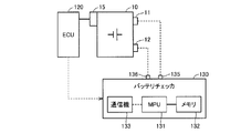
- FIG. 2 is a block diagram showing a configuration for evaluating the performance and value of the battery module shown in FIG.
- a battery sensor 15 is disposed in the battery module 10.
- the battery sensor 15 comprehensively indicates, for example, a voltage sensor, a current sensor, and a temperature sensor, and is configured to detect the voltage, current, and temperature of the battery module 10. Or while dividing the some battery cell 20 which comprises the battery module 10 into a some battery block, you may comprise so that a voltage, an electric current, and temperature may be detected for every battery block.
- detected values such as voltage, current, and temperature are also collectively referred to as “battery data”.
- the ECU 120 is configured to monitor and control the charging state on board based on the battery data detected by the battery sensor 15 when the battery module 10 is used. For example, the ECU 120 estimates the state of charge of the battery module 10 (typically, the SOC indicated by the ratio of the current remaining capacity to the full charge capacity) on-board. Alternatively, ECU 120 may sequentially set the upper limit values of the charging power and discharging power based on the estimated SOC, battery data, and the like.
- the ECU 120 can calculate battery parameters that can be used for performance evaluation of the battery module 10 in parallel with the use of the battery module 10, that is, on-board.
- a battery parameter an internal resistance and a full charge capacity can be calculated on board as disclosed in Japanese Patent Application Laid-Open No. 2007-195312 (Patent Document 3). This battery parameter is also used for deterioration diagnosis.
- the battery checker 130 includes a microprocessing unit (MPU) 131, a memory 132, a communication device 133, and test terminals 135 and 136.
- MPU microprocessing unit
- the communication device 133 is configured to be able to perform wired and / or wireless data communication with the ECU 120. Further, the MPU 131 can execute a predetermined control process accompanied by an operation by reading a program, data, or the like stored in the memory 132 in advance.
- Test terminals 135 and 136 can be electrically connected to the positive electrode terminal 11 and the negative electrode terminal 12 of the battery module 10 or the battery cell 20, respectively. That is, the battery checker 130 can evaluate the performance of the battery module 10 or the battery cell 20 by connecting the positive terminal 11 and the negative terminal 12 to the test terminals 135 and 136, respectively. Specifically, the battery checker 130 can measure the battery parameters of the battery module 10 or the battery cell 20 according to a processing procedure stored in advance as a program.
- FIG. 3 shows a configuration for measuring battery parameters of the battery module 10 or the battery cell 20 off-board by the battery checker 130.
- the positive and negative electrodes of battery module 10 or battery cell 20 are electrically connected to test terminals 135 and 136 of battery checker 130 via terminals 11 and 12 shown in FIG.
- the battery module 10 or the battery cell 20 is connected to the power source 200 and the load 210 via the switches 137 and 138. Discharge power from the battery module 10 or the battery cell 20 is supplied to the load 210.
- the power source 200 supplies charging power for the battery module 10 or the battery cell 20.
- the battery module 10 or the battery cell 20 is connected to the load 210 or the power source 200 according to the on / off control of the switches 137 and 138.
- the configuration for measuring with is not limited to FIG. That is, any configuration can be applied as long as the battery module 10 or the battery cell 20 can be intentionally charged and discharged.
- the current sensor 15a, the voltage sensor 15b, and the temperature sensor 15c perform battery data of the battery module 10 or the battery cell 20.
- the detected battery data is output to the MPU 131.
- the battery sensor 15 shown in FIG. 2 may be used as the current sensor 15a, the voltage sensor 15b, and the temperature sensor 15c. That is, the battery sensor 15, or the current sensor 15a, the voltage sensor 15b, and the temperature sensor 15c constitute a “detector”.
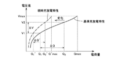
- the full charge capacity (FIG. 4) and the internal resistance (FIG. 5) are measured as battery parameters.
- the reference charge / discharge characteristic (solid line) of the secondary battery (battery module 10 or battery cell 20) is stored in battery checker 130 or ECU 120.
- the reference charge / discharge characteristics indicate the relationship between the charge amount and the voltage value (open voltage) in the reference state of the secondary battery.
- the charge amount Qmax corresponding to the maximum voltage value Vmax corresponds to the “full charge capacity” in the reference state.
- the reference charge / discharge characteristics can be obtained by experimental measurement in advance.
- FIG. 4 shows an example of the current charging / discharging characteristics (dashed line) of the secondary battery in which the deterioration has progressed to some extent.
- the charge amount at which the maximum voltage value Vmax is reached that is, the full charge capacity is reduced to Q'max.
- the change in the charge amount can be obtained by integrating the battery current Ib.
- the detected value with the current full charge capacity Q'max can be used as the battery parameter. It should be noted that the change in the full charge capacity can be obtained without necessarily setting the secondary battery to the full charge state.
- ⁇ Q ′ Q2′ ⁇ Q1 ′.
- the secondary battery has an internal resistance caused by a positive electrode material, a negative electrode material, an electrolyte (electrolytic solution), and the like.
- the internal resistance increases as the secondary battery deteriorates.
- the internal resistance value can be derived based on a voltage value and a current value detected during a period in which current flows through the secondary battery. Specifically, the internal resistance value is a voltage drop caused by a current (charging current or load current) flowing through the secondary battery (battery module 10 or battery cell 20) and a current value corresponding to the voltage drop. It can be derived from the ratio.
- the battery checker 130 or the ECU 120 acquires the battery voltage Vb (voltage value) and the battery current Ib (current value) in the battery data during a period in which the current flows through the battery module 10 or the battery cell 20. Then, after acquiring the battery voltage Vb and the battery current Ib a plurality of times, a linear function for the current value is derived so that the correlation value becomes the highest.
- the “slope” of the derived linear function corresponds to the value of the internal resistance. Since the internal resistance value increases as the battery deteriorates, the slope of the linear function increases as shown in FIG.
- the battery checker 130 can also read from the ECU 120 battery parameters measured by the ECU 120 onboard when the battery module 10 is used by communication with the ECU 120 by the communication device 133.
- Whether or not the battery module 10 needs to be replaced is determined by deterioration diagnosis based on battery parameters. Alternatively, the necessity of replacement may be determined simply based on the usage period or the like.
- the battery module 10 that needs to be replaced is once removed from the apparatus and reused.
- the battery module 10 is reused after replacing only a part of the plurality of battery cells 20 that has deteriorated.
- the battery module 10 is disassembled by removing the restraining band 42. Then, after replacing some of the plurality of battery cells 20, the battery module 10 is again restrained by the restraining band 42. Then, the re-constrained battery module 10 is attached to the apparatus again and used.
- the battery parameters described above can be measured before the battery module 10 is disassembled.
- battery parameters can be measured for each unit (for example, the above-described battery block) in which battery data (particularly, voltage and temperature) can be individually detected. It is also possible to acquire battery parameters for each battery cell 20 using the battery checker 130 after the battery module 10 is disassembled. Furthermore, the battery checker 130 can also measure the battery parameters of the battery cell 20 newly used by replacement in advance.
- the battery parameter for the entire battery module 10 to be reused is calculated as the battery parameter set value measured before reconstraining the battery module 10, and the value is calculated based on the calculated battery parameter. It is also possible.
- the internal resistance may change greatly between before re-restraint (including before disassembly and during use) and after re-restraint through disassembly and re-restraint of the battery module 10.
- an internal pressure is generated by the generation of gas in each battery cell 20 after use, so that the internal state of each battery cell 20 is changed by changing the contact state between the battery cells 20.
- the internal resistance is likely to change.
- the full charge capacity of each battery cell 20 it is predicted that the change between before re-restraint and after re-restraint is small compared to the internal resistance.
- the secondary battery value calculation technique according to the present embodiment, at least some of the battery parameters of the battery module 10 to be reused are measured after re-binding.
- FIG. 6 is a flowchart showing the processing procedure of the secondary battery value calculation method according to the embodiment of the present invention.
- battery checker 130 measures the battery parameters of battery module 10 before disassembly in step S100.
- the battery checker 130 may read out the battery parameter measured on board when the battery module 10 is used from the ECU 120 without directly measuring the battery parameter.
- step S110 the battery module 10 is disassembled by removing the restraining member. As a result, replacement in units of 20 battery cells is possible.
- step S120 the battery cell 20 in which deterioration progresses among the whole battery cells 20, is replaced
- the battery cell that needs to be replaced is determined based on the battery parameter acquired in step S100, for example.
- the battery cell that needs to be replaced may be determined according to the diagnostic code generated when the battery module 10 is used, regardless of the battery parameter.
- the battery parameters of each battery cell 20 may be measured after disassembly by switching the order of steps S100 and S110.
- the battery cell that needs to be replaced can be determined based on the battery parameters measured after disassembly.
- step S100 measures the battery parameter of the battery module 10 or the battery cell 20 “before re-binding” at the time of reuse.
- the measurement before re-restraining includes the measurement when the battery module 10 is used (on-board).
- step S130 the battery module 10 is assembled by restraining all the battery cells 20 including the battery cell after replacement by a restraining member. Thereby, the battery module 10 is restrained again.
- step S140 the battery checker 130 detects the battery data of the battery module 10 after the re-restraint by the charge / discharge test shown in FIG.
- step S150 the battery checker 130 measures the battery parameters after re-binding based on the battery data detected in step S140.
- the battery parameter measured in step S140 includes at least internal resistance.
- step S160 the battery checker 130 evaluates the value of the battery module 10 to be reused by reflecting the re-constrained battery parameters.
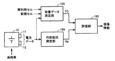
- FIG. 7 is a functional block diagram for explaining the configuration of the secondary battery value calculation device according to the first embodiment of the present invention.
- Each functional block shown in FIG. 7 is realized by the MPU 131 executing a predetermined program, for example.
- the capacity data measurement unit 150 measures the full charge capacity TC of the battery module 10.
- the full charge capacity TC may be measured either before re-restraint or after re-restraint. For example, when the full charge capacity is measured before reconstraining in order to determine the replacement object, this measured value can be used as it is. That is, it is possible to obtain the full charge capacity TC according to the total full charge capacity of each of the battery cell 20 to be reused and the battery cell 20 to be newly used.
- the capacity data measurement unit 150 corresponds to the “first measurement unit” when measuring the full charge capacity after re-restraining, and the “second measurement unit” when measuring the full charge capacity before re-restraining.
- the internal resistance measurement unit 160 measures the internal resistance Rp after re-restraining based on battery data when the re-restrained battery module 10 is charged or discharged. As described above, since the internal resistance should be measured after re-restraining, the internal resistance measurement unit 160 corresponds to the “first measurement unit”.
- the evaluation unit 190 generates value information of the battery module 10 that is re-constrained and reused based on the measured internal resistance Rp and full charge capacity TC.
- the value information includes a reusable period of the battery module 10 set based on the internal resistance and the full charge capacity, price information set in accordance with the reusable period, and the like.
- the first embodiment of the present invention it is possible to accurately calculate the value of the battery module by accurately grasping the battery parameter of the battery module that is reused with disassembly and re-binding. In particular, it is possible to prevent erroneous calculation of the value of the battery module 10 to be reused even when the internal resistance changes greatly before and after the re-restraint due to the change of the restraint state of each battery cell 20.
- the time required for calculating the value of the battery module 10 to be reused is shortened.
- each battery cell 20 constituting the battery module 10 is a lithium ion secondary battery.
- FIG. 8 is a functional block diagram for explaining the configuration of the secondary battery value calculation device according to the second embodiment of the present invention.
- the secondary battery value calculation apparatus further includes a lithium deposition amount measuring unit 170 in addition to the configuration shown in the first embodiment shown in FIG. Then, the evaluation unit 190 generates value information of the battery module 10 to be reused by further using the parameter ⁇ Qs (Li) indicating the lithium deposition amount in addition to the full charge capacity TC and the internal resistance Rp.
- the positive electrode capacity retention rate k1, the negative electrode capacity retention rate k2, and the battery capacity fluctuation amount (shift capacity) ⁇ Qs are calculated based on the deterioration diagnosis for each battery module 10 (for each battery block) or each battery cell 20.
- the positive electrode capacity retention rate k1 is defined by the ratio of the positive electrode capacity in the deteriorated state to the positive electrode capacity in the initial state.
- the negative electrode capacity retention ratio k2 is defined by the ratio of the negative electrode capacity in the deteriorated state to the negative electrode capacity in the initial state.
- the deviation capacity is a deviation capacity corresponding to the composition between the positive electrode and the negative electrode, and corresponds to “battery capacity fluctuation amount”.
- a lithium ion secondary battery includes a negative electrode, a separator containing an electrolytic solution, and a positive electrode (all not shown).
- Each of the negative electrode and the positive electrode is composed of an aggregate of spherical active materials.
- a chemical reaction is performed on the negative electrode active material interface to release lithium ions Li + and electrons e ⁇ .
- a chemical reaction that absorbs lithium ions Li + and electrons e ⁇ is performed on the interface of the positive electrode active material.
- a reaction opposite to the above-described reaction is performed.
- the negative electrode is provided with a current collecting plate that absorbs electrons
- the positive electrode is provided with a current collecting plate that emits electrons.
- the negative electrode current collector plate is made of, for example, copper and connected to the negative electrode terminal.
- the positive electrode current collector plate is made of aluminum, for example, and is connected to the positive electrode terminal.
- the lithium ion secondary battery is charged and discharged by transferring lithium ions between the positive electrode and the negative electrode through the separator.
- the state of charge inside the lithium ion secondary battery varies depending on the lithium concentration distribution in the active material of each of the positive electrode and the negative electrode. This lithium contributes to the reaction of the lithium ion secondary battery.
- the output voltage V of the lithium ion secondary battery is represented by the following formula (1).
- V OCV ( ⁇ 1, ⁇ 2) ⁇ R ⁇ I (1)
- OCV is the open-circuit voltage of the lithium ion secondary battery
- R is the resistance of the entire lithium ion secondary battery
- I is the battery current flowing through the lithium ion secondary battery.
- the resistance R includes a pure electric resistance against electron movement at the negative electrode and the positive electrode and a charge transfer resistance that acts equivalently as an electric resistance when a reaction current is generated at the active material interface.
- ⁇ 1 is a local SOC (State Of Charge) on the surface of the positive electrode active material
- ⁇ 2 is a local SOC on the surface of the negative electrode active material.
- the resistor R has a characteristic that changes according to changes in ⁇ 1, ⁇ 2, and battery temperature. In other words, the resistance R can be expressed as a function of ⁇ 1, ⁇ 2 and battery temperature.
- Local SOCs ⁇ 1 and ⁇ 2 are represented by the following equation (2).
- Cse, i is the lithium concentration (average value) at the interface of the active material (positive electrode or negative electrode)
- Cs, i, max is the critical lithium concentration in the active material (positive electrode or negative electrode).
- the limit lithium concentration is the upper limit value of the lithium concentration in the positive electrode and the negative electrode.
- FIG. 9 is a conceptual diagram showing a change characteristic of the open-circuit voltage with respect to a change in local SOC.
- open-circuit voltage OCV of the lithium ion secondary battery is expressed as a potential difference between positive electrode open potential U1 and negative electrode open potential U2.
- the positive electrode open-circuit potential U1 has a characteristic that changes according to local SOC ⁇ 1 on the surface of the positive electrode active material
- the negative electrode open-circuit potential U2 has a characteristic that changes according to local SOC ⁇ 2 on the surface of the negative electrode active material. Yes.
- the initial state refers to a state in which the lithium ion secondary battery has not deteriorated, for example, a state immediately after manufacturing the lithium ion secondary battery.
- the characteristic indicating the relationship between the local SOC ⁇ 2 and the negative electrode open potential U2 (the value of U2 shown in FIG. 9). Curve). Data indicating these characteristics (U1, U2) can be stored in advance in a memory as a map.
- the open circuit voltage OCV of a lithium ion secondary battery has a characteristic of decreasing as the discharge proceeds.
- the amount of voltage drop with respect to the same discharge time is larger than that in an initial state lithium ion secondary battery. This indicates that the deterioration of the lithium ion secondary battery causes a decrease in full charge capacity and a change in open-circuit voltage characteristics.
- changes in open-circuit voltage characteristics accompanying the deterioration of the lithium ion secondary battery are modeled as two phenomena that are considered to occur inside the deteriorated lithium ion secondary battery. These two phenomena are a decrease in single electrode capacity at the positive electrode and the negative electrode, and a corresponding shift in composition between the positive electrode and the negative electrode.
- the decrease in single electrode capacity indicates a decrease in lithium acceptance capacity in each of the positive electrode and the negative electrode.
- the decrease in lithium-accepting ability means that the number of active materials that function effectively for charging and discharging is decreasing.
- FIG. 10 is a graph schematically showing a change in the unipolar open potential due to a decrease in the unipolar capacity.
- the capacity corresponding to the local SOC ⁇ 1 of the positive electrode changes from Q_H11 to Q_H12. Further, when the lithium acceptability is reduced in the negative electrode, the capacity corresponding to the local SOC ⁇ 2 of the negative electrode changes from Q_H21 to Q_H22.
- a curve indicating the relationship between the negative electrode capacity and the negative electrode open potential is a lithium ion secondary as shown in FIG. As the battery deteriorates, it is in a contracted state with respect to the initial curve.
- FIG. 11 is a conceptual diagram schematically showing the relationship between the composition correspondence shift between the positive electrode and the negative electrode and the open-circuit potential.
- the difference in composition is that the combination of the positive electrode composition ( ⁇ 1) and the negative electrode composition ( ⁇ 2) is different from the initial state of the lithium ion secondary battery when charging and discharging are performed using the positive electrode and negative electrode pairs. It shows that it has shifted.
- the curves showing the relationship between the monopolar compositions ⁇ 1 and ⁇ 2 and the open circuit potentials U1 and U2 are the same as the curves shown in FIG.
- the axis of the negative electrode composition ⁇ 2 shifts by ⁇ 2 in the direction in which the positive electrode composition ⁇ 1 decreases.
- the curve indicating the relationship between the negative electrode composition ⁇ 2 and the negative electrode open-circuit potential U2 shifts in a direction in which the positive electrode composition ⁇ 1 decreases with respect to the curve in the initial state by ⁇ 2.
- the composition of the negative electrode corresponding to the positive electrode composition ⁇ 1fix is “ ⁇ 2fix_ini” when the lithium ion secondary battery is in the initial state, but becomes “ ⁇ 2fix” after the lithium ion secondary battery is deteriorated.
- the negative electrode composition ⁇ L2 shown in FIG. 9 is set to 0, which indicates a state in which all lithium in the negative electrode has been removed.
- the above-described two deterioration phenomena are modeled by introducing the three deterioration parameters of the positive electrode capacity retention ratio k1, the negative electrode capacity retention ratio k2, and the positive and negative electrode composition correspondence deviation amount ⁇ Qs.
- the positive electrode capacity retention rate k1 is defined by the ratio of the positive electrode capacity in the deteriorated state to the positive electrode capacity in the initial state.
- the positive electrode capacity is decreased by an arbitrary amount from the capacity in the initial state after the lithium ion secondary battery is in a deteriorated state.
- the positive electrode capacity retention ratio k1 is expressed by the following formula (3).
- Q1_ini indicates a positive electrode capacity (Q_H11 shown in FIG. 10) when the lithium ion secondary battery is in an initial state, and ⁇ Q1 indicates a decrease amount of the positive electrode capacity when the lithium ion secondary battery deteriorates. ing.
- the positive electrode capacity Q1_ini can be obtained in advance by experiments.
- the negative electrode capacity retention ratio k2 is defined by the ratio of the negative electrode capacity in the deteriorated state to the negative electrode capacity in the initial state.
- the negative electrode capacity is decreased by an arbitrary amount from the capacity in the initial state after the lithium ion secondary battery is in a deteriorated state.
- the negative electrode capacity retention ratio k2 is expressed by the following formula (4).
- Q2_ini indicates a negative electrode capacity (Q_H21 in FIG. 10) when the lithium ion secondary battery is in an initial state, and ⁇ Q2 indicates a decrease amount of the negative electrode capacity when the lithium ion secondary battery deteriorates. Yes.
- the negative electrode capacity Q2_ini can be obtained in advance by experiments.
- FIG. 12 is a schematic diagram for explaining a shift in composition correspondence due to deterioration.
- the capacity when the negative electrode composition ⁇ 2 is 1 is (Q2_ini ⁇ Q2).
- the composition-corresponding deviation capacity ⁇ Qs between the positive electrode and the negative electrode is a capacity corresponding to the deviation amount ⁇ 2 of the negative electrode composition axis with respect to the positive electrode composition axis.
- the positive electrode composition ⁇ 1fix_ini corresponds to the negative electrode composition ⁇ 2fix_ini.
- the positive electrode composition ⁇ 1fix corresponds to the negative electrode composition ⁇ 2fix.
- the composition correspondence shift is based on the positive electrode composition ⁇ 1fix in the initial state. That is, the positive electrode composition ⁇ 1fix and the positive electrode composition ⁇ 1fix_ini have the same value.
- the positive electrode composition ⁇ 1fix and the negative electrode composition ⁇ 2fix after deterioration of the lithium ion secondary battery are expressed by the following formulas (7), ( 8).
- Amount of lithium released from the positive electrode (1 ⁇ 1fix) ⁇ k1 ⁇ Q1_ini (9)
- the value of (1- ⁇ 1fix) indicates the change in the positive electrode composition due to deterioration of the lithium ion secondary battery
- the value of (k1 ⁇ Q1_ini) indicates the positive electrode capacity after deterioration of the lithium ion secondary battery. ing.
- the negative electrode composition ⁇ 2fix is expressed by the following formula (10).
- ⁇ 2fix (1 ⁇ 1fix) ⁇ k1 ⁇ Q1_ini / (k2 ⁇ Q2_ini) (10)
- the value of (k2 ⁇ Q2_ini) indicates the negative electrode capacity after deterioration of the lithium ion secondary battery.
- the negative electrode composition ⁇ 2fix is expressed by the following formula (11).
- ⁇ 2fix (1 ⁇ 1fix) ⁇ k1 ⁇ Q1_ini / (k2 ⁇ Q2_ini) ⁇ 2 (11)
- the shift amount ⁇ 2 corresponding to the composition can be expressed by using the shift capacity ⁇ Qs corresponding to the composition by the equation (6).
- the negative electrode composition ⁇ 2fix is expressed by the above formula (8).
- the open circuit voltage OCV when the lithium ion secondary battery is in the deteriorated state is expressed as a potential difference between the positive electrode open potential U11 and the negative electrode open potential U22 in the deteriorated state. That is, if the three deterioration parameters k1, k2, and ⁇ Qs are estimated, the negative electrode open potential U22 when the lithium ion secondary battery is in a deteriorated state can be identified, and the potential difference between the negative electrode open potential U22 and the positive electrode open potential U11 is opened.
- the voltage OCV can be calculated.
- deterioration of lithium ion secondary batteries includes deterioration due to lithium precipitation and deterioration due to wear (wear deterioration). By grasping (estimating) these deteriorations separately, The deterioration state can be determined in detail.
- Wear deterioration is deterioration other than deterioration due to precipitation of lithium among deterioration of a lithium ion secondary battery, and the performance (acceptability of lithium) of the positive electrode and the negative electrode is deteriorated due to energization or standing.
- the active material of the positive electrode or the negative electrode is worn as an example of wear deterioration.
- the deterioration due to the deposition of lithium refers to a deterioration in which lithium ions used in the battery reaction change to a by-product (mainly metallic lithium) and do not contribute to the battery reaction.
- the open circuit voltage OCV when the lithium ion secondary battery is not deteriorated coincides with the open circuit voltage OCV in the lithium ion secondary battery in the initial state. That is, when the positive electrode capacity retention ratio k1 and the negative electrode capacity retention ratio k2 are 1, and the deviation capacity ⁇ Qs corresponding to the composition is 0, the open circuit voltage OCV calculated (estimated) by the above-described explanation is the initial state (new article) ) And the value (measured value) when the open-circuit voltage OCV of the lithium ion secondary battery is measured.
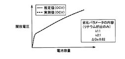
- FIG. 13 shows the relationship between the capacity (SOC) of the lithium ion secondary battery and the open circuit voltage OCV (that is, the open circuit voltage characteristic).
- the curve shown in FIG. 13 and the like showing the open-circuit voltage characteristics is also referred to as “open-circuit voltage curve”.
- the dotted line in FIG. 13 is an open circuit voltage curve (actually measured value), and the solid line is an open circuit voltage curve (estimated value).
- the open-circuit voltage curve (estimated value) overlaps with the open-circuit voltage curve (actually measured value).
- the vertical axis indicates the open circuit voltage OCV
- the horizontal axis indicates the capacity of the lithium ion secondary battery.
- the open circuit voltage (actually measured value) OCV changes.
- the dotted line in FIG. 14 shows a lithium ion secondary battery in which only deterioration due to precipitation of lithium has occurred, in other words, a lithium ion secondary battery in which no wear deterioration has occurred.
- the result of having measured the open circuit voltage curve (actual value) using is shown.
- the lithium ion secondary battery is maintained at a low temperature, wear deterioration can be suppressed, and only lithium deposition can be performed while the wear deterioration is suppressed.
- wear deterioration can be suppressed, and only lithium deposition can be performed while the wear deterioration is suppressed.
- the open-circuit voltage curve (estimated value) can be made to substantially match the open-circuit voltage curve (actually measured value) shown in FIG.
- the three degradation parameters can be searched so that the open-circuit voltage curve (estimated value) substantially matches the open-circuit voltage curve (actually measured value).
- FIG. 14 shows a state in which the open circuit voltage (actually measured value) OCV and the open circuit voltage (estimated value) OCV substantially match.
- the positive electrode capacity retention ratio k1 is “1”
- the negative electrode capacity retention ratio k2 is “1”
- the composition-related deviation capacity ⁇ Qs is “0.62”. It has become.
- the dotted line in FIG. 15 shows the result of measuring an open-circuit voltage curve (actually measured value) using a lithium ion secondary battery in which only wear deterioration has occurred, in other words, a lithium ion secondary battery in which lithium is not deposited. Is shown.
- the vertical axis represents the open circuit voltage OCV
- the horizontal axis represents the capacity of the lithium ion secondary battery.
- the lithium ion secondary battery is maintained at a high temperature, it is possible to suppress the precipitation of lithium, and it is possible to generate only the wear deterioration while suppressing the precipitation of lithium.
- the set temperature can be set to 50 degrees, for example. Thereby, only wear deterioration can be generated in the lithium ion secondary battery.
- FIG. 15 shows a state where the open-circuit voltage (actual value) OCV and the open-circuit voltage (estimated value) OCV substantially match.
- the positive electrode capacity retention rate k1 is “0.85”
- the negative electrode capacity retention rate k2 is “0.97”
- the composition-related shift capacity ⁇ Qs is “ 0.05 ".
- the precipitation of lithium may be, for example, a case where lithium ions released from the positive electrode during charging are not taken into the negative electrode. In this case, the composition correspondence between the positive electrode and the negative electrode is shifted, and the shift capacity ⁇ Qs is changed. In addition, in the state where only lithium deposition occurs, the capacity of accepting lithium in the positive electrode and the negative electrode does not decrease, so that each of the positive electrode capacity retention rate k1 and the negative electrode capacity retention rate k2 is maintained at “1”. become.
- the shift capacity ⁇ Qs includes the shift capacity ⁇ Qs (Li) due to deterioration of lithium deposition and the shift capacity ⁇ Qs (W) due to wear deterioration. It becomes possible to estimate the amount of precipitation quantitatively.
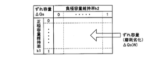
- This map shows the correspondence relationship between the positive electrode capacity retention rate k1 and the negative electrode capacity retention rate k2 and the composition-compatible shift capacity ⁇ Qs when only wear deterioration occurs in the lithium ion secondary battery.
- This map can be created in advance based on experimental results. As described above, if the lithium ion secondary battery is maintained at a high temperature, it is possible to prevent lithium precipitation and to perform an experiment that causes only wear deterioration.
- the capacity (full charge capacity) of the lithium ion secondary battery is decreased step by step by a predetermined amount. And whenever the capacity
- deterioration parameters positive electrode capacity maintenance rate k1, negative electrode capacity maintenance rate k2, and open circuit voltage (estimated value) OCV
- deterioration parameters positive electrode capacity maintenance rate k1, negative electrode capacity maintenance rate k2, and open circuit voltage (estimated value) OCV
- the wear deterioration map shown in FIG. 16 shows a correspondence relationship between the positive electrode capacity retention rate k1 and the negative electrode capacity retention rate k2 and the displacement capacity ⁇ Qs (W).
- the positive electrode capacity retention rate k1 and the negative electrode capacity retention rate k2 are expressed as follows. If selected, the displacement capacity ⁇ Qs (W) due to wear deterioration can be specified.
- the wear deterioration map can be stored in a memory.
- the open-circuit voltage curve can be obtained by charging / discharging at least the battery module 10 or the battery cell 20 (lithium ion secondary battery) in a state where the use is finished.
- FIG. 17 is a flowchart showing a control processing procedure by the MPU 131 for acquiring the deterioration parameter of the lithium ion secondary battery off-board by the battery checker 130.
- step S151 MPU 131, based on the output of voltage sensor 15b, opens voltage (actually measured value) of a lithium ion secondary battery (battery module 10 or battery cell 20) that is subject to deterioration determination.
- Measure OCV Specifically, an open-circuit voltage curve (actual value) can be obtained by measuring an open-circuit voltage (actual value) OCV while charging and discharging a lithium ion secondary battery.
- step S152 the MPU 131 changes the three deterioration parameters (the positive electrode capacity maintenance rate k1, the negative electrode capacity maintenance rate k2, and the shift capacity ⁇ Qs) as appropriate, so that the open circuit voltage (estimated value) OCV specified by the three deterioration parameters is Then, it is determined whether or not it matches the open circuit voltage (actual value) OCV obtained in step S151.
- the three deterioration parameters the positive electrode capacity maintenance rate k1, the negative electrode capacity maintenance rate k2, and the shift capacity ⁇ Qs
- FIG. 18 shows an example of the relationship between open-circuit voltage (estimated value) OCV indicated by a dotted line and open-circuit voltage (actually measured value) OCV indicated by a solid line.
- the open-circuit voltage (estimated value) OCV when the open-circuit voltage curve of the estimated value 1 is obtained, the open-circuit voltage (estimated value) OCV is higher than the open-circuit voltage (actually measured value) OCV. Reset the deterioration parameter.
- the open-circuit voltage curve of the estimated value 2 when the open-circuit voltage curve of the estimated value 2 is obtained, the open-circuit voltage (estimated value) OCV is lower than the open-circuit voltage (actually measured value) OCV. Reset the deterioration parameter. In this way, by repeatedly executing the setting of the deterioration parameter, the open circuit voltage (estimated value) OCV can be matched with the open circuit voltage (actually measured value) OCV.
- the MPU 131 specifies a deterioration parameter when the open circuit voltage (estimated value) OCV matches the open circuit voltage (actually measured value) OCV.
- the positive electrode capacity retention rate k1 the negative electrode capacity retention rate k2, and the shift capacity ⁇ Qs are determined.
- the shift capacity ⁇ Qs determined in step S152 is a shift capacity including both a shift capacity due to deterioration of lithium deposition and a shift capacity due to wear deterioration.
- an open circuit voltage (allowable error) is set. It can be determined whether or not the estimated value) OCV and the open circuit voltage (actually measured value) OCV match.
- step S153 the MPU 131 specifies the displacement capacity ⁇ Qs (W) using the positive electrode capacity retention rate k1 and the negative electrode capacity retention rate k2 determined in step S152 and the wear deterioration map (FIG. 16). Further, in step S154, the MPU 131 obtains a difference between the displacement capacity ⁇ Qs obtained in step S152 and the displacement capacity ⁇ Qs (W) obtained in step S153. Thereby, the deviation capacity ⁇ Qs (Li) due to the deterioration of lithium deposition is calculated.
- the lithium ion secondary battery (battery module 10 or battery cell 20) off-board, deterioration parameters such as the positive electrode capacity maintenance rate k1, the negative electrode capacity maintenance rate k2, and the deviation capacity are obtained. ⁇ Qs can be acquired. Further, the lithium ion secondary battery is disassembled and separated by separating the shift capacity ⁇ Qs into a shift capacity ⁇ Qs (W) due to wear deterioration and a shift capacity ⁇ Qs (Li) due to deterioration of lithium deposition. Lithium precipitation can be estimated quantitatively without analysis.
- the lithium deposition amount measuring unit 170 measures the deviation capacity ⁇ Qs (Li) resulting from the deterioration of the lithium deposition as a parameter indicating the lithium deposition amount by the above-described degradation diagnosis.
- the lithium deposition amount measuring unit 170 can measure the parameter ⁇ Qs (Li) by a charge / discharge test using the battery checker 130 before and after the re-restraint. That is, the lithium deposition amount measurement unit 170 corresponds to the “first measurement unit” when measuring the full charge capacity after re-restraining, and “second second” when measuring the full charge capacity before re-restraining. Corresponds to "measurement unit"
- the evaluation unit 190 reflects the battery parameter ⁇ Qs (Li) indicating the lithium deposition amount and generates value information of the battery module 10 to be reused.
- the value of the battery module 10 to be reused can be further increased by further reflecting the amount of deposited lithium that greatly affects the performance (remaining life) of the lithium ion secondary battery. It can be calculated accurately.
- the processing described in the second embodiment is performed on-board.
- the controller (ECU 120) that controls charging / discharging of the lithium ion secondary battery performs the same processing as in the second embodiment.
- An electric vehicle capable of charging an in-vehicle battery (lithium ion secondary battery) from a power source outside the vehicle is used.
- Such vehicles include PHV (Plug-in Hybrid Vehicle) and EV (Electric Vehicle).
- FIG. 19 is a flowchart showing a control processing procedure for acquiring on-board deterioration parameters of a lithium ion secondary battery that is an in-vehicle battery.
- the control process shown in FIG. 19 is performed by a controller (for example, ECU 120 shown in FIG. 2) mounted on the vehicle.
- ECU 120 measures the open-circuit voltage (actually measured value) OCV and the current integrated amount of the lithium ion secondary battery (battery module 10) based on the outputs of the voltage sensor and the current sensor included in the battery sensor 15 in step S201. Specifically, when charging a lithium ion secondary battery mounted on a vehicle, an open circuit voltage (actual value) with respect to a change in battery capacity is measured by appropriately measuring an open circuit voltage (actual value) OCV and a current integrated amount. A curve indicating the change in OCV (an open-circuit voltage curve as an actual measurement value) can be acquired.
- ECU 120 sets (selects) candidates for deterioration parameters (positive electrode capacity maintenance rate k1, negative electrode capacity maintenance rate k2 and displacement capacity ⁇ Qs) for specifying the open circuit voltage (estimated value) OCV in step S202.
- the deterioration parameter can be set by various methods, it is preferable to employ a method for efficiently performing arithmetic processing for setting the deterioration parameter.
- the selection range of the deterioration parameter a range when wear deterioration or deterioration due to lithium deposition actually occurs can be specified in advance based on experiments or the like.
- the positive electrode capacity retention ratio k1 and the negative electrode capacity retention ratio k2 depend only on the wear deterioration, the positive electrode capacity retention ratio k1 and the negative electrode capacity retention ratio k2 are changed within a range where actual wear deterioration occurs. be able to.
- the positive electrode capacity retention ratio k1 and the negative electrode capacity retention ratio k2 can be specified, the displacement capacity ⁇ Qs (W) due to wear deterioration can be specified using the wear deterioration map (FIG. 16). If the shift capacity ⁇ Qs (W) can be specified, it is only necessary to change the shift capacity ⁇ Qs (Li).
- step S203 ECU 120 calculates a characteristic (open-circuit voltage curve as an estimated value) indicating a change in open-circuit voltage (estimated value) OCV with respect to a change in capacity based on the deterioration parameter set in step S202.
- step S204 the ECU 120 calculates an error between the open-circuit voltage curve (estimated value) calculated in step S203 and the open-circuit voltage curve (measured value) obtained in step S201.
- This error includes a voltage error and a capacitance error.
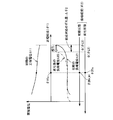
- the voltage error ⁇ V (see FIG. 20) can be calculated by comparing the open-circuit voltage curve (estimated value) and the open-circuit voltage curve (actually measured value).
- the voltage error ⁇ V may be a voltage error in a specific battery capacity, or may be an average value of voltage errors between two open-circuit voltage curves.
- the capacity error ⁇ Q can be obtained by the method described below, for example.
- the capacity Q1 between the open circuit voltage before charging and the open circuit voltage after charging is calculated using the open circuit voltage curve (estimated value).
- the charging capacity Q2 can be calculated from the current integrated value by detecting the current and measuring the current integrated value from the start to the end of charging.
- ) of the capacitance error ⁇ Q can be obtained by obtaining the difference between the capacitance Q1 and the capacitance Q2.
- the lithium ion secondary battery is in a relaxed state, and an accurate open-circuit voltage can be measured in a state where there is no difference in lithium concentration. it can.
- An example of the case where the lithium ion secondary battery is in a relaxed state is when the vehicle is stopped for a predetermined time or more. Thereby, the open circuit voltage (measured value) OCV when the lithium ion secondary battery is at a specific capacity can be obtained.
- the voltage error ⁇ V can be obtained by comparing the open-circuit voltage (measured value) and the open-circuit voltage curve (estimated value). Further, if a plurality of open-circuit voltages (actually measured values) are measured, the capacity error ⁇ Q can be obtained as described above. Specifically, the capacity Q1 between two open circuit voltages (actually measured values) is calculated using an open circuit voltage curve (estimated value). Further, if a current integrated value at the time of obtaining two open circuit voltages (actually measured values) is measured, the capacity Q2 can be calculated from the current integrated value. If the difference (
- step S205 the ECU 120 calculates an evaluation function f ( ⁇ V, ⁇ Q) for the voltage error ⁇ V and the capacity error ⁇ Q obtained in step S204.
- the evaluation function f ( ⁇ V, ⁇ Q) for example, a value obtained by weighting and adding to the voltage error ⁇ V and the capacity error ⁇ Q can be used.
- the ECU 120 determines whether or not the evaluation function f ( ⁇ V, ⁇ Q) calculated from the currently set deterioration parameter is smaller than the evaluation function f ( ⁇ V, ⁇ Q) calculated from the previously set deterioration parameter. Determine. If the current evaluation function f ( ⁇ V, ⁇ Q) is smaller than the previous evaluation function f ( ⁇ V, ⁇ Q), the current evaluation function f ( ⁇ V, ⁇ Q) is stored in the memory. If the current evaluation function f ( ⁇ V, ⁇ Q) is larger than the previous evaluation function f ( ⁇ V, ⁇ Q), the previous evaluation function f ( ⁇ V, ⁇ Q) remains stored in the memory.
- ECU 120 determines whether or not the deterioration parameter is changed in all search ranges in step S206, and if the deterioration parameter is changed in all search ranges, the process proceeds to step S207. On the other hand, if it is not changed in all search ranges, ECU 120 returns the process to step S202.
- step S202 to step S206 The process from step S202 to step S206 is repeated until the deterioration parameter is changed over the entire search range. Then, the evaluation function f ( ⁇ V, ⁇ Q) that is the minimum value is specified, the open-circuit voltage curve from which the evaluation function (minimum value) is obtained can be specified, and the degradation parameter that defines the open-circuit voltage curve (estimated value) ( k1, k2, ⁇ Qs) can be specified.
- the deterioration parameter whose evaluation function shows the minimum value, it is possible to improve the accuracy of determination of the deterioration state (wear deterioration and deterioration due to lithium precipitation).
- the specified shift capacity ⁇ Qs includes a shift capacity ⁇ Qs (W) due to wear deterioration and a shift capacity ⁇ Qs (Li) due to deterioration of lithium deposition. Therefore, ECU 120 wears in step S207 using the deterioration parameters (positive electrode capacity maintenance rate k1 and negative electrode capacity maintenance rate k2) determined in the processing in steps S202 to S206 and the wear deterioration map (FIG. 10).
- the shift capacity ⁇ Qs (W) due to deterioration is specified.
- step S208 the ECU 120 calculates the difference between the displacement capacity ⁇ Qs specified in the processing of steps S202 to S206 and the displacement capacity ⁇ Qs (W) obtained in step S207, thereby causing the displacement due to lithium deposition.
- the capacity ⁇ Qs (Li) is calculated.
- the positive electrode capacity retention rate k1, the negative electrode capacity retention rate k2, and the deviation are determined by the deterioration diagnosis based on the open-circuit voltage characteristics for the lithium ion secondary battery mounted on the electric vehicle.
- the capacity ⁇ Qs can be acquired on-board.
- deterioration parameters are acquired on-board based on open-circuit voltage characteristics.
- the parameter ⁇ Qs (Li) indicating the amount of lithium deposition can be measured.
- the lithium deposition amount measuring unit 170 in FIG. 8 can obtain the parameter ⁇ Qs (Li) by data communication between the battery checker 130 and the ECU 120. Since other operations are similar to those of the second embodiment, detailed description will not be repeated.
- the battery parameter indicating the lithium deposition amount that greatly affects the performance (remaining life) of the lithium ion secondary battery is measured off-board by the battery checker 130. Can be obtained without executing. Therefore, as compared with the second embodiment, the time required for calculating the value of the battery module 10 to be reused is shortened.
- the battery parameter ⁇ Qs (Li) can be obtained off-board or on-board, and can be measured at an arbitrary timing.
- the lithium deposition state in the lithium ion secondary battery may change depending on environmental conditions. For example, it is known that the amount of lithium deposition decreases in the battery cell 20 that has been left for a long time under a high temperature state. Therefore, the battery parameter ⁇ Qs (Li) is preferably measured before and after the re-restraining step (step S130 in FIG. 6), preferably after re-restraining.
- the secondary battery (lithium ion secondary battery) to be subjected to deterioration determination is a secondary battery mounted on an electric vehicle. Will be described in a confirming manner that is not limited to such cases. That is, the value calculation technique according to the present invention can be applied to reuse of a secondary battery that is used in a state where a plurality of battery cells are constrained by a constraining member.
- the full charge capacity, the internal resistance, and the lithium deposition amount are exemplified as the battery parameters, but other battery parameters are employed to execute the value calculation of the secondary battery according to the present invention. It is also possible.
- the diffusion coefficient Ds of a reaction participating substance for example, lithium in a lithium ion secondary battery
- JP-A-2008-241246 can be used as a deterioration index.
- the positive electrode capacity retention rate k1, the negative electrode capacity retention rate k2, the displacement capacity ⁇ Qs, and the displacement capacity ⁇ Qs (W) resulting from wear deterioration described in the second embodiment can be added to the battery parameters.
- the present invention is applied to a secondary battery reuse technique used as an assembled battery in which a plurality of battery cells are restrained by a restraining member.
Landscapes
- Chemical & Material Sciences (AREA)
- Chemical Kinetics & Catalysis (AREA)
- Electrochemistry (AREA)
- General Chemical & Material Sciences (AREA)
- Engineering & Computer Science (AREA)
- Manufacturing & Machinery (AREA)
- Physics & Mathematics (AREA)
- General Physics & Mathematics (AREA)
- Secondary Cells (AREA)
- Battery Mounting, Suspending (AREA)
Abstract
Description
図1は、本発明の実施の形態による二次電池の価値算定技術が適用される組電池である電池モジュール10の構成例を示す概略斜視図である。
出力電圧や出力密度が高い利点より、リチウムイオン二次電池の使用が拡大されている。その一方で、リチウムイオン二次電池では、金属リチウムの析出が電池劣化に大きな影響を及ぼすことが知られている。このため、リチウムイオン二次電池の劣化度合については、定量的に評価されたリチウム析出に基づいて評価することが好ましい。
実施の形態2では、リチウムイオン二次電池のリチウム析出量を定量的に推定する手法と、推定されたリチウム析出量に基づく、再使用される二次電池の価値算出技術とについて説明する。すなわち、実施の形態2では、電池モジュール10を構成する各電池セル20は、リチウムイオン二次電池である。
実施の形態2では、電池モジュール10(電池ブロックごと)または電池セル20ごとの劣化診断により、正極容量維持率k1、負極容量維持率k2および電池容量変動量(ずれ容量)ΔQsを算出する。
V=OCV(θ1,θ2)-R×I ・・・(1)
ここで、OCVは、リチウムイオン二次電池の開放電圧、Rは、リチウムイオン二次電池の全体における抵抗、Iは、リチウムイオン二次電池に流れる電池電流である。抵抗Rは、負極および正極で電子の移動に対する純電気的な抵抗と、活物質界面での反応電流発生時に等価的に電気抵抗として作用する電荷移動抵抗とが含まれる。
θi=Cse,i/Cs,i,max (i=1,2) ・・・(2)
ここで、Cse,iは、活物質(正極又は負極)の界面におけるリチウム濃度(平均値)であり、Cs,i,maxは、活物質(正極又は負極)における限界リチウム濃度である。限界リチウム濃度とは、正極や負極におけるリチウム濃度の上限値である。
図9を参照して、リチウムイオン二次電池の開放電圧OCVは、正極開放電位U1および負極開放電位U2の電位差として表される。正極開放電位U1は、正極活物質の表面における局所的SOCθ1に応じて変化する特性を有し、負極開放電位U2は、負極活物質の表面における局所的SOCθ2に応じて変化する特性を有している。
図10において、正極容量の軸におけるQ_L1は、リチウムイオン二次電池の初期状態において、図9の局所的SOC=θL1に対応する容量である。Q_H11は、リチウムイオン二次電池の初期状態において、図9の局所的SOC=θH1に対応する容量である。また、負極容量の軸におけるQ_L2は、リチウムイオン二次電池の初期状態において、図9の局所的SOC=θL2に対応する容量であり、Q_H21は、リチウムイオン二次電池の初期状態において、図9の局所的SOC=θH2に対応する容量である。
(0<k1<1)
ここで、Q1_iniは、リチウムイオン二次電池が初期状態にあるときの正極容量(図10に示すQ_H11)を示し、ΔQ1は、リチウムイオン二次電池が劣化したときの正極容量の減少量を示している。正極容量Q1_iniは、実験によって予め求めておくことができる。
(0<k2<1)
ここで、Q2_iniは、リチウムイオン二次電池が初期状態にあるときの負極容量(図10のQ_H21)を示し、ΔQ2は、リチウムイオン二次電池が劣化したときの負極容量の減少量を示している。負極容量Q2_iniは、実験によって予め求めておくことができる。
リチウムイオン二次電池が劣化状態となったときには、負極組成θ2が1であるときの容量は、(Q2_ini-ΔQ2)となる。また、正極および負極の間における組成対応ずれ容量ΔQsは、正極組成軸に対する負極組成軸のずれ量Δθ2に対応する容量である。これにより、下記式(5)の関係が成り立つ。
式(4)及び式(5)から下記式(6)が求められる。
=k2×Q2_ini×Δθ2 ・・・(6)
リチウムイオン二次電池が初期状態にあるとき、正極組成θ1fix_iniは、負極組成θ2fix_iniに対応している。リチウムイオン二次電池が劣化状態にあるとき、正極組成θ1fixは、負極組成θ2fixに対応している。また、組成対応のずれは、初期状態における正極組成θ1fixを基準とする。すなわち、正極組成θ1fixおよび正極組成θ1fix_iniは、同じ値とする。
θ2fix=[(1-θ1fix)×k1×Q1_ini-ΔQs]/(k2×Q2_ini) ・・・(8)
式(8)の意味について説明する。リチウムイオン二次電池の劣化によって、正極組成θ1が1からθ1fixまで変化(減少)したときに、正極から放出されるリチウムの量は、下記式(9)によって表される。
ここで、(1-θ1fix)の値は、リチウムイオン二次電池の劣化による正極組成の変化分を示し、(k1×Q1_ini)の値は、リチウムイオン二次電池の劣化後における正極容量を示している。
ここで、(k2×Q2_ini)の値は、リチウムイオン二次電池の劣化後における負極容量を示している。
組成対応のずれ量Δθ2は、式(6)により、組成対応のずれ容量ΔQsを用いて表すことができる。これにより、負極組成θ2fixは、上記式(8)で表される。
実施の形態2の変形例では、実施の形態2(図17)で説明した処理を、オンボードによって行うようにしている。たとえば、リチウムイオン二次電池が電動車両に搭載されたままの状態において、リチウムイオン二次電池の充放電を制御するコントローラ(ECU120)によって、実施の形態2と同様の処理が実行される。車両外部の電源から車載バッテリ(リチウムイオン二次電池)を充電することが可能な電動車両を用いている。このような車両としては、PHV(Plug-in Hybrid Vehicle)やEV(Electric Vehicle)がある。
Claims (8)
- 複数の電池セル(20)が拘束部材(42)によって拘束された状態で使用される二次電池(10)の価値算定装置であって、
前記二次電池の充放電に伴う電池データを検出するための検出器(15)と、
前記二次電池が前記拘束部材の除去による解体後に、前記拘束部材によって再拘束されて再使用される際に、再拘束後に検出された前記電池データに基づいて前記二次電池の電池パラメータを測定するための第1の測定部(150-170)と、
前記電池パラメータに基づいて、前記再使用される二次電池の価値を評価するための評価部(190)とを備え、
前記電池パラメータは、少なくとも前記二次電池の内部抵抗を含む、二次電池の価値算定装置。 - 再拘束前に検出された前記電池データに基づいて、前記二次電池(10)または前記電池セル(20)の前記電池パラメータを再拘束前に測定するための第2の測定部(150,170)をさらに備え、
前記電池パラメータは、前記第1の測定部によって測定される第1のパラメータと、前記第2の測定部によって測定される第2のパラメータとを含み、
前記第1のパラメータは、前記内部抵抗を含み、
前記第2のパラメータは、前記二次電池の満充電容量を含む、請求の範囲第1項記載の二次電池の価値算定装置。 - 前記二次電池(10)は、リチウムイオン二次電池であり、
前記第1の測定部(170)は、
前記リチウムイオン二次電池の容量の変化に対する開放電圧の変化を示す開放電圧特性に基づく劣化診断によって、前記リチウムイオン二次電池の正極容量維持率(k1)、負極容量維持率(k2)および電池容量変動量(ΔQs)を取得するための劣化パラメータ取得部(S110)と、
前記正極容量維持率および前記負極容量維持率と、前記電池容量変動量のうちの磨耗劣化に対応した第1の変動量(ΔQs(W))との間の予め求められた対応関係に従って、取得された前記正極容量維持率および前記負極容量維持率に基づいて、取得された前記電池容量変動量を、前記第1の変動量とリチウム析出による劣化に対応した第2の変動量(ΔQs(Li))とに分離するためのリチウム析出量推定部(S120,S130)とを含み、
前記電池パラメータまたは前記第1のパラメータは、前記第2の変動量を含む、請求の範囲第1項または第2項に記載の二次電池の価値算定装置。 - 前記二次電池(10)は、リチウムイオン二次電池であり、
前記第2の測定部(170)は、
前記リチウムイオン二次電池の容量の変化に対する開放電圧の変化を示す開放電圧特性に基づく劣化診断によって、前記リチウムイオン二次電池の正極容量維持率(k1)、負極容量維持率(k2)および電池容量変動量(ΔQs)を取得するための劣化パラメータ取得部(S141-S142)と、
前記正極容量維持率および前記負極容量維持率と、前記電池容量変動量のうちの磨耗劣化に対応した第1の変動量(ΔQs(W))との間の予め求められた対応関係に従って、取得された前記正極容量維持率および前記負極容量維持率に基づいて、取得された前記電池容量変動量を、前記第1の変動量とリチウム析出による劣化に対応した第2の変動量(ΔQs(Li))とに分離するためのリチウム析出量推定部(S143-S144)とを含み、
前記第2のパラメータは、前記第2の変動量を含む、請求の範囲第2項記載の二次電池の価値算定装置。 - 複数の電池セル(20)が拘束部材(42)によって拘束された状態で使用される二次電池(10)の価値算定方法であって、
前記二次電池が前記拘束部材の除去により解体された後に、前記拘束部材によって再び拘束されて再使用される際に、前記二次電池の充放電に伴う電池データを検出するステップ(S140)と、
再拘束後に検出された前記電池データに基づいて、前記二次電池の電池パラメータを再拘束後に測定するステップ(S150)と、
前記測定するステップによって測定された前記電池パラメータに基づいて、前記再使用される二次電池の価値を評価するステップ(S160)とを備え、
前記電池パラメータは、少なくとも前記二次電池の内部抵抗を含む、二次電池の価値算定方法。 - 再拘束前の前記電池データに基づいて前記二次電池(10)または前記電池セル(20)の前記電池パラメータを再拘束前に測定するステップ(S100)をさらに備え、
前記電池パラメータは、前記再拘束後に測定するステップにより測定される第1のパラメータと、前記再拘束前に測定するステップによって測定される第2のパラメータとを含み、
前記第1のパラメータは、前記内部抵抗を含み、
前記第2のパラメータは、前記二次電池の満充電容量を含む、請求の範囲第5項記載の二次電池の価値算定方法。 - 前記二次電池(10)は、リチウムイオン二次電池であり、
前記再拘束後に測定するステップ(S150)は、
前記リチウムイオン二次電池の容量の変化に対する開放電圧の変化を示す開放電圧特性に基づく劣化診断によって、前記リチウムイオン二次電池の正極容量維持率(k1)、負極容量維持率(k2)および電池容量変動量(ΔQs)を取得するステップ(S151-S152)と、
前記正極容量維持率および前記負極容量維持率と、前記電池容量変動量のうちの磨耗劣化に対応した第1の変動量(ΔQs(W))との間の予め求められた対応関係に従って、取得された前記正極容量維持率および前記負極容量維持率に基づいて、取得された前記電池容量変動量を、前記第1の変動量とリチウム析出による劣化に対応した第2の変動量(ΔQs(Li))とに分離するステップ(S153-S154)とを含み、
前記電池パラメータまたは前記第1のパラメータは、前記第2の変動量を含む、請求の範囲第5項または第6項に記載の二次電池の価値算定方法。 - 前記二次電池(10)は、リチウムイオン二次電池であり、
前記再拘束前に測定するステップ(S100)は、
前記リチウムイオン二次電池の容量の変化に対する開放電圧の変化を示す開放電圧特性に基づく劣化診断によって、前記リチウムイオン二次電池の正極容量維持率(k1)、負極容量維持率(k2)および電池容量変動量(ΔQs)を取得するステップ(S141-S142)と、
前記正極容量維持率および前記負極容量維持率と、前記電池容量変動量のうちの磨耗劣化に対応した第1の変動量(ΔQs(W))との間の予め求められた対応関係に従って、取得された前記正極容量維持率および前記負極容量維持率に基づいて、取得された前記電池容量変動量を、前記第1の変動量とリチウム析出による劣化に対応した第2の変動量(ΔQs(Li))とに分離するステップ(S143-S144)とを含み、
前記第2のパラメータは、前記第2の変動量を含む、請求の範囲第6項記載の二次電池の価値算定方法。
Priority Applications (5)
| Application Number | Priority Date | Filing Date | Title |
|---|---|---|---|
| EP10851725.1A EP2573859B1 (en) | 2010-05-17 | 2010-05-17 | Device and method for calculating a value of a rechargeable battery |
| US13/698,584 US8836284B2 (en) | 2010-05-17 | 2010-05-17 | Device and method for calculating value of rechargeable battery |
| JP2012515651A JP5435128B2 (ja) | 2010-05-17 | 2010-05-17 | 二次電池の価値算定装置および価値算定方法 |
| CN201080067479.0A CN102939683B (zh) | 2010-05-17 | 2010-05-17 | 二次电池的价值推算装置和价值推算方法 |
| PCT/JP2010/058268 WO2011145161A1 (ja) | 2010-05-17 | 2010-05-17 | 二次電池の価値算定装置および価値算定方法 |
Applications Claiming Priority (1)
| Application Number | Priority Date | Filing Date | Title |
|---|---|---|---|
| PCT/JP2010/058268 WO2011145161A1 (ja) | 2010-05-17 | 2010-05-17 | 二次電池の価値算定装置および価値算定方法 |
Publications (1)
| Publication Number | Publication Date |
|---|---|
| WO2011145161A1 true WO2011145161A1 (ja) | 2011-11-24 |
Family
ID=44991288
Family Applications (1)
| Application Number | Title | Priority Date | Filing Date |
|---|---|---|---|
| PCT/JP2010/058268 Ceased WO2011145161A1 (ja) | 2010-05-17 | 2010-05-17 | 二次電池の価値算定装置および価値算定方法 |
Country Status (5)
| Country | Link |
|---|---|
| US (1) | US8836284B2 (ja) |
| EP (1) | EP2573859B1 (ja) |
| JP (1) | JP5435128B2 (ja) |
| CN (1) | CN102939683B (ja) |
| WO (1) | WO2011145161A1 (ja) |
Cited By (7)
| Publication number | Priority date | Publication date | Assignee | Title |
|---|---|---|---|---|
| JP2013251060A (ja) * | 2012-05-30 | 2013-12-12 | Toyota Motor Corp | 電池システム |
| JP2016131076A (ja) * | 2015-01-13 | 2016-07-21 | トヨタ自動車株式会社 | 二次電池の検査方法 |
| JPWO2015064004A1 (ja) * | 2013-10-29 | 2017-03-09 | パナソニックIpマネジメント株式会社 | 電池状態推定装置 |
| JP2017117636A (ja) * | 2015-12-24 | 2017-06-29 | トヨタ自動車株式会社 | 二次電池を再利用するための処理方法 |
| JP2017126462A (ja) * | 2016-01-13 | 2017-07-20 | トヨタ自動車株式会社 | 電池システム |
| JP2020507067A (ja) * | 2017-09-28 | 2020-03-05 | エルジー・ケム・リミテッド | リチウムイオンバッテリーセルの退化情報を獲得する装置及び方法 |
| US11577620B2 (en) | 2020-02-28 | 2023-02-14 | Denso Corporation | Information calculation system for battery degradation |
Families Citing this family (21)
| Publication number | Priority date | Publication date | Assignee | Title |
|---|---|---|---|---|
| JP5341823B2 (ja) * | 2010-06-07 | 2013-11-13 | トヨタ自動車株式会社 | リチウムイオン二次電池の劣化判定システムおよび劣化判定方法 |
| CN103797681B (zh) * | 2011-04-28 | 2018-05-11 | 佐尔循环公司 | 跟踪并存档电池性能数据的系统和方法 |
| CN107257152B (zh) | 2011-04-28 | 2021-04-09 | 佐尔循环公司 | 用于更新数据、操作参数和/或软件的系统 |
| CN104204829B (zh) * | 2012-04-19 | 2016-08-24 | 丰田自动车株式会社 | 全固体电池的检查装置和检查方法 |
| JP5768001B2 (ja) * | 2012-04-23 | 2015-08-26 | 株式会社日立製作所 | 電池システムのメンテナンス管理システム及び方法 |
| JP5596083B2 (ja) * | 2012-06-26 | 2014-09-24 | Imv株式会社 | リチウムイオン二次電池の劣化診断装置 |
| JP2015191878A (ja) * | 2014-03-31 | 2015-11-02 | 株式会社日立製作所 | リチウムイオン二次電池システムおよびリチウムイオン二次電池の状態診断方法 |
| US10288691B2 (en) * | 2014-06-05 | 2019-05-14 | Ford Global Technologies, Llc | Method and system for estimating battery model parameters to update battery models used for controls |
| US10261136B2 (en) * | 2014-07-01 | 2019-04-16 | Nissan Motor Co., Ltd. | Battery degradation degree estimation device and battery degradation degree estimation method |
| US9800071B2 (en) * | 2015-02-24 | 2017-10-24 | Green Cubes Technology Corporation | Methods and system for add-on battery |
| KR101684092B1 (ko) * | 2015-04-08 | 2016-12-07 | 현대자동차주식회사 | 열화도 산출 장치 및 방법 |
| ITUB20152010A1 (it) * | 2015-07-09 | 2017-01-09 | Magneti Marelli Spa | Dispositivo elettronico di controllo di pacco batteria per veicolo e sistema impiegante tale dispositivo |
| US10183588B2 (en) | 2016-01-06 | 2019-01-22 | Johnson Controls Technology Company | Battery module lithium plating reduction |
| JP6555212B2 (ja) * | 2016-08-15 | 2019-08-07 | トヨタ自動車株式会社 | バッテリパックの製造方法 |
| CN109450051B (zh) * | 2018-12-30 | 2022-05-10 | 宁波达航数据技术有限公司 | 一种电池系统及其控制方法 |
| US10511050B1 (en) * | 2018-12-31 | 2019-12-17 | Sf Motors, Inc. | Battery state of health estimation by tracking electrode and cyclable lithium capacities |
| CN110967647B (zh) * | 2019-06-24 | 2020-11-17 | 宁德时代新能源科技股份有限公司 | 荷电状态修正方法及装置 |
| US11214171B2 (en) * | 2019-09-13 | 2022-01-04 | Ford Global Technologies, Llc | Mixed battery pack control |
| JP7012701B2 (ja) * | 2019-12-23 | 2022-01-28 | 本田技研工業株式会社 | 組合せ判定装置、組合せ判定方法、及びプログラム |
| JP7639782B2 (ja) * | 2022-06-29 | 2025-03-05 | 株式会社デンソー | 電池評価システム、電池評価方法 |
| GB2623768B (en) * | 2022-10-25 | 2024-11-13 | Autocraft Solutions Group Ltd | Method and system for determining reusability of a battery |
Citations (10)
| Publication number | Priority date | Publication date | Assignee | Title |
|---|---|---|---|---|
| JP2006012761A (ja) | 2004-05-25 | 2006-01-12 | Toyota Motor Corp | 二次電池の状態推定方法およびシステム |
| JP2006197765A (ja) | 2005-01-17 | 2006-07-27 | Toyota Motor Corp | 移動体の価格設定システムおよび価格設定方法 |
| JP2007141464A (ja) * | 2005-11-14 | 2007-06-07 | Hitachi Vehicle Energy Ltd | 二次電池モジュール、電池情報管理装置、電池情報管理システム、二次電池リユースシステム、二次電池回収・販売システム、二次電池リユース方法および二次電池回収・販売方法 |
| JP2007195312A (ja) | 2006-01-18 | 2007-08-02 | Toyota Motor Corp | 二次電池の寿命推定装置 |
| JP2008241246A (ja) | 2007-03-23 | 2008-10-09 | Toyota Central R&D Labs Inc | 二次電池の状態推定装置 |
| JP2008293703A (ja) * | 2007-05-22 | 2008-12-04 | Panasonic Ev Energy Co Ltd | 組電池の製造方法、及び組電池 |
| JP2010060384A (ja) * | 2008-09-02 | 2010-03-18 | Toyota Central R&D Labs Inc | 二次電池の状態推定装置 |
| JP2010066229A (ja) * | 2008-09-12 | 2010-03-25 | Toyota Motor Corp | バッテリの故障検出装置およびバッテリの故障検出方法 |
| JP2010066232A (ja) * | 2008-09-12 | 2010-03-25 | Toyota Motor Corp | リチウムイオン電池の劣化判定装置、車両およびリチウムイオン電池の劣化判定方法 |
| JP2010086911A (ja) * | 2008-10-02 | 2010-04-15 | Nissan Motor Co Ltd | 組電池の性能検出装置及び制御装置 |
Family Cites Families (9)
| Publication number | Priority date | Publication date | Assignee | Title |
|---|---|---|---|---|
| JP3750318B2 (ja) * | 1997-11-14 | 2006-03-01 | 日産自動車株式会社 | モジュール充放電器 |
| JP4001708B2 (ja) * | 2000-04-28 | 2007-10-31 | 松下電器産業株式会社 | 二次電池の交換方法 |
| JP4134704B2 (ja) * | 2002-12-02 | 2008-08-20 | トヨタ自動車株式会社 | 二次電池の交換方法 |
| EP2626716B1 (en) * | 2003-06-27 | 2015-09-16 | The Furukawa Electric Co., Ltd. | Device and method for judging deterioration of accumulator / secondary cell |
| US7616002B2 (en) * | 2003-12-30 | 2009-11-10 | Batterycorp, Inc. | Battery management system and apparatus with anomaly reporting |
| KR100684764B1 (ko) * | 2005-07-29 | 2007-02-20 | 삼성에스디아이 주식회사 | 이차 전지 모듈과 이에 적용되는 단위 전지 고정용연결로드 |
| US7964299B2 (en) * | 2005-10-18 | 2011-06-21 | Enerdel, Inc. | Method of recycling a battery |
| JP4577274B2 (ja) * | 2006-06-06 | 2010-11-10 | 株式会社デンソー | 車両用電源システム |
| JP5270454B2 (ja) * | 2009-05-29 | 2013-08-21 | プライムアースEvエナジー株式会社 | 二次電池の分別方法 |
-
2010
- 2010-05-17 CN CN201080067479.0A patent/CN102939683B/zh active Active
- 2010-05-17 EP EP10851725.1A patent/EP2573859B1/en active Active
- 2010-05-17 WO PCT/JP2010/058268 patent/WO2011145161A1/ja not_active Ceased
- 2010-05-17 JP JP2012515651A patent/JP5435128B2/ja active Active
- 2010-05-17 US US13/698,584 patent/US8836284B2/en active Active
Patent Citations (10)
| Publication number | Priority date | Publication date | Assignee | Title |
|---|---|---|---|---|
| JP2006012761A (ja) | 2004-05-25 | 2006-01-12 | Toyota Motor Corp | 二次電池の状態推定方法およびシステム |
| JP2006197765A (ja) | 2005-01-17 | 2006-07-27 | Toyota Motor Corp | 移動体の価格設定システムおよび価格設定方法 |
| JP2007141464A (ja) * | 2005-11-14 | 2007-06-07 | Hitachi Vehicle Energy Ltd | 二次電池モジュール、電池情報管理装置、電池情報管理システム、二次電池リユースシステム、二次電池回収・販売システム、二次電池リユース方法および二次電池回収・販売方法 |
| JP2007195312A (ja) | 2006-01-18 | 2007-08-02 | Toyota Motor Corp | 二次電池の寿命推定装置 |
| JP2008241246A (ja) | 2007-03-23 | 2008-10-09 | Toyota Central R&D Labs Inc | 二次電池の状態推定装置 |
| JP2008293703A (ja) * | 2007-05-22 | 2008-12-04 | Panasonic Ev Energy Co Ltd | 組電池の製造方法、及び組電池 |
| JP2010060384A (ja) * | 2008-09-02 | 2010-03-18 | Toyota Central R&D Labs Inc | 二次電池の状態推定装置 |
| JP2010066229A (ja) * | 2008-09-12 | 2010-03-25 | Toyota Motor Corp | バッテリの故障検出装置およびバッテリの故障検出方法 |
| JP2010066232A (ja) * | 2008-09-12 | 2010-03-25 | Toyota Motor Corp | リチウムイオン電池の劣化判定装置、車両およびリチウムイオン電池の劣化判定方法 |
| JP2010086911A (ja) * | 2008-10-02 | 2010-04-15 | Nissan Motor Co Ltd | 組電池の性能検出装置及び制御装置 |
Non-Patent Citations (1)
| Title |
|---|
| See also references of EP2573859A4 |
Cited By (7)
| Publication number | Priority date | Publication date | Assignee | Title |
|---|---|---|---|---|
| JP2013251060A (ja) * | 2012-05-30 | 2013-12-12 | Toyota Motor Corp | 電池システム |
| JPWO2015064004A1 (ja) * | 2013-10-29 | 2017-03-09 | パナソニックIpマネジメント株式会社 | 電池状態推定装置 |
| JP2016131076A (ja) * | 2015-01-13 | 2016-07-21 | トヨタ自動車株式会社 | 二次電池の検査方法 |
| JP2017117636A (ja) * | 2015-12-24 | 2017-06-29 | トヨタ自動車株式会社 | 二次電池を再利用するための処理方法 |
| JP2017126462A (ja) * | 2016-01-13 | 2017-07-20 | トヨタ自動車株式会社 | 電池システム |
| JP2020507067A (ja) * | 2017-09-28 | 2020-03-05 | エルジー・ケム・リミテッド | リチウムイオンバッテリーセルの退化情報を獲得する装置及び方法 |
| US11577620B2 (en) | 2020-02-28 | 2023-02-14 | Denso Corporation | Information calculation system for battery degradation |
Also Published As
| Publication number | Publication date |
|---|---|
| JPWO2011145161A1 (ja) | 2013-07-22 |
| EP2573859A4 (en) | 2014-03-12 |
| US20130057291A1 (en) | 2013-03-07 |
| JP5435128B2 (ja) | 2014-03-05 |
| EP2573859B1 (en) | 2015-10-28 |
| US8836284B2 (en) | 2014-09-16 |
| CN102939683B (zh) | 2015-03-11 |
| EP2573859A1 (en) | 2013-03-27 |
| CN102939683A (zh) | 2013-02-20 |
Similar Documents
| Publication | Publication Date | Title |
|---|---|---|
| JP5435128B2 (ja) | 二次電池の価値算定装置および価値算定方法 | |
| JP5447658B2 (ja) | 二次電池の劣化判定装置および劣化判定方法 | |
| JP5341823B2 (ja) | リチウムイオン二次電池の劣化判定システムおよび劣化判定方法 | |
| JP5614456B2 (ja) | 蓄電装置の診断装置、診断方法、および蓄電装置 | |
| KR102595114B1 (ko) | 스웰링 특징들에 기반한 배터리 건강 상태 추정 | |
| JP6668905B2 (ja) | 電池劣化推定装置 | |
| US20150346285A1 (en) | Device for Assessing Extent of Degradation of Secondary Battery | |
| CN102598393B (zh) | 非水电解液型锂离子二次电池系统、判定该系统中的锂析出的方法以及设置有该系统的车辆 | |
| JP5846054B2 (ja) | 診断装置および診断方法 | |
| EP3521846B1 (en) | Power storage element soc estimation device, power storage device, and power storage element soc estimation method | |
| JP2012057956A (ja) | バッテリの劣化度推定装置 | |
| WO2020158182A1 (ja) | 電池制御装置 | |
| CN103314303A (zh) | 用于测定蓄电池的开路电压的方法、具有用于测定开路电压的模块的蓄电池以及具有相应的蓄电池的机动车 | |
| JP7741971B2 (ja) | 電池制御装置及び電池制御方法 | |
| JP6323311B2 (ja) | 車載二次電池の容量推定装置 | |
| Mawonou et al. | Charge analysis for li-ion battery pack state of health estimation for electric and hybrid vehicles | |
| Minarcin et al. | Considerations in estimating battery energy for hybrid and electric vehicles | |
| Lim et al. | Real-time State-of-Health Estimation Algorithm for Lithium-ion Battery Based on Coulomb Counting and Constant Voltage Charging Time Reset | |
| CN121856792A (zh) | 量化电池单元退化以预测电池性能指标的系统 |
Legal Events
| Date | Code | Title | Description |
|---|---|---|---|
| WWE | Wipo information: entry into national phase |
Ref document number: 201080067479.0 Country of ref document: CN |
|
| 121 | Ep: the epo has been informed by wipo that ep was designated in this application |
Ref document number: 10851725 Country of ref document: EP Kind code of ref document: A1 |
|
| DPE2 | Request for preliminary examination filed before expiration of 19th month from priority date (pct application filed from 20040101) | ||
| WWE | Wipo information: entry into national phase |
Ref document number: 2012515651 Country of ref document: JP |
|
| WWE | Wipo information: entry into national phase |
Ref document number: 13698584 Country of ref document: US |
|
| NENP | Non-entry into the national phase |
Ref country code: DE |
|
| WWE | Wipo information: entry into national phase |
Ref document number: 2010851725 Country of ref document: EP |