WO2011145291A1 - 開口部の閉塞部材 - Google Patents
開口部の閉塞部材 Download PDFInfo
- Publication number
- WO2011145291A1 WO2011145291A1 PCT/JP2011/002607 JP2011002607W WO2011145291A1 WO 2011145291 A1 WO2011145291 A1 WO 2011145291A1 JP 2011002607 W JP2011002607 W JP 2011002607W WO 2011145291 A1 WO2011145291 A1 WO 2011145291A1
- Authority
- WO
- WIPO (PCT)
- Prior art keywords
- closing member
- opening
- spacer
- outer peripheral
- peripheral portion
- Prior art date
- Legal status (The legal status is an assumption and is not a legal conclusion. Google has not performed a legal analysis and makes no representation as to the accuracy of the status listed.)
- Ceased
Links
Images


Classifications
-
- B—PERFORMING OPERATIONS; TRANSPORTING
- B64—AIRCRAFT; AVIATION; COSMONAUTICS
- B64C—AEROPLANES; HELICOPTERS
- B64C1/00—Fuselages; Constructional features common to fuselages, wings, stabilising surfaces or the like
- B64C1/14—Windows; Doors; Hatch covers or access panels; Surrounding frame structures; Canopies; Windscreens accessories therefor, e.g. pressure sensors, water deflectors, hinges, seals, handles, latches, windscreen wipers
-
- B—PERFORMING OPERATIONS; TRANSPORTING
- B64—AIRCRAFT; AVIATION; COSMONAUTICS
- B64C—AEROPLANES; HELICOPTERS
- B64C3/00—Wings
- B64C3/34—Tanks constructed integrally with wings, e.g. for fuel or water
-
- Y—GENERAL TAGGING OF NEW TECHNOLOGICAL DEVELOPMENTS; GENERAL TAGGING OF CROSS-SECTIONAL TECHNOLOGIES SPANNING OVER SEVERAL SECTIONS OF THE IPC; TECHNICAL SUBJECTS COVERED BY FORMER USPC CROSS-REFERENCE ART COLLECTIONS [XRACs] AND DIGESTS
- Y02—TECHNOLOGIES OR APPLICATIONS FOR MITIGATION OR ADAPTATION AGAINST CLIMATE CHANGE
- Y02T—CLIMATE CHANGE MITIGATION TECHNOLOGIES RELATED TO TRANSPORTATION
- Y02T50/00—Aeronautics or air transport
- Y02T50/40—Weight reduction
Definitions
- the present invention relates to a closing member for an opening provided in an aircraft body.
- the main wing of an aircraft has a hollow structure by attaching wing surface panels that form wing surfaces above and below a girder.
- the main wing of the main wing is a fuel tank.
- An opening is formed on the surface of the main wing in order to perform inspection and maintenance work inside the fuel tank. Under normal conditions, the opening is closed by the access door, and the access door is opened when performing inspection and maintenance work.
- the access door includes a door body disposed on the inner space side of the main wing with respect to the opening, and a clamp ring disposed on the outer side of the main wing.
- Each of the door body and the clamp ring has a larger outer dimension than the opening.
- the door body and the clamp ring are fastened by a fastener member or the like with the outer periphery of the door body and the outer periphery of the clamp ring sandwiching the peripheral edge of the opening, thereby closing the opening by the door body. To do.
- the present invention made for this purpose is a closing member for an opening formed in a panel constituting the outer surface of an aircraft fuselage.
- the closing member is disposed on one surface side of the panel and is formed from the opening.
- a closing member main body having a large outer diameter to close the opening, a ring-shaped clamp member disposed on the other surface side of the panel and having a larger outer diameter than the opening, and an outer periphery of the closing member main body
- a fastener that fastens the closing member body and the clamp member in a state where the panel is sandwiched between the portion and the outer peripheral portion of the clamp member.
- the second spacer is sandwiched between the outer peripheral portion of the closing member main body and the facing surface with the opening closed, and the second spacer is opposed to the outer peripheral portion of the closing member main body when at least the first spacer is removed It is sandwiched between and.
- the first spacer falls off, the second spacer is sandwiched between the outer peripheral portion of the closing member body and the opposing surface, so that a clearance can be secured between the closing member body and the panel.
- a plurality of such first spacers and second spacers may be provided at intervals in the circumferential direction of the closing member body. However, at least one of the first spacer and the second spacer is provided around the periphery of the closing member body. It is preferable to use a ring shape continuous in the direction.
- the second spacer can be configured to separate the clearance between the outer peripheral portion of the closing member main body and the opposing surface.
- the portion facing the first spacer is opposed in the state where the first spacer is dropped and the second spacer is sandwiched between the outer peripheral portion of the closing member main body and the opposing surface. It forms so that it may have clearance between surfaces. Thereby, it is possible to reliably prevent an arc and a spark from being generated during a lightning strike between the closing member main body and the panel.
- the first spacer and the second spacer may be formed of the same material, but are preferably formed of different materials.
- the second spacer is formed of a material softer than the first spacer, and the first spacer is sandwiched between the outer peripheral portion of the closing member main body and the opposing surface, and the outer peripheral portion of the closing member main body. It can also be set as the structure inserted
- the sealing material Between the outer peripheral surface of the closing member body and the opposing surface, there is a ring material that is continuous in the circumferential direction of the closing member body, and a sealing material that ensures liquid tightness between the outer peripheral surface of the closing member body and the opposing surface.
- the first spacer and the second spacer can be provided separately from the sealing material, but the sealing material can also function as the second spacer.
- the sealing material in order to prevent the sealing material from being crushed and failing to secure a clearance between the closing member main body and the panel, the sealing material has a core material and a seal portion formed of a material more flexible than the core material. preferable.
- Such an opening may be used in any place and application as long as it is an aircraft, but is particularly effective when it is provided at the main wing constituting the fuselage and is an entrance to a fuel tank accommodated in the main wing. .
- the second spacer when the first spacer is dropped, the second spacer is sandwiched between the outer peripheral portion of the closing member body and the opposing surface, so that a clearance can be secured between the closing member body and the panel. it can. Thereby, it becomes possible to maintain a lightning resistance function more reliably.
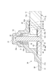
- FIG. 1 It is a perspective view which shows the access door provided in the main wing of the aircraft in this Embodiment. It is a perspective developed view of an access door. It is sectional drawing which shows the attachment structure of the access door with respect to the wing
- FIG. 1 is a perspective view of an access door (blocking member) 20 provided on a main wing 10 constituting a fuselage of an aircraft to which an opening blocking member according to the present embodiment is applied, as viewed from the inside of the main wing 10.
- the access door 20 is provided on a wing surface panel (panel) 11 that forms the upper or lower surface of the main wing 10 so that maintenance personnel can enter and leave the fuel tank provided in the internal space of the main wing 10. .
- the blade surface panel 11 is formed with an opening 12 that communicates the inside and outside of the main wing 10.
- the opening 12 may have an appropriate shape such as an ellipse, an ellipse, or a circle.
- the access door 20 includes a door main body (closing member main body) 30 disposed on the inner space side of the main wing 10 with respect to the opening 12, a clamp ring (clamp member) 40 disposed on the outer side of the main wing 10, and these It is comprised from the fastener member (fastener) 50 which fastens the door main body 30 and the clamp ring 40. As shown in FIG.
- the door body 30 has a larger outer dimension than the opening 12.
- the door body 30 has an outer surface 31 a that forms a continuous surface with the wing outer surface 11 a of the wing surface panel 11, a plate portion 31 having an outer dimension smaller than the opening 12, and an outer peripheral portion of the plate portion 31. And a flange portion 32 that abuts the periphery of the opening 12 on the inner space side of the main wing 10.
- the flange portion 32 is a receiving surface 32a that hits the periphery of the opening 12 on the inner space side of the main wing 10, and a receiving portion of the fastener member 50 that is formed at a portion facing the clamp ring 40 inside the contacting surface 32a. Part 33.
- a plurality of receiving portions 33 are provided along the circumferential direction of the outer peripheral portion of the door main body 30 corresponding to the installation positions of the fastener members 50.
- Each receiving portion 33 protrudes toward the inner space side of the main wing 10, and a recessed portion 33 a that opens to the side facing the clamp ring 40 is formed.
- the clamp ring 40 has a ring shape having an outer diameter larger than the inner diameter dimension of the opening 12 and an inner diameter smaller than the inner diameter dimension of the opening 12.
- the clamp ring 40 has a quadrangular cross section, and an outer surface 40a that is the outer side of the main wing 10 forms a surface that is continuous with the outer surface 11a of the wing surface panel 11 and faces the receiving portion 33 of the door body 30. 40b is formed in parallel with the outer surface 40a.
- a through hole 41 that penetrates the outer surface 40 a and the opposing surface 40 b is formed at a position corresponding to the receiving portion 33 of the door body 30.
- the shaft portion 52 a of the fastener member 50 is inserted into each through hole 41.
- a tapered seat surface 42 that accommodates the head portion 52 c of the fastener member 50 is formed on the side facing the outer surface of the main wing 10.
- a contact surface 34 is formed on the outer peripheral portion of the plate portion 31 to hit the inner peripheral side of the facing surface 40b of the clamp ring 40. Further, a contact surface 14 is formed on the inner peripheral portion of the opening 12 of the wing surface panel 11 and hits the outer peripheral side of the opposing surface 40b of the clamp ring 40. The clamp ring 40 is attached so as to abut against the contact surfaces 14 and 34 via the gasket 43.
- Such an access door 20 sandwiches the inner peripheral edge portion of the opening portion 12 between the abutting surface 32a of the flange portion 32 of the door body 30 and the facing surface 40b of the clamp ring 40 when the opening portion 12 is closed. . Then, the fastener body 52 of the fastener member 50 is inserted into the through hole 41 of the clamp ring 40 from the outside of the main wing 10, and the shaft body 52 a is screwed into the nut 51, whereby the door body 30 and the clamp ring 40 are fastened. .
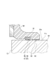
- a ring groove 60 that is continuous in the circumferential direction of the door body 30 is formed on the abutting surface 32 a of the flange portion 32 of the door body 30.
- a ring-shaped fuel seal material (seal material) 61 made of a rubber-based material is fitted in the ring groove 60.
- the fuel seal material 61 is interposed between the flange portion 32 and the blade inner surface 11b of the blade panel 11, thereby preventing fuel leakage.
- an annular first insulator having a predetermined thickness is formed between the annular outer peripheral flat portion 62 located on the inner peripheral side of the ring groove 60 and the blade inner surface 11b of the blade surface panel 11.
- first spacer 63 is sandwiched.
- the first insulator 63 is made of, for example, phenolic resin, and is bonded to the outer peripheral flat surface portion 62 with an adhesive.
- a second annular ring having a predetermined thickness is formed between the annular inner peripheral plane portion 64 located on the outer peripheral side of the ring groove 60 and the blade inner surface 11b of the blade surface panel 11.
- An insulator (second spacer) 65 is provided.
- the second insulator 65 is made of, for example, a glass fiber reinforced resin, and is bonded to the inner peripheral plane portion 64 with an adhesive.
- the first insulator 63 is provided in the normal state.
- the insulator 63 is sandwiched between the outer peripheral flat portion 62 and the blade inner surface 11b, thereby preventing the door body 30 and the blade inner surface 11b from being in direct electrical contact.
- the 2nd insulator 65 is inserted
- the second insulator 65 can prevent the door body 30 and the blade inner surface 11b from being in direct electrical contact, and even when the first insulator 63 falls off, an arc or spark is generated during a lightning strike. Can be prevented.
- the inner peripheral plane portion 64 in a state where the first insulator 63 is tightly sandwiched between the outer peripheral plane portion 62 and the blade inner surface 11 b by the fastening force of the fastener member 50.
- the second insulator 65 bonded to the blade is opposed to the blade inner surface 11b with a predetermined clearance C therebetween.
- the second insulator 65 is not in contact with the blade inner surface 11b, and the fastening force of the fastener member 50 is the second insulation even if the door body 30 is repeatedly attached to and detached from the opening 12.
- the second insulator 65 can be prevented from peeling off without acting on the body 65.
- the first insulator 63 and the second insulator 65 are formed of different materials, it is possible to avoid the risk of peeling due to the same factor.
- the outer peripheral plane portion 62 is formed at a position farther from the blade inner surface 11b than the tip surface 65a of the second insulator 65 attached to the inner peripheral plane portion 64.
- a predetermined clearance C2 is secured between the outer peripheral plane portion 62 and the blade inner surface 11b so as to prevent arcs and sparks during lightning strikes.
- the second insulator 65 is predetermined between the blade inner surface 11b and the first insulator 63 tightly sandwiched between the outer peripheral flat surface portion 62 and the blade inner surface 11b.
- the present invention is not limited to this. That is, as shown in FIG. 6, in a state where the first insulator 63 is tightly sandwiched between the outer peripheral plane portion 62 and the blade inner surface 11b, the second insulator 65 is connected to the inner peripheral plane portion 64 and the blade inner surface. It may be sandwiched between the surface 11b.
- the second insulator 65 is formed of a softer material than the first insulator 63, and when the fastening force by the fastener member 50 is applied, the door body 30 and the blade inner surface 11b are pressed against each other. It is preferable that the force is mainly borne by the first insulator 63.
- the fuel seal material 61 can be configured to function as the second insulator 65.
- the fuel seal material 61 is provided with a core material 68 made of, for example, PEEK having sufficient strength to withstand the fastening force of the fastener member 50, and a core material provided on the outer periphery thereof. It is preferable to provide a seal portion 69 made of a rubber material softer than the material 68.
- the cross-sectional area, density, and the like may be set so that the door body 30 and the blade inner surface 11b are not in direct electrical contact.
- the door main body 30 and the clamp ring 40 have been described.
- the fastening structure, the shape of the door main body 30 and the clamp ring 40, and the like are not intended to be limited to those described above. Any other configuration can be used as appropriate.
- the materials of the first insulator 63 and the second insulator 65 are not limited to those described above.
- any material may be used as long as it satisfies the required conditions such as insulation, heat resistance, oil resistance, adhesion, and the like, including polyimide, PET, ethylene resin, and the like.
- the configuration described in the above embodiment can be selected or changed to another configuration as appropriate.
Landscapes
- Engineering & Computer Science (AREA)
- Mechanical Engineering (AREA)
- Aviation & Aerospace Engineering (AREA)
- Special Wing (AREA)
- Gasket Seals (AREA)
- Connection Of Plates (AREA)
- Insulators (AREA)
Abstract
Description
そして、燃料タンクの内部の点検・保守作業等を行うため、主翼の表面に、開口部が形成されている。通常時においては、この開口部はアクセスドアにより閉塞され、点検・保守作業等を行うときには、アクセスドアを開放する。
ドア本体、クランプリングは、それぞれ開口部よりも大きな外形寸法を有している。ドア本体の外周部と、クランプリングの外周部とで、開口部の周縁部を挟み込んだ状態で、ドア本体とクランプリングとがファスナ部材等により締結されることで、ドア本体により開口部を閉塞する。
このため、従来より、主翼の内部側に配置されるドア本体の外周部と、主翼側の開口部との間に、リング状の絶縁材を挟みこむ構成が採用されている(例えば、特許文献1~3参照。)。このような構成では、絶縁材を挟み込むことによって、ドア本体の外周部と主翼側とが電気的に直接接触しないようにして、この部分から燃料タンク内にアーク、スパークが生じるのを防ぐ。
本発明は、このような技術的課題に基づいてなされたもので、耐雷機能をより確実に維持することのできる開口部の閉塞部材を提供することを目的とする。
これにより、第一スペーサが脱落したときには、第二スペーサが閉塞部材本体の外周部と対向面との間に挟み込まれるので、閉塞部材本体とパネルとの間にクリアランスを確保することができる。
このような第一スペーサ、第二スペーサは、閉塞部材本体の周方向に間隔を隔てて複数を設けるようにしても良いが、第一スペーサおよび第二スペーサの少なくとも一方は、閉塞部材本体の周方向に連続するリング状とするのが好ましい。
さらに、閉塞部材本体の外周部において、第一スペーサと対向する部分は、第一スペーサが脱落して第二スペーサが閉塞部材本体の外周部と対向面との間に挟み込まれた状態では、対向面との間にクリアランスを有しているよう形成する。これにより、閉塞部材本体とパネルとの間で落雷時にアーク、スパークが発生するのを確実に防止できる。
この場合、シール材は、押しつぶされて閉塞部材本体とパネルとの間のクリアランスが確保できなくなるのを防ぐため、芯材と、芯材よりも柔軟な材料で形成されたシール部を有するのが好ましい。
このような開口部は、航空機であればいかなる箇所、用途であっても良いが、機体を構成する主翼に設けられ、主翼内に収容された燃料タンクへの出入り口である場合に特に有効である。
図1は、本実施の形態における開口部の閉塞部材を適用した航空機の機体を構成する主翼10に設けられたアクセスドア(閉塞部材)20を、主翼10の内側から見た斜視図である。
アクセスドア20は、主翼10の内部空間に設けられた燃料タンク内に整備担当員が出入りするため、主翼10の上側または下側の表面を形成する翼面パネル(パネル)11に設けられている。
各受け部33は、主翼10の内部空間側に向けて突出しており、クランプリング40に対向する側に開口した凹部33aが形成されている。そして、凹部33a内に、ファスナ部材50を構成するナット51をリテーナ53によって保持するとともに、ファスナ部材50を構成するファスナ本体52の軸部52aを収容する。
クランプリング40には、外表面40a、対向面40bを貫通する貫通孔41が、ドア本体30の受け部33に対応した位置に形成されている。各貫通孔41には、ファスナ部材50の軸部52aが挿通される。各貫通孔41において、主翼10の外表面に対向する側に、ファスナ部材50の頭部52cを収容するテーパ状の座面42が形成されている。
また、翼面パネル11の開口部12の内周部には、クランプリング40の対向面40bの外周側に当たる当たり面14が形成されている。
そして、クランプリング40は、ガスケット43を介して、当たり面14、34に突き当たるよう取り付けられる。
突き当たり面32aにおいて、リング溝60の内周側に位置する環状の外周平面部62と翼面パネル11の翼内表面11bとの間には、環状で所定の厚さを有した第一絶縁体(第一スペーサ)63が挟み込まれている。ここで、第一絶縁体63は、例えばフェノリック樹脂からなり、外周平面部62に接着剤により接着されている。
また、突き当たり面32aにおいて、リング溝60の外周側に位置する環状の内周平面部64と翼面パネル11の翼内表面11bとの間には、環状で所定の厚さを有した第二絶縁体(第二スペーサ)65が設けられている。ここで、第二絶縁体65は、例えばガラスファイバー強化樹脂からなり、内周平面部64に接着剤により接着されている。
また、第一絶縁体63と第二絶縁体65は異なる材料で形成されているため、同一の要因で剥がれが生じるリスクを回避することができる。
また、第一絶縁体63、第二絶縁体65の材質は上記に挙げたものに限るものではない。上記以外にも、ポリイミド、PET、エチレン系樹脂等をはじめとして、絶縁性、耐熱性、耐油性、接着性等所要の条件を満たす材質であればいかなるものを用いても良い。
これ以外にも、本発明の主旨を逸脱しない限り、上記実施の形態で挙げた構成を取捨選択したり、他の構成に適宜変更することが可能である。
Claims (9)
- 航空機の機体の外表面を構成するパネルに形成された開口部の閉塞部材であって、
前記閉塞部材は、
前記パネルの一面側に配置され、前記開口部よりも大きな外径寸法を有して前記開口部を塞ぐ閉塞部材本体と、
前記パネルの他面側に配置され、前記開口部よりも大きな外径寸法を有したリング状のクランプ部材と、
前記閉塞部材本体の外周部と前記クランプ部材の外周部とで前記パネルを挟み込んだ状態で、前記閉塞部材本体と前記クランプ部材とを締結するファスナと、を備え、
前記閉塞部材本体の外周部と、前記開口部の周囲において前記外周部に対向する対向面との間に介在する第一スペーサおよび第二スペーサを備え、
前記第一スペーサは、前記閉塞部材本体で前記開口部を塞いだ状態で前記閉塞部材本体の前記外周部と前記対向面との間に挟み込まれ、
前記第二スペーサは、少なくとも前記第一スペーサが脱落した状態のときに、前記閉塞部材本体の前記外周部と前記対向面との間に挟み込まれることを特徴とする開口部の閉塞部材。 - 前記第二スペーサは、前記第一スペーサが前記閉塞部材本体の前記外周部と前記対向面との間に挟み込まれた状態では、前記閉塞部材本体の前記外周部と前記対向面との間にクリアランスを有していることを特徴とする請求項1に記載の開口部の閉塞部材。
- 前記閉塞部材本体の前記外周部において、前記第一スペーサと対向する部分は、前記第一スペーサが脱落して前記第二スペーサが前記閉塞部材本体の前記外周部と前記対向面との間に挟み込まれた状態では、前記対向面との間にクリアランスを隔てるよう形成されていることを特徴とする請求項1または2に記載の開口部の閉塞部材。
- 前記第一スペーサと前記第二スペーサは互いに異なる材料で形成されていることを特徴とする請求項1から3のいずれか一項に記載の開口部の閉塞部材。
- 前記第二スペーサは、前記第一スペーサよりも柔らかい材料で形成され、かつ、前記第一スペーサが前記閉塞部材本体の前記外周部と前記対向面との間に挟み込まれた状態で、前記閉塞部材本体の前記外周部と前記対向面との間に挟み込まれていることを特徴とする請求項1に記載の開口部の閉塞部材。
- 前記閉塞部材本体の周方向に連続するリング状で、前記閉塞部材本体の前記外周面と前記対向面との間における液密性を確保するシール材が設けられ、
前記シール材が前記第二スペーサとして機能することを特徴とする請求項5に記載の開口部の閉塞部材。 - 前記シール材が、芯材と、前記芯材よりも柔軟な材料で形成されたシール部を有することを特徴とする請求項6に記載の開口部の閉塞部材。
- 前記第一スペーサおよび前記第二スペーサの少なくとも一方が前記閉塞部材本体の周方向に連続するリング状であることを特徴とする請求項1から7のいずれか一項に記載の開口部の閉塞部材。
- 前記開口部が、前記機体を構成する主翼に設けられ、前記主翼内に収容された燃料タンクへの出入り口であることを特徴とする請求項1から8のいずれか一項に記載の開口部の閉塞部材。
Priority Applications (4)
| Application Number | Priority Date | Filing Date | Title |
|---|---|---|---|
| EP11783230.3A EP2572977B1 (en) | 2010-05-17 | 2011-05-11 | Occluding member for opening |
| BR112012015834-1A BR112012015834B1 (pt) | 2010-05-17 | 2011-05-11 | elemento de fecho para uma abertura formada em um painel |
| US13/511,496 US8684216B2 (en) | 2010-05-17 | 2011-05-11 | Closing member for opening |
| CA2781961A CA2781961C (en) | 2010-05-17 | 2011-05-11 | Closing member for opening |
Applications Claiming Priority (2)
| Application Number | Priority Date | Filing Date | Title |
|---|---|---|---|
| JP2010-112782 | 2010-05-17 | ||
| JP2010112782A JP5529624B2 (ja) | 2010-05-17 | 2010-05-17 | 開口部の閉塞部材 |
Publications (1)
| Publication Number | Publication Date |
|---|---|
| WO2011145291A1 true WO2011145291A1 (ja) | 2011-11-24 |
Family
ID=44991413
Family Applications (1)
| Application Number | Title | Priority Date | Filing Date |
|---|---|---|---|
| PCT/JP2011/002607 Ceased WO2011145291A1 (ja) | 2010-05-17 | 2011-05-11 | 開口部の閉塞部材 |
Country Status (6)
| Country | Link |
|---|---|
| US (1) | US8684216B2 (ja) |
| EP (2) | EP2572977B1 (ja) |
| JP (1) | JP5529624B2 (ja) |
| BR (1) | BR112012015834B1 (ja) |
| CA (1) | CA2781961C (ja) |
| WO (1) | WO2011145291A1 (ja) |
Cited By (1)
| Publication number | Priority date | Publication date | Assignee | Title |
|---|---|---|---|---|
| WO2015037660A1 (ja) | 2013-09-11 | 2015-03-19 | 三菱重工業株式会社 | 燃料タンク用ダム、及び閉塞方法 |
Families Citing this family (15)
| Publication number | Priority date | Publication date | Assignee | Title |
|---|---|---|---|---|
| WO2013109305A1 (en) | 2011-08-19 | 2013-07-25 | Aerovironment, Inc. | Water-tight compartment with removable hatch and two-sided gel seal for multiple conduit access |
| JP5875377B2 (ja) * | 2012-01-13 | 2016-03-02 | 三菱航空機株式会社 | 航空機の機体 |
| US9016631B2 (en) * | 2012-04-09 | 2015-04-28 | R4 Integration, Inc. | Multi-purpose hatch system |
| EP2842865B1 (en) * | 2013-08-28 | 2019-12-18 | Airbus Operations GmbH | Window panel for an airframe and method of producing same |
| US9517830B2 (en) * | 2014-03-18 | 2016-12-13 | The Boeing Company | Seal design for vehicle and structure application |
| US9718533B2 (en) * | 2014-07-01 | 2017-08-01 | Textron Innovations, Inc. | Fuel tank access door systems and methods |
| JP6382019B2 (ja) * | 2014-08-08 | 2018-08-29 | 三菱航空機株式会社 | 航空機 |
| JP6674740B2 (ja) * | 2015-02-10 | 2020-04-01 | 三菱航空機株式会社 | バーストディスク装置および航空機 |
| US10112695B2 (en) * | 2015-08-20 | 2018-10-30 | Georgian Aerospace Llc | Receptacle, payload assembly and related methods for an aircraft |
| FR3043063B1 (fr) * | 2015-10-28 | 2017-11-24 | Aviacomp | Porte d'acces au reservoir de carburant ou a une zone seche d'un aeronef |
| FR3043062B1 (fr) * | 2015-10-28 | 2017-11-24 | Aviacomp | Porte d'acces au reservoir de carburant ou a une zone seche d'un aeronef |
| US10183735B2 (en) | 2016-02-01 | 2019-01-22 | The Boeing Company | Window frame assembly for aircraft |
| US11352063B2 (en) * | 2018-08-30 | 2022-06-07 | Clark Equipment Company | Frame access aperture |
| US11794124B2 (en) * | 2018-10-02 | 2023-10-24 | Snap Ships LLC | Connection systems for toy construction pieces, toy construction pieces including the same, and toy construction kits including the same |
| GB2600409B (en) * | 2020-10-27 | 2022-11-02 | Airbus Operations Ltd | Fuel tank assemblies |
Citations (4)
| Publication number | Priority date | Publication date | Assignee | Title |
|---|---|---|---|---|
| US4530443A (en) | 1983-11-10 | 1985-07-23 | The Boeing Company | Unitary access panel for aircraft fuel tanks |
| US4579248A (en) | 1983-11-10 | 1986-04-01 | The Boeing Company | Access panel assembly for aircraft fuel tank |
| US20070207421A1 (en) * | 2006-02-23 | 2007-09-06 | Heeter Russell J | Method and system for electrical bonding of fuel tank penetrations |
| JP2009519479A (ja) * | 2005-12-13 | 2009-05-14 | バリオプテイツク | 気密エレクトロウェッティング装置 |
Family Cites Families (11)
| Publication number | Priority date | Publication date | Assignee | Title |
|---|---|---|---|---|
| US4345739A (en) * | 1980-08-07 | 1982-08-24 | Barton Valve Company | Flanged sealing ring |
| US4428867A (en) * | 1981-11-02 | 1984-01-31 | Lockheed Corporation | Electrically conductive structural adhesive |
| JPS60131395A (ja) | 1983-12-19 | 1985-07-13 | Tech Res & Dev Inst Of Japan Def Agency | 掃海索展開装置 |
| US4597583A (en) * | 1985-07-08 | 1986-07-01 | Felt Products Mfg. Co. | Gasket assembly for sealing covers to automotive engines |
| JPH0533600Y2 (ja) * | 1985-08-30 | 1993-08-26 | ||
| JP2001004031A (ja) * | 1999-04-21 | 2001-01-09 | Bridgestone Corp | ガスケット及びその製造方法 |
| US20070062841A1 (en) * | 2002-12-06 | 2007-03-22 | Kazuhiro Nakamura | Cover body mounting structure of resin container |
| US8091831B2 (en) * | 2006-11-28 | 2012-01-10 | Airbus Deutschland Gmbh | Aircraft with door seal arrangement |
| ES2347507B1 (es) * | 2007-12-27 | 2011-08-17 | Airbus Operations, S.L. | Boca de acceso de aeronave optimizada. |
| US8443575B1 (en) * | 2009-10-27 | 2013-05-21 | The Boeing Company | Composite access door |
| ES2404456B1 (es) * | 2011-01-26 | 2014-04-29 | Airbus Operations S.L. | Montaje de una boca de acceso en el revestimiento inferior de un ala de aeronave realizada con un material compuesto. |
-
2010
- 2010-05-17 JP JP2010112782A patent/JP5529624B2/ja not_active Expired - Fee Related
-
2011
- 2011-05-11 EP EP11783230.3A patent/EP2572977B1/en not_active Not-in-force
- 2011-05-11 US US13/511,496 patent/US8684216B2/en active Active
- 2011-05-11 WO PCT/JP2011/002607 patent/WO2011145291A1/ja not_active Ceased
- 2011-05-11 EP EP15180358.2A patent/EP2962933B1/en not_active Not-in-force
- 2011-05-11 CA CA2781961A patent/CA2781961C/en active Active
- 2011-05-11 BR BR112012015834-1A patent/BR112012015834B1/pt not_active IP Right Cessation
Patent Citations (5)
| Publication number | Priority date | Publication date | Assignee | Title |
|---|---|---|---|---|
| US4530443A (en) | 1983-11-10 | 1985-07-23 | The Boeing Company | Unitary access panel for aircraft fuel tanks |
| US4579248A (en) | 1983-11-10 | 1986-04-01 | The Boeing Company | Access panel assembly for aircraft fuel tank |
| JP2009519479A (ja) * | 2005-12-13 | 2009-05-14 | バリオプテイツク | 気密エレクトロウェッティング装置 |
| US7576922B2 (en) | 2005-12-13 | 2009-08-18 | Varioptic S.A. | Hermetic electrowetting device |
| US20070207421A1 (en) * | 2006-02-23 | 2007-09-06 | Heeter Russell J | Method and system for electrical bonding of fuel tank penetrations |
Non-Patent Citations (1)
| Title |
|---|
| See also references of EP2572977A4 |
Cited By (2)
| Publication number | Priority date | Publication date | Assignee | Title |
|---|---|---|---|---|
| WO2015037660A1 (ja) | 2013-09-11 | 2015-03-19 | 三菱重工業株式会社 | 燃料タンク用ダム、及び閉塞方法 |
| US9815562B2 (en) | 2013-09-11 | 2017-11-14 | Mitsubishi Heavy Industries, Ltd. | Fuel tank dam |
Also Published As
| Publication number | Publication date |
|---|---|
| EP2572977A4 (en) | 2014-07-30 |
| BR112012015834A2 (pt) | 2016-06-14 |
| EP2962933B1 (en) | 2016-12-07 |
| CA2781961C (en) | 2014-09-02 |
| EP2572977B1 (en) | 2016-04-27 |
| BR112012015834B1 (pt) | 2020-07-07 |
| JP2011240754A (ja) | 2011-12-01 |
| JP5529624B2 (ja) | 2014-06-25 |
| US8684216B2 (en) | 2014-04-01 |
| CA2781961A1 (en) | 2011-11-24 |
| EP2962933A1 (en) | 2016-01-06 |
| US20130062352A1 (en) | 2013-03-14 |
| EP2572977A1 (en) | 2013-03-27 |
Similar Documents
| Publication | Publication Date | Title |
|---|---|---|
| JP5529624B2 (ja) | 開口部の閉塞部材 | |
| EP2441678B1 (en) | Lightning strike protection in aircraft | |
| JP5822493B2 (ja) | 耐雷ファスナ、航空機組立品、航空機組立部品の製造方法 | |
| RU2448875C2 (ru) | Узел летательного аппарата | |
| US9080694B2 (en) | Bulkhead fitting assembly | |
| EP1826120B1 (en) | Method and system for electrical bonding of fuel tank penetrations | |
| US20180156130A1 (en) | Aircraft seal structure and aircraft | |
| JP5478289B2 (ja) | 開口部の閉塞部材、航空機 | |
| JP2013144494A (ja) | 航空機の機体 | |
| JP5378260B2 (ja) | 開口部の閉塞部材、航空機 | |
| US9309003B2 (en) | Access door for possible use with a helicopter fuel tank | |
| FR3088617A1 (fr) | Paroi pare-feu comportant un dispositif de raccordement d’une canalisation ainsi qu’un bouclier thermique et aeronef comprenant au moins une telle paroi pare-feu | |
| US20090194946A1 (en) | Sealing for ball-and-socket joints and use thereof |
Legal Events
| Date | Code | Title | Description |
|---|---|---|---|
| 121 | Ep: the epo has been informed by wipo that ep was designated in this application |
Ref document number: 11783230 Country of ref document: EP Kind code of ref document: A1 |
|
| WWE | Wipo information: entry into national phase |
Ref document number: 13511496 Country of ref document: US |
|
| ENP | Entry into the national phase |
Ref document number: 2781961 Country of ref document: CA |
|
| WWE | Wipo information: entry into national phase |
Ref document number: 2011783230 Country of ref document: EP |
|
| REG | Reference to national code |
Ref country code: BR Ref legal event code: B01A Ref document number: 112012015834 Country of ref document: BR |
|
| NENP | Non-entry into the national phase |
Ref country code: DE |
|
| ENP | Entry into the national phase |
Ref document number: 112012015834 Country of ref document: BR Kind code of ref document: A2 Effective date: 20120626 |