WO2011145319A1 - 形状測定装置及び形状測定方法 - Google Patents
形状測定装置及び形状測定方法 Download PDFInfo
- Publication number
- WO2011145319A1 WO2011145319A1 PCT/JP2011/002703 JP2011002703W WO2011145319A1 WO 2011145319 A1 WO2011145319 A1 WO 2011145319A1 JP 2011002703 W JP2011002703 W JP 2011002703W WO 2011145319 A1 WO2011145319 A1 WO 2011145319A1
- Authority
- WO
- WIPO (PCT)
- Prior art keywords
- shape measuring
- sets
- measurement object
- value
- data set
- Prior art date
- Legal status (The legal status is an assumption and is not a legal conclusion. Google has not performed a legal analysis and makes no representation as to the accuracy of the status listed.)
- Ceased
Links
Images


Classifications
-
- G—PHYSICS
- G01—MEASURING; TESTING
- G01B—MEASURING LENGTH, THICKNESS OR SIMILAR LINEAR DIMENSIONS; MEASURING ANGLES; MEASURING AREAS; MEASURING IRREGULARITIES OF SURFACES OR CONTOURS
- G01B11/00—Measuring arrangements characterised by the use of optical techniques
- G01B11/24—Measuring arrangements characterised by the use of optical techniques for measuring contours or curvatures
- G01B11/25—Measuring arrangements characterised by the use of optical techniques for measuring contours or curvatures by projecting a pattern, e.g. one or more lines, moiré fringes on the object
- G01B11/2513—Measuring arrangements characterised by the use of optical techniques for measuring contours or curvatures by projecting a pattern, e.g. one or more lines, moiré fringes on the object with several lines being projected in more than one direction, e.g. grids, patterns
-
- G—PHYSICS
- G01—MEASURING; TESTING
- G01B—MEASURING LENGTH, THICKNESS OR SIMILAR LINEAR DIMENSIONS; MEASURING ANGLES; MEASURING AREAS; MEASURING IRREGULARITIES OF SURFACES OR CONTOURS
- G01B11/00—Measuring arrangements characterised by the use of optical techniques
- G01B11/02—Measuring arrangements characterised by the use of optical techniques for measuring length, width or thickness
- G01B11/06—Measuring arrangements characterised by the use of optical techniques for measuring length, width or thickness for measuring thickness ; e.g. of sheet material
- G01B11/0608—Height gauges
-
- H—ELECTRICITY
- H04—ELECTRIC COMMUNICATION TECHNIQUE
- H04N—PICTORIAL COMMUNICATION, e.g. TELEVISION
- H04N7/00—Television systems
- H04N7/18—Closed-circuit television [CCTV] systems, i.e. systems in which the video signal is not broadcast
Definitions
- the present invention relates to a pattern projection type shape measuring apparatus and a shape measuring method by a phase shift method.
- a pattern projection type three-dimensional shape measuring apparatus using a phase shift method As a method for measuring the surface shape (three-dimensional shape) of a measurement object in a non-contact manner, a pattern projection type three-dimensional shape measuring apparatus using a phase shift method is known.
- a fringe pattern having a sinusoidal intensity distribution is projected onto the measurement object, and the measurement object is repeatedly imaged while the phase of the fringe pattern is changed at a constant pitch, and thereby obtained.
- the phase distribution (phase image) of the stripes deformed according to the surface shape of the measurement object is obtained, and the phase image is unwrapped (phase connection) ) And then converted into a height distribution (height image) of the measurement object.
- the three-dimensional shape measuring apparatus disclosed in Patent Document 1 acquires luminance change data under two types of imaging conditions with different amounts of projection light and prevents two types of luminance change data in order to prevent measurement errors caused by saturated pixels.
- the brightness change data having a low contrast value is excluded from the calculation target.
- an object of the present invention is to provide a shape measuring apparatus and a shape measuring method capable of reliably suppressing the influence of inappropriate luminance data on the measurement result.
- a projection unit that sequentially projects a plurality of types of patterns having a common repetitive structure and different phases onto a measurement object, and each of the plurality of types of patterns includes the An imaging unit that captures an image data set by capturing the measurement object every time it is projected onto the measurement object, and a data set related to the same region on the measurement object from the acquired image data set.
- the selection unit that selects all the data in the set within the effective luminance range as an appropriate data set, and the acquisition of the appropriate data in the measurement object based on the selected appropriate data set.
- a shape calculation unit that obtains the shape of the original region.
- the shape measurement method of the present invention includes a projection procedure for sequentially projecting a plurality of types of patterns having a common repetitive structure and different phases onto a measurement target, and each of the plurality of types of patterns is the measurement target.
- a shape measuring device and a shape measuring method capable of reliably suppressing the influence of inappropriate luminance data on the measurement result are realized.
- FIG. 1 is a perspective view showing a mechanical configuration of the three-dimensional shape measuring apparatus of the present embodiment.
- the three-dimensional shape measuring apparatus includes a stage 12 on which a measurement object 11 such as an industrial product or a part is placed, and a projection unit 13 and an imaging unit 14 fixed to each other.
- the optical axis of the imaging unit 14 is perpendicular to the reference plane of the stage 12. It is possible to make the optical axis of the projection unit 13 vertical instead of making the optical axis of the imaging unit 14 vertical, but here it is assumed that the optical axis of the imaging unit 14 is vertical.
- the stage 12 has a ⁇ stage 12 ⁇ that rotates the measurement object 11 around an axis parallel to the optical axis of the imaging unit 14, and a measurement object toward a predetermined direction (X direction) perpendicular to the optical axis of the imaging unit 14.
- X stage 12X that shifts 11
- Y stage 12Y that shifts measurement object 11 in a predetermined direction (Y direction) perpendicular to both the rotational axis of ⁇ stage 12 ⁇ and the X direction.
- the projection unit 13 is an optical system that illuminates a partial region (illumination region) on the stage 12 from an oblique direction with respect to the optical axis of the imaging unit 14, and includes an illumination element 22, a pattern formation unit 23, The projection optical system 24 is arranged in this order. It is assumed that the size of the measurement object 11 of the present embodiment is small enough to fit the entire measurement object 11 in the illumination area of the projection unit 13.
- the pattern forming unit 23 of the projection unit 13 is a panel (liquid crystal display element or the like) having a variable transmittance distribution. By displaying a striped pattern (sine lattice pattern) on the panel, the projection unit 13 changes to the illumination region.
- the cross-sectional intensity distribution of the illuminating light beam going is made sinusoidal.
- the repetitive direction of the grid-like light and darkness of the sine lattice pattern displayed on the pattern forming unit 23 is perpendicular to the plane on which both the optical axis of the projection unit 13 and the optical axis of the imaging unit 14 exist.
- the reference point located in the vicinity of the center on the display surface of the pattern forming unit 23 is optically conjugate with respect to the intersection of the optical axis of the imaging unit 14 and the optical axis of the projection unit 13, and thereby sine.
- the projection destination of the lattice pattern is set on the surface of the measurement object 11 (hereinafter referred to as “test surface”) arranged in the illumination area of the stage 12.
- test surface the surface of the measurement object 11
- the reference point of the pattern forming unit 23 and the reference point of the stage 12 do not have to be completely conjugate as long as a sine lattice pattern can be projected on the surface to be measured.
- the imaging unit 14 is an optical system that detects an image (luminance distribution) of an illumination area on the stage 12.
- the imaging optical system 25 forms an image of reflected light generated in the illumination area, and the imaging optical system 25.
- An image pickup element 26 that picks up an image formed by the image pickup device and acquires the image is sequentially arranged.
- the reference point located in the vicinity of the center on the imaging surface of the imaging device 26 is optically conjugate with respect to the intersection of the optical axis of the imaging unit 14 and the optical axis of the projection unit 13. In addition, it is possible to obtain an image of the measurement object 11 (image of the test surface) arranged in the illumination area by the projection unit 13.
- the intersection of the optical axis of the imaging unit 14 and the optical axis of the projection unit 13 and the reference point of the imaging element 26 are completely conjugate. You don't have to be in a relationship.
- this image is referred to as a “stripe image”.
- the acquisition of the fringe image is repeated while shifting the phase of the sine grating pattern without changing the period of the sine grating pattern, information for making the surface shape data D of the test surface known is gathered.
- the test surface may be made of a highly reflective material such as metal and include various portions with different inclination angles.
- an extremely bright portion and an extremely dark portion are mixed on the test surface.
- the extremely bright part is a part having an inclination angle that reflects most of the illumination light (mainly specularly reflected light) incident from the projection unit 13 side toward the imaging unit 14.
- the dark portion is a portion having an inclination angle that reflects most of the illumination light (mainly specularly reflected light) emitted from the projection unit 13 toward the direction away from the imaging unit 14.
- FIG. 2 is an overall configuration diagram of the three-dimensional shape measuring apparatus.
- a main light source 21 that is a light source of the projection unit 13 is connected to the projection unit 13. Since the main light source 21 is used for pattern projection type surface shape measurement, for example, a general light source such as an LED, a halogen lamp, a metal halide lamp, or a laser light source can be applied.
- the light emitted from the main light source 21 is introduced into the illumination element 22 through the optical fiber 21 '.
- a small light source such as an LED may be disposed at a position indicated by reference numeral 22 in FIG. 1 without using the optical fiber.
- the main light source 21, the pattern forming unit 23 of the projection unit 13, and the image sensor 26 of the imaging unit 14 are each connected to the control unit 101 of the computer 100.
- the control unit 101 turns on / off the main light source 21, the light emission intensity of the main light source 21, the phase of the sine lattice pattern displayed on the pattern forming unit 23, the image acquisition timing by the image sensor 26, and the image by the image sensor 26.
- the charge accumulation time at the time of acquisition (hereinafter referred to as “shutter speed”), the coordinates of the stage 12, and the like are controlled.
- the control unit 101 can also set the pattern displayed on the pattern forming unit 23 to a uniform pattern.
- the computer 100 includes a CPU 15 that controls the entire three-dimensional shape measuring apparatus, a storage unit 16, a monitor 17, and an input unit 18.
- the storage unit 16 stores an operation program for the CPU 15 in advance, and the CPU 15 operates according to the operation program.
- the CPU 15 drives and controls each unit of the three-dimensional shape measuring apparatus by giving various instructions to the control unit 101.
- various information necessary for the operation of the CPU 15 is stored in the storage unit 16 in advance.
- FIG. 3 is an operation flowchart of the CPU 15 (and the control unit 101) regarding measurement. Hereafter, each step of FIG. 3 is demonstrated in order. It is assumed that the coordinates of the stage 12 have been adjusted to appropriate coordinates at the start of this flow.
- Step S10 The CPU 15 instructs the control unit 101 to perform the pre-measurement.
- the control unit 101 drives each unit of the three-dimensional shape measuring apparatus to perform pre-measurement.
- the control unit 10 sets the pattern to be displayed on the pattern forming unit 23 to a uniform bright pattern (a uniform pattern having the same brightness as the bright portion of the sine lattice pattern), and the image sensor 26 is Drives repeatedly under various shutter speeds.
- the plurality of images acquired by such pre-measurement are sent to the CPU 15 as information indicating variations in the amount of light reaching the imaging unit 14 from the test surface.
- the CPU 15 determines k max measurement conditions by a determination method described later, the CPU 15 provides the control unit 101 with information on the k max measurement conditions and an instruction to start the main measurement.
- parameters other than the shutter speed are common among the k max measurement conditions, and the shutter speed is set to be larger (the exposure amount is larger) as the measurement condition has a smaller condition number k. Further, it is assumed that the final value k max of the condition number k is preset by the user of the apparatus or the manufacturer of the apparatus, and is set to “6” here.
- the shutter speed under the measurement condition with the condition number k is represented as “SS (k)”.
- Step S11 The control unit 101 sets the condition number k to the initial value 1.
- Step S12 The control unit 101 sets the shutter speed of the image sensor 26 to the shutter speed SS (k) corresponding to the current condition number k.
- Step S13 The control unit 101 sets the image number m to the initial value 1.
- Step S14 The control unit 101 sets the phase shift amount of the sine lattice pattern to the shift amount (m ⁇ 1) ⁇ / 2 corresponding to the current image number m.
- Step S15 The control unit 101 turns on the light source device 21 to project a sine lattice pattern having a phase shift amount of (m ⁇ 1) ⁇ / 2 onto the measurement object 11, and the current shutter speed SS (k ) To drive the image sensor 26 to obtain a fringe image I km .
- the acquired fringe image I km is written to the storage unit 16 via the CPU 15.
- Step S16 The control unit 101 determines whether or not the current image number m has reached the final value m max . If it has not reached, the process proceeds to step S17, and if it has reached, the process proceeds to step S18.
- the 4-bucket method is applied to phase calculation described later, and the final value m max of the image number m is set to “4”.
- Step S17 The control unit 101 increments the image number m and then returns to step S14. Therefore, the loop of steps S14 to S17 is repeated, and a total of four striped images (stripe image sets I k1 to I k4 ) are acquired.
- Step S18 The control unit 101 determines whether or not the current condition number k has reached the final value k max . If not, the control unit 101 proceeds to step S19, and if it has reached, the flow ends.
- Step S19 The control unit 101 increments the condition number k, and then returns to step S12. Therefore, the loop of steps S12 to S19 is repeated, and a total of six stripe image sets I 11 to I 14 , I 21 to I 24 , I 31 to I 34 , I 41 to I 44 , I 51 to I 54 , I 61 to I 64 are acquired (see FIG. 5A).
- FIG. 4 is an operation flowchart of the CPU 15 regarding analysis. Hereafter, each step of FIG. 4 is demonstrated in order.
- six striped image sets I 11 to I 14 , I 21 to I 24 , I 31 to I 34 , I 41 to I 44 , I 51 to I 54 , I 61 to I 64 (FIG. 5 (A).) Is already stored in the storage unit 16.
- Step S21 The CPU 15 sets the condition number k to the initial value 1.
- Step S22 The CPU 15 sets the pixel number i to an initial value 1.
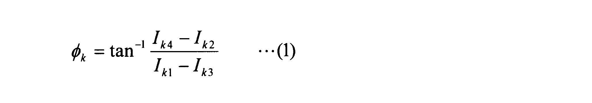
- Step S23 The CPU 15 refers to a pixel set (luminance value set I k1i to I k4i ) corresponding to the current pixel number i among the stripe image sets I k1 to I k4 corresponding to the current condition number k. Then, the CPU 15 calculates the initial phase ⁇ ki by applying the luminance value sets I k1i to I k4i to the equation (1) of the 4-bucket method. Further, the CPU 15 writes the value of the initial phase ⁇ ki into the storage unit 16 as the value of the i-th pixel ⁇ ki of the provisional phase image ⁇ k (see FIG. 5B) corresponding to the current condition number k. .
- Step S24 The CPU 15 determines whether or not the current pixel number i has reached the final value i max . If not, the process proceeds to step S25, and if it has reached, the process proceeds to step S26. Note that the final value i max of the pixel number i is set to correspond to the number of pixels of the image sensor 26.
- Step S25 The CPU 15 increments the pixel number i and then returns to step S23. Therefore, the loop of steps S23 to S25 is repeated, and all the pixels of the provisional phase image ⁇ k (see FIG. 5B) corresponding to the current condition number k are acquired.
- Step S26 The CPU 15 determines whether or not the current condition number k has reached the final value k max (here, 6). If not, the process proceeds to step S27, and if it has reached, the process proceeds to step S28. .
- Step S27 The CPU 15 increments the condition number k and then returns to step S22. Therefore, the loop of steps S22 to S27 is repeated, and a total of six provisional phase images ⁇ 1 , ⁇ 2 , ⁇ 3 , ⁇ 4 , ⁇ 5 , ⁇ 6 (see FIG. 5B) are acquired.
- Step S28 The CPU 15 sets the pixel number i to the initial value 1.
- Step S29 The CPU 15 sets the condition number k to the initial value 1.
- Step S30 The CPU 15 determines whether or not the pixel (initial phase ⁇ ki ) corresponding to the current pixel number i in the provisional phase image ⁇ k corresponding to the current condition number k has reliability. If it is not reliable, the process proceeds to step S31. If it is reliable, the process proceeds to step S32.
- whether or not the initial phase ⁇ ki has reliability depends on whether or not the luminance value set (luminance value sets I k1i to I k4i ) from which the initial phase ⁇ ki is calculated is appropriate. The determination is made based on whether or not all of the luminance value sets I k1i to I k4i are within the effective luminance range.
- the effective luminance range as shown in FIG. 6, of the total output range of the image sensor 16 (full brightness range I min ⁇ I max), the luminance range as the input-output characteristic of the image sensor 16 is a linear I min It means “ ⁇ I max ”.
- This effective luminance range is measured in advance by the manufacturer of this apparatus and written in advance in the storage unit 16 together with the operation program described above.
- Step S31 The CPU 15 increments the condition number k and then returns to step S30. Therefore, the loop of steps S30 and S31 is repeated until a reliable pixel (initial phase ⁇ ki ) is found.
- Step S32 The CPU 15 sends the value of the initial phase ⁇ ki determined to be reliable in step S30 to the storage unit 16 as the value of the i-th pixel ⁇ i of the definite phase image ⁇ (see FIG. 5C). Write.
- Step S33 The CPU 15 determines whether or not the current pixel number i has reached the final value i max . If not, the process proceeds to step S34, and if it has reached, the process proceeds to step S35.
- Step S34 The CPU 15 increments the pixel number i and then returns to step S29. Therefore, the loop of steps S29 to S34 is repeated, and all the pixels of the definite phase image ⁇ (see FIG. 5C) are acquired.
- Step S35 The CPU 15 reads the definite phase image ⁇ from the storage unit 16, performs unwrap processing (phase connection) for adding the offset distribution ⁇ to the definite phase image ⁇ , and performs the unwrapped phase image ⁇ (see FIG. 7).
- the offset distribution ⁇ is measured separately and stored in the storage unit 16 in advance, or is automatically set by phase jump detection). Further, the CPU 15 converts the unwrapped phase image ⁇ (see FIG. 7) into the height distribution Z (X, Y) (see FIG. 8) of the test surface and displays it on the monitor 17. Further, the CPU 15 stores the height distribution Z (X, Y) in the storage unit 16 as necessary, and ends the flow (description of FIG. 4 above).
- the measuring apparatus repeats the acquisition of the luminance change data (luminance value sets I k1i to I k4i ) of each pixel six times while changing the shutter speed (steps S11 to S19), and the six luminance values.
- the measurement apparatus can perform measurement with high accuracy even if an extremely bright portion and an extremely dark portion are mixed on the surface to be measured.
- the measuring apparatus of the present embodiment stores in advance an effective luminance range (see FIG. 6) that is an output range in which the input / output characteristics of the image sensor 26 are linear, and six luminance value sets I are selected in the selection. 11i ⁇ I 14i, I 21i ⁇ I 24i, I 31i ⁇ I 34i, I 41i ⁇ I 44i, I 51i ⁇ I 54i, the luminance value set that fall within the effective luminance range of I 61i ⁇ I 64i, proper It is considered as a set of brightness values.
- the luminance value set that is considered appropriate in the present embodiment is a luminance value set that falls within the effective luminance range shown in FIG. 6 (within the linear range of input / output characteristics), so the relationship between the buckets during the phase shift. Is accurately reflected.
- the accuracy of the phase calculation can be reliably increased.
- the measurement apparatus sequentially determines whether or not it is appropriate from a brightness value set with a large shutter speed (a large exposure amount), and if there are a plurality of appropriate brightness value sets. Among the plurality of luminance value sets, the one having the largest shutter speed (the largest exposure amount) is selected.
- a luminance value set with a good SN ratio is preferentially used, and the accuracy of phase calculation is further increased.
- FIG. 9 is an operation flowchart of the CPU 15 regarding the analysis of the second embodiment. Hereafter, each step of FIG. 9 is demonstrated in order.
- six striped image sets I 11 to I 14 , I 21 to I 24 , I 31 to I 34 , I 41 to I 44 , I 51 to I 54 , I 61 to I 64 (FIG. 10 (A).) Is already stored in the storage unit 16.
- Step S41 The CPU 15 sets the pixel number i to an initial value 1.
- Step S42 The CPU 15 sets the condition number k to the initial value 1.
- Step S43 The CPU 15 refers to a pixel set (luminance value set I k1i to I k4i ) corresponding to the current pixel number i among the stripe image sets I k1 to I k4 corresponding to the current condition number k. It is determined whether or not these luminance value sets I k1i to I k4i are appropriate. If they are not appropriate, the process proceeds to step S44, and if they are appropriate, the process proceeds to step S45.
- the luminance value sets I k1i to I k4i are appropriate is determined depending on whether or not all of the luminance value sets I k1i to I k4i are within the effective luminance range.
- This effective luminance range is the same as that used in step S30 described above, and is measured in advance by the manufacturer of the apparatus and written in advance in the storage unit 16 together with the operation program described above.
- Step S44 The CPU 15 increments the condition number k and then returns to step S43. Therefore, the loop of steps S43 to S44 is repeated until an appropriate luminance value set is found.
- Step S45 The CPU 15 calculates the initial phase ⁇ ki by applying the luminance value sets I k1i to I k4i determined to be appropriate in step S43 to the equation (1) of the 4-bucket method. Then, the CPU 15 writes the value of the initial phase ⁇ ki into the storage unit 16 as the value of the i-th pixel ⁇ i of the definite phase image ⁇ (see FIG. 10B).
- Step S46 The CPU 15 determines whether or not the current pixel number i has reached the final value i max . If not, the process proceeds to step S47, and if it has reached, the process proceeds to step S48. Note that the final value i max of the pixel number i is set to correspond to the number of pixels of the image sensor 26.
- Step S47 The CPU 15 increments the pixel number i, and then returns to step S42. Therefore, the loop of steps S42 to S47 is repeated, and all pixels of the definite phase image ⁇ (see FIG. 10B) are acquired.
- Step S48 The CPU 15 reads the definite phase image ⁇ from the storage unit 16, performs unwrap processing (phase connection) for adding the offset distribution ⁇ to the definite phase image ⁇ , and displays the unwrapped phase image ⁇ (see FIG. 7).
- the offset distribution ⁇ is separately measured and stored in the storage unit 16 in advance, or is automatically set by phase jump detection). Further, the CPU 15 converts the unwrapped phase image ⁇ (see FIG. 7) into the height distribution Z (X, Y) (see FIG. 8) of the test surface and displays it on the monitor 17. Further, the CPU 15 stores the height distribution Z (X, Y) in the storage unit 16 as necessary, and ends the flow (description of FIG. 9 above).
- the measurement apparatus also stores in advance the effective luminance range (see FIG. 6), which is an output range in which the input / output characteristics of the image sensor 26 are linear, and has six luminance value sets I 11i to I 14i. , I 21i ⁇ I 24i, I 31i ⁇ I 34i, I 41i ⁇ I 44i, I 51i ⁇ I 54i, the luminance value set that fall within the effective luminance range of I 61i ⁇ I 64i as an appropriate brightness value set elect.
- the effective luminance range see FIG. 6
- the accuracy of the phase calculation can be reliably increased.
- the measurement apparatus of the present embodiment creates a definite phase image after selecting a luminance value set without acquiring a provisional phase image, only the selected luminance value set is targeted for phase calculation. Therefore, the calculation load required for the phase calculation can be greatly reduced.
- FIG. 11 is a characteristic curve showing the relationship between the shutter speed and the luminance value. Note that the data shown in FIG. 11 is data specific to the combination of the measurement object 11 and the image sensor 26, and is data acquired by the above-described previous measurement, for example.
- the plurality of characteristic curves shown in FIG. 11 are characteristic curves relating to pixels corresponding to portions having different brightness on the surface to be examined.
- the gradient of the characteristic curve increases as the pixel (bright pixel) corresponding to the bright part on the surface to be examined.
- the characteristic curve with the smallest gradient is the characteristic curve of the pixel corresponding to the darkest part on the surface to be examined (darkest pixel), and the characteristic curve with the largest gradient is the brightest part on the surface to be examined. Is the characteristic curve of the pixel corresponding to (the brightest pixel).
- the effective luminance range is assumed to be a narrow luminance range of 50 to 200, and a pixel that outputs a luminance value within this effective luminance range is referred to as an “effective pixel”.
- a pixel that outputs a luminance value outside the range is referred to as an “invalid pixel”.
- the upper limit SS max of the change range of the shutter speed is a value such that the darkest pixel becomes an effective pixel when the shutter speed is SS max (a value in which the characteristic curve of the darkest pixel falls within the ellipse frame). Is set.
- the upper limit value Smax is set to 100 ms.
- the lower limit SS min of the shutter speed change range is a value such that the brightest pixel becomes an effective pixel when the shutter speed is SS min (a value such that the characteristic curve of the brightest pixel falls within the dotted line frame). ).
- the lower limit value min is set to 1 ms.
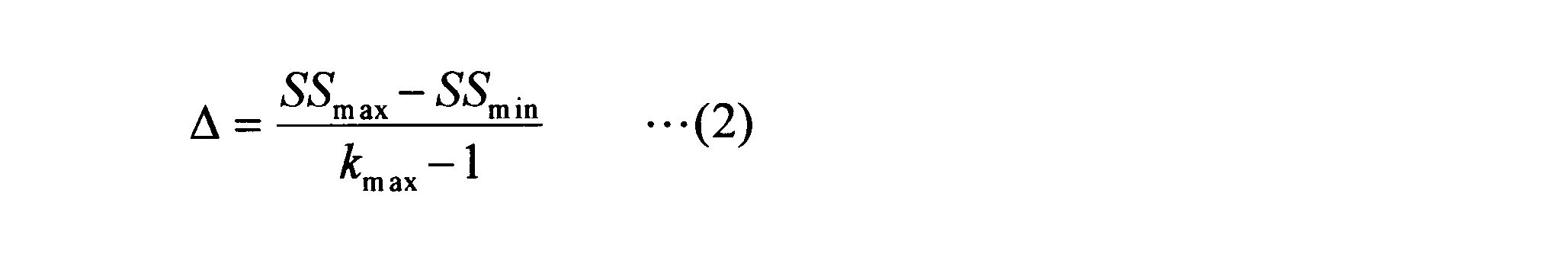
- the k-th shutter speed SS (k) may be set as shown in Expression (3).
- SS max 100 ms
- SS min 1 ms
- ⁇ 19.8 ms
- SS (1) 100 ms
- SS (2) 80.2
- SS (3) 60. 4
- SS (4) 40.6
- SS (5) 20.8 ms
- SS (6) 1 ms.
- the first pixel that becomes the effective pixel (the pixel that has the characteristic curve in the elliptical frame) is a relatively dark pixel.
- gradually bright pixels begin to become effective pixels, and finally only extremely bright pixels become effective pixels.
- the shutter speed change pitch ⁇ it is desirable to set the shutter speed change pitch ⁇ more finely as the shutter speed is lower, instead of making the shutter speed change pitch ⁇ constant.
- the change pitch ⁇ ′ on the logarithmic scale of the shutter speed may be made constant instead of making the change pitch ⁇ of the shutter speed constant.
- FIG. 12 represents the horizontal axis (shutter speed) of FIG. 11 on a logarithmic scale.
- the shutter speeds SS (0) to SS (6) are set evenly on the logarithmic scale.
- the change pitch ⁇ ′ on the logarithmic scale of the shutter speed may be set as shown in Expression (4).
- the k-th shutter speed SS (k) may be set as shown in Expression (5).
- the shutter speed change pitch ⁇ is set more finely as the shutter speed is lower.
- the number of pixels that cannot be effective pixels (marked with * in FIG. 11) can be reduced.
- the number of pixels that cannot be effective pixels is zero.
- the shutter speed of the image sensor 26 is changed in order to provide a difference in the exposure amount between the measurement conditions of k max .
- the shutter speed of the image sensor 26 is changed to any one of the optical paths from the light source to the image sensor.
- the aperture value of the aperture may be changed.
- the light source power of the projection unit 13 may be changed.
- the transmittance of any optical path from the light source to the image sensor may be changed (in this case, a plurality of filters having different transmittances are attached, and one of these filters is selectively transferred to the optical path. Use an insertable mechanism.)
- the 4-bucket method in which the number of fringe images necessary for calculating the initial phase is 4 is applied to the phase shift method of the above embodiment
- Other phase shift methods such as the 7-bucket method may be applied.
- a plurality of sets of fringe image sets are acquired with a plurality of exposure amounts, and processing for selecting an appropriate luminance value set from the plurality of sets of stripe image sets is performed for each region on the measurement target.
- the initial phase data (and height data) for each region was calculated based on the appropriate luminance value set for each region, but the following modifications may be made.
- a set of fringe image sets is acquired with one exposure amount, and the luminance value of an area where the exposure amount is appropriate on the measurement object from the stripe image set.
- a set that is, a luminance value set in which all luminance values in the set are within the effective luminance range
- initial phase data (and height in the region on the measurement object) Data is selected, and based on the selected luminance value set, initial phase data (and height in the region on the measurement object) Data).
- the sine lattice pattern is used as the pattern projected onto the measurement object.
- a pattern other than the sine lattice pattern may be used as long as it has a repetitive structure.
- the program stored in the storage unit 16 of the above embodiment may be a firmware program updated by version upgrade or the like. That is, the analysis process (FIGS. 4 and 9) of the above-described embodiment may be provided by updating an existing analysis process firmware program.
Landscapes
- Engineering & Computer Science (AREA)
- Physics & Mathematics (AREA)
- General Physics & Mathematics (AREA)
- Computer Vision & Pattern Recognition (AREA)
- Multimedia (AREA)
- Signal Processing (AREA)
- Length Measuring Devices By Optical Means (AREA)
- Image Processing (AREA)
Abstract
Description
以下、本発明の第1実施形態として三次元形状測定装置を説明する。
以下、本発明の第2実施形態を説明する。ここでは、第1実施形態との相違点のみを説明する。第1実施形態との相違点は、解析に関するCPU15の動作にある。
以下、上述したkmax通りの測定条件(ここではkmax通りのシャッター速度)の決定方法を説明する。


なお、上記実施形態では、kmax通りの測定条件の間の露光量に差異を設けるために、撮像素子26のシャッター速度を変更したが、光源から撮像素子までの何れかの光路に配置された絞り(開口絞り)の絞り値を変更してもよい。或いは、投影部13の光源パワーを変更してもよい。或いは、光源から撮像素子までの何れかの光路の透過率を変更してもよい(その場合は、透過率の異なる複数のフィルタを装着し、それらのフィルタのうち1つを選択的に光路へ挿入可能な機構を使用するとよい。)。
Claims (16)
- 共通の繰り返し構造を有し、かつ位相の異なる複数種類のパターンを測定対象物上へ順次に投影する投影部と、
前記複数種類のパターンの各々が前記測定対象物へ投影される毎に前記測定対象物を撮像して画像データセットを取得する撮像部と、
取得された前記画像データセットの中から、前記測定対象物上の同一領域に関するデータセットであって、セット内の全データが有効輝度範囲内に収まっているものを、適正データセットとして選出する選出部と、
選出された前記適正データセットに基づき、前記測定対象物において前記適正データの取得元となった領域の形状を求める形状算出部と、
を備えたことを特徴とする形状測定装置。 - 請求項1に記載の形状測定装置において、
複数通りの露光量の各々で前記撮像部に前記画像データセットを取得させることにより複数組みの前記画像データセットを取得する制御部を更に備え、
前記選出部は、
前記複数組みの前記画像データセットの中から前記適正データセットを選出する処理を前記測定対象物上の領域毎に行う
ことを特徴とする形状測定装置。 - 請求項2に記載の形状測定装置において、
前記選出部は、
前記複数組みの前記画像データセットのうち、前記撮像部の入出力特性が線形となる前記有効輝度範囲内に輝度値が収まっているデータセットを、前記適正データセットとして選出する
ことを特徴とする請求項2に記載の形状測定装置。 - 請求項3に記載の形状測定装置において、
前記選出部は、
前記複数組みの前記画像データセットのうち、前記有効輝度範囲内に輝度値が収まっており、かつ、なるべく露光量の高いデータセットを、前記適正データセットとして選出する
ことを特徴とする形状測定装置。 - 請求項2~請求項4の何れか一項に記載の形状測定装置において、
前記制御部は、
前記複数通りの露光量の間のピッチを、前記露光量が低いときほど細かく設定する
ことを特徴とする形状測定装置。 - 請求項5に記載の形状測定装置において、
前記制御部は、
前記複数通りの露光量の間のピッチを、前記露光量の対数目盛上で均等になるように設定する
ことを特徴とする形状測定装置。 - 請求項2~請求項6の何れか一項に記載の形状測定装置において、
前記制御部は、
前記複数組みの画像データセットの取得に先立ち前記複数通りの露光量の値範囲を設定する設定部を更に備え、
前記設定部は、
前記露光量の値範囲の上限値を、前記測定対象物上で最も暗い部分のデータが前記有効輝度範囲内に収まるような値に設定し、かつ、前記露光量の値範囲の下限値を、前記測定対象物上で最も明るい部分のデータが前記有効輝度範囲内に収まるような値に設定する
ことを特徴とする形状測定装置。 - 請求項2~請求項7の何れか一項に記載の形状測定装置において、
前記制御部は、
前記撮像部の電荷蓄積時間を変化させることにより前記複数通りの露光量を設定する
ことを特徴とする形状測定装置。 - 共通の繰り返し構造を有し、かつ位相の異なる複数種類のパターンを測定対象物上へ順次に投影する投影手順と、
前記複数種類のパターンの各々が前記測定対象物へ投影される毎に前記測定対象物を撮像して画像データセットを取得する撮像手順と、
前記測定対象物上の同一領域に関するデータセットであって、セット内の全データが有効輝度範囲内に収まっているものを、適正データセットとして選出する選出手順と、
選出された前記適正データセットに基づき、前記測定対象物において前記適正データの取得元となった領域の形状を求める形状算出手順と、
を含むことを特徴とする形状測定方法。 - 請求項9に記載の形状測定方法において、
複数通りの露光量の各々で前記撮像手順に前記画像データセットを取得させることにより複数組みの前記画像データセットを取得する制御手順を更に含み、
前記選出手順では、
前記複数組みの前記画像データセットの中から前記適正データセットを選出する処理を前記測定対象物上の領域毎に行う
ことを特徴とする形状測定方法。 - 請求項10に記載の形状測定方法において、
前記選出手順では、
前記複数組みの前記画像データセットのうち、前記撮像部の入出力特性が線形となる前記有効輝度範囲内に輝度値が収まっているデータセットを、前記適正データセットとして選出する
ことを特徴とする請求項2に記載の形状測定方法。 - 請求項10又は請求項11に記載の形状測定方法において、
前記選出手順では、
前記複数組みの前記画像データセットのうち、前記有効輝度範囲内に輝度値が収まっており、かつ、なるべく露光量の高いデータセットを、前記適正データセットとして選出する
ことを特徴とする形状測定方法。 - 請求項10~請求項12の何れか一項に記載の形状測定方法において、
前記制御手順では、
前記複数通りの露光量の間のピッチを、前記露光量が低いときほど細かく設定する
ことを特徴とする形状測定方法。 - 請求項13に記載の状測定方法において、
前記制御手順では、
前記複数通りの露光量の間のピッチを、前記露光量の対数目盛上で均等になるように設定する
ことを特徴とする形状測定方法。 - 請求項10~請求項14の何れか一項に記載の形状測定方法において、
前記制御手順は、
前記複数組みの画像データセットの取得に先立ち前記複数通りの露光量の値範囲を設定する設定手順を更に含み、
前記設定手順では、
前記露光量の値範囲の上限値を、前記測定対象物上で最も暗い部分のデータが前記有効輝度範囲内に収まるような値に設定し、かつ、前記露光量の値範囲の下限値を、前記測定対象物上で最も明るい部分のデータが前記有効輝度範囲内に収まるような値に設定する
ことを特徴とする形状測定方法。 - 請求項10~請求項15の何れか一項に記載の形状測定方法において、
前記制御手順では、
前記撮像手順の電荷蓄積時間を変化させることにより前記複数通りの露光量を設定する
ことを特徴とする形状測定方法。
Priority Applications (5)
| Application Number | Priority Date | Filing Date | Title |
|---|---|---|---|
| JP2012515746A JP5825254B2 (ja) | 2010-05-19 | 2011-05-16 | 形状測定装置及び形状測定方法 |
| CN2011800247329A CN102906536A (zh) | 2010-05-19 | 2011-05-16 | 形状测定装置及形状测定方法 |
| KR1020127030144A KR20130072213A (ko) | 2010-05-19 | 2011-05-16 | 형상 측정 장치 및 형상 측정 방법 |
| EP11783256.8A EP2573510B1 (en) | 2010-05-19 | 2011-05-16 | Shape measuring device and shape measuring method |
| US13/680,861 US9194697B2 (en) | 2010-05-19 | 2012-11-19 | Apparatus and method for measuring three-dimensional objects |
Applications Claiming Priority (2)
| Application Number | Priority Date | Filing Date | Title |
|---|---|---|---|
| JP2010-115325 | 2010-05-19 | ||
| JP2010115325 | 2010-05-19 |
Related Child Applications (1)
| Application Number | Title | Priority Date | Filing Date |
|---|---|---|---|
| US13/680,861 Continuation US9194697B2 (en) | 2010-05-19 | 2012-11-19 | Apparatus and method for measuring three-dimensional objects |
Publications (1)
| Publication Number | Publication Date |
|---|---|
| WO2011145319A1 true WO2011145319A1 (ja) | 2011-11-24 |
Family
ID=44991437
Family Applications (1)
| Application Number | Title | Priority Date | Filing Date |
|---|---|---|---|
| PCT/JP2011/002703 Ceased WO2011145319A1 (ja) | 2010-05-19 | 2011-05-16 | 形状測定装置及び形状測定方法 |
Country Status (6)
| Country | Link |
|---|---|
| US (1) | US9194697B2 (ja) |
| EP (1) | EP2573510B1 (ja) |
| JP (1) | JP5825254B2 (ja) |
| KR (1) | KR20130072213A (ja) |
| CN (1) | CN102906536A (ja) |
| WO (1) | WO2011145319A1 (ja) |
Cited By (9)
| Publication number | Priority date | Publication date | Assignee | Title |
|---|---|---|---|---|
| WO2013021568A1 (ja) * | 2011-08-05 | 2013-02-14 | ソニー株式会社 | 3次元測定装置、3次元測定方法及びプログラム |
| JP2014025782A (ja) * | 2012-07-26 | 2014-02-06 | Toyota Central R&D Labs Inc | 形状測定装置 |
| JP2015222220A (ja) * | 2014-05-23 | 2015-12-10 | セイコーエプソン株式会社 | 制御装置、ロボット、及び制御方法 |
| WO2018047252A1 (ja) * | 2016-09-07 | 2018-03-15 | 富士機械製造株式会社 | 認識装置 |
| JP2018044960A (ja) * | 2017-12-25 | 2018-03-22 | 株式会社キーエンス | 三次元画像処理装置、三次元画像処理装置用ヘッド部、三次元画像処理方法、三次元画像処理プログラム及びコンピュータで読み取り可能な記録媒体並びに記録した機器 |
| JP2019027947A (ja) * | 2017-07-31 | 2019-02-21 | 株式会社キーエンス | 形状測定装置及び形状測定方法 |
| CN109612404A (zh) * | 2012-11-14 | 2019-04-12 | 高通股份有限公司 | 结构光主动深度感测系统中对光源功率的动态调整 |
| JP2021050974A (ja) * | 2019-09-24 | 2021-04-01 | 株式会社デンソーウェーブ | 縞パターン画像決定方法および三次元計測装置 |
| JP2021185510A (ja) * | 2016-03-07 | 2021-12-09 | ハイラ・インコーポレイテッドHyla, Inc. | デバイスの画面損傷検出 |
Families Citing this family (8)
| Publication number | Priority date | Publication date | Assignee | Title |
|---|---|---|---|---|
| CN103575235A (zh) * | 2013-11-08 | 2014-02-12 | 湖北汽车工业学院 | 一种基于数字条纹投影的微型三维测量系统 |
| USD724452S1 (en) * | 2014-04-28 | 2015-03-17 | Stephen Mate | Laser thickness gauge |
| CN104111038B (zh) * | 2014-07-07 | 2016-08-17 | 四川大学 | 利用相位融合算法修复饱和产生的相位误差的方法 |
| US9762793B2 (en) * | 2014-10-21 | 2017-09-12 | Hand Held Products, Inc. | System and method for dimensioning |
| JP2017110991A (ja) * | 2015-12-16 | 2017-06-22 | セイコーエプソン株式会社 | 計測システム、計測方法、ロボット制御方法、ロボット、ロボットシステムおよびピッキング装置 |
| CN106959551B (zh) * | 2016-01-08 | 2023-12-19 | 京东方科技集团股份有限公司 | 一种显示装置及其驱动方法 |
| KR101842141B1 (ko) * | 2016-05-13 | 2018-03-26 | (주)칼리온 | 3차원 스캐닝 장치 및 방법 |
| US20240377538A1 (en) * | 2023-05-08 | 2024-11-14 | Microsoft Technology Licensing, Llc | Hybrid depth imaging with sparse subject irradiation |
Citations (8)
| Publication number | Priority date | Publication date | Assignee | Title |
|---|---|---|---|---|
| JPS6221011A (ja) * | 1985-07-19 | 1987-01-29 | Nissan Motor Co Ltd | 光切断法による計測装置 |
| JPH05340727A (ja) * | 1992-06-05 | 1993-12-21 | Yunisun:Kk | 三次元形状計測装置 |
| JPH0658726A (ja) * | 1992-08-04 | 1994-03-04 | Mitsubishi Heavy Ind Ltd | 光切断方法における異常光除去方法 |
| JP2002357408A (ja) * | 2001-03-25 | 2002-12-13 | Omron Corp | 光学式計測装置 |
| JP2005214653A (ja) | 2004-01-27 | 2005-08-11 | Olympus Corp | 3次元形状測定方法及びその装置 |
| JP2006300539A (ja) * | 2005-04-15 | 2006-11-02 | Ckd Corp | 三次元計測装置及び基板検査装置 |
| JP2006527372A (ja) * | 2003-06-11 | 2006-11-30 | ソルヴィジョン | 感度及びダイナミックレンジを増大させた3d及び2d測定システム及びその方法 |
| JP2008096117A (ja) * | 2006-10-05 | 2008-04-24 | Keyence Corp | 光学式変位計、光学式変位測定方法、光学式変位測定プログラム及びコンピュータで読み取り可能な記録媒体並びに記録した機器 |
Family Cites Families (21)
| Publication number | Priority date | Publication date | Assignee | Title |
|---|---|---|---|---|
| US4666303A (en) * | 1983-07-11 | 1987-05-19 | Diffracto Ltd. | Electro-optical gap and flushness sensors |
| US4736214A (en) * | 1984-01-09 | 1988-04-05 | Rogers Robert E | Apparatus and method for producing three-dimensional images from two-dimensional sources |
| JPH11125508A (ja) * | 1997-10-21 | 1999-05-11 | Toyota Central Res & Dev Lab Inc | 断面形状測定方法 |
| US6191809B1 (en) * | 1998-01-15 | 2001-02-20 | Vista Medical Technologies, Inc. | Method and apparatus for aligning stereo images |
| US6606413B1 (en) * | 1998-06-01 | 2003-08-12 | Trestle Acquisition Corp. | Compression packaged image transmission for telemicroscopy |
| US6711283B1 (en) * | 2000-05-03 | 2004-03-23 | Aperio Technologies, Inc. | Fully automatic rapid microscope slide scanner |
| JP4256059B2 (ja) * | 2000-10-04 | 2009-04-22 | シーケーディ株式会社 | 三次元計測装置 |
| DE10212916B4 (de) * | 2001-03-25 | 2016-12-22 | Omron Corp. | Optischer Versetzungssensor und Verfahren zum Verarbeiten von Bildern unter Verwendung eines optischen Versetzungssensors |
| JP3878023B2 (ja) * | 2002-02-01 | 2007-02-07 | シーケーディ株式会社 | 三次元計測装置 |
| AU2003287803A1 (en) * | 2002-11-21 | 2004-06-15 | Solvision | Fast 3d height measurement method and system |
| US7224437B2 (en) * | 2005-05-31 | 2007-05-29 | Invarium, Inc | Method for measuring and verifying stepper illumination |
| US20070177820A1 (en) * | 2006-01-27 | 2007-08-02 | O Ruanaidh Joseph J | System and method for providing an optical section image by direct phase angle determination and use of more than three images |
| US7729559B2 (en) * | 2006-05-22 | 2010-06-01 | Ge Healthcare Bio-Sciences Corp. | System and method for optical section image line removal |
| WO2008049916A1 (en) * | 2006-10-26 | 2008-05-02 | Seereal Technologies S.A. | Mobile tlephony system comprising holographic display |
| CN101652626B (zh) * | 2007-04-05 | 2011-07-13 | 株式会社尼康 | 形状测定装置及形状测定方法 |
| JP4998077B2 (ja) * | 2007-05-09 | 2012-08-15 | パルステック工業株式会社 | 3次元形状測定装置および3次元形状測定方法 |
| JP2009031150A (ja) * | 2007-07-27 | 2009-02-12 | Omron Corp | 三次元形状計測装置、三次元形状計測方法、三次元形状計測プログラム、および記録媒体 |
| US8107083B2 (en) * | 2008-03-05 | 2012-01-31 | General Electric Company | System aspects for a probe system that utilizes structured-light |
| JP5432625B2 (ja) * | 2009-07-29 | 2014-03-05 | 株式会社トプコン | 眼科観察装置 |
| CN101694375B (zh) * | 2009-10-23 | 2011-06-22 | 北京航空航天大学 | 一种用于强反射表面三维形貌测量的立体视觉检测方法 |
| US8111905B2 (en) * | 2009-10-29 | 2012-02-07 | Mitutoyo Corporation | Autofocus video tool and method for precise dimensional inspection |
-
2011
- 2011-05-16 WO PCT/JP2011/002703 patent/WO2011145319A1/ja not_active Ceased
- 2011-05-16 CN CN2011800247329A patent/CN102906536A/zh active Pending
- 2011-05-16 JP JP2012515746A patent/JP5825254B2/ja active Active
- 2011-05-16 KR KR1020127030144A patent/KR20130072213A/ko not_active Withdrawn
- 2011-05-16 EP EP11783256.8A patent/EP2573510B1/en active Active
-
2012
- 2012-11-19 US US13/680,861 patent/US9194697B2/en active Active
Patent Citations (8)
| Publication number | Priority date | Publication date | Assignee | Title |
|---|---|---|---|---|
| JPS6221011A (ja) * | 1985-07-19 | 1987-01-29 | Nissan Motor Co Ltd | 光切断法による計測装置 |
| JPH05340727A (ja) * | 1992-06-05 | 1993-12-21 | Yunisun:Kk | 三次元形状計測装置 |
| JPH0658726A (ja) * | 1992-08-04 | 1994-03-04 | Mitsubishi Heavy Ind Ltd | 光切断方法における異常光除去方法 |
| JP2002357408A (ja) * | 2001-03-25 | 2002-12-13 | Omron Corp | 光学式計測装置 |
| JP2006527372A (ja) * | 2003-06-11 | 2006-11-30 | ソルヴィジョン | 感度及びダイナミックレンジを増大させた3d及び2d測定システム及びその方法 |
| JP2005214653A (ja) | 2004-01-27 | 2005-08-11 | Olympus Corp | 3次元形状測定方法及びその装置 |
| JP2006300539A (ja) * | 2005-04-15 | 2006-11-02 | Ckd Corp | 三次元計測装置及び基板検査装置 |
| JP2008096117A (ja) * | 2006-10-05 | 2008-04-24 | Keyence Corp | 光学式変位計、光学式変位測定方法、光学式変位測定プログラム及びコンピュータで読み取り可能な記録媒体並びに記録した機器 |
Cited By (15)
| Publication number | Priority date | Publication date | Assignee | Title |
|---|---|---|---|---|
| JP2013036791A (ja) * | 2011-08-05 | 2013-02-21 | Sony Corp | 3次元測定装置、3次元測定方法及びプログラム |
| WO2013021568A1 (ja) * | 2011-08-05 | 2013-02-14 | ソニー株式会社 | 3次元測定装置、3次元測定方法及びプログラム |
| JP2014025782A (ja) * | 2012-07-26 | 2014-02-06 | Toyota Central R&D Labs Inc | 形状測定装置 |
| CN109612404A (zh) * | 2012-11-14 | 2019-04-12 | 高通股份有限公司 | 结构光主动深度感测系统中对光源功率的动态调整 |
| US11509880B2 (en) | 2012-11-14 | 2022-11-22 | Qualcomm Incorporated | Dynamic adjustment of light source power in structured light active depth sensing systems |
| CN109612404B (zh) * | 2012-11-14 | 2021-02-26 | 高通股份有限公司 | 结构光主动深度感测系统中对光源功率的动态调整 |
| JP2015222220A (ja) * | 2014-05-23 | 2015-12-10 | セイコーエプソン株式会社 | 制御装置、ロボット、及び制御方法 |
| JP2021185510A (ja) * | 2016-03-07 | 2021-12-09 | ハイラ・インコーポレイテッドHyla, Inc. | デバイスの画面損傷検出 |
| JP7417793B2 (ja) | 2016-03-07 | 2024-01-19 | アシュラント インコーポレイテッド | デバイスの画面損傷検出 |
| JPWO2018047252A1 (ja) * | 2016-09-07 | 2019-06-24 | 株式会社Fuji | 認識装置 |
| WO2018047252A1 (ja) * | 2016-09-07 | 2018-03-15 | 富士機械製造株式会社 | 認識装置 |
| JP2019027947A (ja) * | 2017-07-31 | 2019-02-21 | 株式会社キーエンス | 形状測定装置及び形状測定方法 |
| JP2018044960A (ja) * | 2017-12-25 | 2018-03-22 | 株式会社キーエンス | 三次元画像処理装置、三次元画像処理装置用ヘッド部、三次元画像処理方法、三次元画像処理プログラム及びコンピュータで読み取り可能な記録媒体並びに記録した機器 |
| JP2021050974A (ja) * | 2019-09-24 | 2021-04-01 | 株式会社デンソーウェーブ | 縞パターン画像決定方法および三次元計測装置 |
| JP7294026B2 (ja) | 2019-09-24 | 2023-06-20 | 株式会社デンソーウェーブ | 縞パターン画像決定方法 |
Also Published As
| Publication number | Publication date |
|---|---|
| EP2573510A4 (en) | 2016-11-16 |
| JP5825254B2 (ja) | 2015-12-02 |
| JPWO2011145319A1 (ja) | 2013-07-22 |
| KR20130072213A (ko) | 2013-07-01 |
| EP2573510A1 (en) | 2013-03-27 |
| US20130076895A1 (en) | 2013-03-28 |
| US9194697B2 (en) | 2015-11-24 |
| EP2573510B1 (en) | 2018-02-14 |
| CN102906536A (zh) | 2013-01-30 |
Similar Documents
| Publication | Publication Date | Title |
|---|---|---|
| JP5825254B2 (ja) | 形状測定装置及び形状測定方法 | |
| US8514389B2 (en) | Inspecting apparatus, three-dimensional profile measuring apparatus, and manufacturing method of structure | |
| JP5443303B2 (ja) | 外観検査装置及び外観検査方法 | |
| JP5016520B2 (ja) | 3次元形状計測方法および装置 | |
| JP5576726B2 (ja) | 三次元計測装置、三次元計測方法、及びプログラム | |
| JP4077754B2 (ja) | 3次元形状測定装置 | |
| JP2010243438A (ja) | 三次元形状測定装置及び三次元形状測定方法 | |
| JPH0921620A (ja) | 物体の三次元形状計測方法 | |
| WO2012057284A1 (ja) | 三次元形状測定装置、三次元形状測定方法、構造物の製造方法および構造物製造システム | |
| JP5682419B2 (ja) | 検査方法及び検査装置 | |
| JP2012093235A (ja) | 三次元形状測定装置、三次元形状測定方法、構造物の製造方法および構造物製造システム | |
| JP2009180689A (ja) | 三次元形状測定装置 | |
| TWI460419B (zh) | 檢查偵測裝置之方法以及建立偵測裝置的測量變數之方法 | |
| JP2010169572A (ja) | 演算装置、演算プログラム、面形状測定装置、及び面形状測定方法 | |
| JP2011021970A (ja) | 三次元形状測定装置および三次元形状測定方法 | |
| JP5986357B2 (ja) | 三次元計測装置、三次元計測装置の制御方法、およびプログラム | |
| JP5895733B2 (ja) | 表面欠陥検査装置および表面欠陥検査方法 | |
| JP7624314B2 (ja) | 画像処理装置 | |
| JP2008170282A (ja) | 形状測定装置 | |
| JP2009204373A (ja) | 光投影装置および三次元形状測定装置 | |
| JP7688978B2 (ja) | 画像処理装置 | |
| JP7667412B2 (ja) | 表面形状測定方法及び表面形状測定装置 | |
| JP2010210507A (ja) | 測定装置及び測定方法 | |
| CN110163919B (zh) | 三维建模方法及装置 | |
| JP2019086483A (ja) | 検査装置の高さ情報の取得方法及び検査装置 |
Legal Events
| Date | Code | Title | Description |
|---|---|---|---|
| WWE | Wipo information: entry into national phase |
Ref document number: 201180024732.9 Country of ref document: CN |
|
| 121 | Ep: the epo has been informed by wipo that ep was designated in this application |
Ref document number: 11783256 Country of ref document: EP Kind code of ref document: A1 |
|
| WWE | Wipo information: entry into national phase |
Ref document number: 2012515746 Country of ref document: JP |
|
| ENP | Entry into the national phase |
Ref document number: 20127030144 Country of ref document: KR Kind code of ref document: A |
|
| NENP | Non-entry into the national phase |
Ref country code: DE |
|
| WWE | Wipo information: entry into national phase |
Ref document number: 2011783256 Country of ref document: EP |