WO2011145434A1 - アンモニア燃焼内燃機関 - Google Patents
アンモニア燃焼内燃機関 Download PDFInfo
- Publication number
- WO2011145434A1 WO2011145434A1 PCT/JP2011/059991 JP2011059991W WO2011145434A1 WO 2011145434 A1 WO2011145434 A1 WO 2011145434A1 JP 2011059991 W JP2011059991 W JP 2011059991W WO 2011145434 A1 WO2011145434 A1 WO 2011145434A1
- Authority
- WO
- WIPO (PCT)
- Prior art keywords
- ammonia
- engine
- supplied
- reformer
- ratio
- Prior art date
- Legal status (The legal status is an assumption and is not a legal conclusion. Google has not performed a legal analysis and makes no representation as to the accuracy of the status listed.)
- Ceased
Links
Images




Classifications
-
- F—MECHANICAL ENGINEERING; LIGHTING; HEATING; WEAPONS; BLASTING
- F02—COMBUSTION ENGINES; HOT-GAS OR COMBUSTION-PRODUCT ENGINE PLANTS
- F02M—SUPPLYING COMBUSTION ENGINES IN GENERAL WITH COMBUSTIBLE MIXTURES OR CONSTITUENTS THEREOF
- F02M31/00—Apparatus for thermally treating combustion-air, fuel, or fuel-air mixture
- F02M31/02—Apparatus for thermally treating combustion-air, fuel, or fuel-air mixture for heating
- F02M31/14—Apparatus for thermally treating combustion-air, fuel, or fuel-air mixture for heating by using heat from working cylinders or cylinder heads
-
- F—MECHANICAL ENGINEERING; LIGHTING; HEATING; WEAPONS; BLASTING
- F01—MACHINES OR ENGINES IN GENERAL; ENGINE PLANTS IN GENERAL; STEAM ENGINES
- F01N—GAS-FLOW SILENCERS OR EXHAUST APPARATUS FOR MACHINES OR ENGINES IN GENERAL; GAS-FLOW SILENCERS OR EXHAUST APPARATUS FOR INTERNAL-COMBUSTION ENGINES
- F01N3/00—Exhaust or silencing apparatus having means for purifying, rendering innocuous, or otherwise treating exhaust
- F01N3/08—Exhaust or silencing apparatus having means for purifying, rendering innocuous, or otherwise treating exhaust for rendering innocuous
- F01N3/10—Exhaust or silencing apparatus having means for purifying, rendering innocuous, or otherwise treating exhaust for rendering innocuous by thermal or catalytic conversion of noxious components of exhaust
- F01N3/24—Exhaust or silencing apparatus having means for purifying, rendering innocuous, or otherwise treating exhaust for rendering innocuous by thermal or catalytic conversion of noxious components of exhaust characterised by constructional aspects of converting apparatus
- F01N3/30—Arrangements for supply of additional air
-
- F—MECHANICAL ENGINEERING; LIGHTING; HEATING; WEAPONS; BLASTING
- F01—MACHINES OR ENGINES IN GENERAL; ENGINE PLANTS IN GENERAL; STEAM ENGINES
- F01N—GAS-FLOW SILENCERS OR EXHAUST APPARATUS FOR MACHINES OR ENGINES IN GENERAL; GAS-FLOW SILENCERS OR EXHAUST APPARATUS FOR INTERNAL-COMBUSTION ENGINES
- F01N9/00—Electrical control of exhaust gas treating apparatus
-
- F—MECHANICAL ENGINEERING; LIGHTING; HEATING; WEAPONS; BLASTING
- F02—COMBUSTION ENGINES; HOT-GAS OR COMBUSTION-PRODUCT ENGINE PLANTS
- F02D—CONTROLLING COMBUSTION ENGINES
- F02D19/00—Controlling engines characterised by their use of non-liquid fuels, pluralities of fuels, or non-fuel substances added to the combustible mixtures
- F02D19/06—Controlling engines characterised by their use of non-liquid fuels, pluralities of fuels, or non-fuel substances added to the combustible mixtures peculiar to engines working with pluralities of fuels, e.g. alternatively with light and heavy fuel oil, other than engines indifferent to the fuel consumed
- F02D19/0639—Controlling engines characterised by their use of non-liquid fuels, pluralities of fuels, or non-fuel substances added to the combustible mixtures peculiar to engines working with pluralities of fuels, e.g. alternatively with light and heavy fuel oil, other than engines indifferent to the fuel consumed characterised by the type of fuels
- F02D19/0642—Controlling engines characterised by their use of non-liquid fuels, pluralities of fuels, or non-fuel substances added to the combustible mixtures peculiar to engines working with pluralities of fuels, e.g. alternatively with light and heavy fuel oil, other than engines indifferent to the fuel consumed characterised by the type of fuels at least one fuel being gaseous, the other fuels being gaseous or liquid at standard conditions
- F02D19/0644—Controlling engines characterised by their use of non-liquid fuels, pluralities of fuels, or non-fuel substances added to the combustible mixtures peculiar to engines working with pluralities of fuels, e.g. alternatively with light and heavy fuel oil, other than engines indifferent to the fuel consumed characterised by the type of fuels at least one fuel being gaseous, the other fuels being gaseous or liquid at standard conditions the gaseous fuel being hydrogen, ammonia or carbon monoxide
-
- F—MECHANICAL ENGINEERING; LIGHTING; HEATING; WEAPONS; BLASTING
- F02—COMBUSTION ENGINES; HOT-GAS OR COMBUSTION-PRODUCT ENGINE PLANTS
- F02D—CONTROLLING COMBUSTION ENGINES
- F02D19/00—Controlling engines characterised by their use of non-liquid fuels, pluralities of fuels, or non-fuel substances added to the combustible mixtures
- F02D19/06—Controlling engines characterised by their use of non-liquid fuels, pluralities of fuels, or non-fuel substances added to the combustible mixtures peculiar to engines working with pluralities of fuels, e.g. alternatively with light and heavy fuel oil, other than engines indifferent to the fuel consumed
- F02D19/0663—Details on the fuel supply system, e.g. tanks, valves, pipes, pumps, rails, injectors or mixers
- F02D19/0668—Treating or cleaning means; Fuel filters
- F02D19/0671—Means to generate or modify a fuel, e.g. reformers, electrolytic cells or membranes
-
- F—MECHANICAL ENGINEERING; LIGHTING; HEATING; WEAPONS; BLASTING
- F02—COMBUSTION ENGINES; HOT-GAS OR COMBUSTION-PRODUCT ENGINE PLANTS
- F02D—CONTROLLING COMBUSTION ENGINES
- F02D19/00—Controlling engines characterised by their use of non-liquid fuels, pluralities of fuels, or non-fuel substances added to the combustible mixtures
- F02D19/06—Controlling engines characterised by their use of non-liquid fuels, pluralities of fuels, or non-fuel substances added to the combustible mixtures peculiar to engines working with pluralities of fuels, e.g. alternatively with light and heavy fuel oil, other than engines indifferent to the fuel consumed
- F02D19/08—Controlling engines characterised by their use of non-liquid fuels, pluralities of fuels, or non-fuel substances added to the combustible mixtures peculiar to engines working with pluralities of fuels, e.g. alternatively with light and heavy fuel oil, other than engines indifferent to the fuel consumed simultaneously using pluralities of fuels
- F02D19/081—Adjusting the fuel composition or mixing ratio; Transitioning from one fuel to the other
-
- F—MECHANICAL ENGINEERING; LIGHTING; HEATING; WEAPONS; BLASTING
- F02—COMBUSTION ENGINES; HOT-GAS OR COMBUSTION-PRODUCT ENGINE PLANTS
- F02D—CONTROLLING COMBUSTION ENGINES
- F02D41/00—Electrical control of supply of combustible mixture or its constituents
- F02D41/0025—Controlling engines characterised by use of non-liquid fuels, pluralities of fuels, or non-fuel substances added to the combustible mixtures
-
- F—MECHANICAL ENGINEERING; LIGHTING; HEATING; WEAPONS; BLASTING
- F02—COMBUSTION ENGINES; HOT-GAS OR COMBUSTION-PRODUCT ENGINE PLANTS
- F02D—CONTROLLING COMBUSTION ENGINES
- F02D41/00—Electrical control of supply of combustible mixture or its constituents
- F02D41/02—Circuit arrangements for generating control signals
- F02D41/021—Introducing corrections for particular conditions exterior to the engine
- F02D41/0235—Introducing corrections for particular conditions exterior to the engine in relation with the state of the exhaust gas treating apparatus
-
- F—MECHANICAL ENGINEERING; LIGHTING; HEATING; WEAPONS; BLASTING
- F02—COMBUSTION ENGINES; HOT-GAS OR COMBUSTION-PRODUCT ENGINE PLANTS
- F02M—SUPPLYING COMBUSTION ENGINES IN GENERAL WITH COMBUSTIBLE MIXTURES OR CONSTITUENTS THEREOF
- F02M23/00—Apparatus for adding secondary air to fuel-air mixture
- F02M23/04—Apparatus for adding secondary air to fuel-air mixture with automatic control
- F02M23/10—Apparatus for adding secondary air to fuel-air mixture with automatic control dependent on temperature, e.g. engine temperature
-
- F—MECHANICAL ENGINEERING; LIGHTING; HEATING; WEAPONS; BLASTING
- F02—COMBUSTION ENGINES; HOT-GAS OR COMBUSTION-PRODUCT ENGINE PLANTS
- F02M—SUPPLYING COMBUSTION ENGINES IN GENERAL WITH COMBUSTIBLE MIXTURES OR CONSTITUENTS THEREOF
- F02M31/00—Apparatus for thermally treating combustion-air, fuel, or fuel-air mixture
- F02M31/02—Apparatus for thermally treating combustion-air, fuel, or fuel-air mixture for heating
- F02M31/16—Other apparatus for heating fuel
- F02M31/18—Other apparatus for heating fuel to vaporise fuel
-
- F—MECHANICAL ENGINEERING; LIGHTING; HEATING; WEAPONS; BLASTING
- F01—MACHINES OR ENGINES IN GENERAL; ENGINE PLANTS IN GENERAL; STEAM ENGINES
- F01N—GAS-FLOW SILENCERS OR EXHAUST APPARATUS FOR MACHINES OR ENGINES IN GENERAL; GAS-FLOW SILENCERS OR EXHAUST APPARATUS FOR INTERNAL-COMBUSTION ENGINES
- F01N2240/00—Combination or association of two or more different exhaust treating devices, or of at least one such device with an auxiliary device, not covered by indexing codes F01N2230/00 or F01N2250/00, one of the devices being
- F01N2240/30—Combination or association of two or more different exhaust treating devices, or of at least one such device with an auxiliary device, not covered by indexing codes F01N2230/00 or F01N2250/00, one of the devices being a fuel reformer
-
- F—MECHANICAL ENGINEERING; LIGHTING; HEATING; WEAPONS; BLASTING
- F01—MACHINES OR ENGINES IN GENERAL; ENGINE PLANTS IN GENERAL; STEAM ENGINES
- F01N—GAS-FLOW SILENCERS OR EXHAUST APPARATUS FOR MACHINES OR ENGINES IN GENERAL; GAS-FLOW SILENCERS OR EXHAUST APPARATUS FOR INTERNAL-COMBUSTION ENGINES
- F01N2610/00—Adding substances to exhaust gases
- F01N2610/02—Adding substances to exhaust gases the substance being ammonia or urea
-
- F—MECHANICAL ENGINEERING; LIGHTING; HEATING; WEAPONS; BLASTING
- F01—MACHINES OR ENGINES IN GENERAL; ENGINE PLANTS IN GENERAL; STEAM ENGINES
- F01N—GAS-FLOW SILENCERS OR EXHAUST APPARATUS FOR MACHINES OR ENGINES IN GENERAL; GAS-FLOW SILENCERS OR EXHAUST APPARATUS FOR INTERNAL-COMBUSTION ENGINES
- F01N2610/00—Adding substances to exhaust gases
- F01N2610/03—Adding substances to exhaust gases the substance being hydrocarbons, e.g. engine fuel
-
- F—MECHANICAL ENGINEERING; LIGHTING; HEATING; WEAPONS; BLASTING
- F02—COMBUSTION ENGINES; HOT-GAS OR COMBUSTION-PRODUCT ENGINE PLANTS
- F02D—CONTROLLING COMBUSTION ENGINES
- F02D2200/00—Input parameters for engine control
- F02D2200/02—Input parameters for engine control the parameters being related to the engine
- F02D2200/08—Exhaust gas treatment apparatus parameters
- F02D2200/0802—Temperature of the exhaust gas treatment apparatus
-
- Y—GENERAL TAGGING OF NEW TECHNOLOGICAL DEVELOPMENTS; GENERAL TAGGING OF CROSS-SECTIONAL TECHNOLOGIES SPANNING OVER SEVERAL SECTIONS OF THE IPC; TECHNICAL SUBJECTS COVERED BY FORMER USPC CROSS-REFERENCE ART COLLECTIONS [XRACs] AND DIGESTS
- Y02—TECHNOLOGIES OR APPLICATIONS FOR MITIGATION OR ADAPTATION AGAINST CLIMATE CHANGE
- Y02T—CLIMATE CHANGE MITIGATION TECHNOLOGIES RELATED TO TRANSPORTATION
- Y02T10/00—Road transport of goods or passengers
- Y02T10/10—Internal combustion engine [ICE] based vehicles
- Y02T10/12—Improving ICE efficiencies
-
- Y—GENERAL TAGGING OF NEW TECHNOLOGICAL DEVELOPMENTS; GENERAL TAGGING OF CROSS-SECTIONAL TECHNOLOGIES SPANNING OVER SEVERAL SECTIONS OF THE IPC; TECHNICAL SUBJECTS COVERED BY FORMER USPC CROSS-REFERENCE ART COLLECTIONS [XRACs] AND DIGESTS
- Y02—TECHNOLOGIES OR APPLICATIONS FOR MITIGATION OR ADAPTATION AGAINST CLIMATE CHANGE
- Y02T—CLIMATE CHANGE MITIGATION TECHNOLOGIES RELATED TO TRANSPORTATION
- Y02T10/00—Road transport of goods or passengers
- Y02T10/10—Internal combustion engine [ICE] based vehicles
- Y02T10/30—Use of alternative fuels, e.g. biofuels
-
- Y—GENERAL TAGGING OF NEW TECHNOLOGICAL DEVELOPMENTS; GENERAL TAGGING OF CROSS-SECTIONAL TECHNOLOGIES SPANNING OVER SEVERAL SECTIONS OF THE IPC; TECHNICAL SUBJECTS COVERED BY FORMER USPC CROSS-REFERENCE ART COLLECTIONS [XRACs] AND DIGESTS
- Y02—TECHNOLOGIES OR APPLICATIONS FOR MITIGATION OR ADAPTATION AGAINST CLIMATE CHANGE
- Y02T—CLIMATE CHANGE MITIGATION TECHNOLOGIES RELATED TO TRANSPORTATION
- Y02T10/00—Road transport of goods or passengers
- Y02T10/10—Internal combustion engine [ICE] based vehicles
- Y02T10/40—Engine management systems
Definitions
- the present invention relates to an ammonia burning internal combustion engine.
- ammonia is harder to burn than fossil fuels. Therefore, when ammonia is used as a fuel, some device is required to make it easier to burn ammonia. Therefore, in the above-mentioned internal combustion engine, the reformed ammonia is reformed using exhaust heat to generate a reformed gas composed of hydrogen and nitrogen, and the hydrogen in the generated reformed gas is stored in a hydrogen storage alloy and burned. In addition to ammonia, hydrogen stored in the hydrogen storage alloy is supplied into the room so that it can be easily burned even when ammonia is used as the fuel.
- an ammonia burning internal combustion engine using ammonia as a fuel is provided with a reformer that reforms ammonia to generate reformed gas containing hydrogen, and the reformed gas is added to the combustion chamber in addition to ammonia.
- An exhaust purification catalyst is arranged in the engine exhaust passage and a secondary air supply device is arranged in the engine exhaust passage upstream of the exhaust purification catalyst, and the ratio of the supplied ammonia amount to the total supplied fuel amount after the warm-up is completed.
- the ammonia ratio shown is set in advance according to the operating state of the engine, and when the reforming capacity of the reformer is equal to or lower than the predetermined reforming capacity, the ammonia ratio is set in advance according to the operating state of the engine. Increase the ammonia ratio after completion of warm-up and supply secondary air from the secondary air supply device into the engine exhaust passage upstream of the exhaust purification catalyst.
- FIG. 1 is an overall view of an internal combustion engine.
- FIG. 2 is a diagram showing the ammonia ratio RA.
- FIG. 3 is a time chart showing changes in the ammonia ratio RA and the like.
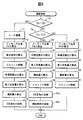
- FIG. 4 is a flowchart for performing operation control.
- FIG. 5 is a time chart showing changes in the ammonia ratio RA and the like.
- FIG. 6 is a flowchart for performing operation control.
- FIG. 7 is a flowchart for performing operation control.
- FIG. 8 is a flowchart for performing operation control.
- 1 is an internal combustion engine body
- 2 is a cylinder block
- 3 is a cylinder head
- 4 is a piston
- 5 is a combustion chamber
- 6 is disposed in the center of the top surface of the combustion chamber 5 and emits a plasma jet.
- a plasma jet spark plug 7 is an intake valve
- 8 is an intake port
- 9 is an exhaust valve
- 10 is an exhaust port.
- the intake port 8 is connected to a surge tank 12 through an intake branch pipe 11, and an ammonia injection valve 13 for injecting gaseous ammonia into the corresponding intake port 8 is arranged in each intake branch pipe 11.
- the surge tank 12 is connected to an air cleaner 15 via an intake duct 14, and a throttle valve 16 driven by an actuator and an intake air amount detector 17 using, for example, heat rays are arranged in the intake duct 14.
- the exhaust port 10 is connected via an exhaust manifold 18 to an exhaust purification catalyst 19 having an oxidation function.
- a reformer 20 and a carburetor 21 are arranged in the exhaust passage downstream of the exhaust purification catalyst 19.
- the carburetor 21 is connected to a fuel tank 23 via an ammonia inflow pipe 22.
- the ammonia inflow pipe 22 is opened during engine operation, and a shutoff valve 24 and a control valve that are closed when the engine is stopped.
- a pressure valve 25 is arranged.
- the fuel tank 23 is filled with high-pressure liquid ammonia of about 0.8 MPa to 1.0 MPa, and the liquid ammonia in the fuel tank 23 is supplied into the vaporizer 21 via the ammonia inflow pipe 22.
- the vaporizer 21 is formed so as to be heated by the exhaust gas. Therefore, the liquid ammonia supplied into the vaporizer 21 is vaporized in the vaporizer 21.
- the gaseous ammonia vaporized in the vaporizer 21 is supplied to the ammonia gas tank 27 via the ammonia outflow pipe 26.
- Gaseous ammonia in the ammonia gas tank 27 is supplied to the ammonia injection valve 13 via the gaseous ammonia supply pipe 28, and gaseous ammonia is injected from the ammonia injection valve 13 into the corresponding intake port 8.
- the vaporizer 21 is connected to the reformer 20 via an ammonia outflow pipe 29, and the reformer that opens when the reformer 20 is performing a reforming action in the ammonia outflow pipe 29.
- a reactor control valve 30 and a check valve 31 that can flow only from the vaporizer 21 toward the reformer 20 are arranged in series.
- the reformer 20 is formed to be heated by exhaust gas, and the reformer 20 further includes an electric heater 32.
- a catalyst for promoting the reforming action of ammonia is disposed in the reformer 20.
- the reformer 20 is provided with a temperature sensor 33 for detecting the temperature in the reformer 20.
- the ammonia supplied from the vaporizer 21 into the reformer 20 is decomposed into hydrogen and nitrogen (2NH 3 ⁇ N 2 + 3H 2 ), ie, reformed.
- a reformed gas containing hydrogen is generated in the reformer 20.
- ammonia is decomposed into hydrogen and nitrogen, the number of moles is doubled, and the thermal expansion of the reformed gas due to the heating action is also added to increase the pressure in the reformer 20.
- the reformed gas whose pressure has increased is sent into the reformed gas storage tank 35 through the reformed gas supply pipe 34.
- each intake branch pipe 11 is provided with a reformed gas injection valve 36 for injecting a reformed gas into the corresponding intake port 8, and the reformed gas storage tank 35.
- the reformed gas stored therein is supplied to the reformed gas injection valve 36.
- Each reformed gas is injected from each reformed gas injection valve 36 into the corresponding intake port 8.
- a secondary air supply device 37 is disposed in the engine exhaust passage upstream of the exhaust purification catalyst 19, that is, in the exhaust manifold 18.
- the secondary air supply device 37 includes a secondary air supply valve 38 for supplying secondary air into the exhaust manifold 18 and an air pump 39 for supplying secondary air to the secondary air supply valve 38.
- an auxiliary fuel supply valve 40 is disposed in the exhaust manifold 18.
- the reformed gas in the reformed gas storage tank 35 is supplied to the auxiliary fuel supply valve 40.
- an ammonia concentration sensor 41 for detecting the ammonia concentration in the exhaust gas discharged from the combustion chamber 5 is disposed in the exhaust manifold 18, and the exhaust purification catalyst 19 detects the temperature of the exhaust purification catalyst 19.
- a temperature sensor 42 is attached.
- the electronic control unit 50 is composed of a digital computer, and is connected to each other by a bidirectional bus 51.
- the output signal of the intake air amount detector 17, the output signal of the ammonia concentration sensor 41, and the output signals of the temperature sensors 33 and 42 are input to the input port 55 via the corresponding AD converters 57.
- a load sensor 61 that generates an output voltage proportional to the depression amount L of the accelerator pedal 60 is connected to the accelerator pedal 60, and the output voltage of the load sensor 61 is input to the input port 55 via the corresponding AD converter 57. Is done.
- crank angle sensor 62 that generates an output pulse every time the crankshaft rotates, for example, 30 ° is connected to the input port 55.
- the output port 56 is connected to the ignition circuit 63 of the plasma jet spark plug 6, and the output port 56 is connected to the ammonia injection valve 13, the actuator for driving the throttle valve 16, and the shut-off valve 24 via the corresponding drive circuit 58.
- the pressure regulating valve 25, the reformer control valve 31, the electric heater 32, the reformed gas injection valve 36, the secondary air supply valve 38, the air pump 39, and the auxiliary fuel supply valve 40 are connected.
- FIG. 2 shows an ammonia ratio RA (%) indicating the ratio of the supplied ammonia amount to the total supplied fuel amount after completion of warm-up.
- Each solid line RA 1 , RA 2 ,... RAi in FIG. 2 represents an equiammonia ratio line, and the ammonia ratio increases from RA 1 toward RAi.
- the vertical axis L represents the engine load
- the horizontal axis N represents the engine speed.
- Ammonia is less combustible than the reformed gas. Therefore, in order to ignite and burn the mixed gas of ammonia and the reformed gas well in the combustion chamber 5, the ammonia ratio becomes lower as the mixed gas temperature at the time of ignition is lower. It needs to be small. Therefore, in the embodiment according to the present invention, as shown in FIG. 2, the ammonia ratio RA is decreased as the engine load L is decreased, and the ammonia ratio RA is decreased as the engine speed N is increased.
- the ignition timing is advanced as the engine speed N increases, and therefore the pressure in the combustion chamber 5 when ignition is performed decreases as the engine speed N increases. Therefore, the temperature of the mixed gas in the combustion chamber 5 when ignition is performed becomes lower as the engine speed N becomes higher. Therefore, as shown in FIG. 2, the ammonia ratio RA decreases as the engine speed N becomes higher. It is done.
- the ammonia ratio RA shown in FIG. 2 is stored in the ROM 52 in advance, and the stored ammonia ratio RA is used as the ammonia ratio after the warm-up is completed.
- FIG. 3 shows the catalyst temperature TC of the exhaust purification catalyst 19 immediately after engine startup, the temperature TB of the reformer 20, the ammonia ratio RA of fuel supplied into the combustion chamber 5, and the air-fuel ratio A in the combustion chamber 5.
- / F shows changes in the secondary air amount Q supplied from the secondary air supply valve 38 and the auxiliary fuel supplied from the auxiliary fuel supply valve 40, that is, the supply amount M of reformed gas.
- TCX indicates the activation temperature of the exhaust purification catalyst 19.
- the reformer 20 it is determined whether or not the reformer 20 has a predetermined reforming capability, for example, the reformer 20 has a reforming capability capable of generating a predetermined amount of hydrogen.
- the reformer 20 has a predetermined reforming capability. It is judged that
- the catalyst temperature TC is low, and the temperature TB of the reformer 20 is also low. That is, immediately after the engine is started, the reforming capacity of the reformer 20 is equal to or lower than a predetermined reforming capacity, and therefore a sufficient amount of hydrogen cannot be generated in the reformer 20.
- the reformed gas stored in the reformed gas storage tank 35 is injected from the reformed gas injection valve 36, but the amount of the reformed gas that can be stored in the reformed gas storage tank 35 is also limited. . That is, the reformed gas is insufficient immediately after the engine is started.
- the ammonia ratio RA at which good combustion is obtained is determined from the engine operating state, that is, the engine load L and the engine speed N.
- the ammonia ratio is set to the ammonia ratio RA determined from the operating state of the engine when the reformed gas is insufficient, a necessary amount of the reformed gas cannot be secured, so that it is impossible to perform good combustion. .
- the ammonia ratio is indicated by a broken line in FIG.
- the ammonia ratio RA is increased, that is, the ammonia ratio RA shown in the map of FIG. 2 is increased.
- the ammonia ratio RA is increased, the necessary reformed gas amount decreases, and thus the necessary reformed gas amount can be sufficiently secured.
- the air-fuel ratio of the reformer 20 when the reforming capacity of the reformer 20 is equal to or less than a predetermined reforming capacity, the air-fuel ratio can be made rich as shown by a broken line in FIG. At this time, the ammonia supply amount is increased. At this time, the engine load L is also increased.
- the ammonia ratio RA when the ammonia ratio RA is increased in this way, the amount of unburned ammonia discharged from the combustion chamber 5 increases. Therefore, in the present invention, when the ammonia ratio RA is increased to oxidize the unburned ammonia, the secondary air is supplied from the secondary air supply device 37 into the engine exhaust passage upstream of the exhaust purification catalyst 19. Yes. At this time, the exhaust purification catalyst 19 is not activated, but the unburned ammonia is oxidized relatively well when the secondary air is supplied even if the exhaust purification catalyst 19 is not activated.
- the temperature TC of the exhaust purification catalyst 19 is activated until the exhaust purification catalyst 19 is activated.
- the air-fuel ratio A / F is made lean until the control temperature TCX is exceeded, and auxiliary fuel is supplied from the auxiliary fuel supply valve 40 into the engine exhaust passage upstream of the exhaust purification catalyst 19. That is, since the exhaust gas contains excess oxygen at this time, the supplied auxiliary fuel is oxidized on the exhaust purification catalyst 19, and the temperature of the exhaust purification catalyst 19 is raised by the oxidation reaction heat at this time.
- FIG. 4 shows an operation control routine for executing the first embodiment shown in FIG.
- step 70 it is judged if the temperature TB of the reformer 20 is lower than a predetermined set temperature TBX.
- TB ⁇ TBX the routine proceeds to step 71, where the electric heater 32 of the reformer 20 is energized, whereby the heating action of the reformer 20 is started.
- step 72 the ammonia ratio RA is calculated. This ammonia ratio RA is set to a value larger than the ammonia ratio after the completion of warm-up shown in FIG.
- the required load for obtaining good combustion is calculated with the calculated ammonia ratio RA.
- the opening degree of the throttle valve 16 is controlled so that the engine load satisfies this required load. At this time, the opening degree of the throttle valve 16 increases and the engine load also increases.
- the target air-fuel ratio is calculated. This target air-fuel ratio is a stoichiometric air-fuel ratio or a rich air-fuel ratio.
- the intake air amount is calculated from the output signal of the intake air amount detector 17.
- the ammonia amount to be injected from the ammonia injection valve 13 and the reformed gas amount to be injected from the reformed gas injection valve 36 are calculated based on the calculated ammonia ratio RA, target air-fuel ratio, and intake air amount. Based on these calculated values, ammonia and reformed gas are injected from the ammonia injector 13 and the reformed injector 36, respectively.
- secondary air is supplied from the secondary air supply valve 38.
- step 70 when it is determined in step 70 that TB ⁇ TBX, that is, when the reformer 20 starts generating hydrogen, the process proceeds to step 79. At this time, energization to the electric heater 32 is stopped. In step 79, it is determined whether or not the catalyst temperature TC is lower than the activation temperature TCX.
- step 79 it is determined whether or not the catalyst temperature TC is lower than the activation temperature TCX.
- the routine proceeds to step 80, where the ammonia ratio RA is calculated from the map shown in FIG.
- step 81 the target air-fuel ratio is calculated. At this time, the target air-fuel ratio is set to a lean air-fuel ratio.
- step 82 the intake air amount is calculated from the output signal of the intake air amount detector 17.
- the ammonia amount RA to be injected from the ammonia injection valve 13 and the reformed gas amount to be injected from the reformed gas injection valve 36 are calculated based on the calculated ammonia ratio RA, target air-fuel ratio, and intake air amount. Based on these calculated values, ammonia and reformed gas are injected from the ammonia injector 13 and the reformed injector 36, respectively.
- the opening degree of the throttle valve 16 is controlled to the throttle valve opening degree corresponding to the engine load.
- auxiliary fuel is supplied from the auxiliary fuel supply valve 40.
- step 79 when it is determined in step 79 that TC ⁇ TCX, that is, when the exhaust purification catalyst 19 is activated, the routine proceeds to step 86 where the ammonia ratio RA is calculated from the map shown in FIG.
- step 87 the target air-fuel ratio is calculated.
- the target air-fuel ratio is set to the stoichiometric air-fuel ratio.
- step 88 the intake air amount is calculated from the output signal of the intake air amount detector 17.
- the ammonia amount to be injected from the ammonia injection valve 13 and the reformed gas amount to be injected from the reformed gas injection valve 36 are calculated based on the calculated ammonia ratio RA, target air-fuel ratio, and intake air amount. Based on these calculated values, ammonia and reformed gas are injected from the ammonia injector 13 and the reformed injector 36, respectively.
- the opening degree of the throttle valve 16 is controlled to the throttle valve opening degree corresponding to the engine load.
- FIG. 5 shows a second embodiment.
- the difference from the first embodiment shown in FIG. 3 is that the air-fuel ratio A / F is made the stoichiometric air-fuel ratio until TB ⁇ TCX and until TC ⁇ TCX. That is to supply air. That is, in the second embodiment, when the reforming capacity of the reformer 20 exceeds a predetermined reforming capacity, 2 in the engine exhaust passage upstream of the exhaust purification catalyst 19 until the exhaust purification catalyst 19 is activated. Secondary air and auxiliary fuel are supplied.
- FIG. 6 shows an operation control routine for executing the second embodiment.
- the difference between the operation control routine shown in FIG. 6 and the operation control routine shown in FIG. 4 is only step 81 and step 85 shown in FIG. 4, and therefore, only the different parts will be described.
- step 81 in FIG. 4 the target air-fuel ratio is set to the lean air-fuel ratio
- step 81 in FIG. 6 the target air-fuel ratio is set to the stoichiometric air-fuel ratio.
- step 85b two steps 85a and 85b are provided instead of step 85 in FIG. In this case, secondary air is supplied from the secondary air supply valve 38 in step 85a, and auxiliary fuel is supplied from the auxiliary fuel supply valve 40 in step 85b.
- the ammonia concentration in the exhaust gas discharged from the combustion chamber 5 is detected by the ammonia concentration sensor 41, and when the ammonia concentration exceeds a predetermined allowable concentration, the secondary air enters the engine exhaust passage. Is supplied. That is, in the third embodiment, secondary air is supplied to oxidize unburned ammonia even after the exhaust purification catalyst 19 is activated.
- FIG. 7 shows an operation control routine for executing the third embodiment. Steps 70 to 90 in the operation control routine shown in FIG. 7 are exactly the same as steps 70 to 90 in the operation control routine shown in FIG. 6, and the routine shown in FIG. 7 and the routine shown in FIG. The only difference is that two steps 91 and 92 are added after step 90 in FIG.
- step 91 it is determined in step 91 whether or not the ammonia concentration D discharged from the combustion chamber 5 is higher than a predetermined allowable concentration DX.
- D> DX the routine proceeds to step 91 where secondary air is supplied from the secondary air supply valve 38.
- the air-fuel ratio is made rich in order to prevent the exhaust purification catalyst 19 from being thermally deteriorated.
- the air-fuel ratio is made rich, the amount of unburned fuel in the combustion chamber 5 increases, and combustion heat is consumed to raise the temperature of these unburned fuel, so that the exhaust gas temperature is lowered.
- the exhaust purification catalyst 19 can be prevented from being thermally deteriorated.
- the amount of unburned ammonia discharged from the combustion chamber 5 increases when the air-fuel ratio is made rich, secondary air is supplied into the engine exhaust passage to oxidize the unburned ammonia.
- FIG. 8 shows an operation control routine for executing the fourth embodiment. Steps 70 to 90 in the operation control routine shown in FIG. 8 are exactly the same as steps 70 to 90 in the operation control routine shown in FIG. 6, and the routine shown in FIG. 8 and the routine shown in FIG. The only difference is that three steps 93, 94, and 95 are added after step 90 in FIG.
- step 93 it is determined in step 93 whether or not the temperature TC of the exhaust purification catalyst 19 has exceeded a predetermined limit temperature Tmax.
- Tmax a predetermined limit temperature
- the routine proceeds to step 94, where the amount of ammonia injected from the ammonia injector 13 and the amount of reformed gas injected from the reformed gas injector 36 are increased, and the air-fuel ratio is made rich.
- step 95 secondary air is supplied from the secondary air supply valve 38.
Landscapes
- Engineering & Computer Science (AREA)
- Chemical & Material Sciences (AREA)
- Combustion & Propulsion (AREA)
- Mechanical Engineering (AREA)
- General Engineering & Computer Science (AREA)
- Oil, Petroleum & Natural Gas (AREA)
- Chemical Kinetics & Catalysis (AREA)
- Health & Medical Sciences (AREA)
- Toxicology (AREA)
- Exhaust Gas After Treatment (AREA)
Abstract
燃焼室内において良好にアンモニアを燃焼させる。 燃焼室5内にアンモニアに加え、改質器20において改質された改質ガスを供給する。改質器20の 改質能力が予め定められた改質能力以下のときにはアンモニア比率を機関の運転状態に応じて予め設定されている暖機完了後におけるアンモニア比率よりも増大させ、2次空気供給装置37から排気浄化触媒19上流の機関排気通路内に2次空気を供給する。
Description
本発明はアンモニア燃焼内燃機関に関する。
従来より内燃機関では燃料として主に化石燃料が用いられている。しかしながらこの場合、燃料を燃焼させると地球の温暖化を進行させるCO2が発生する。これに対しアンモニアを燃焼させるとCO2が全く発生せず、従ってCO2が発生しないように燃料としてアンモニアを用いた内燃機関が公知である(特許文献1を参照)。
しかしながらアンモニアは化石燃料に比べて燃焼しずらく、従って燃料としてアンモニアを用いた場合にはアンモニアを燃焼しやすくするための何らかの工夫が必要となる。そこで上述の内燃機関では排気熱を利用してアンモニアを改質することにより水素と窒素からなる改質ガスを生成すると共に、生成された改質ガス中の水素を水素吸蔵合金に貯留させ、燃焼室内にアンモニアに加えて水素吸蔵合金に貯留されている水素を供給することにより燃料としてアンモニアを用いた場合でも容易に燃焼しうるようにしている。
しかしながら水素吸蔵合金を用いると重量が重たくなるばかりでなく、水素吸蔵合金に水素を吸蔵させる制御と吸蔵された水素を水素吸蔵合金から放出させる制御を行う必要があるために水素を処理するためのシステムが複雑になり、従って水素吸蔵合金をできる限り使用したくないというのが実情である。ところが水素吸蔵合金を使用しないと機関始動時のように改質器の温度が低く、従って改質器の改質能力が低いときには必要とされる十分な水素を得ることができず、斯くして何らかの対策が必要となる。
そこで本発明では、燃料としてアンモニアを用いたアンモニア燃焼内燃機関において、アンモニアを改質して水素を含む改質ガスを生成する改質器を具備していてアンモニアに加え改質ガスが燃焼室内に供給され、機関排気通路内に排気浄化触媒を配置すると共に排気浄化触媒上流の機関排気通路内に2次空気供給装置を配置し、暖機完了後における全供給燃料量に対する供給アンモニア量の割合を示すアンモニア比率が機関の運転状態に応じて予め設定されており、改質器の改質能力が予め定められた改質能力以下のときにはアンモニア比率を機関の運転状態に応じて予め設定されている暖機完了後におけるアンモニア比率よりも増大させると共に2次空気供給装置から排気浄化触媒上流の機関排気通路内に2次空気を供給するようにしている。
改質器の改質能力が予め定められた改質能力以下のときにアンモニア比率を機関の運転状態に応じて予め設定されている暖機完了後におけるアンモニア比率よりも増大させることにより、改質器において十分な水素が生成されない場合であっても良好な燃焼が得られ、このとき燃焼室から排出される未燃アンモニアが増大するがこの未燃アンモニアは2次空気供給装置から供給された2次空気によって酸化せしめられる。
図1は内燃機関の全体図である。
図2はアンモニア比率RAを示す図である。
図3はアンモニア比率RA等の変化を示すタイムチャートである。
図4は運転制御を行うためのフローチャートである。
図5はアンモニア比率RA等の変化を示すタイムチャートである。
図6は運転制御を行うためのフローチャートである。
図7は運転制御を行うためのフローチャートである。
図8は運転制御を行うためのフローチャートである。
図2はアンモニア比率RAを示す図である。
図3はアンモニア比率RA等の変化を示すタイムチャートである。
図4は運転制御を行うためのフローチャートである。
図5はアンモニア比率RA等の変化を示すタイムチャートである。
図6は運転制御を行うためのフローチャートである。
図7は運転制御を行うためのフローチャートである。
図8は運転制御を行うためのフローチャートである。
図1を参照すると、1は内燃機関本体、2はシリンダブロック、3はシリンダヘッド、4はピストン、5は燃焼室、6は燃焼室5の頂面中央部に配置されてプラズマジェットを放出するプラズマジェット点火栓、7は吸気弁、8は吸気ポート、9は排気弁、10は排気ポートを夫々示す。吸気ポート8は吸気枝管11を介してサージタンク12に連結され、各吸気枝管11には夫々対応する吸気ポート8内に向けてガス状アンモニアを噴射するためのアンモニア噴射弁13が配置される。
サージタンク12は吸気ダクト14を介してエアクリーナ15に連結され、吸気ダクト14内にはアクチュエータによって駆動されるスロットル弁16と例えば熱線を用いた吸入空気量検出器17とが配置される。一方、排気ポート10は排気マニホルド18を介して酸化機能を有する排気浄化触媒19に連結される。図1に示される実施例ではこの排気浄化触媒19下流の排気通路内に改質器20および気化器21が配置されている。
気化器21はアンモニア流入管22を介して燃料タンク23に連結されており、このアンモニア流入管22内には機関運転時には開弁しており、機関が停止すると閉弁せしめられる遮断弁24および調圧弁25が配置されている。燃料タンク23内は0.8MPaから1.0MPa程度の高圧の液状アンモニアで満たされており、燃料タンク23内の液状アンモニアはアンモニア流入管22を介して気化器21内に供給される。図1に示される実施例では気化器21は排気ガスにより加熱されるように形成されており、従って気化器21内に供給された液状アンモニアは気化器21内において気化せしめられる。
気化器21内で気化せしめられたガス状のアンモニアはアンモニア流出管26を介してアンモニアガスタンク27に供給される。アンモニアガスタンク27内のガス状アンモニアはガス状アンモニア供給管28を介してアンモニア噴射弁13に供給され、アンモニア噴射弁13からはガス状アンモニアが対応する吸気ポート8内に向けて噴射される。
一方、気化器21はアンモニア流出管29を介して改質器20に連結されており、このアンモニア流出管29内には改質器20が改質作用を行っているときに開弁する改質器制御弁30と、気化器21から改質器20に向けてのみ流通可能な逆止弁31とが直列に配置されている。改質器制御弁30が開弁しておりかつ改質器20内の圧力が気化器21内の圧力よりも低くなると気化器21内のガス状アンモニアがアンモニア流出管29を介して改質器20内に供給される。
図1に示される実施例では改質器20は排気ガスにより加熱されるように形成されており、更にこの改質器20は電気ヒータ32を備えている。またこの改質器20内にはアンモニアの改質作用を促進するための触媒が配置されている。この改質器20には改質器20内の温度を検出するための温度センサ33が配置されている。
改質器20内の温度がアンモニアの改質作用が行われる温度以上、例えば数百度になると気化器21から改質器20内に供給されたアンモニアは水素と窒素に分解される(2NH3→N2+3H2)、即ち改質される。その結果、改質器20内には水素を含む改質ガスが生成される。アンモニアが水素と窒素に分解されるとモル数が2倍となり、更に加熱作用による改質ガスの熱膨張も加わって改質器20内の圧力は上昇する。この圧力上昇した改質ガスは改質ガス供給管34を介して改質ガス貯蔵タンク35内に送り込まれる。
図1に示されるように各吸気枝管11には夫々対応する吸気ポート8内に向けて改質ガスを噴射するための改質ガス噴射弁36が配置されており、改質ガス貯蔵タンク35内に貯蔵されている改質ガスは改質ガス噴射弁36に供給される。各改質ガス噴射弁36からは改質ガスが夫々対応する吸気ポート8内に向けて噴射される。
図1に示されるように排気浄化触媒19上流の機関排気通路内、即ち排気マニホルド18内には2次空気供給装置37が配置されている。この2次空気供給装置37は排気マニホルド18内に2次空気を供給するための2次空気供給弁38とこの2次空気供給弁38に2次空気を供給するためのエアポンプ39からなる。更に排気マニホルド18内には補助燃料供給弁40が配置され、図1に示される実施例では改質ガス貯蔵タンク35内の改質ガスが補助燃料供給弁40に供給される。また、排気マニホルド18内には燃焼室5から排出された排気ガス中のアンモニア濃度を検出するためのアンモニア濃度センサ41が配置されており、排気浄化触媒19には排気浄化触媒19の温度を検出するための温度センサ42が取付けられている。
電子制御ユニット50はデジタルコンピュータからなり、双方向性バス51によって互いに接続されたROM(リードオンリメモリ)52、RAM(ランダムアクセスメモリ)53、CPU(マイクロプロセッサ)54、入力ポート55および出力ポート56を具備する。吸入空気量検出器17の出力信号、アンモニア濃度センサ41の出力信号、および各温度センサ33,42の出力信号は夫々対応するAD変換器57を介して入力ポート55に入力される。また、アクセルペダル60にはアクセルペダル60の踏込み量Lに比例した出力電圧を発生する負荷センサ61が接続され、負荷センサ61の出力電圧は対応するAD変換器57を介して入力ポート55に入力される。更に入力ポート55にはクランクシャフトが例えば30°回転する毎に出力パルスを発生するクランク角センサ62が接続される。一方、出力ポート56はプラズマジェット点火栓6の点火回路63に接続されており、更に出力ポート56は対応する駆動回路58を介してアンモニア噴射弁13、スロットル弁16の駆動用アクチュエータ、遮断弁24、調圧弁25、改質器制御弁31、電気ヒータ32、改質ガス噴射弁36、2次空気供給弁38、エアポンプ39および補助燃料供給弁40に連結されている。
図2に、暖機完了後における全供給燃料量に対する供給アンモニア量の割合を示すアンモニア比率RA(%)を示す。図2における各実線RA1,RA2,…RAiは等アンモニア比率線を表しており、RA1からRAiに向かうに従ってアンモニア比率が大きくなる。なお、図2において縦軸Lは機関負荷を示しており、横軸Nは機関回転数を示している。
アンモニアは改質ガスに比べて燃焼しずらく、従って燃焼室5内においてアンモニアと改質ガスとの混合ガスを良好に着火して燃焼させるには点火時における混合ガス温が低いほどアンモニア比率を小さくする必要がある。従って本発明による実施例では図2に示されるように機関負荷Lが低下するほどアンモニア比率RAが低下せしめられ、機関回転数Nが高くなるほどアンモニア比率RAが低下せしめられる。
即ち、機関負荷Lが低下するほどスロットル弁16の開度が小さくされるので燃焼室5内の圧縮端圧力は機関負荷Lが低下するほど低くなる。従って点火の行われる圧縮行程末期における燃焼室5内の混合ガスの温度は機関負荷Lが低下するほど低くなり、斯くして図2に示されるようにアンモニア比率RAは機関負荷Lが低下すると低下せしめられる。
一方、点火時期は機関回転数Nが高くなるほど早められ、従って点火が行われるときの燃焼室5内の圧力は機関回転数Nが高くなるほど低くなる。従って点火が行われるときの燃焼室5内の混合ガスの温度は機関回転数Nが高くなるほど低くなり、斯くして図2に示されるようにアンモニア比率RAは機関回転数Nが高くなると低下せしめられる。本発明による実施例ではこの図2に示されるアンモニア比率RAは予めROM52内に記憶されており、暖機完了後においてはアンモニア比率としてこの記憶されているアンモニア比率RAが用いられる。
次に図3に示されるタイムチャートを参照しつつ本発明による運転制御の第1実施例について説明する。なお、図3には機関始動直後からの排気浄化触媒19の触媒温度TC、改質器20の温度TB、燃焼室5内に供給される燃料のアンモニア比率RA、燃焼室5内における空燃比A/F、2次空気供給弁38から供給される2次空気量Qおよび補助燃料供給弁40から供給される補助燃料、即ち改質ガスの供給量Mの変化を示している。なお、図3においてTCXは排気浄化触媒19の活性化温度を示している。また、本発明では改質器20が予め定められた改質能力、例えば改質器20が予め定められた量の水素を生成しうる改質能力を有するようになったか否かが判断されており、本発明による実施例では改質器20の温度TBが図3に示される予め定められた設定温度TBXを越えたときに改質器20が予め定められた改質能力を有するようになったと判断される。
さて、機関始動直後は図3に示されるように触媒温度TCは低く、改質器20の温度TBも低い。即ち、機関始動直後は改質器20の改質能力が予め定められた改質能力以下であり、従って改質器20において十分な量の水素は生成できない。このとき改質ガス噴射弁36からは改質ガス貯蔵タンク35内に貯蔵されている改質ガスが噴射されるが改質ガス貯蔵タンク35内に貯蔵しうる改質ガス量にも限度がある。即ち、機関始動直後には改質ガスが不足することになる。
一方、図2からわかるように良好な燃焼の得られるアンモニア比率RAは機関の運転状態、即ち機関負荷Lと機関回転数Nから定まる。しかしながら改質ガスが不足しているときにアンモニア比率を機関の運転状態から定まるアンモニア比率RAにしても必要な改質ガス量が確保しえないために良好な燃焼を行うことは不可能となる。
そこで本発明では改質器20の改質能力が予め定められた改質能力以下のときにはアンモニア比率を図3において破線で示す、機関の運転状態に応じて予め設定されている暖機完了後におけるアンモニア比率RAよりも増大させる、即ち図2のマップに示されるアンモニア比率RAよりも増大させるようにしている。アンモニア比率RAが増大されると必要な改質ガス量は減少し、斯くして必要な改質ガス量を充分に確保できることになる。
一方、図2からわかるようにアンモニア比率RAが増大したときに良好な燃焼を得るためには機関負荷Lを高くする必要がある。そこで本発明による実施例ではアンモニア比率RAを増大したときには機関負荷Lを増大するようにしている。この機関負荷Lの増大はスロットル弁16の開度を増大することによって行われる。また、本発明による実施例ではこのようにアンモニア比率RAを増大したときに図3において実線で示されるように空燃比A/Fは理論空燃比とされている。
一方、改質器20の改質能力が予め定められた改質能力以下のときには図3において破線で示されるように空燃比をリッチにすることもできる。このときにはアンモニア供給量が増大せしめられる。またこのときには機関負荷Lも増大せしめられる。
一方、このようにアンモニア比率RAが増大せしめられると燃焼室5から排出される未燃アンモニア量が増大する。そこで本発明ではこの未燃アンモニアを酸化させるためにアンモニア比率RAが増大せしめられたときに2次空気供給装置37から排気浄化触媒19上流の機関排気通路内に2次空気を供給するようにしている。このとき排気浄化触媒19は活性化していないが未燃アンモニアは排気浄化触媒19が活性化していなくても2次空気が供給されると比較的良好に酸化される。
一方、この第1実施例では、改質器20の改質能力が予め定められた改質能力以上となったときには排気浄化触媒19が活性化するまで、即ち排気浄化触媒19の温度TCが活性化温度TCXを越えるまで空燃比A/Fがリーンにされると共に排気浄化触媒19上流の機関排気通路内に補助燃料供給弁40から補助燃料が供給される。即ち、このとき排気ガスは過剰酸素を含んでいるので供給された補助燃料は排気浄化触媒19上において酸化せしめられ、このときの酸化反応熱によって排気浄化触媒19の温度が上昇せしめられる。
図4は図3に示される第1実施例を実行するための運転制御ルーチンを示している。
図4を参照すると、まず初めにステップ70において改質器20の温度TBが予め定められた設定温度TBXよりも低いか否かが判別される。TB<TBXのときにはステップ71に進んで改質器20の電気ヒータ32が通電され、それによって改質器20の加熱作用が開始される。次いでステップ72ではアンモニア比率RAが算出される。このアンモニア比率RAは図2に示される暖機完了後におけるアンモニア比率よりも大きな値とされる。
図4を参照すると、まず初めにステップ70において改質器20の温度TBが予め定められた設定温度TBXよりも低いか否かが判別される。TB<TBXのときにはステップ71に進んで改質器20の電気ヒータ32が通電され、それによって改質器20の加熱作用が開始される。次いでステップ72ではアンモニア比率RAが算出される。このアンモニア比率RAは図2に示される暖機完了後におけるアンモニア比率よりも大きな値とされる。
次いでステップ73では算出されたアンモニア比率RAでもって良好な燃焼の得られる要求負荷が算出される。次いでステップ74では機関負荷がこの要求負荷を満たすようにスロットル弁16の開度が制御される。このときスロットル弁16の開度は大きくなり、機関負荷も大きくなる。次いでステップ75では目標空燃比が算出される。この目標空燃比は理論空燃比か或いはリッチ空燃比である。次いでステップ76では吸入空気量検出器17の出力信号から吸入空気量が算出される。
次いでステップ77では算出されたアンモニア比率RA、目標空燃比、吸入空気量に基づいてアンモニア噴射弁13から噴射すべきアンモニア量および改質ガス噴射弁36から噴射すべき改質ガス量が算出され、これら算出値に基づいてアンモニアおよび改質ガスが夫々アンモニア噴射弁13および改質ガス噴射弁36から噴射される。次いでステップ78では2次空気供給弁38から2次空気が供給される。
一方、ステップ70においてTB≧TBXであると判別されたとき、即ち改質器20が水素の生成を開始したときにはステップ79に進む。このとき電気ヒータ32への通電が停止される。ステップ79では触媒温度TCが活性化温度TCXよりも低いか否かが判別される。TC<TCXのときにはステップ80に進んで図2に示すマップからアンモニア比率RAが算出される。次いでステップ81では目標空燃比が算出される。このとき目標空燃比はリーン空燃比とされる。次いでステップ82では吸入空気量検出器17の出力信号から吸入空気量が算出される。
次いでステップ83では算出されたアンモニア比率RA、目標空燃比、吸入空気量に基づいてアンモニア噴射弁13から噴射すべきアンモニア量および改質ガス噴射弁36から噴射すべき改質ガス量が算出され、これら算出値に基づいてアンモニアおよび改質ガスが夫々アンモニア噴射弁13および改質ガス噴射弁36から噴射される。次いでステップ84ではスロットル弁16の開度が機関負荷に応じたスロットル弁開度に制御される。次いでステップ85では補助燃料供給弁40から補助燃料が供給される。
一方、ステップ79においてTC≧TCXであると判別されると、即ち排気浄化触媒19が活性化するとステップ86に進んで図2に示すマップからアンモニア比率RAが算出される。次いでステップ87では目標空燃比が算出される。このとき目標空燃比は理論空燃比とされる。次いでステップ88では吸入空気量検出器17の出力信号から吸入空気量が算出される。
次いでステップ89では算出されたアンモニア比率RA、目標空燃比、吸入空気量に基づいてアンモニア噴射弁13から噴射すべきアンモニア量および改質ガス噴射弁36から噴射すべき改質ガス量が算出され、これら算出値に基づいてアンモニアおよび改質ガスが夫々アンモニア噴射弁13および改質ガス噴射弁36から噴射される。次いでステップ90ではスロットル弁16の開度が機関負荷に応じたスロットル弁開度に制御される。
図5に第2実施例を示す。この第2実施例において図3に示される第1実施例と異なるところはTB≧TBXとなった後、TC≧TCXとなるまでの間、空燃比A/Fが理論空燃比とされ、2次空気を供給するようにしたことである。即ち、この第2実施例では改質器20の改質能力が予め定められた改質能力以上となったときには排気浄化触媒19が活性化するまで排気浄化触媒19上流の機関排気通路内に2次空気および補助燃料が供給される。
図6はこの第2実施例を実行するための運転制御ルーチンを示している。この図6に示される運転制御ルーチンと図4に示される運転制御ルーチンとの異なるところは図4に示されるステップ81とステップ85だけであり、従ってこれら異なっている部分についてだけ説明する。
即ち、図4のステップ81では目標空燃比がリーン空燃比とされるのに対し、図6のステップ81では目標空燃比が理論空燃比とされる。一方、図6では図4のステップ85に代えて2つのステップ85a,85bが設けられている。この場合、ステップ85aでは2次空気供給弁38から2次空気が供給され、ステップ85bでは補助燃料供給弁40から補助燃料が供給される。
次に第3実施例について説明する。この第3実施例では燃焼室5から排出される排気ガス中のアンモニア濃度がアンモニア濃度センサ41により検出され、このアンモニア濃度が予め定められた許容濃度を越えたときには機関排気通路内に2次空気が供給される。即ち、この第3実施例では排気浄化触媒19が活性化した後においても未燃アンモニアを酸化させるために2次空気が供給される。
図7はこの第3実施例を実行するための運転制御ルーチンを示している。図7に示される運転制御ルーチンにおけるステップ70からステップ90までは図6に示される運転制御ルーチンにおけるステップ70からステップ90までと全く同じであり、図7に示されるルーチンと図6に示されるルーチンとの異なるところは図7においてステップ90の後に、2つのステップ91,92が追加されていることだけである。
即ち、図7に示されるルーチンではステップ91において燃焼室5から排出されたアンモニア濃度Dが予め定められた許容濃度DXよりも高いか否かが判別される。D>DXのときにはステップ91に進んで2次空気供給弁38から2次空気が供給される。
次に第4実施例について説明する。この第4実施例では、排気浄化触媒19の温度TCが予め定められた限界温度Tmaxを越えたときには排気浄化触媒19が熱劣化するのを防止するために空燃比がリッチにされる。空燃比がリッチにされると燃焼室5内での未燃燃料量が増大し、これら未燃燃料の温度を上昇するために燃焼熱が消費されるので排気ガス温が低下する。斯くして排気浄化触媒19が熱劣化するのを阻止することができる。ただし、空燃比がリッチにされると燃焼室5内から排出される未燃アンモニアの量が増大するのでこれら未燃アンモニアを酸化させるために機関排気通路内に2次空気が供給される。
図8はこの第4実施例を実行するための運転制御ルーチンを示している。図8に示される運転制御ルーチンにおけるステップ70からステップ90までは図6に示される運転制御ルーチンにおけるステップ70からステップ90までと全く同じであり、図8に示されるルーチンと図6に示されるルーチンとの異なるところは図8においてステップ90の後に、3つのステップ93,94,95が追加されていることだけである。
即ち、図8に示されるルーチンではステップ93において排気浄化触媒19の温度TCが予め定められた限界温度Tmaxを越えたか否かが判別される。TC>Tmaxのときにはステップ94に進んでアンモニア噴射弁13から噴射されるアンモニア量および改質ガス噴射弁36から噴射される改質ガス量が増量され、空燃比がリッチとされる。次いでステップ95では2次空気供給弁38から2次空気が供給される。
5 燃焼室
7 吸気弁
8 吸気ポート
13 アンモニア噴射弁
19 排気浄化触媒
20 改質器
21 気化器
23 燃料タンク
27 アンモニアガスタンク
35 改質ガス貯蔵タンク
36 改質ガス噴射弁
37 2次空気供給装置
40 補助燃料供給弁
7 吸気弁
8 吸気ポート
13 アンモニア噴射弁
19 排気浄化触媒
20 改質器
21 気化器
23 燃料タンク
27 アンモニアガスタンク
35 改質ガス貯蔵タンク
36 改質ガス噴射弁
37 2次空気供給装置
40 補助燃料供給弁
Claims (8)
- 燃料としてアンモニアを用いたアンモニア燃焼内燃機関において、アンモニアを改質して水素を含む改質ガスを生成する改質器を具備していてアンモニアに加え改質ガスが燃焼室内に供給され、機関排気通路内に排気浄化触媒を配置すると共に該排気浄化触媒上流の機関排気通路内に2次空気供給装置を配置し、暖機完了後における全供給燃料量に対する供給アンモニア量の割合を示すアンモニア比率が機関の運転状態に応じて予め設定されており、上記改質器の改質能力が予め定められた改質能力以下のときにはアンモニア比率を機関の運転状態に応じて予め設定されている暖機完了後における上記アンモニア比率よりも増大させると共に上記2次空気供給装置から排気浄化触媒上流の機関排気通路内に2次空気を供給するようにしたアンモニア燃焼内燃機関。
- 暖機完了後におけるアンモニア比率が機関負荷および機関回転数の関数として予め設定されている請求項1に記載のアンモニア燃焼内燃機関。
- 上記改質器の改質能力が予め定められた改質能力以下のときには機関負荷が増大せしめられ、アンモニア供給量が増大せしめられる請求項1に記載のアンモニア燃焼内燃機関。
- 上記改質器の改質能力が予め定められた改質能力以下のときには空燃比がリッチにされる請求項1に記載のアンモニア燃焼内燃機関。
- 上記改質器の改質能力が予め定められた改質能力以上となったときには排気浄化触媒が活性化するまで空燃比をリーンにすると共に排気浄化触媒上流の機関排気通路内に補助燃料が供給される請求項1に記載のアンモニア燃焼内燃機関。
- 上記改質器の改質能力が予め定められた改質能力以上となったときには排気浄化触媒が活性化するまで排気浄化触媒上流の機関排気通路内に2次空気および補助燃料が供給される請求項1に記載のアンモニア燃焼内燃機関。
- 燃焼室から排出される排気ガス中のアンモニア濃度を検出し、該アンモニア濃度が予め定められた許容濃度を越えたときには機関排気通路内に2次空気が供給される請求項1に記載のアンモニア燃焼内燃機関。
- 排気浄化触媒の温度が予め定められた限界温度を越えたときには空燃比がリッチにされると共に機関排気通路内に2次空気が供給される請求項1に記載のアンモニア燃焼内燃機関。
Priority Applications (3)
| Application Number | Priority Date | Filing Date | Title |
|---|---|---|---|
| CN201180025205.XA CN102906409B (zh) | 2010-05-21 | 2011-04-18 | 氨燃烧内燃机 |
| JP2012515801A JP5310945B2 (ja) | 2010-05-21 | 2011-04-18 | アンモニア燃焼内燃機関 |
| EP11783371.5A EP2573376A4 (en) | 2010-05-21 | 2011-04-18 | Ammonia-burning internal combustion engine |
Applications Claiming Priority (2)
| Application Number | Priority Date | Filing Date | Title |
|---|---|---|---|
| US12/785,034 | 2010-05-21 | ||
| US12/785,034 US8464515B2 (en) | 2010-05-21 | 2010-05-21 | Ammonia burning internal combustion engine |
Publications (1)
| Publication Number | Publication Date |
|---|---|
| WO2011145434A1 true WO2011145434A1 (ja) | 2011-11-24 |
Family
ID=44971385
Family Applications (1)
| Application Number | Title | Priority Date | Filing Date |
|---|---|---|---|
| PCT/JP2011/059991 Ceased WO2011145434A1 (ja) | 2010-05-21 | 2011-04-18 | アンモニア燃焼内燃機関 |
Country Status (5)
| Country | Link |
|---|---|
| US (1) | US8464515B2 (ja) |
| EP (1) | EP2573376A4 (ja) |
| JP (1) | JP5310945B2 (ja) |
| CN (1) | CN102906409B (ja) |
| WO (1) | WO2011145434A1 (ja) |
Cited By (3)
| Publication number | Priority date | Publication date | Assignee | Title |
|---|---|---|---|---|
| JP2017025840A (ja) * | 2015-07-17 | 2017-02-02 | 好朗 岩井 | 燃焼システム |
| JP2020159212A (ja) * | 2019-03-25 | 2020-10-01 | 株式会社豊田自動織機 | エンジン |
| JP2023067499A (ja) * | 2021-11-01 | 2023-05-16 | 株式会社Ihi | エンジンの吸排気システム |
Families Citing this family (39)
| Publication number | Priority date | Publication date | Assignee | Title |
|---|---|---|---|---|
| US8534237B2 (en) * | 2010-04-22 | 2013-09-17 | Toyota Jidosha Kabushiki Kaisha | Control system of internal combustion engine |
| US8904994B2 (en) * | 2010-04-26 | 2014-12-09 | Toyota Jidosha Kabushiki Kaisha | Ammonia burning internal combustion engine |
| US8370049B1 (en) * | 2010-05-21 | 2013-02-05 | Toyota Jidosha Kabushiki Kaisha | Control system of internal combustion engine |
| US8423265B2 (en) * | 2010-05-21 | 2013-04-16 | Toyota Jidosha Kabushiki Kaisha | Control system of internal combustion engine |
| US8961923B2 (en) | 2010-05-27 | 2015-02-24 | Shawn Grannell | Autothermal ammonia cracker |
| US8561578B2 (en) * | 2010-12-30 | 2013-10-22 | Kabushiki Kaisha Toyota Chuo Kenkyusho | Hydrogen generator and internal combustion engine provided with hydrogen generator |
| WO2012154617A1 (en) * | 2011-05-06 | 2012-11-15 | eRevolution Technologies, Inc. | Stable hydrogen- containing carbon free nitrogen based fuels and systems and methods for generating energy therefrom |
| JP5472203B2 (ja) * | 2011-05-25 | 2014-04-16 | 株式会社デンソー | コジェネレーションシステム |
| JP5862443B2 (ja) * | 2012-05-10 | 2016-02-16 | 株式会社デンソー | 燃料気化器 |
| US12359633B2 (en) | 2012-05-31 | 2025-07-15 | Transportation Ip Holdings, Llc | Method for operating an engine |
| US11578684B2 (en) * | 2012-05-31 | 2023-02-14 | Transportation Ip Holdings, Llc | Method for operating an engine |
| US9249720B2 (en) * | 2013-04-19 | 2016-02-02 | Kabushiki Kaisha Toyota Chuo Kenkyusho | Ammonia fueled internal combustion engine with exhaust purification |
| DE102014207641A1 (de) * | 2014-04-23 | 2015-10-29 | Siemens Aktiengesellschaft | Verfahren zur Abgasnachbehandlung sowie Verbrennungssystem |
| CN106168172B (zh) * | 2016-07-12 | 2019-06-21 | 大连理工大学 | 一种在线燃料重整可变燃烧模式发动机及控制方法 |
| NO343554B1 (no) * | 2017-08-14 | 2019-04-01 | Lars Harald Heggen | Nullutslipps fremdriftssystem og generatoranlegg med ammoniakk som brennstoff |
| WO2020241604A1 (ja) * | 2019-05-29 | 2020-12-03 | 株式会社豊田自動織機 | エンジンシステム |
| WO2023244279A1 (en) | 2022-06-17 | 2023-12-21 | Basf Corporation | Exhaust treatment system for ammonia-fueled vehicles |
| WO2021126935A1 (en) | 2019-12-19 | 2021-06-24 | Basf Corporation | Exhaust treatment system for ammonia-fueled vehicles |
| JP7331784B2 (ja) * | 2020-06-01 | 2023-08-23 | Jfeエンジニアリング株式会社 | ディーゼルエンジン |
| CN112012854B (zh) * | 2020-08-31 | 2022-08-05 | 天津大学 | 面向可再生储氢燃料的发动机燃烧系统 |
| CN113446134A (zh) * | 2021-06-16 | 2021-09-28 | 哈尔滨工程大学 | 一种稳定喷射压力的气态氨燃料供应系统 |
| KR102513849B1 (ko) * | 2021-09-06 | 2023-03-23 | 희성촉매 주식회사 | 암모니아 연료 추진 엔진을 위한 연료 공급관 부식 방지 시스템 |
| CN114183275B (zh) * | 2021-11-09 | 2022-11-29 | 佛山仙湖实验室 | 基于氢气起燃的氨氢混合气动力系统及运行控制方法 |
| JP7160226B1 (ja) | 2022-01-20 | 2022-10-25 | Jfeエンジニアリング株式会社 | ディーゼルエンジン |
| FR3133768A1 (fr) * | 2022-03-28 | 2023-09-29 | Psa Automobiles Sa | Catalyseur d’oxydation d’ammoniac à forte concentration |
| CN114922748B (zh) * | 2022-03-31 | 2024-09-24 | 武汉神动汽车电子电器股份有限公司 | 适用于氨燃料内燃机点火启动的氢气发生供给系统与方法 |
| CN114991971A (zh) * | 2022-04-22 | 2022-09-02 | 宁波中策动力机电集团有限公司 | 一种氨气掺氢燃烧发动机装置及掺氢量控制方法 |
| GB2618146B (en) * | 2022-04-29 | 2024-08-07 | Perkins Engines Co Ltd | Ammonia fuelled engine |
| CN115306596A (zh) * | 2022-07-27 | 2022-11-08 | 清华大学 | 氢氨融合发动机及其燃烧控制方法 |
| JP2025530401A (ja) | 2022-09-16 | 2025-09-11 | ビーエーエスエフ ソシエタス・ヨーロピア | 反応器内で吸熱反応を行うためのco2排出が低減された方法 |
| CN119894813A (zh) | 2022-09-16 | 2025-04-25 | 巴斯夫欧洲公司 | 高压且低温的再循环nh3重整方法 |
| US12084992B2 (en) | 2022-11-04 | 2024-09-10 | Kantilal Khatri | Clean electricity generating system and method |
| CN116066246B (zh) * | 2022-12-20 | 2025-08-26 | 清华大学 | 车载氨氢转换装置及在线转换系统 |
| WO2025024799A1 (en) * | 2023-07-26 | 2025-01-30 | Regents Of The University Of Minnesota | Methods and systems for start-up of ammonia burning systems |
| CN117386531A (zh) * | 2023-09-06 | 2024-01-12 | 武汉理工大学 | 氨发动机废气重整处理系统及方法 |
| CN117345475A (zh) * | 2023-09-25 | 2024-01-05 | 北京工业大学 | 基于尾气余热利用的氨催化裂解重整装置及发动机控制方法 |
| US12552419B2 (en) * | 2023-10-31 | 2026-02-17 | Cummins Power Generation Inc. | Ammonia cracking for multi-fuel engines |
| WO2025252739A1 (en) * | 2024-06-03 | 2025-12-11 | Accelleron Switzerland Ltd. | Power generating system comprising an hydrogen supply system |
| CN119084139A (zh) * | 2024-08-29 | 2024-12-06 | 广西玉柴机器股份有限公司 | 一种氨柴发动机防氨液化装置及控制方法 |
Citations (5)
| Publication number | Priority date | Publication date | Assignee | Title |
|---|---|---|---|---|
| JPH05332152A (ja) | 1991-06-25 | 1993-12-14 | Koji Korematsu | アンモニア燃焼エンジン |
| JP2007239671A (ja) * | 2006-03-10 | 2007-09-20 | Hitachi Ltd | エンジンシステム |
| JP2009085168A (ja) * | 2007-10-02 | 2009-04-23 | Toyota Motor Corp | 内燃機関の制御装置 |
| JP2009085169A (ja) * | 2007-10-02 | 2009-04-23 | Toyota Motor Corp | 内燃機関の制御装置 |
| JP2009097419A (ja) * | 2007-10-16 | 2009-05-07 | Toyota Central R&D Labs Inc | エンジンシステム |
Family Cites Families (5)
| Publication number | Priority date | Publication date | Assignee | Title |
|---|---|---|---|---|
| DE10300298A1 (de) * | 2003-01-02 | 2004-07-15 | Daimlerchrysler Ag | Abgasnachbehandlungseinrichtung und -verfahren |
| WO2008150901A1 (en) | 2007-05-29 | 2008-12-11 | Hydrogen Engine Center, Inc. | Hydrogen and ammonia fueled internal compustion engine |
| US7574993B2 (en) * | 2007-11-02 | 2009-08-18 | Gillespie Donald E | Apparatus, system and method for operating a dual fueled spark ignition engine |
| US8272353B2 (en) * | 2008-02-19 | 2012-09-25 | University Of Ontario Institute Of Technology | Apparatus for using ammonia as a sustainable fuel, refrigerant and NOx reduction agent |
| JP5365037B2 (ja) * | 2008-03-18 | 2013-12-11 | トヨタ自動車株式会社 | 水素生成装置、アンモニア燃焼内燃機関、及び燃料電池 |
-
2010
- 2010-05-21 US US12/785,034 patent/US8464515B2/en not_active Expired - Fee Related
-
2011
- 2011-04-18 WO PCT/JP2011/059991 patent/WO2011145434A1/ja not_active Ceased
- 2011-04-18 CN CN201180025205.XA patent/CN102906409B/zh not_active Expired - Fee Related
- 2011-04-18 JP JP2012515801A patent/JP5310945B2/ja not_active Expired - Fee Related
- 2011-04-18 EP EP11783371.5A patent/EP2573376A4/en not_active Withdrawn
Patent Citations (5)
| Publication number | Priority date | Publication date | Assignee | Title |
|---|---|---|---|---|
| JPH05332152A (ja) | 1991-06-25 | 1993-12-14 | Koji Korematsu | アンモニア燃焼エンジン |
| JP2007239671A (ja) * | 2006-03-10 | 2007-09-20 | Hitachi Ltd | エンジンシステム |
| JP2009085168A (ja) * | 2007-10-02 | 2009-04-23 | Toyota Motor Corp | 内燃機関の制御装置 |
| JP2009085169A (ja) * | 2007-10-02 | 2009-04-23 | Toyota Motor Corp | 内燃機関の制御装置 |
| JP2009097419A (ja) * | 2007-10-16 | 2009-05-07 | Toyota Central R&D Labs Inc | エンジンシステム |
Non-Patent Citations (1)
| Title |
|---|
| See also references of EP2573376A4 * |
Cited By (9)
| Publication number | Priority date | Publication date | Assignee | Title |
|---|---|---|---|---|
| JP2017025840A (ja) * | 2015-07-17 | 2017-02-02 | 好朗 岩井 | 燃焼システム |
| JP2020159212A (ja) * | 2019-03-25 | 2020-10-01 | 株式会社豊田自動織機 | エンジン |
| WO2020195427A1 (ja) * | 2019-03-25 | 2020-10-01 | 株式会社豊田自動織機 | エンジン |
| CN113614348A (zh) * | 2019-03-25 | 2021-11-05 | 株式会社丰田自动织机 | 发动机 |
| JP7124776B2 (ja) | 2019-03-25 | 2022-08-24 | 株式会社豊田自動織機 | エンジン |
| US11624327B2 (en) | 2019-03-25 | 2023-04-11 | Kabushiki Kaisha Toyota Jidoshokki | Engine |
| CN113614348B (zh) * | 2019-03-25 | 2023-10-13 | 株式会社丰田自动织机 | 发动机 |
| JP2023067499A (ja) * | 2021-11-01 | 2023-05-16 | 株式会社Ihi | エンジンの吸排気システム |
| JP7722143B2 (ja) | 2021-11-01 | 2025-08-13 | 株式会社Ihi | エンジンの吸排気システム |
Also Published As
| Publication number | Publication date |
|---|---|
| US20110283959A1 (en) | 2011-11-24 |
| EP2573376A4 (en) | 2018-03-28 |
| JP5310945B2 (ja) | 2013-10-09 |
| JPWO2011145434A1 (ja) | 2013-07-22 |
| CN102906409B (zh) | 2015-02-04 |
| EP2573376A1 (en) | 2013-03-27 |
| US8464515B2 (en) | 2013-06-18 |
| CN102906409A (zh) | 2013-01-30 |
Similar Documents
| Publication | Publication Date | Title |
|---|---|---|
| JP5310945B2 (ja) | アンモニア燃焼内燃機関 | |
| JP5472459B2 (ja) | 内燃機関の制御装置 | |
| US8370049B1 (en) | Control system of internal combustion engine | |
| US8534237B2 (en) | Control system of internal combustion engine | |
| US7849839B2 (en) | Pre-heating fuel for cold start | |
| US20100180838A1 (en) | Alternative fuel injection system and method for an internal combustion engine | |
| CN102733908B (zh) | 排气甲烷控制系统和方法 | |
| US12448927B2 (en) | Engine system | |
| CN106460689A (zh) | 用于操作气体燃料直接注入式内燃发动机的方法和系统 | |
| US10626768B2 (en) | Exhaust purification system of internal combustion engine | |
| JP6885708B2 (ja) | 内燃機関の排気浄化装置 | |
| CN102822463B (zh) | 内燃机的排气净化装置 | |
| JP5278595B2 (ja) | 内燃機関の燃料供給装置 | |
| JP2011231747A (ja) | 燃料セタン価検出方法および装置 | |
| JP2008045459A (ja) | 内燃機関の制御装置 | |
| JP7825923B2 (ja) | 内燃機関の制御装置 | |
| JP2006125267A (ja) | 水素添加内燃機関 | |
| US10267192B2 (en) | Exhaust purification system of internal combustion engine | |
| JP2010196673A (ja) | 内燃機関の触媒暖機装置 | |
| JP2007113421A (ja) | 内燃機関の制御装置 | |
| JP2011236815A (ja) | 内燃機関の制御装置 | |
| JP2023094805A (ja) | 内燃機関 | |
| JP2006226167A (ja) | 水素利用内燃機関 | |
| JP2018155143A (ja) | 内燃機関の排気浄化装置 |
Legal Events
| Date | Code | Title | Description |
|---|---|---|---|
| WWE | Wipo information: entry into national phase |
Ref document number: 201180025205.X Country of ref document: CN |
|
| 121 | Ep: the epo has been informed by wipo that ep was designated in this application |
Ref document number: 11783371 Country of ref document: EP Kind code of ref document: A1 |
|
| WWE | Wipo information: entry into national phase |
Ref document number: 2012515801 Country of ref document: JP |
|
| NENP | Non-entry into the national phase |
Ref country code: DE |
|
| WWE | Wipo information: entry into national phase |
Ref document number: 2011783371 Country of ref document: EP |