WO2011145609A1 - 双極型二次電池 - Google Patents
双極型二次電池 Download PDFInfo
- Publication number
- WO2011145609A1 WO2011145609A1 PCT/JP2011/061301 JP2011061301W WO2011145609A1 WO 2011145609 A1 WO2011145609 A1 WO 2011145609A1 JP 2011061301 W JP2011061301 W JP 2011061301W WO 2011145609 A1 WO2011145609 A1 WO 2011145609A1
- Authority
- WO
- WIPO (PCT)
- Prior art keywords
- temperature
- active material
- sensitive resistor
- electrode active
- secondary battery
- Prior art date
- Legal status (The legal status is an assumption and is not a legal conclusion. Google has not performed a legal analysis and makes no representation as to the accuracy of the status listed.)
- Ceased
Links
Images








Classifications
-
- H—ELECTRICITY
- H01—ELECTRIC ELEMENTS
- H01M—PROCESSES OR MEANS, e.g. BATTERIES, FOR THE DIRECT CONVERSION OF CHEMICAL ENERGY INTO ELECTRICAL ENERGY
- H01M10/00—Secondary cells; Manufacture thereof
- H01M10/04—Construction or manufacture in general
- H01M10/0413—Large-sized flat cells or batteries for motive or stationary systems with plate-like electrodes
- H01M10/0418—Large-sized flat cells or batteries for motive or stationary systems with plate-like electrodes with bipolar electrodes
-
- H—ELECTRICITY
- H01—ELECTRIC ELEMENTS
- H01M—PROCESSES OR MEANS, e.g. BATTERIES, FOR THE DIRECT CONVERSION OF CHEMICAL ENERGY INTO ELECTRICAL ENERGY
- H01M10/00—Secondary cells; Manufacture thereof
- H01M10/05—Accumulators with non-aqueous electrolyte
- H01M10/052—Li-accumulators
- H01M10/0525—Rocking-chair batteries, i.e. batteries with lithium insertion or intercalation in both electrodes; Lithium-ion batteries
-
- H—ELECTRICITY
- H01—ELECTRIC ELEMENTS
- H01M—PROCESSES OR MEANS, e.g. BATTERIES, FOR THE DIRECT CONVERSION OF CHEMICAL ENERGY INTO ELECTRICAL ENERGY
- H01M10/00—Secondary cells; Manufacture thereof
- H01M10/05—Accumulators with non-aqueous electrolyte
- H01M10/058—Construction or manufacture
- H01M10/0585—Construction or manufacture of accumulators having only flat construction elements, i.e. flat positive electrodes, flat negative electrodes and flat separators
-
- H—ELECTRICITY
- H01—ELECTRIC ELEMENTS
- H01M—PROCESSES OR MEANS, e.g. BATTERIES, FOR THE DIRECT CONVERSION OF CHEMICAL ENERGY INTO ELECTRICAL ENERGY
- H01M50/00—Constructional details or processes of manufacture of the non-active parts of electrochemical cells other than fuel cells, e.g. hybrid cells
- H01M50/50—Current conducting connections for cells or batteries
- H01M50/572—Means for preventing undesired use or discharge
- H01M50/574—Devices or arrangements for the interruption of current
-
- H—ELECTRICITY
- H01—ELECTRIC ELEMENTS
- H01M—PROCESSES OR MEANS, e.g. BATTERIES, FOR THE DIRECT CONVERSION OF CHEMICAL ENERGY INTO ELECTRICAL ENERGY
- H01M50/00—Constructional details or processes of manufacture of the non-active parts of electrochemical cells other than fuel cells, e.g. hybrid cells
- H01M50/50—Current conducting connections for cells or batteries
- H01M50/572—Means for preventing undesired use or discharge
- H01M50/574—Devices or arrangements for the interruption of current
- H01M50/581—Devices or arrangements for the interruption of current in response to temperature
-
- H—ELECTRICITY
- H01—ELECTRIC ELEMENTS
- H01M—PROCESSES OR MEANS, e.g. BATTERIES, FOR THE DIRECT CONVERSION OF CHEMICAL ENERGY INTO ELECTRICAL ENERGY
- H01M2200/00—Safety devices for primary or secondary batteries
- H01M2200/10—Temperature sensitive devices
- H01M2200/106—PTC
-
- H—ELECTRICITY
- H01—ELECTRIC ELEMENTS
- H01M—PROCESSES OR MEANS, e.g. BATTERIES, FOR THE DIRECT CONVERSION OF CHEMICAL ENERGY INTO ELECTRICAL ENERGY
- H01M50/00—Constructional details or processes of manufacture of the non-active parts of electrochemical cells other than fuel cells, e.g. hybrid cells
- H01M50/10—Primary casings; Jackets or wrappings
- H01M50/102—Primary casings; Jackets or wrappings characterised by their shape or physical structure
- H01M50/105—Pouches or flexible bags
-
- Y—GENERAL TAGGING OF NEW TECHNOLOGICAL DEVELOPMENTS; GENERAL TAGGING OF CROSS-SECTIONAL TECHNOLOGIES SPANNING OVER SEVERAL SECTIONS OF THE IPC; TECHNICAL SUBJECTS COVERED BY FORMER USPC CROSS-REFERENCE ART COLLECTIONS [XRACs] AND DIGESTS
- Y02—TECHNOLOGIES OR APPLICATIONS FOR MITIGATION OR ADAPTATION AGAINST CLIMATE CHANGE
- Y02E—REDUCTION OF GREENHOUSE GAS [GHG] EMISSIONS, RELATED TO ENERGY GENERATION, TRANSMISSION OR DISTRIBUTION
- Y02E60/00—Enabling technologies; Technologies with a potential or indirect contribution to GHG emissions mitigation
- Y02E60/10—Energy storage using batteries
-
- Y—GENERAL TAGGING OF NEW TECHNOLOGICAL DEVELOPMENTS; GENERAL TAGGING OF CROSS-SECTIONAL TECHNOLOGIES SPANNING OVER SEVERAL SECTIONS OF THE IPC; TECHNICAL SUBJECTS COVERED BY FORMER USPC CROSS-REFERENCE ART COLLECTIONS [XRACs] AND DIGESTS
- Y02—TECHNOLOGIES OR APPLICATIONS FOR MITIGATION OR ADAPTATION AGAINST CLIMATE CHANGE
- Y02P—CLIMATE CHANGE MITIGATION TECHNOLOGIES IN THE PRODUCTION OR PROCESSING OF GOODS
- Y02P70/00—Climate change mitigation technologies in the production process for final industrial or consumer products
- Y02P70/50—Manufacturing or production processes characterised by the final manufactured product
-
- Y—GENERAL TAGGING OF NEW TECHNOLOGICAL DEVELOPMENTS; GENERAL TAGGING OF CROSS-SECTIONAL TECHNOLOGIES SPANNING OVER SEVERAL SECTIONS OF THE IPC; TECHNICAL SUBJECTS COVERED BY FORMER USPC CROSS-REFERENCE ART COLLECTIONS [XRACs] AND DIGESTS
- Y02—TECHNOLOGIES OR APPLICATIONS FOR MITIGATION OR ADAPTATION AGAINST CLIMATE CHANGE
- Y02T—CLIMATE CHANGE MITIGATION TECHNOLOGIES RELATED TO TRANSPORTATION
- Y02T10/00—Road transport of goods or passengers
- Y02T10/60—Other road transportation technologies with climate change mitigation effect
- Y02T10/70—Energy storage systems for electromobility, e.g. batteries
Definitions
- This invention relates to suppression of a temperature rise in a bipolar secondary battery.
- Bipolar secondary batteries such as lithium ion batteries used in electric vehicles such as hybrid electric vehicles (HEV) and electric vehicles (EV) are composed of cell stacks.
- Each cell includes an electrolyte layer, a positive electrode active material layer in contact with one surface of the electrolyte layer, and a negative electrode active material layer in contact with the other surface of the electrolyte layer.
- a plate-shaped current collector having a larger area is laminated on the outside of the positive electrode active material layer and the negative electrode active material layer.
- a fluid sealant is filled between current collectors corresponding to the outer periphery of the electrolyte layer, and the electrolyte layer, the positive electrode active material layer, and the negative electrode active material layer are exposed from the outside air. It is shut off.
- a fluid sealant such as paraffin causes electrolysis under high voltage.
- the electrolyzed fluid sealant cannot maintain the required insulation.
- JP2009-252548A issued by the Japan Patent Office in 2002, proposed to prevent the flow sealant from being subjected to high voltage by dividing the flow sealant into a plurality of sealed layers. Yes.
- the bipolar secondary battery according to the prior art is useful for preventing a high voltage load on the fluid sealant in such a situation, but does not have an action of interrupting a short-circuit current or preventing the battery itself from generating heat.
- an object of the present invention is to protect a bipolar secondary battery from a temperature rise due to a large current.
- the bipolar secondary battery according to the present invention includes a plurality of laminated bodies connected in series.
- Each laminate comprises a plate-like current collector laminated via an electrolyte layer, a positive electrode active material layer disposed on one surface of the current collector, and a negative electrode active material layer disposed on the other surface of the current collector.
- a plurality of bipolar electrodes, a positive electrode formed at one end in the stacking direction of the stacked bipolar electrodes, and a negative electrode formed at the other end in the stacking direction are provided.
- the bipolar secondary battery further includes a temperature-sensitive resistor that is sandwiched between the positive electrode and the negative electrode of any two adjacent laminates and increases in electrical resistance as the temperature rises.
- the area of the temperature sensitive resistance is set smaller than the electric reaction area between the positive electrode active material layer and the negative electrode active material layer.
- FIG. 1 is a perspective view of a bipolar secondary battery according to the present invention.
- FIG. 2 is FIG. 2 is a longitudinal sectional view of a bipolar secondary battery taken along line II-II in FIG.
- FIG. 3 is a schematic longitudinal sectional view of a bipolar secondary battery.
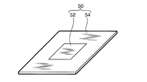
- FIG. 4 is a perspective view of a current control layer according to the present invention.
- FIG. 5 is a schematic longitudinal sectional view of a bipolar secondary battery showing variations regarding the arrangement of the current control layer.
- FIG. 6 is a schematic longitudinal sectional view of a bipolar secondary battery showing another variation regarding the arrangement of the current control layer.
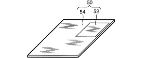
- FIG. 7 is a perspective view of a current control layer showing variations relating to the arrangement of temperature sensitive resistors according to the present invention.
- FIG. 8 is FIG.
- FIG. 7 is a schematic longitudinal sectional view of a bipolar secondary battery using 7 current control layers.
- FIG. FIG. 9 is a schematic longitudinal sectional view showing a bipolar secondary battery according to a second application example # of the present invention.
- FIG. 10A-10C are a front view, a rear view, and a longitudinal sectional view of the bipolar electrode.
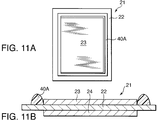
- FIG. 11A and 11B are a front view and a vertical view of a bipolar electrode in which a seal precursor is disposed.
- FIG. 12A and 12B are a front view and a cross-sectional view of a bipolar electrode in which separators are stacked.
- FIG. 13 is a schematic side view of a press machine for explaining the final formation process of the bipolar secondary battery.
- FIG. 14 is a schematic longitudinal sectional view of a bipolar secondary battery of Comparative Example # 1 having no current control layer.
- a bipolar secondary battery 100 includes a case 103 having a substantially rectangular cross section, and a positive current collector 101 and a negative current collector that are taken out from the inside of the case 103 through two opposite sides of the case 103. And an electric plate 102.
- the bipolar secondary battery 100 includes a battery body 300 inside the case 103.
- the battery body 300 is configured by connecting two stacked bodies 30 in which a plurality of cells 26 are stacked in series.
- the cell 26 is composed of, for example, a lithium ion cell.
- the positive electrode current collector plate 101 and the negative electrode current collector plate 102 are fixed to the inner peripheral surface of the case 103 so as to sandwich the battery body 300.
- the case 103 has a role of blocking the battery body 300 from outside air and protecting the battery body 300.
- the case 103 includes a pair of case members 103a and 103b. Case members 103a and 103b each have a recess for housing battery main body 300 and a flange portion surrounding the recess.
- the case 103 is integrally formed by welding the flange portions of the pair of case members 103a and 103b with the positive electrode current collecting plate 101 and the negative electrode current collecting plate 102 sandwiched between the inside and the outside of the case 103.
- a sheet-like material having strength that does not damage the laminated body 30 against a pressure difference generated inside and outside, and deformable flexibility is used. It is desirable that the sheet-like material does not allow permeation of the electrolytic solution or gas, has electrical insulation, and is chemically stable with respect to the material such as the electrolytic solution.
- a laminate film polyethylene, polypropylene, polycarbonate or the like is preferably used.
- the laminate film is obtained by coating a metal metal foil containing an alloy such as aluminum, stainless steel, nickel, or copper with an insulating synthetic resin film such as a polypropylene film.
- the cell 26 constituting the laminate 30 includes an electrolyte layer 25, a positive electrode active material layer 23 and a negative electrode active material layer 24 laminated on both sides of the electrolyte layer 25, and a positive electrode active material layer 23 and a negative electrode active material with respect to the lamination direction.
- the plate-like current collector 22 having a larger area laminated on the outside of the layer 24 is configured. However, when a plurality of cells 26 are stacked as shown in the figure, only one current collector 22 is sandwiched between adjacent cells 26.
- a known material is used for the current collector 22.
- aluminum or stainless steel (SUS) can be used.
- a polymer material may be included in the material of the current collector 22. That is, polyolefin (polypropylene, polyethylene), polyester (PET, PEN), polyimide, polyamide, and polyvinylidene fluoride (PVdF) can be used.
- PVdF polyvinylidene fluoride
- carbon such as ketjen black, acetylene black, carbon black, aluminum (Al), copper (Cu), stainless steel (SUS), Disperse particles of a metal such as titanium (Ti).
- the positive electrode active material layer 23 includes a positive electrode active material, and may further include a conductive additive or a binder.
- a composite oxide of a transition metal and lithium used in a solution-type lithium ion battery can be used.
- the negative electrode active material layer 24 includes a negative electrode active material, and may further include a conductive additive or a binder.
- a negative electrode active material used in a solution-type lithium ion battery can be used.
- the electrolyte layer 25 is composed of a layer containing a polymer having ion conductivity or a liquid electrolyte.
- a polymer gel electrolyte obtained by chemical crosslinking or physical crosslinking after impregnating a pregel solution into a separator as a base material is used as an electrolyte.
- the electrolytic solution contained in the electrolyte layer 25 contains an organic solvent such as polypropylene carbonate, ethylene carbonate, and diethyl carbonate, and boils and gasifies as the temperature rises.
- a polyethylene (PE) film is used as the separator, the melting point of the separator is 134 degrees Celsius (° C.). The boiling point of the electrolyte is 140 ° C.
- the electrolytic solution is applied to the surfaces of the positive electrode active material layer 23 and the negative electrode active material layer 24, and the separator is impregnated by superimposing the positive electrode active material layer 23 and the negative electrode active material layer 24 on the separator.
- FIG. 2 the detailed structure is omitted for easy understanding of the configuration of the battery body 300. Specifically, the illustration of the separator is omitted.
- the outer periphery of the cell 26 is covered with the seal portion 40.
- the seal portion 40 is filled between the outer peripheral portions of the adjacent current collectors 22 and blocks contact between the positive electrode active material layer 23, the electrolyte layer 25, and the outside air of the negative electrode active material layer 24.
- the seal part 40 seals the cell 26 to prevent a decrease in the ionic conductivity of the electrolyte.
- liquid or semi-solid gel electrolyte when a liquid or semi-solid gel electrolyte is used, liquid junction due to liquid leakage is prevented.
- seal precursor for example, a rubber-based resin that is in close contact with the current collector 22 by pressure deformation or a heat-sealable resin that is in close contact with the current collector 22 by heat-pressing and heat-sealing is used. Can do.
- the rubber resin is not particularly limited, but is preferably selected from the group consisting of silicon rubber, fluorine rubber, olefin rubber, and nitrile rubber. These rubber-based resins have excellent sealing properties, alkali resistance, chemical resistance, durability, weather resistance, heat resistance, etc., and maintain these excellent performance and quality for a long time even in the usage environment of secondary batteries. Can do.
- the resin that can be heat-sealed is preferably a resin that can exhibit an excellent sealing effect under any usage environment of the laminate 30.
- the heat-sealable resin is selected from the group consisting of silicon, epoxy, urethane, polybutadiene, olefin resin (polypropylene, polyethylene, etc.), and paraffin wax, for example. These heat-sealable resins have excellent sealing performance, alkali resistance, chemical resistance, durability / weather resistance, heat resistance, etc., and maintain excellent performance and quality for a long time even in the usage environment of secondary batteries. be able to.
- a plurality of bipolar electrodes 21 and an electrolyte layer 25 in which the positive electrode active material layer 23 is formed on one surface of the current collector 22 and the negative electrode active material layer 24 is formed on the other surface. are alternately stacked over 6 layers.
- Current collectors 22a and 22b are stacked on both ends of the stacked body 30 in the stacking direction. Unlike the current collector 22, the current collector 22a forms the positive electrode active material layer 23 on one surface and does not form anything on the other surface. In the current collector 22b, the negative electrode active material layer 24 is formed on one surface, and nothing is formed on the other surface.
- the current collector 22 a is laminated with the positive electrode active material layer 23 in contact with the electrolyte layer 25.
- the current collector 22 b is laminated with the negative electrode active material layer 24 in contact with the electrolyte layer 25.
- the current collector 22 a constitutes the positive electrode of the laminate 30, and the current collector 22 b constitutes the negative electrode of the laminate 30.
- the six cells 26 laminated as described above are hot-pressed using a hot press machine so that the seal portion 40 has a predetermined thickness, and the uncured seal portion 40 is cured, so that a bipolar type is obtained.
- the laminated body 30 is completed.
- the battery body 300 is arranged in series with the current control layer 50 sandwiched between the current collector 22a of one stacked body 30 and the current collector 22b of the other stacked body 30. It consists of two laminates 30. In this figure, the main part is drawn in a deformed manner for easy understanding of the features.
- the current control layer 50 includes a temperature-sensitive resistor 52 whose electric resistance increases as the temperature rises, and a current interrupting unit 54 having an electric resistance value higher than the resistance of the temperature-sensitive resistor 52 when the temperature rises. Become.
- the current interrupting part 54 is composed of a plate member with a high electrical resistance having the same outer dimensions as the adjacent current collector 22a and current collector 22b. A rectangular portion is cut out at the center of the current interrupting portion 54, and the temperature sensitive resistor 52 is fitted into the cutout portion.
- the temperature sensitive resistor 52 has the property of increasing the electrical resistance in response to a temperature rise.
- the current interrupting unit 54 has a larger electric resistance than the temperature sensitive resistor 52 when the temperature rises.
- the area of the temperature-sensitive resistor 52 fitted into the central portion of the current interrupting portion 54 is set to be smaller than the opposing surface of the positive electrode active material layer 23 and the negative electrode active material layer 24, that is, the electric reaction area. Therefore, the current density of the temperature sensitive resistor 52 during charging / discharging of the bipolar secondary battery 100 is higher than the current density in the stacked body 30. From the viewpoint of the characteristic of increasing electric resistance due to temperature rise, the area of the temperature-sensitive resistor 52 should be between 1/2 and 1/500 of the electric reaction area between the positive electrode active material layer 23 and the negative electrode active material layer 24. Is preferred.
- the temperature-sensitive resistor 52 and the current interrupting unit 54 electrically connect the current collector 22a of one adjacent laminate 30 and the current collector 22b of the other laminate 30 in parallel.
- the current interrupting unit 54 is made of a resin material that hardly allows current to flow, for example, a polyolefin such as polypropylene (PP) or polyethylene (PE), or polyester (PET).
- a polyolefin such as polypropylene (PP) or polyethylene (PE), or polyester (PET).
- the temperature-sensitive resistor 52 is formed of a positive temperature co-efficient (PTC) thermistor whose electric resistance increases as the temperature rises.
- the temperature sensitive resistor 52 has a glass transition point higher than that of the other components of the battery body 300 and starts to increase in electrical resistance at a temperature lower than the melting point of the other components or the boiling point of the electrolyte. Due to this characteristic, the temperature-sensitive resistor 52 can increase the electrical resistance before the components of the battery body 300 are damaged by the temperature rise, and can suppress the current flowing through the battery body 300.
- PTC positive temperature co-efficient
- polymer PTC polymer PTC, inorganic oxide PTC, or the like
- a conductive material dispersed in polypropylene (PP) or polyethylene (PE) polymer a conductive porous or mesh member, or a mesh made of PP polymer or PE polymer
- a nickel-shaped member coated with nickel (Ni) metal can be used.
- the current control layer 50 does not affect the charge / discharge performance of the bipolar secondary battery 100.
- PTC has a difference in electrical resistance increase start temperature depending on the type. By properly using the PTC, the increase start temperature of the electrical resistance can be arbitrarily set.
- the electric resistance change start temperature of the temperature sensitive resistor 52 is set to be lower than the lower one of the boiling point temperature of the electrolytic solution or the melting temperature of the separator. That is, it is set to 134 ° C. or lower. With this setting, it is possible to suppress the current flowing through the laminate 30 before the electrolytic solution boils and before the separator melts.
- the starting temperature of the change in electric resistance of the temperature-sensitive resistor 52 is set to a temperature 20 ° C. lower than the lower of the boiling point temperature of the electrolyte or the melting temperature of the separator, the temperature rise is accelerated by an excessive current. Even in such a situation, an overshoot of the temperature rise can be prevented.
- the temperature-sensitive resistor 52 it is also preferable to use a PTC element having a reversible characteristic with respect to temperature, in which the resistance increases as the temperature rises and the resistance decreases as the temperature falls.
- the temperature-sensitive resistor 52 composed of such a PTC element increases the resistance value when an excessive current flows and suppresses the current.
- the resistance value decreases and the current flows again. That is, the battery energy can be gradually released by repeatedly suppressing and canceling the current, in other words, by causing a hunting phenomenon.
- the use of a PTC element having reversible characteristics is not an essential requirement of the present invention. Even when an irreversible PTC element is used for the temperature sensitive resistor 52, the current flowing through the laminate 30 can be suppressed before the electrolytic solution boils and before the separator melts.
- the bipolar secondary battery 100 is formed by laminating the positive electrode current collector plate 101 and the negative electrode current collector plate 102 on both end faces of the battery body 300 in the stacking direction of the cells 26, and housing them in the case 103 as described above. Complete by vacuum-sealing.
- the bipolar secondary battery 100 used for an electric vehicle such as a hybrid electric vehicle (HEV) and an electric vehicle (EV)
- HEV hybrid electric vehicle
- EV electric vehicle
- Various electric circuits that operate may fail. When a current is supplied from the bipolar secondary battery 100 to the failed electric circuit, an excessive current continues to flow through the failed electric circuit, the circuit may generate heat, and a short circuit may occur in the high voltage line. It is also conceivable that the high-power line in the bipolar secondary battery 100 is short-circuited.
- the bipolar secondary battery 100 includes a temperature-sensitive resistor 52 having a smaller area than the electric reaction area between the positive electrode active material layer 23 and the negative electrode active material layer 24 between the stacked bodies 30.
- the current density flowing through the temperature sensitive resistor 52 is higher than that of the laminate 30. Therefore, when an excessive current flows in the bipolar secondary battery 100, the temperature-sensitive resistor 52 first self-heats. The subsequent temperature rise of the laminated body 30 promotes the temperature rise of the temperature sensitive resistor 52 held between the laminated bodies 30.
- the temperature sensitive resistor 52 increases the resistance value as the temperature rises. Therefore, before the temperature of the laminated body 30 reaches the upper limit temperature at which the battery function is stopped, the flow of the short-circuit current is suppressed by the temperature-sensitive resistor 52 having an increased resistance value. As a result, the excessive current is suppressed at an early stage, and the temperature increase of the battery main body 300 due to the excessive current can be prevented.
- the temperature-sensitive resistor 52 has a small area and is made of a material that increases resistance as soon as the temperature rises.
- the electric resistance of the temperature-sensitive resistor 52 during normal operation is small.
- the area of the temperature sensitive resistor 52 is preferably set in the range of 1/2 to 1/100 of the electric reaction area between the positive electrode active material layer 23 and the negative electrode active material layer 24.
- FIG. 5, 6 and 8 are FIG. In order to show the features in an easy-to-understand manner as in 3, the main part is drawn with deformation.
- FIG. 5 when the battery body 300 is composed of four stacked bodies 30, it is preferably between the second and third stacked bodies 30 counted from one end of the battery body 300, that is, the stacked body.
- the current control layer 50 is disposed in the middle portion of the battery body 300 with respect to the 30 stacking directions.
- FIG. 6 when the battery main body 300 is composed of four stacked bodies 30, the current control layer 50 is disposed between the first and second stacked bodies 30 counted from one end of the battery main body 300.
- the temperature sensitive resistor 52 is arranged at a position deviated from the center of the battery body 300 in the stacking direction of the cells 26. In that case, the temperature increase promoting action of the temperature-sensitive resistor 52 due to the temperature increase of the laminate 30 is shown in FIG. Although it is not obtained as much as the bipolar bipolar battery 100 of FIG. 5, such an arrangement is possible depending on the layout of the battery body 300.
- the temperature-sensitive resistor 52 can be provided not at the center of the current control layer 50 but at the corner of the current control layer 50.
- the temperature increase resistance of the temperature sensitive resistor 52 is promoted by the temperature rise of the laminate 30 as compared with the case where the temperature sensitive resistor 52 is provided at the center of the current control layer 50.
- such arrangement of the temperature-sensitive resistor 52 is also possible.
- the temperature sensitive resistor 52 responds to the temperature rise of the bipolar secondary battery 100. Increase electrical resistance. Thereby, the temperature rise of the battery main body 300 can be suppressed by interrupting or suppressing the current.
- the boiling point of the electrolytic solution and the melting of the separator can be prevented by setting the increase start temperature of the electric resistance of the temperature-sensitive resistor 52 to the lower one of the boiling point temperature of the electrolytic solution or the melting temperature of the separator.
- FIG. A second embodiment of the present invention will be described with reference to FIG. This figure also shows the main part deformed to show the features in an easy-to-understand manner.
- a current relaxation layer 56 having a resistance smaller than that of the bipolar electrode 21 is sandwiched between the current control layer 50 and the current collectors 22a and 22b.
- the current relaxation layer 56 is made of a metal foil or a metal plate such as aluminum (Al) or copper (Cu).
- the other structure of the bipolar secondary battery 100 is the same as that of the first embodiment.
- the current from the bipolar electrode 21 passes through the current relaxation layer 56 to the temperature sensitive resistor 52. Can be collected. That is, since the current relaxation layer 56 promotes current concentration on the temperature-sensitive resistor 52, self-heating of the temperature-sensitive resistor 52 can be promoted. The current concentration promoting action by the current relaxation layer 56 becomes more prominent as the resistance of the bipolar electrode 21 increases.
- FIG. 10A-10C, FIGS. 11A and 11B, FIG. 12A and 12B, FIG. 13, and FIG. 14 an experiment conducted by the inventors regarding the manufacture of the bipolar secondary battery 100 and the current suppression capability of the obtained product will be described.
- the positive electrode active material layer 23 was created in the following manner. That is, 85% by weight (wt%) of LiMn 2 O 4 as a positive electrode active material, 5 wt% of acetylene black as a conductive auxiliary agent, 10 wt% of polyvinylidene fluoride (PVdF) as a binder, and N-methylpyrodoline (NMP) as a slurry viscosity adjusting solvent ) was added until the viscosity became optimum for the coating operation to prepare a positive electrode slurry.
- PVdF polyvinylidene fluoride
- NMP N-methylpyrodoline
- a positive electrode slurry was applied to one side of a SUS foil having a thickness of 20 microns ( ⁇ m) as the current collector 22, and dried to form a positive electrode active material layer 23 having a thickness of 30 ⁇ m.
- the negative electrode active material layer 24 was created in the following manner. That is, 90 wt% of hard carbon as a negative electrode active material, 10 wt% of PVDF as a binder, and NMP as a slurry viscosity adjusting solvent were added until the viscosity became optimum for the coating operation to prepare a negative electrode slurry.
- a negative electrode slurry was applied to the surface of the current collector 22 opposite to the positive electrode active material layer 23 and dried to form a 30 ⁇ m negative electrode active material layer 24.
- the structure of the bipolar electrode 21 was obtained by forming the positive electrode active material layer 23 and the negative electrode active material layer 24 on both surfaces of the SUS foil as the current collector 22.
- the bipolar electrode 21 was cut to 160 ⁇ 130 millimeters (mm), and both the positive electrode and the negative electrode were peeled off by 10 mm in width to expose the surface of SUS. As a result, a bipolar electrode 21 having a 140 ⁇ 110 mm electrode surface and a current collector 22 made of SUS having a width of 10 mm exposed on the outer periphery thereof was produced.
- This bipolar electrode 21 is shown in FIG.
- the separator SP was impregnated with the electrolyte solution applied to the electrode surfaces of the positive electrode active material layer 23 and the negative electrode active material layer 24 by alternately overlapping the separator SP.
- region range corresponding to each electrode surface of the positive electrode active material layer 23 and the negative electrode active material layer 24 of separator SP.
- An electrolyte layer 25 was formed.
- a seal precursor 40A made of a one-component uncured epoxy resin was applied to the exposed portion of the SUS foil outside the positive electrode of the bipolar electrode 21 using a dispenser.
- a 170 ⁇ 140 (mm) separator SP made of a polyethylene (PE) film having a thickness of 12 ⁇ m and a melting point of 134 ° C. is applied to the positive electrode side so as to cover the entire surface of the current collector 22 containing SUS.
- PE polyethylene
- Example # 8 described below used a polyimide (PI) separator having a thickness of 15 ⁇ m and a melting point of 350 ° C. or higher.
- PI polyimide
- a seal precursor 40A made of a one-part uncured epoxy resin was applied using a dispenser at a position overlapping the seal precursor 40A of the separator SP.
- the separator SP penetrates the seal portion precursor 40A and protrudes outside the seal portion precursor 40A on the entire circumference.
- the protruding portion does not contact the positive electrode active material layer 23 and the negative electrode active material layer 24, and the electrolyte layer 25 is not formed at this portion.
- the electrolyte layer 25 is formed only in the region surrounded by the seal precursor 40A.
- FIG. 13 the structure of the laminated body 30 configured as described above is subjected to a surface pressure of 1 kilogram (kg) / square centimeter (cm2) ( ⁇ kilopascals) by a heat press with the current control layer 50 interposed therebetween. (KPa)) was subjected to hot pressing at 80 ° C. for 1 hour to cure the seal precursor 40A and obtain the seal portion 40. By this process, the seal portion 40 can be pressed to a predetermined thickness and can be further cured.
- the laminated body 30 in which 12 layers of the cells 26 were laminated by the above process was completed.
- FIG. 1 A PET plate having a thickness of 300 ⁇ m was cut into a size of 170 mm ⁇ 140 mm similar to the separator SP.
- FIG. A cutout with a size that allows the temperature-sensitive resistor 52 to fit is provided at a position corresponding to the central portion shown in FIG. Only the PET plate for Example # 13 to be described later is shown in FIG. As shown in FIG. 7, a cutout having a size for fitting the temperature-sensitive resistor 52 is provided at a position corresponding to the treatment portion of the current control layer 50.
- thermosensitive resistor 52 As the temperature-sensitive resistor 52, different polymer PTC sheets having temperatures of 140 ° C., 120 ° C., and 110 ° C. at which the resistance starts to increase sharply were cut into a predetermined area and used.
- the current relaxation layer 56 used in Example # 10 to be described later was created by cutting a 50 ⁇ m aluminum (Al) plate into 160 ⁇ 130 (mm).
- the two current relaxation layers 56 thus prepared were arranged so as to sandwich the current control layer 50 from both sides.
- the battery body 300 was obtained by sandwiching the current control layer 50 between any two of the two or four laminates 30 created by the above process via a conductive double-sided tape.
- Example 10 two current relaxation layers 56 are fixed to both surfaces of the current control layer 50 via a conductive double-sided tape, and are sandwiched between the two laminates 30 via a conductive double-sided tape.
- the battery body 300 of Examples # 1- # 13 was obtained.
- the positive electrode current collector plate 101 and the negative electrode current collector plate 102 were bonded to both ends of the battery main body 300 with a conductive double-sided tape.
- the surface of the positive electrode current collector plate 101 opposite to the battery main body 300 was bonded to the inner peripheral surface of the case member 103a with a double-sided tape.
- the flange portions were welded so that the case 103 was vacuum-sealed in such a manner that the flange portions of the case members 103a and 103b sandwich the take-out portion of the positive electrode current collector plate 101 and the negative electrode current collector plate 102.
- Example # 1- # 13 according to the present invention relating to the bipolar secondary battery 100 and Comparative Example # 1 not according to the present invention were completed.
- Example # 1- # 13 and Comparative Example # 1 are shown in TABLE-1.
- FIG. 14 in Comparative Example # 1 not according to the present invention, the two laminated bodies 30 were brought into direct contact without sandwiching the temperature-sensitive resistor 52.
- the battery body 300 is composed of two stacked bodies 30, the current control layer 50 is disposed between the two stacked bodies 30, and the temperature sensitive resistor is located at the center of the current control layer 50. 52 was placed.
- Example # 1 the area of the temperature-sensitive resistor 52 having a resistance increase start temperature of 140 ° C. was set to 2/3 of the electric reaction area between the positive electrode active material layer 23 and the negative electrode active material layer 24.
- Example # 2 the area of the temperature-sensitive resistor 52 having a resistance increase start temperature of 140 ° C. was set to 1 ⁇ 2 of the electric reaction area between the positive electrode active material layer 23 and the negative electrode active material layer 24.
- Example # 3 the area of the temperature-sensitive resistor 52 having a resistance increase start temperature of 140 ° C. was set to 1/5 of the electric reaction area between the positive electrode active material layer 23 and the negative electrode active material layer 24.
- Example # 4 the area of the temperature-sensitive resistor 52 having a resistance increase start temperature of 140 ° C. was set to 1/50 of the electric reaction area between the positive electrode active material layer 23 and the negative electrode active material layer 24.
- Example # 5 the area of the temperature-sensitive resistor 52 having a resistance increase start temperature of 140 ° C. was set to 1/100 of the electric reaction area between the positive electrode active material layer 23 and the negative electrode active material layer 24.
- Example # 6 the area of the temperature-sensitive resistor 52 having a resistance increase start temperature of 140 ° C. was set to 1/500 of the electric reaction area between the positive electrode active material layer 23 and the negative electrode active material layer 24. In this case, the resistance value of the temperature-sensitive resistor 52 during normal use of the bipolar secondary battery 100 was about 3/100 of the internal resistance of the multilayer body 30.
- Example # 7 the area of the temperature-sensitive resistor 52 having a resistance increase start temperature of 120 ° C. was set to 1/100 of the electric reaction area between the positive electrode active material layer 23 and the negative electrode active material layer 24.
- Example # 8 similarly to Example # 5, the area of the temperature-sensitive resistor 52 having a resistance increase start temperature of 140 ° C. is 1/100 of the electric reaction area between the positive electrode active material layer 23 and the negative electrode active material layer 24 of the laminate 30.
- a polyimide (PI) separator having a thickness of 15 ⁇ m and a melting point of 350 ° C. or higher was used as the separator SP.
- the separator SP of other examples and comparative example # 1 is made of polyethylene (PE) having a melting point of 134 ° C.
- Example # 9 a temperature-sensitive resistor 52 having a resistance increase start temperature of 110 ° C. was used, and the area of the temperature-sensitive resistor 52 was set to 1/100 of the electric reaction area between the positive electrode active material layer 23 and the negative electrode active material layer 24. .
- Example # 10 the current relaxation layer 56 created by the above-described process is replaced with FIG. As shown in FIG. 9, the current control layer 50 and the laminated body 30 on both sides were disposed.
- the battery body 300 is composed of the four laminated bodies 30.
- Example # 11 the area of the temperature-sensitive resistor 52 having a resistance increase start temperature of 120 ° C. was set to 1/100 of the electric reaction area between the positive electrode active material layer 23 and the negative electrode active material layer 24.
- FIG. 5 the current control layer 50 is arranged between the second and third stacked bodies 30 counted from one end of the battery body 300, that is, in the middle portion of the battery body 300 in the stacking direction of the stacked body 30. .
- Example # 12 a temperature-sensitive resistor 52 having a resistance increase start temperature of 120 ° C. was used, and the area of the temperature-sensitive resistor 52 was set to 1/100 of the electric reaction area between the positive electrode active material layer 23 and the negative electrode active material layer 24. .
- FIG. 6 the current control layer 50 is counted from one end of the battery body 300 in the stacking direction of the stacked body 30, and is separated from the first and second stacked bodies 30, that is, away from the middle portion of the battery body 300. Placed in position.
- Example # 13 a temperature-sensitive resistor 52 having a resistance increase start temperature of 120 ° C. was used, and the area of the temperature-sensitive resistor 52 was set to 1/100 of the electric reaction area between the positive electrode active material layer 23 and the negative electrode active material layer 24. . Further, the current control layer 50 is disposed between the second and third stacked bodies 30 counted from one end of the battery body 300 in the stacking direction of the stacked body 30, that is, in the middle portion of the battery body 300. On the other hand, FIG. As shown in FIGS. 7 and 8, the temperature-sensitive resistor 52 is disposed at the corner of the current control layer 50.
- Examples # 1- # 6 it can be seen that, as the area of the temperature-sensitive resistor 52 is reduced, the maximum temperature reached by the battery main body 300 decreases and the maximum temperature arrival time increases. In particular, when the area ratio of the temperature-sensitive resistor 52 to the electric reaction area between the positive electrode active material layer 23 and the negative electrode active material layer 24 is 1 ⁇ 2 or less, the maximum temperature reached by the battery body 300 is further reduced, and the maximum temperature arrival time is reduced. Significantly longer.
- the resistance of the current control layer 50 occupying the internal resistance of the multilayer body 30 becomes 3/100, and the multilayer body 30 in normal operation. Affects the output of. Therefore, the resistance occupied by the current control layer 50 is preferably 1/100 or more with respect to the internal resistance of the multilayer body 30.
- the temperature increase start temperature of each of the temperature sensitive resistors 52 is 140 ° C., which is equal to the boiling point 140 ° C. of the electrolyte and exceeds the melting point 134 ° C. of the separator SP. Therefore, although the current suppressing effect can be obtained, the maximum temperature reached is 215 ° C.-250 ° C., both exceeding the melting point of the separator SP and the boiling point of the electrolyte. For this reason, the melting of the separator SP and the boiling of the electrolytic solution cannot be completely prevented. As a result, some expansion deformation occurs in the battery body 300.
- Example # 7 the resistance increase start temperature 120 ° C. of the temperature-sensitive resistor 52 satisfies the condition that the lower temperature of the boiling point 140 ° C. of the electrolyte and the melting point 134 ° C. of the separator SP is equal to or lower.
- Example # 8 also satisfies the condition that the resistance increase start temperature 140 ° C. of the temperature-sensitive resistor 52 is equal to or lower than the lower one of the boiling point 140 ° C. of the electrolytic solution and the melting point 350 ° C. of the separator SP.
- the maximum temperature reached was suppressed to 140 ° C. or lower, which was the boiling point of the electrolytic solution, and deformation of the battery body 300 could be prevented.
- Example # 9 since the temperature increase start temperature of the temperature-sensitive resistor 52 is further lower, the maximum temperature reached is 115 ° C., which is lower than both the boiling point 140 ° C. of the electrolytic solution and the melting point 120 ° C. of the separator SP. And the melting of the separator SP could be prevented more reliably.
- the current relaxation layer 56 is disposed on both sides of the current control layer 50. Therefore, the current concentration on the temperature-sensitive resistor 52 is increased, and the maximum temperature reached is higher than in the example # 7. We were able to lower the maximum temperature reaching time.
- the current relaxation layer 56 is considered to be more effective as the resistance of the bipolar electrode 21 including the current collector 22, the positive electrode active material layer 23, and the negative electrode active material layer 24 increases.
- the present invention is not limited to a lithium ion battery but can be applied to any bipolar secondary battery.
- the present invention it is possible to block a large amount of current from flowing in the bipolar secondary battery. Therefore, it provides a favorable effect for protecting the secondary battery of the electric vehicle.
Landscapes
- Chemical & Material Sciences (AREA)
- Chemical Kinetics & Catalysis (AREA)
- Electrochemistry (AREA)
- General Chemical & Material Sciences (AREA)
- Engineering & Computer Science (AREA)
- Manufacturing & Machinery (AREA)
- Materials Engineering (AREA)
- Secondary Cells (AREA)
- Connection Of Batteries Or Terminals (AREA)
Abstract
Description


Claims (11)
- 複数の直列接続された積層体(30)を備え、各積層体(30)は電解質層を介して積層された、板状の集電体(22)と集電体(22)の一面に配置された正極活物質層(23)と集電体(22)のもう一面に配置された負極活物質層(24)とからなる複数の双極型電極(21)と、積層された複数の双極型電極(21)の積層方向の一端に形成された正極(22a)と、積層方向のもう一端に形成された負極(22b)と、を備え、
隣接するいずれか2つの積層体(30)の正極(22a)と負極(22b)との間に挟持された、温度上昇に応じて電気抵抗が増大する、正極活物質層(23)と負極活物質層(24)との電気反応エリアより面積が小さい感温抵抗(52)と、を備える双極型二次電池(100)。 - 感温抵抗(52)と、感温抵抗(52)と同一平面上に設けた感温抵抗(52)より大きな電気抵抗を有する電流遮断部(54)とからなる電流制御層(50)を、いずれか2つの積層体(30)の間に挟持した、請求項1の双極型二次電池(100)。
- 電解質層(25)は電解液を浸潤させたセパレータ(SP)で構成される、請求項1または2の双極型二次電池。
- 感温抵抗(52)が電気抵抗を増加させ始める抵抗増加始点温度は、電解液の沸点温度とセパレータ(SP)の溶融温度のうち低い方より低い温度に設定される、請求項3の双極型二次電池。
- 2つの積層体(30)と感温抵抗(52)との間に、集電体(22)、正極活物質層(23)及び負極活物質層(24)のいずれよりも電気抵抗の小さい電流緩和層(56)をそれぞれ挟持した、請求項3または4の双極型二次電池。
- 感温抵抗(52)の電気抵抗が増大を開始する抵抗増加始点温度は摂氏120-140度である、請求項1から5のいずれかの双極型二次電池。
- 双極型二次電池(100)の通常の充放電動作における感温抵抗(52)の抵抗値は、積層体(30)の電気抵抗の1/2から1/100である、請求項1から5のいずれかの双極型二次電池。
- 感温抵抗(52)は電気抵抗が温度に対して可逆的に変化するポジティブ・テンペラチャー・コエフィシェント・サーミスタで構成される、請求項1から7のいずれかの双極型二次電池。
- 直列に接続された3個以上の積層体(30)を備える、請求項1から8のいずれかの双極型二次電池。
- 感温抵抗(52)は集電体(22)の中央部に接して配置される、請求項1から9のいずれかの双極型二次電池(100)。
- 偶数個の直列に接続された積層体(30)を備え、感温抵抗(52)は積層体(30)の接続方向に関して偶数個の直列に接続された積層体(30)の中間位置に配置される、請求項1から10のいずれかの双極型二次電池(100)。
Priority Applications (4)
| Application Number | Priority Date | Filing Date | Title |
|---|---|---|---|
| US13/698,394 US8900734B2 (en) | 2010-05-19 | 2011-05-17 | Bipolar secondary battery |
| CN201180022462.8A CN102884655B (zh) | 2010-05-19 | 2011-05-17 | 双极型二次电池 |
| JP2012515890A JP5477467B2 (ja) | 2010-05-19 | 2011-05-17 | 双極型二次電池 |
| EP11783543.9A EP2573839B1 (en) | 2010-05-19 | 2011-05-17 | Bipolar secondary battery |
Applications Claiming Priority (2)
| Application Number | Priority Date | Filing Date | Title |
|---|---|---|---|
| JP2010115123 | 2010-05-19 | ||
| JP2010-115123 | 2010-05-19 |
Publications (1)
| Publication Number | Publication Date |
|---|---|
| WO2011145609A1 true WO2011145609A1 (ja) | 2011-11-24 |
Family
ID=44991711
Family Applications (1)
| Application Number | Title | Priority Date | Filing Date |
|---|---|---|---|
| PCT/JP2011/061301 Ceased WO2011145609A1 (ja) | 2010-05-19 | 2011-05-17 | 双極型二次電池 |
Country Status (5)
| Country | Link |
|---|---|
| US (1) | US8900734B2 (ja) |
| EP (1) | EP2573839B1 (ja) |
| JP (1) | JP5477467B2 (ja) |
| CN (1) | CN102884655B (ja) |
| WO (1) | WO2011145609A1 (ja) |
Cited By (3)
| Publication number | Priority date | Publication date | Assignee | Title |
|---|---|---|---|---|
| JP2015173569A (ja) * | 2014-03-12 | 2015-10-01 | 日立マクセル株式会社 | 予備充放電機能を有する電池パック |
| JP2018181524A (ja) * | 2017-04-07 | 2018-11-15 | トヨタ自動車株式会社 | 積層電池 |
| JP2025501421A (ja) * | 2022-01-07 | 2025-01-20 | ロシャー・ミヒャエル | バイポーラ電池積層体及びこのようなバイポーラ電池積層体を製造する方法 |
Families Citing this family (10)
| Publication number | Priority date | Publication date | Assignee | Title |
|---|---|---|---|---|
| US9720299B1 (en) * | 2015-01-12 | 2017-08-01 | Kinestral Technologies, Inc. | Electrochromic multi-layer devices with cross-linked ion conducting polymer |
| KR102065733B1 (ko) * | 2015-10-21 | 2020-01-13 | 주식회사 엘지화학 | 전극 복합체, 그를 포함하는 이차전지 및 케이블형 전지 이차전지 |
| WO2017149990A1 (ja) * | 2016-02-29 | 2017-09-08 | パナソニックIpマネジメント株式会社 | 積層型非水電解質二次電池 |
| WO2018158955A1 (ja) * | 2017-03-03 | 2018-09-07 | 日産自動車株式会社 | 二次電池および二次電池の制御方法 |
| CN107895761A (zh) * | 2017-11-13 | 2018-04-10 | 桑顿新能源科技有限公司 | 一种金属壳锂离子电池盖板 |
| JP6915567B2 (ja) * | 2018-02-28 | 2021-08-04 | 株式会社豊田自動織機 | 蓄電モジュール |
| JP6939685B2 (ja) | 2018-04-12 | 2021-09-22 | トヨタ自動車株式会社 | 積層電池 |
| CN110120545B (zh) * | 2019-05-13 | 2021-05-07 | 浙江锋锂新能源科技有限公司 | 一种非接触式混合固液电解质锂蓄电池及其制备方法 |
| CN115244759A (zh) | 2019-12-16 | 2022-10-25 | 戴森技术有限公司 | 具有内部膨胀消除和外部冷却特征的电池单元 |
| CN114335923B (zh) * | 2020-09-29 | 2025-09-16 | Sk新能源株式会社 | 接线端子保护盖及包括该接线端子保护盖的电池模块 |
Citations (5)
| Publication number | Priority date | Publication date | Assignee | Title |
|---|---|---|---|---|
| JPH07220755A (ja) * | 1994-02-07 | 1995-08-18 | Tdk Corp | 積層型リチウム二次電池 |
| JP2004178914A (ja) * | 2002-11-26 | 2004-06-24 | Nissan Motor Co Ltd | バイポーラ電極およびその電極を用いたバイポーラ二次電池 |
| JP2007173223A (ja) * | 2005-11-28 | 2007-07-05 | Nec Tokin Corp | 電池積層体および電池パック |
| JP2007299680A (ja) * | 2006-05-01 | 2007-11-15 | Nissan Motor Co Ltd | 双極型二次電池 |
| JP2009252548A (ja) | 2008-04-07 | 2009-10-29 | Toyota Motor Corp | 固体型電池 |
Family Cites Families (6)
| Publication number | Priority date | Publication date | Assignee | Title |
|---|---|---|---|---|
| DE60045183D1 (de) | 1999-05-17 | 2010-12-16 | Panasonic Corp | Schaltung und vorrichtung zum schutz einer sekundärbatterie |
| JP4472259B2 (ja) * | 2002-12-27 | 2010-06-02 | パナソニック株式会社 | 電気化学素子 |
| JP2004355953A (ja) * | 2003-05-29 | 2004-12-16 | Nissan Motor Co Ltd | バイポーラ二次電池およびバイポーラ二次電池容量調整システム |
| JP2005317468A (ja) * | 2004-04-30 | 2005-11-10 | Nissan Motor Co Ltd | バイポーラ電極、バイポーラ電極の製造方法、バイポーラ電池、組電池、およびこれらを搭載した車両 |
| US20100084161A1 (en) * | 2008-10-08 | 2010-04-08 | Robert A. Neal | Conductive film and process for making same |
| JP5341050B2 (ja) | 2010-11-08 | 2013-11-13 | オリンパス株式会社 | プリンタ装置及びプリンタ装置の画像形成方法 |
-
2011
- 2011-05-17 WO PCT/JP2011/061301 patent/WO2011145609A1/ja not_active Ceased
- 2011-05-17 JP JP2012515890A patent/JP5477467B2/ja active Active
- 2011-05-17 CN CN201180022462.8A patent/CN102884655B/zh active Active
- 2011-05-17 US US13/698,394 patent/US8900734B2/en active Active
- 2011-05-17 EP EP11783543.9A patent/EP2573839B1/en active Active
Patent Citations (5)
| Publication number | Priority date | Publication date | Assignee | Title |
|---|---|---|---|---|
| JPH07220755A (ja) * | 1994-02-07 | 1995-08-18 | Tdk Corp | 積層型リチウム二次電池 |
| JP2004178914A (ja) * | 2002-11-26 | 2004-06-24 | Nissan Motor Co Ltd | バイポーラ電極およびその電極を用いたバイポーラ二次電池 |
| JP2007173223A (ja) * | 2005-11-28 | 2007-07-05 | Nec Tokin Corp | 電池積層体および電池パック |
| JP2007299680A (ja) * | 2006-05-01 | 2007-11-15 | Nissan Motor Co Ltd | 双極型二次電池 |
| JP2009252548A (ja) | 2008-04-07 | 2009-10-29 | Toyota Motor Corp | 固体型電池 |
Non-Patent Citations (1)
| Title |
|---|
| See also references of EP2573839A4 |
Cited By (4)
| Publication number | Priority date | Publication date | Assignee | Title |
|---|---|---|---|---|
| JP2015173569A (ja) * | 2014-03-12 | 2015-10-01 | 日立マクセル株式会社 | 予備充放電機能を有する電池パック |
| JP2018181524A (ja) * | 2017-04-07 | 2018-11-15 | トヨタ自動車株式会社 | 積層電池 |
| JP2025501421A (ja) * | 2022-01-07 | 2025-01-20 | ロシャー・ミヒャエル | バイポーラ電池積層体及びこのようなバイポーラ電池積層体を製造する方法 |
| JP7727120B2 (ja) | 2022-01-07 | 2025-08-20 | ロシャー・ミヒャエル | バイポーラ電池積層体及びこのようなバイポーラ電池積層体を製造する方法 |
Also Published As
| Publication number | Publication date |
|---|---|
| US20130065097A1 (en) | 2013-03-14 |
| CN102884655A (zh) | 2013-01-16 |
| JPWO2011145609A1 (ja) | 2013-07-22 |
| JP5477467B2 (ja) | 2014-04-23 |
| US8900734B2 (en) | 2014-12-02 |
| EP2573839A4 (en) | 2017-01-11 |
| EP2573839A1 (en) | 2013-03-27 |
| EP2573839B1 (en) | 2017-09-13 |
| CN102884655B (zh) | 2015-01-21 |
Similar Documents
| Publication | Publication Date | Title |
|---|---|---|
| JP5477467B2 (ja) | 双極型二次電池 | |
| JP5459398B2 (ja) | 双極型二次電池 | |
| JP4661020B2 (ja) | バイポーラリチウムイオン二次電池 | |
| JP5186881B2 (ja) | バイポーラ電池 | |
| KR102488346B1 (ko) | 조전지 | |
| CN117638425A (zh) | 用于叠堆电池设计的集电器 | |
| EP1928050B1 (en) | Bipolar Battery and Battery Assembly | |
| JP2005276486A (ja) | 積層型電池、組電池および車両 | |
| WO2002071529A1 (en) | Nonaqueous electrolyte secondary battery and its producing method | |
| CN101425600A (zh) | 双极型二次电池、电池组及安装了这些电池的车辆 | |
| JP2004134210A (ja) | 積層型電池、組電池および車両 | |
| JP2011048932A (ja) | 双極型二次電池 | |
| WO2021131878A1 (ja) | 二次電池 | |
| KR20140012601A (ko) | 이차전지 및 이를 포함하는 전기화학소자 | |
| WO2013005523A1 (ja) | 組電池 | |
| JP5205713B2 (ja) | 双極型二次電池 | |
| JP4956777B2 (ja) | バイポーラ電池、組電池及びそれらの電池を搭載した車両 | |
| JP2011071044A (ja) | 双極型二次電池 | |
| JP6666096B2 (ja) | 蓄電デバイス | |
| JPH11265704A (ja) | 非水系電池および電極端子 | |
| JP2020140831A (ja) | 蓄電素子及び蓄電素子の製造方法 | |
| JP7194331B2 (ja) | ラミネート型電池 | |
| JP2002203524A (ja) | 非水電解質電池 | |
| JP2021039833A (ja) | 蓄電素子及び蓄電素子の製造方法 | |
| CN114583291A (zh) | 一种电芯配套用热响应安全单元及单体电池 |
Legal Events
| Date | Code | Title | Description |
|---|---|---|---|
| WWE | Wipo information: entry into national phase |
Ref document number: 201180022462.8 Country of ref document: CN |
|
| 121 | Ep: the epo has been informed by wipo that ep was designated in this application |
Ref document number: 11783543 Country of ref document: EP Kind code of ref document: A1 |
|
| WWE | Wipo information: entry into national phase |
Ref document number: 2012515890 Country of ref document: JP |
|
| REEP | Request for entry into the european phase |
Ref document number: 2011783543 Country of ref document: EP |
|
| WWE | Wipo information: entry into national phase |
Ref document number: 2011783543 Country of ref document: EP |
|
| WWE | Wipo information: entry into national phase |
Ref document number: 13698394 Country of ref document: US |
|
| NENP | Non-entry into the national phase |
Ref country code: DE |