WO2011148611A1 - ナビゲーション装置 - Google Patents
ナビゲーション装置 Download PDFInfo
- Publication number
- WO2011148611A1 WO2011148611A1 PCT/JP2011/002862 JP2011002862W WO2011148611A1 WO 2011148611 A1 WO2011148611 A1 WO 2011148611A1 JP 2011002862 W JP2011002862 W JP 2011002862W WO 2011148611 A1 WO2011148611 A1 WO 2011148611A1
- Authority
- WO
- WIPO (PCT)
- Prior art keywords
- road
- gradation
- route
- roads
- display
- Prior art date
- Legal status (The legal status is an assumption and is not a legal conclusion. Google has not performed a legal analysis and makes no representation as to the accuracy of the status listed.)
- Ceased
Links
Images














Classifications
-
- G—PHYSICS
- G01—MEASURING; TESTING
- G01C—MEASURING DISTANCES, LEVELS OR BEARINGS; SURVEYING; NAVIGATION; GYROSCOPIC INSTRUMENTS; PHOTOGRAMMETRY OR VIDEOGRAMMETRY
- G01C21/00—Navigation; Navigational instruments not provided for in groups G01C1/00 - G01C19/00
- G01C21/26—Navigation; Navigational instruments not provided for in groups G01C1/00 - G01C19/00 specially adapted for navigation in a road network
- G01C21/34—Route searching; Route guidance
- G01C21/36—Input/output arrangements for on-board computers
- G01C21/3667—Display of a road map
- G01C21/367—Details, e.g. road map scale, orientation, zooming, illumination, level of detail, scrolling of road map or positioning of current position marker
-
- G—PHYSICS
- G01—MEASURING; TESTING
- G01C—MEASURING DISTANCES, LEVELS OR BEARINGS; SURVEYING; NAVIGATION; GYROSCOPIC INSTRUMENTS; PHOTOGRAMMETRY OR VIDEOGRAMMETRY
- G01C21/00—Navigation; Navigational instruments not provided for in groups G01C1/00 - G01C19/00
- G01C21/26—Navigation; Navigational instruments not provided for in groups G01C1/00 - G01C19/00 specially adapted for navigation in a road network
- G01C21/34—Route searching; Route guidance
- G01C21/36—Input/output arrangements for on-board computers
- G01C21/3667—Display of a road map
- G01C21/3676—Overview of the route on the road map
-
- G—PHYSICS
- G08—SIGNALLING
- G08G—TRAFFIC CONTROL SYSTEMS
- G08G1/00—Traffic control systems for road vehicles
- G08G1/09—Arrangements for giving variable traffic instructions
- G08G1/0962—Arrangements for giving variable traffic instructions having an indicator mounted inside the vehicle, e.g. giving voice messages
- G08G1/0968—Systems involving transmission of navigation instructions to the vehicle
- G08G1/0969—Systems involving transmission of navigation instructions to the vehicle having a display in the form of a map
-
- G—PHYSICS
- G09—EDUCATION; CRYPTOGRAPHY; DISPLAY; ADVERTISING; SEALS
- G09B—EDUCATIONAL OR DEMONSTRATION APPLIANCES; APPLIANCES FOR TEACHING, OR COMMUNICATING WITH, THE BLIND, DEAF OR MUTE; MODELS; PLANETARIA; GLOBES; MAPS; DIAGRAMS
- G09B29/00—Maps; Plans; Charts; Diagrams, e.g. route diagram
- G09B29/003—Maps
- G09B29/006—Representation of non-cartographic information on maps, e.g. population distribution, wind direction, radiation levels, air and sea routes
- G09B29/007—Representation of non-cartographic information on maps, e.g. population distribution, wind direction, radiation levels, air and sea routes using computer methods
-
- G—PHYSICS
- G09—EDUCATION; CRYPTOGRAPHY; DISPLAY; ADVERTISING; SEALS
- G09B—EDUCATIONAL OR DEMONSTRATION APPLIANCES; APPLIANCES FOR TEACHING, OR COMMUNICATING WITH, THE BLIND, DEAF OR MUTE; MODELS; PLANETARIA; GLOBES; MAPS; DIAGRAMS
- G09B29/00—Maps; Plans; Charts; Diagrams, e.g. route diagram
- G09B29/10—Map spot or coordinate position indicators; Map reading aids
Definitions
- the present invention relates to a navigation device that displays a road that is connected to, intersects with, or is close to, a guide route as a guide route and a planned travel route, and changes the display form such as gradation position, gradation length, and contrast.
- the map display in the conventional navigation device displays all the roads that are unnecessary for route guidance uniformly, especially in areas with high road density, such as in the city center, so the entire screen becomes complicated and instantaneous visibility is remarkably improved. It was a factor to decrease.
- Patent Document 1 displays a tone-down display around the periphery except for a circle with a constant radius centered on the current location. In this case, both narrow streets and highways are toned down uniformly. The route to the facility of interest existing in a place exceeding a certain radius is not toned down.
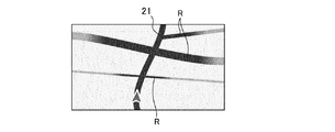
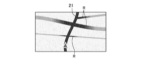
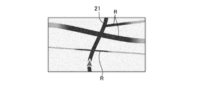
- this prior art simply lowers the contrast of roads that are connected, intersecting, or close to the guide route, so the road display blends into the background, making it difficult to see even major main roads on the map. It is difficult to recognize the surrounding roads momentarily while driving. For example, as shown in FIG. 40, even if a main road R having a larger number of lanes than the currently traveling guide route 21 intersects, the impression is the same as other narrow roads R, only displayed lightly on the map. May be displayed.
- reduce contrast refers to reducing road color saturation (making it closer to gray), reducing lightness (making it darker), and adjusting hue (making it closer to the background color). It refers to the technology that makes the display inconspicuous.
- the present invention displays a road that is connected to, intersects with, or is close to, a guide route as a guide route, a road to be traveled, and changes the display form.
- An object of the present invention is to provide a navigation device that can instantaneously visually recognize how the situation changes.
- a navigation device includes a guide route search unit that searches for a guide route from a current position to a destination, a planned travel route search unit that searches for a route that travels without searching for a guide route, a guide route, and a travel Connected, intersected, and close roads to the planned route, the guide route and the planned travel route from the predetermined distance inside the high contrast, outside the predetermined distance low contrast, the middle area between the inside and outside And a road periphery display changing unit that changes the gradation continuously or stepwise.
- roads connected to, intersecting with, or approaching a guide route have a high contrast inside a predetermined distance from the guide route and the planned travel route, and a low contrast outside the predetermined distance.
- a band-like portion of a certain range centering on the guide route and the planned travel route is displayed so as to float from the surroundings.
- FIG. 1 is a block diagram illustrating a configuration of a main part of a navigation device according to Embodiment 1.
- FIG. 3 is a flowchart for explaining the operation of the first embodiment.
- FIG. 6 is a process diagram of display by the operation of the first embodiment.
- FIG. 6 is a process diagram of display by the operation of the first embodiment.
- FIG. 6 is a process diagram of display by the operation of the first embodiment.
- It is a block diagram which shows the structure of the principal part of the navigation apparatus by Embodiment 2.
- FIG. 10 is a flowchart for explaining the operation of the second embodiment.
- FIG. 10 is a display process diagram according to the operation of the second embodiment.
- FIG. 10 is a display process diagram according to the operation of the second embodiment.
- FIG. 10 is a display process diagram according to the operation of the second embodiment.
- FIG. 10 is a display process diagram according to the operation of the second embodiment.
- FIG. 10 is a block diagram illustrating a configuration of a main part of a navigation device according to a third embodiment. 10 is a flowchart for explaining the operation of the third embodiment.
- FIG. 10 is a display process diagram according to the operation of the third embodiment.
- FIG. 10 is a display process diagram according to the operation of the third embodiment.
- FIG. 10 is a display process diagram according to the operation of the third embodiment.
- FIG. 10 is a display process diagram according to the operation of the third embodiment.
- FIG. 10 is a display process diagram according to the operation of the third embodiment.
- FIG. 10 is a flowchart for explaining the operation of the fourth embodiment.
- FIG. 10 is a block diagram illustrating a configuration of a main part of a navigation device according to a fifth embodiment. 10 is a flowchart for explaining the operation of the fifth embodiment. It is a block diagram which shows the structure of the principal part of the navigation apparatus by Embodiment 6.
- FIG. 18 is a flowchart for explaining the operation of the sixth embodiment. It is a block diagram which shows the structure of the principal part of the navigation apparatus by Embodiment 7.
- FIG. 18 is a flowchart for explaining the operation of the seventh embodiment.
- FIG. 12 is another process diagram of display according to the operation of the second embodiment.
- FIG. 12 is another process diagram of display according to the operation of the second embodiment.
- FIG. 12 is another process diagram of display according to the operation of the second embodiment.
- FIG. 12 is another process diagram of display according to the operation of the second embodiment.
- FIG. 12 is another process diagram of display according to the operation of the second embodiment.
- FIG. 38 is a process diagram of display by the operation of the seventh embodiment.
- FIG. 38 is a process diagram of display by the operation of the seventh embodiment.
- FIG. 38 is a process diagram of display by the operation of the seventh embodiment.
- FIG. 38 is a process diagram of display by the operation of the seventh embodiment.
- FIG. 38 is another display process diagram according to the operation in the eighth embodiment.
- FIG. 38 is another display process diagram according to the operation in the eighth embodiment.
- FIG. 38 is another display process diagram according to the operation in the eighth embodiment.
- FIG. 38 is another display process diagram according to the operation in the eighth embodiment.
- FIG. 38 is another display process diagram according to the operation in the eighth embodiment.
- FIG. 38 is another display process diagram according to the operation in the eighth embodiment.
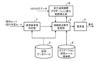
- FIG. 1 is a block diagram showing a configuration of a main part of the navigation device according to the first embodiment.
- a gradation processing rule storage unit 6 is provided.
- the guide route search unit 1 searches for a guide route 21 from the current location (departure point) to the destination, which is the same as the route search that has been conventionally performed.
- the planned travel route search unit 2 searches the planned travel route 21 that is assumed to continue traveling along the road that is currently traveling without searching for a guidance route.
- the road periphery display changing unit 3 inputs the guide route searched as described above, the planned traveling route 21 and the map information from the map database 5, and the gradation processing rule from the gradation processing rule storage unit 6, and the gradation position and gradation length. , Change the display mode such as contrast.
- step ST20 it is determined whether route guidance is being performed by the guidance route search unit 1 (step ST20). If NO, a planned travel route is created by the planned travel route search unit 2 (step ST21). Next, when the determination in step ST20 is YES and after the planned travel route is created in step ST21, the road periphery display changing unit 3 performs the processing operations of steps ST21 to ST27.
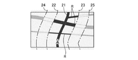
- the road periphery display changing unit 3 inputs map information from the map database 5 and selects a road R that is connected to, intersects with, and is close to the guidance route and the planned travel route 21 (step ST22). Then, with reference to the guide route and the planned travel route 21, a predetermined distance in the normal direction is maintained to the left and right of the route, and parallel virtual lines are drawn (step ST23). Two virtual lines are drawn to the left and right of the guide route and the planned travel route 21 (step ST24). As a result, as shown in FIG. 3, with reference to the guide route and the planned travel route 21, parallel imaginary lines 22 to 25 are drawn with a constant distance in the normal direction to the left and right.
- the distance between the guide route, the planned travel route 21 and the virtual lines 22, 23 corresponds to the first distance
- the distance between the guide route, the planned travel route 21 and the virtual lines 24, 25 is the first distance. Corresponds to a distance of two.
- the road periphery display changing unit 3 reads out the gradation processing rule stored in the gradation processing rule storage unit 6 and, as shown in FIG. 4, the connection belonging to the inside between the two virtual lines 22 and 23 on the inside.
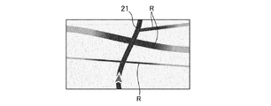
- the road R that intersects and is close is displayed at a normal density with high contrast as shown in FIG. 4 (step ST25). Further, the connections, intersections, and adjacent roads R that belong to the outside of the outer virtual lines 24 and 25 are displayed with low contrast as shown in FIG. 5 to create a visually inconspicuous expression (step ST26).
- connection, intersection, and adjacent road R belonging to the middle of the inner and outer virtual lines 22 and 24, 23 and 25 are gradually increased from the high contrast to the low contrast from the inside to the outside as shown in FIG. It is changed continuously or in multiple stages and displayed in a gradation (step ST27).
- the gradation process is preferably a continuous change in which the gradation difference is not as conspicuous as much as possible.
- the display unit 4 inputs the display signal from the road periphery display changing unit 3 processed as described above, and displays the road R connected to, intersecting with, and adjacent to the guidance route and the planned travel route 21 in a gradation. (Step ST28).
- the road R that is connected to, intersects with, and is close to the guide route and the planned travel route has a high contrast inside the predetermined distance from the guide route and the planned travel route.
- a belt-like part of a certain range centering on the guide route and the planned route by displaying the intermediate region between the inside and outside in a gradation in a continuous or stepwise manner with low contrast outside the predetermined distance. Appears to float from the surroundings. As a result, unnecessary surroundings are displayed with low contrast, and they are not noticeable more than necessary, and the line of sight centered on the high-contrast guide route and planned travel route is naturally determined and driving Even so, it is possible to instantly visually recognize where the vehicle travels and how the road conditions thereafter change.
- FIG. The second embodiment is a case in which the gradation change length is changed according to the importance (road type, number of lanes, road width) of the connection, intersection, and adjacent road R.
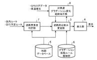
- FIG. 7 is a block diagram showing a configuration of a main part of the navigation device according to the second embodiment, in which a road importance degree determination unit 7 is provided on the input side of the road periphery display changing unit 3, and the other configuration is as shown in FIG. Since it is the same as the structure of the form 1, the same part is attached
- the guidance route search unit 1 and the planned travel route search unit 2 are not shown.
- step ST80 it is determined whether route guidance is being performed by the guidance route search unit 1 (step ST80). If NO, a planned travel route is created by the planned travel route search unit 2 (step ST81). Next, when the determination in step ST80 is YES and after the planned travel route is created in step ST81, the road periphery display changing unit 3 performs the processing operations of steps ST82 to ST88.
- the road periphery display changing unit 3 inputs map information from the map database 5 and selects a road R that is connected to, intersects with, and is close to the guidance route and the planned travel route 21 (step ST82). Then, the type and attribute of the selected road (highway, general road, national road, prefectural road, narrow street, etc.) are determined (step ST83).
- the width of the selected road R is determined (step ST84).
- the actual road width for each road R is calculated by referring to the lane number information for each road R in the map database 5 and the most detailed map database. This makes it possible to draw maps that are closer to the actual road conditions and easier to understand.
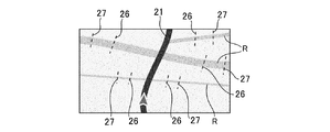
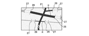
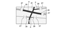
- the gradation start position 26 and gradation end position 27 are determined as shown in FIG. 9 in accordance with the importance of each selected road R (step ST85).
- the distance between the guide route / scheduled travel route 21 and the gradation start position 26 corresponds to the first distance
- the distance between the guide route / scheduled travel route 21 and the gradation end position 27 is the second distance. Corresponds to distance.
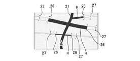
- connection, intersections, and adjacent roads R sandwiched between the left and right gradation start positions 26 are displayed with high contrast as shown in FIG. 10 (step ST86). Further, the connections, intersections, and roads R that are located outside the gradation end position 27 are displayed with low contrast as shown in FIG. 11 (step ST87).
- connection, intersection, and adjacent road R belonging to the middle of the gradation start position 26 and the end position 27 are gradually or gradually increased from the high contrast to the low contrast from the inside to the outside as shown in FIG. And displayed in gradation (step ST88).
- the gradation change length is set longer for roads with higher importance, roads with a large number of lanes, and roads with a wider road width.
- roads with high importance, roads with a large number of lanes, and roads with a wide road width are displayed clearly on the screen even when they are away from the route guidance route.
- gradation processing is performed at a short distance, so that it becomes familiar with the base color and is inconspicuous.
- the gradation process is preferably a continuous change in which the gradation difference is not as conspicuous as much as possible.
- the display unit 4 inputs the display signal from the road periphery display change unit 3 processed as described above, and displays the road R that is connected to, intersects with, and is adjacent to the guidance route and the planned traveling route 21 in a gradation (step). ST89).
- the scale of the road R can be inferred more intuitively as “long is the main road, and short is the narrow street”, making it easier to understand the surrounding road information.
- the main road is more prominent, and it is expected to increase the instantaneous visibility.
- the example which changes both a gradation start position and a gradation end position was demonstrated as an expansion / contraction method of a gradation change range, you may change only one. For example, as shown in FIG.
- the gradation start position 26 is moved closer to the guide route and the planned travel route 21 for the road R having a high degree of importance, as shown in FIG.
- the road R sandwiched between the left and right gradation start positions 26 is displayed with high contrast, and the road R belonging to the outside of the gradation end position 27 is displayed with low contrast as shown in FIG.
- the change range can be lengthened.
- FIG. Embodiment 3 is a case where the gradation change range of the connecting road is changed according to the traveling speed.
- FIG. 13 is a block diagram showing a configuration of a main part of the navigation device according to the third embodiment.
- a road importance degree determination unit 7 is provided on the input side of the road periphery display change unit 3 to input GPS log data and a vehicle speed signal.
- the vehicle speed gradation change range correction unit 8 is provided and connected to the road importance degree determination unit 7, and the other components are the same as those in the first embodiment. Description is omitted.
- the guide route search unit 1 and the planned travel route search unit 2 are not shown.
- step ST140 it is determined whether route guidance is being performed by the guidance route search unit 1 (step ST140). If NO, the planned travel route search unit 2 creates a planned travel route (step ST141). Next, when the determination in step ST140 is YES and after the planned travel route is created in step ST141, the road periphery display changing unit 3 performs the processing operations of steps ST142 to ST150.
- the road periphery display changing unit 3 inputs map information from the map database 5 and selects a road R that is connected to, intersects with, or is close to the guidance route and the planned travel route 21 (step ST142). Then, the type and attribute (highway, general road, national road, prefectural road, narrow street, etc.) of the selected road R are determined (step ST143).
- the width of the selected road R is determined (step ST144).
- the actual road width for each road R may be calculated by referring to the lane number information for each road R in the map database 5 or the most detailed map database. This makes it possible to draw maps that are closer to the actual road conditions and easier to understand.
- the vehicle speed gradation change range correction unit 8 detects the current travel speed from the GPS log data and the vehicle speed signal (step ST146), and between the gradation start position 26 and the gradation end position 27 according to the detected travel speed.
- the distance is shortened or extended (step ST147). In FIG. 16, the distance between the gradation start position 26 and the gradation end position 27 is shortened by bringing the gradation start position 26 closer to the guide route and the planned travel route 21 and the gradation end position 27 closer.
- connection, intersections, and adjacent roads R that are sandwiched between the left and right gradation start positions 26 are displayed with high contrast as shown in FIG. 10 (step ST 148).
- connection, intersection, and adjacent road R belonging to the outside of the gradation end position 27 are displayed with low contrast as shown in FIG. 11 (step ST149).
- connection, intersection, and adjacent road R belonging to the middle of the gradation start position 26 and the gradation end position 27 are gradually or continuously changed from the high contrast to the low contrast from the inside to the outside as shown in FIG. It is changed in multiple steps and displayed in gradation (step ST150).
- the display unit 4 inputs the display signal from the road periphery display change unit 3 processed as described above, and displays the road R that is connected to, intersects with, and is adjacent to the guidance route and the planned traveling route 21 in a gradation (step). ST151).
- the gradation change range of the connection, intersection, and adjacent road R is shortened as shown in FIG.
- the gradation change range is determined and displayed for each road scale based on 40 km / h.
- the gradation change length of the connection R, the intersection, and the road R adjacent to each other between the gradation start position 26 and the gradation end position 27 is determined to be 10% shorter as shown in FIG.
- the gradation change length is set to be 10% longer. That is, the slower the speed, the longer the gradation change length of the connection, intersection, and adjacent road R belonging to the middle of the gradation start position 26 and gradation end position 27, as shown in FIG. 18, and the surrounding detailed information is displayed easily.
- a highly safe screen display can be provided by shortening the gradation change range in order to reduce the amount of peripheral information.
- the gradation change range gradually changes according to the speed, it is possible to present the optimum amount of information according to the traveling speed at that time without feeling uncomfortable as if the screen display was suddenly changed. Become.
- the surrounding narrow road is also displayed with a long gradation width, It becomes easy to recognize the situation of a narrow road.
- the speed is high, the gradation change range of the surrounding roads is narrowed, and only the guide route is emphasized to improve instantaneous visibility and shorten the time for gazing, thereby contributing to safe driving.
- the surroundings are displayed in an easy-to-see manner as the vehicle speed decreases, making it easier to find a way out.
- FIG. 19 is a block diagram showing a configuration of a main part of the navigation device according to the fourth embodiment, which includes a traveling road scale change detecting unit 9 for inputting GPS log data and a traveling road scale gradation change range correcting unit 10. Since other configurations are the same as those of the second embodiment, the same parts are denoted by the same reference numerals, and redundant description is omitted.
- the guide route search unit 1 and the planned travel route search unit 2 are not shown.
- step ST200 it is determined whether route guidance is being performed by the guidance route search unit 1 (step ST200). If NO, the planned travel route search unit 2 creates a planned travel route (step ST201). Next, when the determination in step ST200 is YES and after the planned travel route is created in step ST201, the road periphery display changing unit 3 performs the processing operations of steps ST202 to ST210.
- the road periphery display changing unit 3 inputs map information from the map database 5, and selects a road R that is connected to, intersects with, or is close to the guidance route and the planned traveling route 21 (step ST202). Then, the type and attribute (highway, general road, national road, prefectural road, narrow street, etc.) of the selected road R are determined (step ST203).
- the width of the selected road R is determined (step ST204).
- the actual road width for each road R is calculated by referring to the lane number information for each road R in the map database 5 and the most detailed map database. This makes it possible to draw maps that are closer to the actual road conditions and easier to understand.
- the gradation start position 26 and gradation end position 27 are determined according to the importance of each road R (step ST205).
- the traveling road scale change detecting unit 9 detects the type of road and the width of the traveling road based on the GPS log data (step ST206), and the traveling road scale gradation change range correcting unit 10 receiving this detection signal is traveling. Extends or shortens the distance between gradation start position 26 and gradation end position 27 of road R connected to, intersecting, and approaching guide route 21 and planned travel route 21 according to the road scale (road type, number of lanes, road width) (Step ST207).
- connection, intersection, and adjacent road R belonging to the inside between the left and right gradation start positions 26 are displayed with high contrast as shown in FIG. 10 (step ST 208).
- connection, intersection, and adjacent road R belonging to the outside of the gradation end position 27 are displayed with low contrast as shown in FIG. 11 (step ST209).
- connection, intersection, and adjacent road R belonging to the middle of the gradation start position 26 and the end position 27 are gradually and continuously increased from the high contrast to the low contrast from the inside to the outside as shown in FIG. Or, it is changed in multiple steps and displayed in gradation (step ST210).
- the display unit 4 inputs the display signal from the road periphery display change unit 3 processed as described above, and displays the road R that is connected to, intersects with, and is adjacent to the guidance route and the planned traveling route 21 in a gradation (step). ST211).
- the traveling road R changes as follows according to the detected road scale (road type, number of lanes, road width).
- ⁇ When the currently running road R is determined to be an expressway. Only the road R connected to the high speed doorway on the traveling method side in the screen is detected and processed with a longer gradation change length. The other roads R are displayed with a constant low contrast display.
- ⁇ When the traveling road R is determined to be a large trunk road. For roads R of equal or larger size that are connected to, intersect with, or close to the guide route, planned route 21, processing with a longer gradation width, road R smaller than the traveling road R is processed with a shorter gradation width, Make it inconspicuous.
- ⁇ When the traveling road R is determined to be a narrow street.
- the gradation change length is set wider for the part near the current position to make it easier to see the details of the surrounding road conditions.
- the gradation change length is shortened as moving away from the current position. Note that the gradation change length is processed longer for main arterial roads and expressways. Alternatively, the image is displayed with a constant high contrast without performing gradation processing.
- the fourth embodiment by changing the gradation change range according to the scale of the road R that is currently running, only the road R having the same or larger scale can be obtained while traveling on a large highway.
- the equivalent road R maintains a long gradation change range, so that it is easy to understand the surrounding road connection situation.
- FIG. 21 is a block diagram showing a configuration of a main part of the navigation device according to the fifth embodiment, which is provided with a gradation change range correction unit 11 for the remaining distance to the guidance target intersection for inputting GPS log data. Since the configuration is the same as that of the second embodiment, the same parts are denoted by the same reference numerals, and redundant description is omitted. In FIG. 21, illustration of the guide route search unit 1 and the planned travel route search unit 2 is omitted.
- the road periphery display changing unit 3 inputs map information from the map database 5 and selects a road R that is connected to, intersects with, or is close to the guidance route and the planned travel route 21 (step ST220). Then, the type and attribute (highway, general road, national road, prefectural road, narrow street, etc.) of the selected road R are determined (step ST221).
- the width of the selected road R is determined (step ST222).
- the actual road width for each road R is calculated by referring to the lane number information for each road R in the map database 5 and the most detailed map database. This makes it possible to draw maps that are closer to the actual road conditions and easier to understand.
- the gradation start position 26 and the gradation end position 27 are determined according to the importance of each road R (step ST223).
- the gradation change range correction unit 11 selects the remaining distance to the next guidance target intersection based on the GPS log data (step ST224), and connects to the guidance route and the planned travel route 21 according to the selected remaining distance.
- the distance between the gradation start position 26 and the gradation end position 27 of the road R that intersects and approaches is extended or shortened (step ST225).
- connection, intersections, and adjacent roads R sandwiched between the left and right gradation start positions 26 are displayed with high contrast as shown in FIG. 10 (step ST 226).
- connection, intersection, and adjacent road R belonging to the outside of the gradation end position 27 are displayed with low contrast as shown in FIG. 11 (step ST227).
- the road R belonging to the middle of the gradation start position 26 and the end position 27 is gradually or continuously increased from the high contrast to the low contrast from the inside to the outside. It is changed stepwise and displayed in a gradation (step ST228).
- the display unit 4 inputs the display signal from the road periphery display change unit 3 processed as described above, and displays the road R that is connected to, intersects with, and is adjacent to the guidance route and the planned traveling route 21 in a gradation (step). ST229).
- the remaining distance to the next guidance target intersection is shortened, that is, the gradation change range of the road R connected to, intersecting, and approaching the guidance route is gradually lengthened as approaching the guidance intersection.
- the gradation change range By making the gradation change range longer, the road conditions around the guidance intersection are displayed in high contrast up to the detailed part, making it easier to grasp the surrounding road conditions.
- the gradation change range After passing the guidance intersection, the gradation change range is gradually shortened, and after a certain distance, the normal gradation change range is restored.
- the gradation change range of the road R connected to, intersecting and approaching the guidance route is gradually lengthened as the guidance intersection is approached, so that the surrounding road conditions can be easily grasped. Become.
- FIG. 23 is a block diagram showing the configuration of the main part of the navigation device according to the sixth embodiment, which is provided with a gradation change range correction unit 10 for each traveling road scale for inputting GPS log data. Since it is the same as the structure of the form 2, the same code
- step ST240 it is determined whether route guidance is being performed by the guide route search unit 1 (step ST240). If NO, a planned travel route is created by the planned travel route search unit 2 (step ST241). Next, when the determination in step ST240 is YES and after the planned travel route is created in step ST241, the road periphery display changing unit 3 performs the processing operations of steps ST242 to ST250.
- the road periphery display changing unit 3 inputs map information from the map database 5 and selects a road R that is connected to, intersects with, or is close to the guide route and the planned travel route 21 (step ST242). Then, the type and attribute (highway, general road, national road, prefectural road, narrow street, etc.) of the selected road R are determined (step ST243).
- the width of the selected road R is determined (step ST244).
- the actual road width for each road R is calculated by referring to the lane number information for each road R in the map database 5 and the most detailed map database. This makes it possible to draw maps that are closer to the actual road conditions and easier to understand.
- step ST245 it is determined whether the selected road R is a road R having a predetermined scale or less, that is, a predetermined type of road R (step ST245). If NO, the process proceeds to step ST246. A high-contrast display is performed on a road R of a certain scale or larger. If the determination in step ST245 is YES, the gradation start position 26 and the gradation end position 27 are determined according to the change in the scale of the currently traveling road and the importance of each road R (step ST247).
- connection, intersection, and adjacent road R that are sandwiched between the left and right gradation start positions 26 are displayed with high contrast as shown in FIG. 10 (step ST248).
- connections, intersections, and roads R that are located outside the gradation end position 27 are displayed with low contrast as shown in FIG. 11 (step ST249).
- the road R belonging to the middle of the gradation start position 26 and the end position 27 is gradually or continuously increased from the high contrast to the low contrast from the inside to the outside. It is changed stepwise and displayed in gradation (step ST250).
- the display unit 4 inputs the display signal from the road periphery display change unit 3 processed as described above, and displays the road R that is connected to, intersects with, and is adjacent to the guidance route and the planned traveling route 21 in a gradation (step). ST251).
- the gradation change range is defined for the surrounding roads based on the road scale, etc., and the display gradually reduces the contrast toward the periphery, but the gradation changes gradually during the time until it reaches the high-speed main line. Shorten the length and get on the high-speed main line. At the same time, all roads other than the high-speed main line are switched to low contrast display without gradation change.
- a road R having a predetermined size or larger (equivalent to or larger than a main trunk road, a highway, and a road that is currently running), that is, a predetermined size.
- the types of roads R are displayed with high contrast up to the periphery of the screen without gradation processing, and roads R of a certain size (one-way streets, narrow streets, etc.), that is, other types of roads R are guide routes
- roads R of a certain size one-way streets, narrow streets, etc.
- the gradation processing of the road R that is connected to, intersects with, or is adjacent to the road that is being driven is changed according to the change in the road size that is currently being driven, so that the display of the road R can be easily recognized as necessary.
- a navigation device that can be viewed more instantaneously can be obtained.
- FIG. 25 is a block diagram showing a configuration of a main part of the navigation device according to the seventh embodiment, in which a road periphery display change target exclusion unit 12 is provided on the input side of the road periphery display change unit 3, and the other configurations are as follows. Since it is the same as the structure of Embodiment 1, the same code
- step ST260 it is determined whether route guidance is being performed by the guidance route search unit 1 (step ST260). If NO, a planned travel route is created by the planned travel route search unit 2 (step ST261). Next, when the determination in step ST260 is YES and after the planned travel route is created in step ST261, the road periphery display changing unit 3 performs the processing operations of steps ST262 to ST270.
- the road periphery display changing unit 3 inputs map information from the map database 5 and selects a road R that is connected to, intersects with, and is close to the guidance route and the planned travel route 21 (step ST262). Then, the type and attribute (highway, general road, national road, prefectural road, narrow street, etc.) of the selected road R are determined (step ST263).
- the width of the selected road R is determined (step ST264).
- the actual road width for each road R is calculated by referring to the lane number information for each road R in the map database 5 and the most detailed map database. This makes it possible to draw maps that are closer to the actual road conditions and easier to understand.
- step ST265 it is determined whether the selected road R is an approachable road as viewed from the guidance route side. If NO, the process proceeds to step ST266, and the road that cannot be entered is uniformly displayed with a low contrast. If the determination in step ST265 is YES, the gradation start position 26 and gradation end position 27 are determined according to the importance of each road R (step ST267).
- connection, intersections, and adjacent roads R that are sandwiched between the left and right gradation start positions 26 are displayed with high contrast as shown in FIG. 10 (step ST 268).
- connections, intersections, and roads R that are located outside the gradation end position 27 are displayed with low contrast as shown in FIG. 11 (step ST269).
- the road R belonging to the middle of the gradation start position 26 and the end position 27 is gradually or continuously increased from the high contrast to the low contrast from the inside to the outside. It is changed stepwise and displayed in gradation (step ST270).
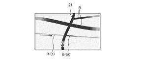
- the display unit 4 inputs the display signal from the road periphery display change unit 3 processed as described above, and displays the road R that is connected to, intersects with, and is adjacent to the guidance route and the planned traveling route 21 in a gradation (step). ST271). For example, as shown in FIG. 31, when a road R- (1) that cannot be entered is detected from the guide route and the planned travel route, the gradation is excluded from the road R- (1) as shown in FIG. Set the range. Next, as shown in FIG. 33, the road R (including the accessible road R- (2)) sandwiched between the left and right gradation start positions 26 is displayed with high contrast, and the gradation end position 27 is displayed as shown in FIG.
- the road R- (1) that cannot be entered is uniformly displayed with low contrast, and gradation processing is performed only on the road that can be entered. It can be determined whether or not it is possible to enter.
- the road R that cannot enter from the guide route side by one-way traffic is not subjected to gradation processing, and a constant low contrast display is performed regardless of the distance from the guide route.
- gradation processing As described above, according to the seventh embodiment, the road R that cannot enter from the guide route side by one-way traffic is not subjected to gradation processing, and a constant low contrast display is performed regardless of the distance from the guide route.
- Embodiment 8 FIG.
- the gradation start position and the gradation end position may be moved without changing the gradation change range. That is, the gradation change range may be moved.
- the gradation change range may be moved.
- the gradation change range may be moved.
- the gradation end position 27 is moved by the same distance in the direction away from the guide route and the travel route 21, as shown in FIG. 37, the range of the road R sandwiched between the left and right gradation start positions 26 displayed with high contrast is increased.
- the road R belonging to the outside of the gradation end position 27 is displayed with a low contrast, so that the gradation display between the gradation start position 26 and the gradation end position 27 is performed as shown in FIG. Can do.
- the gradation start position and gradation end position are moved in a direction to increase the display range with high contrast without changing the gradation change range. You can do it. According to this embodiment, the same effects as those of the second to sixth embodiments can be obtained.
- the navigation device can instantly visually recognize where the vehicle travels and how the road conditions thereafter change even during driving. Therefore, the present invention is suitable for use in a navigation device that displays a road that is connected to, intersects with, or is close to, a guide route as a guide route, a planned travel route, and changes the display form such as gradation position, gradation length, and contrast.
Landscapes
- Engineering & Computer Science (AREA)
- Remote Sensing (AREA)
- Physics & Mathematics (AREA)
- Radar, Positioning & Navigation (AREA)
- General Physics & Mathematics (AREA)
- Theoretical Computer Science (AREA)
- Business, Economics & Management (AREA)
- Educational Technology (AREA)
- Educational Administration (AREA)
- Mathematical Physics (AREA)
- Automation & Control Theory (AREA)
- Computer Hardware Design (AREA)
- General Engineering & Computer Science (AREA)
- Life Sciences & Earth Sciences (AREA)
- Ecology (AREA)
- Navigation (AREA)
Abstract
Description
実施の形態1.
実施の形態1は案内ルート、走行予定ルート21に接続、交差、近接する道路Rを、案内ルート、走行予定ルート21からの距離が離れるに従ってコントラストを徐々に下げる処理を行う場合である。図1は実施の形態1によるナビゲーション装置の要部の構成を示すブロック図であり、案内ルート探索部1、走行予定ルート探索部2、道路周辺表示変更部3、表示部4、地図データベース5、グラデーション処理ルール格納部6を備えている。
実施の形態2は、接続、交差、近接する道路Rの重要度(道路種別、車線数、道路幅)に応じてグラデーション変化長を変える場合である。図7は実施の形態2によるナビゲーション装置の要部の構成を示すブロック図であり、道路周辺表示変更部3の入力側に道路重要度判定部7を設けたもので、他の構成は実施の形態1の構成と同じであるので、同一部分には同一符号を付して重複説明を省略する。なお、図7には案内ルート探索部1、走行予定ルート探索部2の図示を省略している。
なお、グラデーション変化範囲の伸縮方法としては、グラデーション開始位置とグラデーション終了位置を共に変化させる例を説明したが、一方のみを変化させても良い。例えば、図27に示すように、重要度の高い道路Rについて、グラデーション開始位置26を図9の場合に比べて、案内ルート、走行予定ルート21に近づく方向に移動させ、図28に示すように左右のグラデーション開始位置26に挟まれた道路Rを高コントラストで表示し、図29に示すようにグラデーション終了位置27より外側に属する道路Rを低コントラスト表示することにより、図30に示すようにグラデーション変化範囲を長くすることができる。
実施の形態3は、走行速度に応じて接続道路のグラデーション変化範囲を変える場合である。図13は実施の形態3によるナビゲーション装置の要部の構成を示すブロック図であり、道路周辺表示変更部3の入力側に道路重要度判定部7を設け、GPSログデータ、車速信号を入力する対車速グラデーション変化範囲補正部8を設けて道路重要度判定部7と接続したもので、他の構成は実施の形態1の構成と同じであるので、同一部分には同一符号を付して重複説明を省略する。なお、図13には案内ルート探索部1、走行予定ルート探索部2の図示を省略している。
実施の形態4は、現在走行中の道路規模(道路種別、車線数、道路幅)に応じて接続道路のグラデーション変化長を変える場合である。図19は実施の形態4によるナビゲーション装置の要部の構成を示すブロック図であり、GPSログデータを入力する走行道路規模変更検出部9と走行道路規模グラデーション変化範囲補正部10を設けたもので、他の構成は実施の形態2の構成と同じであるので、同一部分には同一符号を付して重複説明を省略する。なお、図19には案内ルート探索部1、走行予定ルート探索部2の図示を省略している。
・現在走行中の道路Rが高速道路と判断した場合。
画面内にある進行方法側の高速出入り口と接続される道路Rのみ検出し長めのグラデーション変化長を持たせて処理。その他の道路Rは一定の低コントラスト表示とする。
・走行中道路Rが規模の大きな幹線道と判断した場合。
案内ルート、走行予定ルート21に接続、交差、近接する同等規模かそれ以上の道路Rに対し、長めのグラデーション幅で処理、走行中道路Rより規模の小さな道路Rは短いグラデーション幅で処理し、目立たなくさせる。
・走行中道路Rが細街路と判定した場合。
現在位置から近い部分はグラデーション変化長を広めに設定し、周辺の道路状況の詳細を見やすくする。現在位置から離れるにしたがってグラデーション変化長を短くする。
なお、主要幹線道路、高速道路等はグラデーション変化長をより長く処理する。あるいはグラデーション処理を行わず、一定の高コントラストで表示する。
実施の形態5は、経路案内走行時に案内交差点に接近する際に徐々に周辺道路のグラデーション変化範囲を変化させる場合である。図21は実施の形態5によるナビゲーション装置の要部の構成を示すブロック図であり、GPSログデータを入力する案内対象交差点までの残距離に対するグラデーション変化範囲補正部11を設けたもので、他の構成は実施の形態2の構成と同じであるので、同一部分には同一符号を付して重複説明を省略する。なお、図21には案内ルート探索部1、走行予定ルート探索部2の図示を省略している。
道路周辺表示変更部3は地図データベース5から地図情報を入力して、案内ルート、走行予定ルート21に接続、交差、近接する道路Rを選出する(ステップST220)。そして、選出された道路Rの種別、属性(高速道路、一般道路、国道、都道府県道、細街路等)を判断する(ステップST221)。
実施の形態6は、現在走行中の道路規模(道路種別、車線数、道路幅)に応じて接続道路のグラデーション変化範囲を変える場合である。図23は実施の形態6によるナビゲーション装置の要部の構成を示すブロック図であり、GPSログデータを入力する走行道路規模別グラデーション変化範囲補正部10を設けたもので、他の構成は実施の形態2の構成と同じであるので、同一部分には同一符号を付して重複説明を省略する。なお、図23には案内ルート探索部1、走行予定ルート探索部2の図示を省略している。
高速道路走行時においては、インターチェンジに接近し、徐々に走行スピードの低下が検出され、退出道路を走行し始めたと判断した場合、インターチェンジ付近の道路情報をより明確に表示するため、グラデーション変化長を徐々に長くなるように変化させる。高速道路から一般道に下りるまでの間の時間で、地図描画パターンを「高速道路走行地図描画パターン」から「一般道走行地図描画パターン」へ連続的に変化させる。これは経路案内時、非案内時いずれにも適用できる。
一般道を走行中、高速道路入り口から高速道路へと進入したと判断した場合、高速本線へ出るまでの間の時間で、地図描画パターンを「一般道走行地図描画パターン」から「高速道路走行地図描画パターン」へと連続的に変化させる。
実施の形態7は、進入不可能道路を除外する場合である。図25は実施の形態7によるナビゲーション装置の要部の構成を示すブロック図であり、道路周辺表示変更部3の入力側に道路周辺表示変更対象除外部12を設けたもので、他の構成は実施の形態1の構成と同じであるので、同一部分には同一符号を付して重複説明を省略する。なお、図25には案内ルート探索部1、走行予定ルート探索部2の図示を省略している。
上記実施の形態2から6においては、グラデーションの変化範囲を伸縮させる例を説明したが、グラデーション変化範囲は変えずに、グラデーション開始位置とグラデーション終了位置を移動させても良い。すなわち、グラデーション変化させる範囲を移動させても良い。例えば、接続、交差、近接する道路Rの重要度(道路種別、車線数、道路幅)が高い場合など、道路Rをより際立たせたい場合には、図36に示すようにグラデーション開始位置26とグラデーション終了位置27を案内ルート、走行ルート21から離れる方向に同じ距離だけ移動させると、図37に示すように高コントラストで表示する左右のグラデーション開始位置26に挟まれた道路Rの範囲を多くすることができ、図38に示すようにグラデーション終了位置27より外側に属する道路Rを低コントラスト表示することにより、図39に示すようにグラデーション開始位置26とグラデーション終了位置27の間をグラデーション表示することができる。その他、上記の実施の形態2から6において、グラデーション変化範囲を大きくすることに代えて、グラデーション変化範囲を変えずに高コントラストで表示する範囲を多くする方向にグラデーション開始位置とグラデーション終了位置を移動させれば良い。
この実施の形態によれば、上記実施の形態2から6と同様の効果を得ることができる。
Claims (12)
- 現在位置から目的地までの案内ルートを探索する案内ルート探索部と、前記案内ルートを探索することなく走行するルートを探索する走行予定ルート探索部と、前記案内ルート、前記走行予定ルートに接続、交差、近接する道路を地図データベースより選出し、選出した道路を、前記案内ルート、前記走行予定ルートから予め定めた第一の距離よりも内側は高コントラストに、前記第一の距離より長い第二の距離よりも外側は低コントラストに、この内側と外側の中間領域は連続的または段階的にグラデーション変化させる道路周辺表示変更部とを備えたナビゲーション装置。
- 選出した道路の重要度に応じてグラデーション変化させる範囲を伸縮することを特徴とする請求項1記載のナビゲーション装置。
- 走行速度に応じてグラデーション変化させる範囲を伸縮することを特徴とする請求項1記載のナビゲーション装置。
- 走行道路の種類、属性、規模に応じてグラデーション変化させる範囲を伸縮することを特徴とする請求項1記載のナビゲーション装置。
- 走行道路の種別が変化する場合、グラデーション変化させる範囲を予め定められた時間、あるいは距離内で徐々に変化させることを特徴とする請求項1記載のナビゲーション装置。
- 経路案内走行時における案内交差点に接近するに伴い、案内交差点までの残距離に応じてグラデーション変化させる範囲を伸縮することを特徴とする請求項1記載のナビゲーション装置。
- 案内ルート、走行予定ルートに接続、交差、近接する道路のうち、予め定めた種別の道路については表示形態処理を除外し、他の種別の道路については表示形態処理を行うことを特徴とする請求項1記載のナビゲーション装置。
- 案内ルート、走行予定ルートに接続、交差、近接する道路のうち、進入不可能道路は表示形態処理を除外し、残りの道路のみ表示形態処理を行うことを特徴とする請求項1記載のナビゲーション装置。
- 選出した道路の重要度に応じてグラデーション変化させる範囲を移動することを特徴とする請求項1記載のナビゲーション装置。
- 走行速度に応じてグラデーション変化させる範囲を移動することを特徴とする請求項1記載のナビゲーション装置。
- 走行道路の種類、属性、規模に応じてグラデーション変化させる範囲を移動することを特徴とする請求項1記載のナビゲーション装置。
- 経路案内走行時における案内交差点に接近するに伴い、案内交差点までの残距離に応じてグラデーション変化させる範囲を移動することを特徴とする請求項1記載のナビゲーション装置。
Priority Applications (4)
| Application Number | Priority Date | Filing Date | Title |
|---|---|---|---|
| CN201180012450.7A CN102782452B (zh) | 2010-05-24 | 2011-05-23 | 导航装置 |
| JP2012517130A JP5335139B2 (ja) | 2010-05-24 | 2011-05-23 | ナビゲーション装置 |
| EP11786314.2A EP2578998B1 (en) | 2010-05-24 | 2011-05-23 | Navigation system |
| US13/576,520 US9057623B2 (en) | 2010-05-24 | 2011-05-23 | Navigation device |
Applications Claiming Priority (2)
| Application Number | Priority Date | Filing Date | Title |
|---|---|---|---|
| JP2010-118439 | 2010-05-24 | ||
| JP2010118439 | 2010-05-24 |
Publications (1)
| Publication Number | Publication Date |
|---|---|
| WO2011148611A1 true WO2011148611A1 (ja) | 2011-12-01 |
Family
ID=45003611
Family Applications (1)
| Application Number | Title | Priority Date | Filing Date |
|---|---|---|---|
| PCT/JP2011/002862 Ceased WO2011148611A1 (ja) | 2010-05-24 | 2011-05-23 | ナビゲーション装置 |
Country Status (5)
| Country | Link |
|---|---|
| US (1) | US9057623B2 (ja) |
| EP (1) | EP2578998B1 (ja) |
| JP (1) | JP5335139B2 (ja) |
| CN (1) | CN102782452B (ja) |
| WO (1) | WO2011148611A1 (ja) |
Cited By (6)
| Publication number | Priority date | Publication date | Assignee | Title |
|---|---|---|---|---|
| JP2013122387A (ja) * | 2011-12-09 | 2013-06-20 | Denso Corp | ナビゲーション装置 |
| US20130325320A1 (en) * | 2012-06-05 | 2013-12-05 | At&T Intellectual Property I, L.P. | Navigation route updates |
| JP2014181914A (ja) * | 2013-03-18 | 2014-09-29 | Zenrin Datacom Co Ltd | 経路案内装置 |
| JP2017009618A (ja) * | 2016-08-30 | 2017-01-12 | 株式会社ゼンリンデータコム | 経路案内装置、経路案内用表示方法及びプログラム |
| JP2017181125A (ja) * | 2016-03-29 | 2017-10-05 | アイシン・エィ・ダブリュ株式会社 | 経路表示システムおよび経路表示プログラム |
| JP2023106418A (ja) * | 2022-01-06 | 2023-08-01 | 株式会社ユピテル | 表示装置 |
Families Citing this family (6)
| Publication number | Priority date | Publication date | Assignee | Title |
|---|---|---|---|---|
| WO2015118859A1 (ja) * | 2014-02-05 | 2015-08-13 | パナソニックIpマネジメント株式会社 | 車両用表示装置および車両用表示装置の表示方法 |
| CN109631934A (zh) * | 2018-12-21 | 2019-04-16 | 斑马网络技术有限公司 | 地图应用的信息处理方法、装置、服务器及储存介质 |
| CN110789533B (zh) * | 2019-09-25 | 2021-08-13 | 华为技术有限公司 | 一种数据呈现的方法及终端设备 |
| CN112747756B (zh) * | 2019-10-30 | 2023-04-07 | 北京地平线机器人技术研发有限公司 | 一种地图构建方法及装置 |
| DE112020006380T5 (de) * | 2019-12-27 | 2022-11-17 | Nippon Seiki Co., Ltd. | Navigationsvorrichtung, Steuerungsverfahren für die Navigationsvorrichtung, Steuerprogramm für die Navigationsvorrichtung |
| CN118984789A (zh) * | 2022-04-05 | 2024-11-19 | 日产自动车株式会社 | 信息提供装置及信息提供方法 |
Citations (6)
| Publication number | Priority date | Publication date | Assignee | Title |
|---|---|---|---|---|
| JPH09229692A (ja) * | 1996-02-26 | 1997-09-05 | Alpine Electron Inc | 地図描画方法 |
| JP2000214766A (ja) * | 1999-01-22 | 2000-08-04 | Fujitsu Ten Ltd | ナビゲ―ション装置 |
| WO2005020186A1 (ja) * | 2003-08-22 | 2005-03-03 | Hitachi, Ltd. | 地図表示方法 |
| JP2005274908A (ja) * | 2004-03-24 | 2005-10-06 | Xanavi Informatics Corp | 車載情報端末、要約地図作成装置、要約地図表示方法、表示制御装置 |
| JP2008157894A (ja) | 2006-12-26 | 2008-07-10 | Toyota Motor Corp | 運転支援装置 |
| WO2009084135A1 (ja) * | 2007-12-28 | 2009-07-09 | Mitsubishi Electric Corporation | ナビゲーション装置 |
Family Cites Families (11)
| Publication number | Priority date | Publication date | Assignee | Title |
|---|---|---|---|---|
| KR100256620B1 (ko) * | 1995-10-30 | 2000-05-15 | 모리 하루오 | 네비게이션장치 |
| JP4326070B2 (ja) | 1999-05-19 | 2009-09-02 | ソニーマニュファクチュアリングシステムズ株式会社 | 測定装置 |
| JP2000329566A (ja) * | 1999-05-21 | 2000-11-30 | Nec Microcomputer Technology Ltd | カーナビゲーションシステムおよび画面表示方法 |
| JP2003057045A (ja) | 2001-08-15 | 2003-02-26 | Sony Corp | 地図表示方法及び地図表示装置並びに地図表示システム |
| JP2004317418A (ja) * | 2003-04-18 | 2004-11-11 | Denso Corp | 車両用地図表示装置 |
| JP2005156480A (ja) * | 2003-11-28 | 2005-06-16 | Sony Corp | 情報提供装置 |
| JP2007121001A (ja) | 2005-10-26 | 2007-05-17 | Matsushita Electric Ind Co Ltd | ナビゲーション装置 |
| JP2008051538A (ja) * | 2006-08-22 | 2008-03-06 | Xanavi Informatics Corp | 車載地図表示装置 |
| JP5364237B2 (ja) | 2006-08-28 | 2013-12-11 | ダイセルポリマー株式会社 | めっき樹脂成形体 |
| JP2009250933A (ja) * | 2008-04-10 | 2009-10-29 | Toyota Motor Corp | 車両用ナビゲーション装置 |
| CN101476895B (zh) * | 2009-01-20 | 2011-06-15 | 深圳市凯立德欣软件技术有限公司 | 显示道路相交处的方法、道路相交处绘制模块和导航系统 |
-
2011
- 2011-05-23 WO PCT/JP2011/002862 patent/WO2011148611A1/ja not_active Ceased
- 2011-05-23 EP EP11786314.2A patent/EP2578998B1/en not_active Not-in-force
- 2011-05-23 JP JP2012517130A patent/JP5335139B2/ja not_active Expired - Fee Related
- 2011-05-23 US US13/576,520 patent/US9057623B2/en active Active
- 2011-05-23 CN CN201180012450.7A patent/CN102782452B/zh not_active Expired - Fee Related
Patent Citations (6)
| Publication number | Priority date | Publication date | Assignee | Title |
|---|---|---|---|---|
| JPH09229692A (ja) * | 1996-02-26 | 1997-09-05 | Alpine Electron Inc | 地図描画方法 |
| JP2000214766A (ja) * | 1999-01-22 | 2000-08-04 | Fujitsu Ten Ltd | ナビゲ―ション装置 |
| WO2005020186A1 (ja) * | 2003-08-22 | 2005-03-03 | Hitachi, Ltd. | 地図表示方法 |
| JP2005274908A (ja) * | 2004-03-24 | 2005-10-06 | Xanavi Informatics Corp | 車載情報端末、要約地図作成装置、要約地図表示方法、表示制御装置 |
| JP2008157894A (ja) | 2006-12-26 | 2008-07-10 | Toyota Motor Corp | 運転支援装置 |
| WO2009084135A1 (ja) * | 2007-12-28 | 2009-07-09 | Mitsubishi Electric Corporation | ナビゲーション装置 |
Cited By (9)
| Publication number | Priority date | Publication date | Assignee | Title |
|---|---|---|---|---|
| JP2013122387A (ja) * | 2011-12-09 | 2013-06-20 | Denso Corp | ナビゲーション装置 |
| US20130325320A1 (en) * | 2012-06-05 | 2013-12-05 | At&T Intellectual Property I, L.P. | Navigation route updates |
| US8825374B2 (en) * | 2012-06-05 | 2014-09-02 | At&T Intellectual Property I, L.P. | Navigation route updates |
| US9664525B2 (en) | 2012-06-05 | 2017-05-30 | At&T Intellectual Property I, L.P. | Navigation route updates |
| JP2014181914A (ja) * | 2013-03-18 | 2014-09-29 | Zenrin Datacom Co Ltd | 経路案内装置 |
| JP2017181125A (ja) * | 2016-03-29 | 2017-10-05 | アイシン・エィ・ダブリュ株式会社 | 経路表示システムおよび経路表示プログラム |
| JP2017009618A (ja) * | 2016-08-30 | 2017-01-12 | 株式会社ゼンリンデータコム | 経路案内装置、経路案内用表示方法及びプログラム |
| JP2023106418A (ja) * | 2022-01-06 | 2023-08-01 | 株式会社ユピテル | 表示装置 |
| JP7634898B2 (ja) | 2022-01-06 | 2025-02-25 | 株式会社ユピテル | 表示装置 |
Also Published As
| Publication number | Publication date |
|---|---|
| EP2578998B1 (en) | 2018-10-24 |
| JPWO2011148611A1 (ja) | 2013-07-25 |
| US20120323487A1 (en) | 2012-12-20 |
| CN102782452B (zh) | 2016-01-20 |
| JP5335139B2 (ja) | 2013-11-06 |
| EP2578998A4 (en) | 2015-01-07 |
| US9057623B2 (en) | 2015-06-16 |
| EP2578998A1 (en) | 2013-04-10 |
| CN102782452A (zh) | 2012-11-14 |
Similar Documents
| Publication | Publication Date | Title |
|---|---|---|
| JP5335139B2 (ja) | ナビゲーション装置 | |
| CN100573624C (zh) | 地图显示方法 | |
| US7835861B2 (en) | Navigation apparatuses, methods, and programs for generation of a 3D movie | |
| US10088323B2 (en) | Navigation device | |
| JP2004286559A (ja) | 車両用ナビゲーションシステムおよび経路案内方法 | |
| US9304011B2 (en) | Map display device | |
| JP2008249683A (ja) | 自動車ナビゲーションシステムの交差点案内方法 | |
| JP2009042219A (ja) | ナビゲーション装置及びナビゲーションプログラム | |
| JP6446784B2 (ja) | ナビゲーション装置 | |
| JP5355705B2 (ja) | 地図描画装置 | |
| JP2653282B2 (ja) | 車両用道路情報表示装置 | |
| JP2010091582A (ja) | ナビゲーション装置及びコンピュータプログラム | |
| JP4736714B2 (ja) | ナビゲーション装置 | |
| JP2912119B2 (ja) | ナビゲーション装置 | |
| JP2007178209A (ja) | 地図表示装置 | |
| JP2006023127A (ja) | ナビゲーション装置と関心地点情報提示方法 | |
| JP3471459B2 (ja) | 車載用ナビゲーション装置 | |
| JPH04232811A (ja) | ナビゲ−ションにおける経路探索方法 | |
| JP2007333654A (ja) | ナビゲーション装置 | |
| JP4818943B2 (ja) | ナビゲーション装置 | |
| KR20040022742A (ko) | 차량 네비게이션 시스템의 도로정보 표시방법 및 그 장치 | |
| JP2004317327A (ja) | ナビゲーション装置並びに該装置用プログラム及び記録媒体 | |
| JPH06294661A (ja) | 車載用ナビゲーション装置 | |
| JPH087527B2 (ja) | 最適経路決定装置 | |
| JPH08210869A (ja) | 車両用現在位置表示装置 |
Legal Events
| Date | Code | Title | Description |
|---|---|---|---|
| WWE | Wipo information: entry into national phase |
Ref document number: 201180012450.7 Country of ref document: CN |
|
| 121 | Ep: the epo has been informed by wipo that ep was designated in this application |
Ref document number: 11786314 Country of ref document: EP Kind code of ref document: A1 |
|
| WWE | Wipo information: entry into national phase |
Ref document number: 2012517130 Country of ref document: JP |
|
| WWE | Wipo information: entry into national phase |
Ref document number: 13576520 Country of ref document: US |
|
| WWE | Wipo information: entry into national phase |
Ref document number: 2011786314 Country of ref document: EP |
|
| NENP | Non-entry into the national phase |
Ref country code: DE |