WO2011148810A1 - 復帰制御システム - Google Patents
復帰制御システム Download PDFInfo
- Publication number
- WO2011148810A1 WO2011148810A1 PCT/JP2011/061213 JP2011061213W WO2011148810A1 WO 2011148810 A1 WO2011148810 A1 WO 2011148810A1 JP 2011061213 W JP2011061213 W JP 2011061213W WO 2011148810 A1 WO2011148810 A1 WO 2011148810A1
- Authority
- WO
- WIPO (PCT)
- Prior art keywords
- urea water
- dosing valve
- urea
- valve
- return control
- Prior art date
- Legal status (The legal status is an assumption and is not a legal conclusion. Google has not performed a legal analysis and makes no representation as to the accuracy of the status listed.)
- Ceased
Links
Images


Classifications
-
- F—MECHANICAL ENGINEERING; LIGHTING; HEATING; WEAPONS; BLASTING
- F01—MACHINES OR ENGINES IN GENERAL; ENGINE PLANTS IN GENERAL; STEAM ENGINES
- F01N—GAS-FLOW SILENCERS OR EXHAUST APPARATUS FOR MACHINES OR ENGINES IN GENERAL; GAS-FLOW SILENCERS OR EXHAUST APPARATUS FOR INTERNAL-COMBUSTION ENGINES
- F01N11/00—Monitoring or diagnostic devices for exhaust-gas treatment apparatus
-
- F—MECHANICAL ENGINEERING; LIGHTING; HEATING; WEAPONS; BLASTING
- F01—MACHINES OR ENGINES IN GENERAL; ENGINE PLANTS IN GENERAL; STEAM ENGINES
- F01N—GAS-FLOW SILENCERS OR EXHAUST APPARATUS FOR MACHINES OR ENGINES IN GENERAL; GAS-FLOW SILENCERS OR EXHAUST APPARATUS FOR INTERNAL-COMBUSTION ENGINES
- F01N3/00—Exhaust or silencing apparatus having means for purifying, rendering innocuous, or otherwise treating exhaust
- F01N3/08—Exhaust or silencing apparatus having means for purifying, rendering innocuous, or otherwise treating exhaust for rendering innocuous
- F01N3/10—Exhaust or silencing apparatus having means for purifying, rendering innocuous, or otherwise treating exhaust for rendering innocuous by thermal or catalytic conversion of noxious components of exhaust
- F01N3/18—Exhaust or silencing apparatus having means for purifying, rendering innocuous, or otherwise treating exhaust for rendering innocuous by thermal or catalytic conversion of noxious components of exhaust characterised by methods of operation; Control
- F01N3/20—Exhaust or silencing apparatus having means for purifying, rendering innocuous, or otherwise treating exhaust for rendering innocuous by thermal or catalytic conversion of noxious components of exhaust characterised by methods of operation; Control specially adapted for catalytic conversion
- F01N3/206—Adding periodically or continuously substances to exhaust gases for promoting purification, e.g. catalytic material in liquid form, NOx reducing agents
- F01N3/208—Control of selective catalytic reduction [SCR], e.g. by adjusting the dosing of reducing agent
-
- B—PERFORMING OPERATIONS; TRANSPORTING
- B01—PHYSICAL OR CHEMICAL PROCESSES OR APPARATUS IN GENERAL
- B01D—SEPARATION
- B01D2251/00—Reactants
- B01D2251/20—Reductants
- B01D2251/206—Ammonium compounds
- B01D2251/2067—Urea
-
- F—MECHANICAL ENGINEERING; LIGHTING; HEATING; WEAPONS; BLASTING
- F01—MACHINES OR ENGINES IN GENERAL; ENGINE PLANTS IN GENERAL; STEAM ENGINES
- F01N—GAS-FLOW SILENCERS OR EXHAUST APPARATUS FOR MACHINES OR ENGINES IN GENERAL; GAS-FLOW SILENCERS OR EXHAUST APPARATUS FOR INTERNAL-COMBUSTION ENGINES
- F01N2550/00—Monitoring or diagnosing the deterioration of exhaust systems
- F01N2550/05—Systems for adding substances into exhaust
-
- F—MECHANICAL ENGINEERING; LIGHTING; HEATING; WEAPONS; BLASTING
- F01—MACHINES OR ENGINES IN GENERAL; ENGINE PLANTS IN GENERAL; STEAM ENGINES
- F01N—GAS-FLOW SILENCERS OR EXHAUST APPARATUS FOR MACHINES OR ENGINES IN GENERAL; GAS-FLOW SILENCERS OR EXHAUST APPARATUS FOR INTERNAL-COMBUSTION ENGINES
- F01N2610/00—Adding substances to exhaust gases
- F01N2610/02—Adding substances to exhaust gases the substance being ammonia or urea
-
- F—MECHANICAL ENGINEERING; LIGHTING; HEATING; WEAPONS; BLASTING
- F01—MACHINES OR ENGINES IN GENERAL; ENGINE PLANTS IN GENERAL; STEAM ENGINES
- F01N—GAS-FLOW SILENCERS OR EXHAUST APPARATUS FOR MACHINES OR ENGINES IN GENERAL; GAS-FLOW SILENCERS OR EXHAUST APPARATUS FOR INTERNAL-COMBUSTION ENGINES
- F01N2610/00—Adding substances to exhaust gases
- F01N2610/14—Arrangements for the supply of substances, e.g. conduits
- F01N2610/1453—Sprayers or atomisers; Arrangement thereof in the exhaust apparatus
-
- F—MECHANICAL ENGINEERING; LIGHTING; HEATING; WEAPONS; BLASTING
- F01—MACHINES OR ENGINES IN GENERAL; ENGINE PLANTS IN GENERAL; STEAM ENGINES
- F01N—GAS-FLOW SILENCERS OR EXHAUST APPARATUS FOR MACHINES OR ENGINES IN GENERAL; GAS-FLOW SILENCERS OR EXHAUST APPARATUS FOR INTERNAL-COMBUSTION ENGINES
- F01N2610/00—Adding substances to exhaust gases
- F01N2610/14—Arrangements for the supply of substances, e.g. conduits
- F01N2610/1493—Purging the reducing agent out of the conduits or nozzle
-
- Y—GENERAL TAGGING OF NEW TECHNOLOGICAL DEVELOPMENTS; GENERAL TAGGING OF CROSS-SECTIONAL TECHNOLOGIES SPANNING OVER SEVERAL SECTIONS OF THE IPC; TECHNICAL SUBJECTS COVERED BY FORMER USPC CROSS-REFERENCE ART COLLECTIONS [XRACs] AND DIGESTS
- Y02—TECHNOLOGIES OR APPLICATIONS FOR MITIGATION OR ADAPTATION AGAINST CLIMATE CHANGE
- Y02A—TECHNOLOGIES FOR ADAPTATION TO CLIMATE CHANGE
- Y02A50/00—TECHNOLOGIES FOR ADAPTATION TO CLIMATE CHANGE in human health protection, e.g. against extreme weather
- Y02A50/20—Air quality improvement or preservation, e.g. vehicle emission control or emission reduction by using catalytic converters
-
- Y—GENERAL TAGGING OF NEW TECHNOLOGICAL DEVELOPMENTS; GENERAL TAGGING OF CROSS-SECTIONAL TECHNOLOGIES SPANNING OVER SEVERAL SECTIONS OF THE IPC; TECHNICAL SUBJECTS COVERED BY FORMER USPC CROSS-REFERENCE ART COLLECTIONS [XRACs] AND DIGESTS
- Y02—TECHNOLOGIES OR APPLICATIONS FOR MITIGATION OR ADAPTATION AGAINST CLIMATE CHANGE
- Y02T—CLIMATE CHANGE MITIGATION TECHNOLOGIES RELATED TO TRANSPORTATION
- Y02T10/00—Road transport of goods or passengers
- Y02T10/10—Internal combustion engine [ICE] based vehicles
- Y02T10/12—Improving ICE efficiencies
Definitions
- the present invention relates to a return control system for solving a malfunction of a dosing valve and a blockage of a liquid supply line through which urea water is supplied, and returning to a normal state.
- An SCR system using an SCR (Selective Catalytic Reduction) device has been developed as an exhaust gas purification system for purifying NO x in exhaust gas of a diesel engine.
- This SCR system supplies urea water stored in a urea tank upstream of the exhaust gas of the SCR, generates ammonia by the heat of the exhaust gas, and reduces and purifies NO x on the SCR catalyst by this ammonia. (For example, see Patent Document 1).
- urea water is injected from a dosing valve (urea injection device, dosing module) provided on the upstream side of the SCR device.
- a dosing valve urea injection device, dosing module
- the dosing valve 104 has a nozzle 127 provided in a cylinder 127 filled with high-pressure urea water, and a valve body 129 that closes the nozzle 128 is attached to a cylindrical plunger 130 having a slit 133.
- the structure is such that the valve body 129 is separated from the injection port 128 and the urea water is injected by pulling up the plunger 130 by energizing the coil 131.
- a spring 132 is provided inside the dosing valve 104 to urge the valve element 129 to a normally closed state via the plunger 130, when the energization of the coil 131 is stopped, the plunger force is generated by the spring force. Since 130 is pulled down and the valve body 129 closes the nozzle 128, the injection of urea water is stopped.
- the urea water is supplied from the urea tank to the dosing valve 104 by a supply module including an SM pump and a urea water pressure sensor.
- a supply module including an SM pump and a urea water pressure sensor.
- the urea tank and the supply module are connected by a liquid supply line, and urea water sucked up from the urea tank through the liquid supply line is dosed via a pressure supply line connecting the supply module and the dosing valve 104.
- Supply to valve 104 Supply to valve 104.
- feedback control is performed so that the pressure of urea water in the dosing valve 104 (measured value of the urea water pressure sensor of the supply module) is constant, and injection of urea water is started when the pressure becomes constant. It has become.
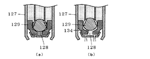
- the dosing valve 104 Since the dosing valve 104 is provided in the exhaust pipe of the engine through which high-temperature exhaust gas flows, when the dosing valve 104 becomes high temperature, the urea water in the dosing valve 104 also becomes high temperature, and as shown in FIG.
- the urea water in the valve 104 is crystallized and the valve body 129 is fixed, or as shown in FIG. 8B, the solid 134 in which urea water is crystallized is the valve seat of the valve body 129 and the cylinder 127. Between them, the urea water injection cannot be stopped, and the dosing valve 104 malfunctions and proper urea water injection control cannot be performed.
- an object of the present invention is to provide a return control system for resolving the malfunction of the dosing valve and the blockage of the liquid supply line through which the urea water is supplied and returning it to the normal state.
- the invention of claim 1 includes a dosing valve that injects urea water into the exhaust pipe, and urea water in the urea tank by sucking up urea water in the urea tank. And a supply module for returning the urea water in the dosing valve to the urea tank.
- the dosing valve opens and closes the cylinder filled with the urea water and the valve body of the cylinder and is normally closed.
- This is a return control system that consists of a plunger and a coil that operates the plunger, and returns to the normal state when the dosing valve does not operate normally. It monitors the dosing valve and detects an abnormality in the dosing valve. When the abnormality detection unit detects abnormality of the dosing valve by the abnormality detection unit, To return the urea water to the urea tank, a return control system characterized by comprising a return control unit for controlling the supply module.
- the invention according to claim 2 is a supply valve for injecting urea water into the exhaust pipe, and supplying the urea water in the urea tank by sucking the urea water in the urea tank and returning the urea water in the dosing valve to the urea tank.
- the urea tank and the supply module are connected by a liquid supply line, and when the liquid supply line is closed, a return control system for returning to a normal state, the dosing valve Pressure abnormality detection means for detecting an abnormality in the urea water pressure from the measured value of the urea water pressure sensor that measures the pressure of the supplied urea water, and when the abnormality in the urea water pressure is detected by the pressure abnormality detection means, And a return control means for controlling the supply module to return the urea water in the line to the urea tank. It is.
- the malfunction of the dosing valve and the blockage of the liquid feeding line through which the urea water is fed can be solved, and the normal state can be restored.
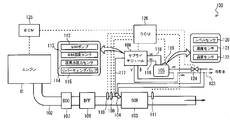
- an SCR system 100 includes an SCR device 103 provided in an exhaust pipe 102 of an engine E, and a dosing valve (urea that injects urea water upstream of the SCR device 103 (upstream of exhaust gas).
- a dosing valve urea that injects urea water upstream of the SCR device 103 (upstream of exhaust gas).
- injection device, dosing module 104, urea tank 105 for storing urea water, supply module 106 for supplying urea water stored in urea tank 105 to dosing valve 104, dosing valve 104, supply module 106, etc.
- DCU Dosing Control Unit
- a DOC (Diesel Oxidation Catalyst) 107, a DPF (Diesel Particulate Filter) 108, and an SCR device 103 are sequentially arranged from the upstream side to the downstream side of the exhaust gas.
- the DOC 107 is for oxidizing NO in the exhaust gas exhausted from the engine E into NO 2 and controlling the ratio of NO and NO 2 in the exhaust gas to increase the denitration efficiency in the SCR device 103.
- the DPF 108 is for collecting PM (Particulate Matter) in the exhaust gas.
- a dosing valve 104 is provided in the exhaust pipe 102 on the upstream side of the SCR device 103. As described with reference to FIG. 7, the dosing valve 104 is attached to a cylindrical plunger 130 having a nozzle 128 provided in a cylinder 127 filled with high-pressure urea water, and a valve body 129 that closes the nozzle 128 having a slit 133. In this structure, the valve body 129 is separated from the injection port 128 and the urea water is injected by pulling up the plunger 130 by energizing the coil 131.
- a spring 132 is provided inside the dosing valve 104 to urge the valve element 129 to a normally closed state via the plunger 130, when the energization of the coil 131 is stopped, the plunger force is generated by the spring force. Since 130 is pulled down and the valve body 129 closes the nozzle 128, the injection of urea water is stopped.
- the exhaust pipe 102 on the upstream side of the dosing valve 104 is provided with an exhaust temperature sensor 109 that measures the temperature of the exhaust gas at the inlet of the SCR device 103 (SCR inlet temperature).
- An upstream NO x sensor 110 that detects the NO x concentration on the upstream side of the SCR device 103 is provided upstream of the SCR device 103 (here, upstream of the exhaust temperature sensor 109).
- a downstream side NO x sensor 111 that detects the NO x concentration on the downstream side of the SCR device 103 is provided on the downstream side.
- the supply module 106 includes an SM pump 112 that pumps urea water, an SM temperature sensor 113 that measures the temperature of the supply module 106 (the temperature of urea water flowing through the supply module 106), and the pressure of urea water in the supply module 106 (
- the urea water pressure sensor 114 for measuring the pressure on the discharge side of the SM pump 112 and the urea water flow path are switched to supply urea water from the urea tank 105 to the dosing valve 104 or within the dosing valve 104.
- a reverting valve 115 for switching whether to return the urea water to the urea tank 105.
- the reverting valve 115 when the reverting valve 115 is OFF, the urea water from the urea tank 105 is supplied to the dosing valve 104, and when the reverting valve 115 is ON, the urea water in the dosing valve 104 is supplied to the urea tank 105. I tried to return it.
- the supply module 106 uses the SM pump 112 to supply the urea water in the urea tank 105 to a liquid supply line (suction line) 116. And the excess urea water is returned to the urea tank 105 through a recovery line (back line) 118.
- the reverting valve 115 When the key is OFF (ignition OFF, vehicle stop), the reverting valve 115 is switched so that the urea water in the dosing valve 104 is returned to the urea tank 105, and the dosing valve 104 is crystallized by urea water crystallization. The occurrence of malfunction is prevented. As described above, control for returning the urea water in the dosing valve 104 to the urea tank 105 is referred to as “empting” in this specification.
- the dosing valve 104 When performing the opening, the dosing valve 104 is opened in advance, and the urea water in the dosing valve 104 is returned to the urea tank 105, so that the exhaust gas (air) in the exhaust pipe 102 is passed from the dosing valve 104 to the urea tank 105. I'm trying to inhale.
- the urea tank 105 is provided with an SCR sensor 119.
- the SCR sensor 119 includes a level sensor 120 that measures the level (level) of urea water in the urea tank 105, a temperature sensor 121 that measures the temperature of urea water in the urea tank 105, and a sensor in the urea tank 105. And a quality sensor 122 for measuring the quality of the urea water.
- the quality sensor 122 detects the quality of the urea water in the urea tank 105 by detecting, for example, the concentration of urea water and whether or not a different mixture is mixed in the urea water from the propagation speed and electrical conductivity of the ultrasonic waves. To do.
- a cooling line 123 for circulating cooling water for cooling the engine E is connected to the urea tank 105 and the supply module 106.
- the cooling line 123 is configured to exchange heat between the cooling water passing through the urea tank 105 and flowing through the cooling line 123 and the urea water in the urea tank 105.
- the cooling line 123 passes through the supply module 106 and exchanges heat between the cooling water flowing through the cooling line 123 and the urea water in the supply module 106.
- the cooling line 123 is provided with a tank heater valve (coolant valve) 124 for switching whether or not to supply cooling water to the urea tank 105 and the supply module 106. Although the cooling line 123 is also connected to the dosing valve 104, the dosing valve 104 is configured to be supplied with cooling water regardless of whether the tank heater valve 124 is opened or closed. 1, the cooling line 123 is disposed along the liquid feeding line 116, the pressure feeding line 117, and the recovery line 118 through which the urea water passes.
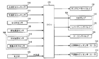
- FIG. 2 shows an input / output configuration diagram of the DCU 126.
- the DCU126 upstream-side NO x sensor 110, the downstream-side NO x sensor 111, SCR sensor 119 (the level sensor 120, temperature sensor 121, the quality sensor 122), the exhaust gas temperature sensor 109, the supply module 106
- the SM temperature sensor 113, the urea water pressure sensor 114, and an input signal line from an ECM (Engine Control Module) 125 that controls the engine E are connected. From the ECM 125, signals of outside air temperature and engine parameters (engine speed, etc.) are input.
- the DCU126, tank heater valve 124, SM pump 112 and reverting valve 115 of the supply module 106, the dosing valve 104, the heater of the upstream-side NO x sensor 110, the output signal to the heater, the downstream-side NO x sensor 111 The lines are connected. Note that the input / output of signals between the DCU 126 and each member may be input / output via individual signal lines or input / output via a CAN (Controller Area Network).
- CAN Controller Area Network
- DCU126 includes a signal of the engine parameters from ECM125, based on the exhaust gas temperature from the exhaust temperature sensor 109, thereby estimating the amount of the NO x in the exhaust gas, the amount of the NO x in the exhaust gas estimated is adapted to determine the urea water injected from the dosing valve 104 based on, further, when injected with urea water was determined by dosing valve 104, controls the dosing valve 104 based on the detection value of the upstream-side NO x sensor 110 Thus, the amount of urea water injected from the dosing valve 104 is adjusted.
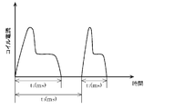
- the dosing valve 104 injects urea water by energizing for t 1 every t 0 (fixed). This t 1 changes according to the urea injection amount. In the case of the opening, the energization is maintained for a predetermined time. The predetermined time is a time for returning the urea water in the pipe to the urea tank 105.
- the urea water in the dosing valve 104 is heated and crystallized by the high temperature exhaust gas, and is fixed when the dosing valve 104 does not operate normally.
- a return control system is provided.
- the return control system is mounted on the DCU 126 and includes an abnormality detection unit for the dosing valve 104 and a return control unit.
- the abnormality detection means is configured to detect an abnormality depending on whether the opening / closing operation of the dosing valve 104 is normal.
- the return control means is configured to control the supply module 106 to return the urea water in the dosing valve 104 to the urea tank 105 when the abnormality detecting means detects an abnormality of the dosing valve 104. Specifically, the return control means opens the dosing valve 104, switches the reverting valve 115 of the supply module 106, operates the SM pump 112, and forcibly performs emptying (forced emptying). Composed.
- the return control system repeats the following operations.
- the abnormality detection means detects whether or not the dosing valve 104 is abnormal (S401).
- the return control means opens the dosing valve 104, switches the reverting valve 115 of the supply module 106, operates the SM pump 112, and performs forced emptying.
- the urea water crystallized together with the urea water can be removed by the force of returning the urea water in the dosing valve 104 to the urea tank 105. If the crystallized urea water cannot be removed (the dosing valve 104 remains closed without moving), the urea water cannot be returned or supplied, and the urea water remains in the dosing valve 104. By repeatedly forcing and supplying urea water and changing the pressure applied to the urea water in the dosing valve 104, the urea water can be sent to the position of the crystallized urea water to dissolve and remove the crystals. .
- the malfunction of the dosing valve 104 can be eliminated. If the malfunction of the dosing valve 104 cannot be resolved even after repeating S401, 402 to 404 and repeating the forced emptying and urea water supply a predetermined number of times, the dosing valve 104 may be determined to be faulty. . Thereby, it is possible to determine whether the fault is recoverable or non-recoverable, and it is possible to prevent a situation in which the driver is warned of the fault in spite of the recoverable fault.
- the dosing valve 104 is opened in advance, and the exhaust gas (air) in the exhaust pipe 102 is sucked from the dosing valve 104 to the urea tank 105. That is, when the emptying is performed, exhaust gas is sucked through the liquid feeding line 116, the pressure feeding line 117, and the like. For this reason, it is possible to remove foreign substances accumulated in the liquid feed line 116 and the pressure feed line 117.
- the return control system includes pressure abnormality detection means for detecting a urea water pressure abnormality from the measured value of the urea water pressure sensor 114 that measures the pressure of the urea water supplied to the dosing valve 104. It may be provided that when the abnormality of the pressure of the urea water is detected by the pressure abnormality detecting means, the forcible emptying may be performed by the return control means. That is, as shown in FIG. 5, the pressure abnormality detecting means detects whether or not the pressure of the urea water supplied to the dosing valve 104 is abnormal (whether it is constant) (S501), and the pressure abnormality is detected in S501. May be forcibly executed by the return control means (S502).
- the SM pump 112 may be turned off without operating the reverting valve 115.
Landscapes
- Engineering & Computer Science (AREA)
- Chemical & Material Sciences (AREA)
- Chemical Kinetics & Catalysis (AREA)
- Combustion & Propulsion (AREA)
- Mechanical Engineering (AREA)
- General Engineering & Computer Science (AREA)
- Health & Medical Sciences (AREA)
- Toxicology (AREA)
- Exhaust Gas After Treatment (AREA)
- Exhaust Gas Treatment By Means Of Catalyst (AREA)
Abstract
ドージングバルブの作動不良や、尿素水が送液される送液ラインの閉塞を解消し、正常な状態に復帰させるための復帰制御システムを提供する。 ドージングバルブ104が正常に作動しないときに正常な状態に復帰させるための復帰制御システムであって、ドージングバルブ104の異常を検出する異常検出手段と、異常検出手段でドージングバルブ104の異常を検出したときに、ドージングバルブ104内の尿素水を尿素タンク105に戻すべく、サプライモジュール106を制御する復帰制御手段とを備える復帰制御システムである。
Description
本発明は、ドージングバルブの作動不良や、尿素水が送液される送液ラインの閉塞を解消し、正常な状態に復帰させるための復帰制御システムに関するものである。
ディーゼルエンジンの排気ガス中のNOxを浄化するための排ガス浄化システムとして、SCR(Selective Catalytic Reduction)装置を用いたSCRシステムが開発されている。
このSCRシステムは、尿素タンクに貯留された尿素水をSCRの排気ガス上流に供給し、排気ガスの熱でアンモニアを生成し、このアンモニアによって、SCR触媒上でNOxを還元して浄化するものである(例えば、特許文献1参照)。
ここで、尿素水からアンモニアが生成される過程を図6を用いて説明する。
図6に示すように、尿素水は、沸点以上の温度になると、その水分が蒸発を開始し、融解物を経てガスが生成される。生成されたガスは、温度を上昇させると結晶化し、固形物が生成される。生成された固形物は昇華するとアンモニアが生成される。また、生成された融解物やガスの一部は水蒸気と共に加水分解して、アンモニアと炭酸ガスが生成される。
ところで、尿素水は、SCR装置の上流側に設けられたドージングバルブ(尿素噴射装置、ドージングモジュール)から噴射される。
図7に示すように、ドージングバルブ104は、高圧の尿素水が満たされたシリンダ127に噴口128が設けられ、その噴口128を塞ぐ弁体129がスリット133を有する筒状のプランジャ130に取り付けられた構造となっており、コイル131に通電することによりプランジャ130を引き上げることで弁体129を噴口128から離間させて尿素水を噴射するようになっている。また、ドージングバルブ104の内部には、プランジャ130を介して弁体129を常閉の状態に付勢するバネ132が設けられているため、コイル131への通電を止めると、そのバネ力によりプランジャ130が引き下げられて弁体129が噴口128を塞ぐので尿素水の噴射が停止される。
尿素タンクからのドージングバルブ104への尿素水の供給は、SMポンプや尿素水圧力センサなどを備えたサプライモジュールによってなされる。具体的には、尿素タンクとサプライモジュールとは送液ラインで接続され、尿素タンクから送液ラインを介して吸い上げた尿素水を、サプライモジュールとドージングバルブ104とを接続する圧送ラインを介してドージングバルブ104に供給する。このとき、ドージングバルブ104内の尿素水の圧力(サプライモジュールの尿素水圧力センサの測定値)が一定となるようにフィードバック制御され、圧力が一定となったら尿素水の噴射が開始されるようになっている。
ドージングバルブ104は、高温の排気ガスが流れるエンジンの排気管に設けられるので、ドージングバルブ104が高温になると、ドージングバルブ104内の尿素水も高温となり、図8(a)に示すように、ドージングバルブ104内の尿素水が結晶化して弁体129が固着してしまったり、或いは、図8(b)に示すように、尿素水が結晶化した固体134が弁体129とシリンダ127の弁座との間に挟まって、尿素水の噴射が停止できなくなったりして、ドージングバルブ104が動作不良となり適正な尿素水噴射制御が行えなくなるという不具合が生じる。
また、尿素タンクとサプライモジュールとを接続する送液ラインが何らかの異物などで閉塞した場合もドージングバルブ104内の尿素水の圧力が一定とならず、即ち圧力が上昇せず、尿素水の噴射が開始されない不具合が生じる。
しかしながら、このような不具合から正常な状態に復帰させる復帰制御は今までなされていなかった。
そこで、本発明の目的は、ドージングバルブの作動不良や、尿素水が送液される送液ラインの閉塞を解消し、正常な状態に復帰させるための復帰制御システムを提供することにある。
本発明は上記目的を達成するために創案されたものであり、請求項1の発明は、排気管内に尿素水を噴射するドージングバルブと、尿素タンク内の尿素水を吸い上げてドージングバルブに尿素水を供給すると共に、ドージングバルブ内の尿素水を尿素タンクに戻すサプライモジュールとを備え、前記ドージングバルブが、尿素水が充填されるシリンダと、そのシリンダの弁体を開閉すると共に常閉にされたプランジャと、そのプランジャを操作するコイルとからなり、そのドージングバルブが正常に作動しないときに正常な状態に復帰させるための復帰制御システムであって、ドージングバルブを監視し、ドージングバルブの異常を検出する異常検出手段と、異常検出手段でドージングバルブの異常を検出したときに、ドージングバルブ内の尿素水を尿素タンクに戻すべく、サプライモジュールを制御する復帰制御手段とを備えることを特徴とする復帰制御システムである。
請求項2の発明は、排気管内に尿素水を噴射するドージングバルブと、尿素タンク内の尿素水を吸い上げてドージングバルブに尿素水を供給すると共に、ドージングバルブ内の尿素水を尿素タンクに戻すサプライモジュールとを備え、前記尿素タンクと前記サプライモジュールとが送液ラインで接続されており、その送液ラインが閉塞したときに正常な状態に復帰させるための復帰制御システムであって、ドージングバルブに供給された尿素水の圧力を測定する尿素水圧力センサの測定値から尿素水圧力の異常を検出する圧力異常検出手段と、圧力異常検出手段で尿素水圧力の異常を検出したときに、送液ライン内の尿素水を尿素タンクに戻すべく、サプライモジュールを制御する復帰制御手段とを備えることを特徴とする復帰制御システムである。
本発明によれば、ドージングバルブの作動不良や、尿素水が送液される送液ラインの閉塞を解消し、正常な状態に復帰させることができる。
以下、本発明の好適な実施の形態を添付図面にしたがって説明する。
まず、車両に搭載されるSCRシステムについて説明する。
図1に示すように、SCRシステム100は、エンジンEの排気管102に設けられたSCR装置103と、SCR装置103の上流側(排気ガスの上流側)で尿素水を噴射するドージングバルブ(尿素噴射装置、ドージングモジュール)104と、尿素水を貯留する尿素タンク105と、尿素タンク105に貯留された尿素水をドージングバルブ104に供給するサプライモジュール106と、ドージングバルブ104やサプライモジュール106等を制御するDCU(Dosing Control Unit)126とを主に備える。
エンジンEの排気管102には、排気ガスの上流側から下流側にかけて、DOC(Diesel Oxidation Catalyst)107、DPF(Diesel Particulate Filter)108、SCR装置103が順次配置される。DOC107は、エンジンEから排気される排気ガス中のNOを酸化してNO2とし、排気ガス中のNOとNO2の比率を制御してSCR装置103における脱硝効率を高めるためのものである。また、DPF108は、排気ガス中のPM(Particulate Matter)を捕集するためのものである。
SCR装置103の上流側の排気管102には、ドージングバルブ104が設けられる。ドージングバルブ104は、図7で説明したように、高圧の尿素水が満たされたシリンダ127に噴口128が設けられ、その噴口128を塞ぐ弁体129がスリット133を有する筒状のプランジャ130に取り付けられた構造となっており、コイル131に通電することによりプランジャ130を引き上げることで弁体129を噴口128から離間させて尿素水を噴射するようになっている。また、ドージングバルブ104の内部には、プランジャ130を介して弁体129を常閉の状態に付勢するバネ132が設けられているため、コイル131への通電を止めると、そのバネ力によりプランジャ130が引き下げられて弁体129が噴口128を塞ぐので尿素水の噴射が停止される。
ドージングバルブ104の上流側の排気管102には、SCR装置103の入口における排気ガスの温度(SCR入口温度)を測定する排気温度センサ109が設けられる。また、SCR装置103の上流側(ここでは排気温度センサ109の上流側)には、SCR装置103の上流側でのNOx濃度を検出する上流側NOxセンサ110が設けられ、SCR装置103の下流側には、SCR装置103の下流側でのNOx濃度を検出する下流側NOxセンサ111が設けられる。
サプライモジュール106は、尿素水を圧送するSMポンプ112と、サプライモジュール106の温度(サプライモジュール106を流れる尿素水の温度)を測定するSM温度センサ113と、サプライモジュール106内における尿素水の圧力(SMポンプ112の吐出側の圧力)を測定する尿素水圧力センサ114と、尿素水の流路を切り替えることにより、尿素タンク105からの尿素水をドージングバルブ104に供給するか、或いはドージングバルブ104内の尿素水を尿素タンク105に戻すかを切り替えるリバーティングバルブ115とを備えている。ここでは、リバーティングバルブ115がOFFのとき、尿素タンク105からの尿素水をドージングバルブ104に供給するようにし、リバーティングバルブ115がONのとき、ドージングバルブ104内の尿素水を尿素タンク105に戻すようにした。
リバーティングバルブ115が尿素水をドージングバルブ104に供給するように切り替えられている場合、サプライモジュール106は、そのSMポンプ112にて、尿素タンク105内の尿素水を送液ライン(サクションライン)116を通して吸い上げ、圧送ライン(プレッシャーライン)117を通してドージングバルブ104に供給するようにされ、余剰の尿素水を、回収ライン(バックライン)118を通して尿素タンク105に戻すようにされる。
なお、キーOFF(イグニッションOFF、車両停止)の際には、リバーティングバルブ115を切り替えてドージングバルブ104内の尿素水を尿素タンク105に戻すようにして、尿素水の結晶化によるドージングバルブ104の動作不良の発生を防止している。このように、ドージングバルブ104内の尿素水を尿素タンク105に戻す制御を本明細書ではエンプティングと呼称する。
エンプティングを行う際には、予めドージングバルブ104を開としておき、ドージングバルブ104内の尿素水を尿素タンク105に戻すことで、排気管102の排気ガス(空気)をドージングバルブ104から尿素タンク105まで吸い込むようにしている。
尿素タンク105には、SCRセンサ119が設けられる。SCRセンサ119は、尿素タンク105内の尿素水の液面高さ(レベル)を測定するレベルセンサ120と、尿素タンク105内の尿素水の温度を測定する温度センサ121と、尿素タンク105内の尿素水の品質を測定する品質センサ122とを備えている。品質センサ122は、例えば、超音波の伝播速度や電気伝導度から、尿素水の濃度や尿素水に異種混合物が混合されているか否かを検出し、尿素タンク105内の尿素水の品質を検出するものである。
尿素タンク105とサプライモジュール106には、エンジンEを冷却するための冷却水を循環する冷却ライン123が接続される。冷却ライン123は、尿素タンク105内を通り、冷却ライン123を流れる冷却水と尿素タンク105内の尿素水との間で熱交換するようにされる。同様に、冷却ライン123は、サプライモジュール106内を通り、冷却ライン123を流れる冷却水とサプライモジュール106内の尿素水との間で熱交換するようにされる。
冷却ライン123には、尿素タンク105とサプライモジュール106に冷却水を供給するか否かを切り替えるタンクヒーターバルブ(クーラントバルブ)124が設けられる。なお、ドージングバルブ104にも冷却ライン123が接続されるが、ドージングバルブ104には、タンクヒーターバルブ124の開閉に拘わらず、冷却水が供給されるように構成されている。なお、図1では図を簡略化しており示されていないが、冷却ライン123は、尿素水が通る送液ライン116、圧送ライン117、回収ライン118に沿って配設される。
図2に、DCU126の入出力構成図を示す。
図2に示すように、DCU126には、上流側NOxセンサ110、下流側NOxセンサ111、SCRセンサ119(レベルセンサ120、温度センサ121、品質センサ122)、排気温度センサ109、サプライモジュール106のSM温度センサ113と尿素水圧力センサ114、およびエンジンEを制御するECM(Engine Control Module)125からの入力信号線が接続されている。ECM125からは、外気温、エンジンパラメータ(エンジン回転数など)の信号が入力される。
また、DCU126には、タンクヒーターバルブ124、サプライモジュール106のSMポンプ112とリバーティングバルブ115、ドージングバルブ104、上流側NOxセンサ110のヒータ、下流側NOxセンサ111のヒータ、への出力信号線が接続される。なお、DCU126と各部材との信号の入出力に関しては、個別の信号線を介した入出力、CAN(Controller Area Network)を介した入出力のどちらであってもよい。
DCU126は、ECM125からのエンジンパラメータの信号と、排気温度センサ109からの排気ガス温度とを基に、排気ガス中のNOxの量を推定すると共に、推定した排気ガス中のNOxの量を基にドージングバルブ104から噴射する尿素水量を決定するようにされ、さらに、ドージングバルブ104にて決定した尿素水量で噴射したとき、上流側NOxセンサ110の検出値に基づいてドージングバルブ104を制御して、ドージングバルブ104から噴射する尿素水量を調整するようにされる。
なお、ドージングバルブ104は、図3に示すように、ドージングバルブ104は、t0(固定)毎にt1間通電することで尿素水を噴射している。このt1は尿素噴射量に応じて変わる。エンプティングの際には、所定時間通電を維持することで行う。この所定時間とは、配管内の尿素水を尿素タンク105に戻す時間である。
さて、本発明のSCRシステム100は、ドージングバルブ104内の尿素水が高温の排気ガスによって加熱されて結晶化して固着し、ドージングバルブ104が正常に作動しないときに正常な状態に復帰させるための復帰制御システムを備えている。復帰制御システムは、DCU126に実装されており、ドージングバルブ104の異常検出手段と、復帰制御手段とを備える。
異常検出手段は、ドージングバルブ104の開閉動作が正常か否かで異常を検出するように構成される。
復帰制御手段は、異常検出手段でドージングバルブ104の異常を検出したときに、ドージングバルブ104内の尿素水を尿素タンク105に戻すべく、サプライモジュール106を制御するように構成される。具体的には、復帰制御手段は、ドージングバルブ104を開とし、サプライモジュール106のリバーティングバルブ115を切り替えると共にSMポンプ112を作動させ、強制的にエンプティング(強制エンプティング)を実施するように構成される。
この復帰制御システムの動作を図4を用いて説明する。
復帰制御システムは以下の動作を繰り返し行うようにされている。
異常検出手段は、ドージングバルブ104が異常であるか否かを検出する(S401)。
S401にて、ドージングバルブ104の異常を検出した場合には、復帰制御手段は、ドージングバルブ104を開とし、サプライモジュール106のリバーティングバルブ115を切り替えると共にSMポンプ112を作動させ、強制エンプティングを実施する(S402)。
その後、強制エンプティングが終了したかを判断し(S403)、強制エンプティングが終了した場合は、尿素水をドージングバルブ104に供給する(S404)。
このような動作の繰り返しにより、ドージングバルブ104内の尿素水を尿素タンク105に戻す力で、尿素水と共に結晶化した尿素水を取り除くことができる。結晶化した尿素水を取り除けなかった場合(ドージングバルブ104が動かず閉じたまま)、尿素水を戻すことも供給することもできず、尿素水がドージングバルブ104内に残ったままとなるが、強制エンプティングと尿素水の供給を繰り返し、ドージングバルブ104内の尿素水に与える圧力を変動させることにより、結晶化している尿素水の位置まで尿素水を送りことにより結晶を溶かして取り除くことができる。以上により、ドージングバルブ104の動作不良の原因が尿素水の結晶化による固着が原因であれば、ドージングバルブ104の動作不良を解消することができる。なお、S401,402~404を繰り返し、強制エンプティングと尿素水の供給を所定回数繰り返してもドージングバルブ104の動作不良を解消できない場合には、ドージングバルブ104を故障と判定するようにしてもよい。これにより、復帰可能な不具合か、復帰不可能な不具合かが判断でき、復帰可能な不具合にもかかわらず、運転者などに故障を警告するような事態を防止できる。
以上要するに、本発明の復帰制御システムによれば、ドージングバルブの作動不良を解消し、正常な状態に復帰させることができる。
なお、エンプティングでは、上述したように予めドージングバルブ104を開としておき、排気管102の排気ガス(空気)をドージングバルブ104から尿素タンク105まで吸い込むようにしている。つまり、エンプティングを実施すると、送液ライン116、圧送ライン117などを通って排気ガスが吸い込まれる。そのため、送液ライン116や圧送ライン117に溜まった異物などの除去も行える。
そこで、本発明の変形例として、復帰制御システムに、ドージングバルブ104に供給された尿素水の圧力を測定する尿素水圧力センサ114の測定値から尿素水圧力の異常を検出する圧力異常検出手段を設け、この圧力異常検出手段で尿素水の圧力の異常を検出したときに、復帰制御手段により強制エンプティングを実施するようにしてもよい。即ち、図5に示すように、圧力異常検出手段でドージングバルブ104に供給された尿素水の圧力が異常か否か(一定になるか否か)を検出し(S501)、S501にて圧力異常が検出されたときに、復帰制御手段により強制エンプティングを実施する(S502)ようにしてもよい。
これにより、送液ライン116の閉塞を検出し、強制エンプティングにより閉塞の原因である異物を除去することも可能である。
また、強制エンプティングではリバーティングバルブ115を作動させず、SMポンプ112をOFFさせるだけでもよい。
102 排気管
104 ドージングバルブ
105 尿素タンク
106 サプライモジュール
127 シリンダ
129 弁体
130 プランジャ
131 コイル
104 ドージングバルブ
105 尿素タンク
106 サプライモジュール
127 シリンダ
129 弁体
130 プランジャ
131 コイル
Claims (2)
- 排気管内に尿素水を噴射するドージングバルブと、尿素タンク内の尿素水を吸い上げてドージングバルブに尿素水を供給すると共に、ドージングバルブ内の尿素水を尿素タンクに戻すサプライモジュールとを備え、前記ドージングバルブが、尿素水が充填されるシリンダと、そのシリンダの弁体を開閉すると共に常閉にされたプランジャと、そのプランジャを操作するコイルとからなり、そのドージングバルブが正常に作動しないときに正常な状態に復帰させるための復帰制御システムであって、
ドージングバルブを監視し、ドージングバルブの異常を検出する異常検出手段と、
異常検出手段でドージングバルブの異常を検出したときに、ドージングバルブ内の尿素水を尿素タンクに戻すべく、サプライモジュールを制御する復帰制御手段とを備えることを特徴とする復帰制御システム。 - 排気管内に尿素水を噴射するドージングバルブと、尿素タンク内の尿素水を吸い上げてドージングバルブに尿素水を供給すると共に、ドージングバルブ内の尿素水を尿素タンクに戻すサプライモジュールとを備え、前記尿素タンクと前記サプライモジュールとが送液ラインで接続されており、その送液ラインが閉塞したときに正常な状態に復帰させるための復帰制御システムであって、
ドージングバルブに供給された尿素水の圧力を測定する尿素水圧力センサの測定値から尿素水圧力の異常を検出する圧力異常検出手段と、
圧力異常検出手段で尿素水圧力の異常を検出したときに、送液ライン内の尿素水を尿素タンクに戻すべく、サプライモジュールを制御する復帰制御手段とを備えることを特徴とする復帰制御システム。
Priority Applications (3)
| Application Number | Priority Date | Filing Date | Title |
|---|---|---|---|
| US13/699,524 US9127584B2 (en) | 2010-05-25 | 2011-05-16 | Recovery control system |
| CN201180025593.1A CN102985652B (zh) | 2010-05-25 | 2011-05-16 | 恢复控制系统 |
| EP11786509.7A EP2578834B1 (en) | 2010-05-25 | 2011-05-16 | Recovery control system |
Applications Claiming Priority (2)
| Application Number | Priority Date | Filing Date | Title |
|---|---|---|---|
| JP2010-119714 | 2010-05-25 | ||
| JP2010119714A JP5633190B2 (ja) | 2010-05-25 | 2010-05-25 | 復帰制御システム |
Publications (1)
| Publication Number | Publication Date |
|---|---|
| WO2011148810A1 true WO2011148810A1 (ja) | 2011-12-01 |
Family
ID=45003801
Family Applications (1)
| Application Number | Title | Priority Date | Filing Date |
|---|---|---|---|
| PCT/JP2011/061213 Ceased WO2011148810A1 (ja) | 2010-05-25 | 2011-05-16 | 復帰制御システム |
Country Status (5)
| Country | Link |
|---|---|
| US (1) | US9127584B2 (ja) |
| EP (1) | EP2578834B1 (ja) |
| JP (1) | JP5633190B2 (ja) |
| CN (1) | CN102985652B (ja) |
| WO (1) | WO2011148810A1 (ja) |
Cited By (2)
| Publication number | Priority date | Publication date | Assignee | Title |
|---|---|---|---|---|
| CN105026711A (zh) * | 2013-01-28 | 2015-11-04 | 五十铃自动车株式会社 | 尿素scr用尿素水配管闭塞检测装置 |
| US11268417B2 (en) | 2019-06-26 | 2022-03-08 | Cummins Emission Solutions Inc. | Liquid only lance injector |
Families Citing this family (15)
| Publication number | Priority date | Publication date | Assignee | Title |
|---|---|---|---|---|
| JP5546511B2 (ja) * | 2010-09-13 | 2014-07-09 | ボッシュ株式会社 | 還元剤噴射装置及びその制御方法 |
| US9145817B2 (en) * | 2010-11-08 | 2015-09-29 | Bosch Corporation | Reducing agent injection valve abnormality detection unit and reducing agent supply apparatus |
| JP5653208B2 (ja) * | 2010-12-27 | 2015-01-14 | ボッシュ株式会社 | 還元剤供給装置およびその制御方法 |
| JP5501324B2 (ja) * | 2011-11-29 | 2014-05-21 | 日野自動車株式会社 | インジェクタの制御方法 |
| DE112013000161C5 (de) * | 2013-03-15 | 2023-03-16 | Komatsu Ltd. | Abgasnachbehandlungseinheit und ein diese enthaltendes Baufahrzeug |
| KR101438630B1 (ko) * | 2013-04-15 | 2014-09-05 | 현대자동차 주식회사 | 선택적 촉매 환원(scr) 시스템의 우레아 분사 노즐의 막힘 방지 방법 |
| DE102013105710B4 (de) * | 2013-06-04 | 2025-05-28 | Schaeffler Technologies AG & Co. KG | Verfahren zum Betrieb einer Vorrichtung zur Förderung einer Flüssigkeit |
| JP6213015B2 (ja) * | 2013-07-26 | 2017-10-18 | トヨタ自動車株式会社 | 内燃機関の排気浄化装置 |
| JP6540523B2 (ja) * | 2016-01-22 | 2019-07-10 | 株式会社デンソー | 異常判定装置 |
| WO2017187640A1 (ja) * | 2016-04-28 | 2017-11-02 | 株式会社小松製作所 | 排気ガス後処理ユニット及び作業車両 |
| DE102016215380A1 (de) * | 2016-08-17 | 2018-02-22 | Robert Bosch Gmbh | Verfahren zur Erkennung einer blockierten Druckleitung |
| EP3333387B1 (en) | 2016-12-12 | 2021-03-24 | Perkins Engines Company Limited | Injector deposit detection for scr injection system |
| US10378415B2 (en) * | 2017-08-30 | 2019-08-13 | Caterpillar Inc. | Diagnostic and mitigation strategy for reductant injector obstruction in exhaust system |
| JP2019052573A (ja) * | 2017-09-14 | 2019-04-04 | 日野自動車株式会社 | 尿素噴射システムの制御方法 |
| CN113606017A (zh) * | 2021-06-30 | 2021-11-05 | 徐工集团工程机械股份有限公司科技分公司 | 一种装载机及其延时断电控制装置和控制方法 |
Citations (5)
| Publication number | Priority date | Publication date | Assignee | Title |
|---|---|---|---|---|
| JP2000303826A (ja) | 1999-04-16 | 2000-10-31 | Isuzu Motors Ltd | ディーゼルエンジンの排ガス浄化装置 |
| JP2006342736A (ja) * | 2005-06-09 | 2006-12-21 | Mitsubishi Fuso Truck & Bus Corp | 排気浄化装置 |
| JP2007000782A (ja) * | 2005-06-24 | 2007-01-11 | Samson Co Ltd | 尿素水噴射ノズルの詰まりを自動解消する脱硝装置 |
| JP2008202469A (ja) * | 2007-02-19 | 2008-09-04 | Bosch Corp | 還元剤経路の詰まり判定装置及び還元剤経路の詰まり判定方法 |
| JP2009264191A (ja) * | 2008-04-23 | 2009-11-12 | Samson Co Ltd | 脱硝装置 |
Family Cites Families (9)
| Publication number | Priority date | Publication date | Assignee | Title |
|---|---|---|---|---|
| DE19512339B4 (de) * | 1995-04-01 | 2010-06-10 | Robert Bosch Gmbh | Elektromagnetisch betätigbares Brennstoffeinspritzventil |
| JP4326976B2 (ja) * | 2003-10-22 | 2009-09-09 | 日産ディーゼル工業株式会社 | エンジンの排気浄化装置 |
| FR2879239A1 (fr) * | 2004-12-15 | 2006-06-16 | Inergy Automotive Systems Res | Systeme de stockage et d'injection d'un additif dans des gaz d'echappement d'un moteur |
| JP2006250117A (ja) * | 2005-03-14 | 2006-09-21 | Nissan Diesel Motor Co Ltd | 排気浄化システムの還元剤噴射状況判定装置 |
| JP4444165B2 (ja) * | 2005-06-10 | 2010-03-31 | 日産ディーゼル工業株式会社 | エンジンの排気浄化装置 |
| JP2008151094A (ja) * | 2006-12-20 | 2008-07-03 | Aisan Ind Co Ltd | 内燃機関の排気浄化装置 |
| WO2010029792A1 (ja) * | 2008-09-12 | 2010-03-18 | ボッシュ株式会社 | 内燃機関の排気浄化装置及びその制御方法 |
| DE102008043469B4 (de) * | 2008-11-04 | 2019-01-17 | Robert Bosch Gmbh | Verfahren zur Prüfung der Funktionsfähigkeit eines Dosierventils eines NOx-Reduktionssystems einer Brennkraftmaschine |
| JP5325850B2 (ja) * | 2009-10-30 | 2013-10-23 | ボッシュ株式会社 | 還元剤噴射弁の異常検出装置及び異常検出方法、並びに内燃機関の排気浄化装置 |
-
2010
- 2010-05-25 JP JP2010119714A patent/JP5633190B2/ja not_active Expired - Fee Related
-
2011
- 2011-05-16 US US13/699,524 patent/US9127584B2/en active Active
- 2011-05-16 CN CN201180025593.1A patent/CN102985652B/zh active Active
- 2011-05-16 WO PCT/JP2011/061213 patent/WO2011148810A1/ja not_active Ceased
- 2011-05-16 EP EP11786509.7A patent/EP2578834B1/en not_active Not-in-force
Patent Citations (5)
| Publication number | Priority date | Publication date | Assignee | Title |
|---|---|---|---|---|
| JP2000303826A (ja) | 1999-04-16 | 2000-10-31 | Isuzu Motors Ltd | ディーゼルエンジンの排ガス浄化装置 |
| JP2006342736A (ja) * | 2005-06-09 | 2006-12-21 | Mitsubishi Fuso Truck & Bus Corp | 排気浄化装置 |
| JP2007000782A (ja) * | 2005-06-24 | 2007-01-11 | Samson Co Ltd | 尿素水噴射ノズルの詰まりを自動解消する脱硝装置 |
| JP2008202469A (ja) * | 2007-02-19 | 2008-09-04 | Bosch Corp | 還元剤経路の詰まり判定装置及び還元剤経路の詰まり判定方法 |
| JP2009264191A (ja) * | 2008-04-23 | 2009-11-12 | Samson Co Ltd | 脱硝装置 |
Cited By (5)
| Publication number | Priority date | Publication date | Assignee | Title |
|---|---|---|---|---|
| CN105026711A (zh) * | 2013-01-28 | 2015-11-04 | 五十铃自动车株式会社 | 尿素scr用尿素水配管闭塞检测装置 |
| CN105026711B (zh) * | 2013-01-28 | 2017-10-13 | 五十铃自动车株式会社 | 尿素scr用尿素水配管闭塞检测装置 |
| US11268417B2 (en) | 2019-06-26 | 2022-03-08 | Cummins Emission Solutions Inc. | Liquid only lance injector |
| US11708777B2 (en) | 2019-06-26 | 2023-07-25 | Cummins Emission Solutions Inc. | Liquid only lance injector |
| US11834979B2 (en) | 2019-06-26 | 2023-12-05 | Cummins Emission Solutions Inc. | Liquid only lance injector |
Also Published As
| Publication number | Publication date |
|---|---|
| JP5633190B2 (ja) | 2014-12-03 |
| CN102985652B (zh) | 2015-03-25 |
| CN102985652A (zh) | 2013-03-20 |
| JP2011247136A (ja) | 2011-12-08 |
| US9127584B2 (en) | 2015-09-08 |
| EP2578834B1 (en) | 2018-10-17 |
| US20130186073A1 (en) | 2013-07-25 |
| EP2578834A1 (en) | 2013-04-10 |
| EP2578834A4 (en) | 2017-03-01 |
Similar Documents
| Publication | Publication Date | Title |
|---|---|---|
| JP5633190B2 (ja) | 復帰制御システム | |
| JP5625475B2 (ja) | 排ガス浄化システム | |
| CN102985650B (zh) | Scr系统 | |
| JP5671840B2 (ja) | Scr解凍制御システム | |
| JP5789925B2 (ja) | NOxセンサ診断装置及びSCRシステム | |
| JP5482446B2 (ja) | Scrシステム | |
| JP5906637B2 (ja) | 異物除去方法及び選択還元触媒システム | |
| JP5912232B2 (ja) | Scrシステム | |
| JP5786280B2 (ja) | 尿素水温度センサの妥当性診断システム | |
| CN102892986B (zh) | 尿素水温度传感器的有效性诊断系统 | |
| JP2011241722A (ja) | 排ガス浄化システム | |
| JP5640487B2 (ja) | Scrシステム | |
| JP5617342B2 (ja) | Scrシステム | |
| JP5589552B2 (ja) | Scrシステム | |
| JP5589553B2 (ja) | Scrシステム |
Legal Events
| Date | Code | Title | Description |
|---|---|---|---|
| WWE | Wipo information: entry into national phase |
Ref document number: 201180025593.1 Country of ref document: CN |
|
| 121 | Ep: the epo has been informed by wipo that ep was designated in this application |
Ref document number: 11786509 Country of ref document: EP Kind code of ref document: A1 |
|
| WWE | Wipo information: entry into national phase |
Ref document number: 13699524 Country of ref document: US |
|
| NENP | Non-entry into the national phase |
Ref country code: DE |
|
| WWE | Wipo information: entry into national phase |
Ref document number: 2011786509 Country of ref document: EP |