WO2011148863A1 - ブレーキシリンダ装置及びディスクブレーキ装置 - Google Patents
ブレーキシリンダ装置及びディスクブレーキ装置 Download PDFInfo
- Publication number
- WO2011148863A1 WO2011148863A1 PCT/JP2011/061609 JP2011061609W WO2011148863A1 WO 2011148863 A1 WO2011148863 A1 WO 2011148863A1 JP 2011061609 W JP2011061609 W JP 2011061609W WO 2011148863 A1 WO2011148863 A1 WO 2011148863A1
- Authority
- WO
- WIPO (PCT)
- Prior art keywords
- brake
- clutch
- adjustment
- spring
- screw shaft
- Prior art date
- Legal status (The legal status is an assumption and is not a legal conclusion. Google has not performed a legal analysis and makes no representation as to the accuracy of the status listed.)
- Ceased
Links
Images







Classifications
-
- F—MECHANICAL ENGINEERING; LIGHTING; HEATING; WEAPONS; BLASTING
- F16—ENGINEERING ELEMENTS AND UNITS; GENERAL MEASURES FOR PRODUCING AND MAINTAINING EFFECTIVE FUNCTIONING OF MACHINES OR INSTALLATIONS; THERMAL INSULATION IN GENERAL
- F16D—COUPLINGS FOR TRANSMITTING ROTATION; CLUTCHES; BRAKES
- F16D65/00—Parts or details
- F16D65/38—Slack adjusters
- F16D65/40—Slack adjusters mechanical
- F16D65/52—Slack adjusters mechanical self-acting in one direction for adjusting excessive play
- F16D65/56—Slack adjusters mechanical self-acting in one direction for adjusting excessive play with screw-thread and nut
-
- F—MECHANICAL ENGINEERING; LIGHTING; HEATING; WEAPONS; BLASTING
- F16—ENGINEERING ELEMENTS AND UNITS; GENERAL MEASURES FOR PRODUCING AND MAINTAINING EFFECTIVE FUNCTIONING OF MACHINES OR INSTALLATIONS; THERMAL INSULATION IN GENERAL
- F16D—COUPLINGS FOR TRANSMITTING ROTATION; CLUTCHES; BRAKES
- F16D55/00—Brakes with substantially-radial braking surfaces pressed together in axial direction, e.g. disc brakes
- F16D55/02—Brakes with substantially-radial braking surfaces pressed together in axial direction, e.g. disc brakes with axially-movable discs or pads pressed against axially-located rotating members
- F16D55/22—Brakes with substantially-radial braking surfaces pressed together in axial direction, e.g. disc brakes with axially-movable discs or pads pressed against axially-located rotating members by clamping an axially-located rotating disc between movable braking members, e.g. movable brake discs or brake pads
- F16D55/224—Brakes with substantially-radial braking surfaces pressed together in axial direction, e.g. disc brakes with axially-movable discs or pads pressed against axially-located rotating members by clamping an axially-located rotating disc between movable braking members, e.g. movable brake discs or brake pads with a common actuating member for the braking members
- F16D55/2245—Brakes with substantially-radial braking surfaces pressed together in axial direction, e.g. disc brakes with axially-movable discs or pads pressed against axially-located rotating members by clamping an axially-located rotating disc between movable braking members, e.g. movable brake discs or brake pads with a common actuating member for the braking members in which the common actuating member acts on two levers carrying the braking members, e.g. tong-type brakes
-
- F—MECHANICAL ENGINEERING; LIGHTING; HEATING; WEAPONS; BLASTING
- F16—ENGINEERING ELEMENTS AND UNITS; GENERAL MEASURES FOR PRODUCING AND MAINTAINING EFFECTIVE FUNCTIONING OF MACHINES OR INSTALLATIONS; THERMAL INSULATION IN GENERAL
- F16D—COUPLINGS FOR TRANSMITTING ROTATION; CLUTCHES; BRAKES
- F16D65/00—Parts or details
- F16D65/14—Actuating mechanisms for brakes; Means for initiating operation at a predetermined position
- F16D65/28—Actuating mechanisms for brakes; Means for initiating operation at a predetermined position arranged apart from the brake
-
- F—MECHANICAL ENGINEERING; LIGHTING; HEATING; WEAPONS; BLASTING
- F16—ENGINEERING ELEMENTS AND UNITS; GENERAL MEASURES FOR PRODUCING AND MAINTAINING EFFECTIVE FUNCTIONING OF MACHINES OR INSTALLATIONS; THERMAL INSULATION IN GENERAL
- F16D—COUPLINGS FOR TRANSMITTING ROTATION; CLUTCHES; BRAKES
- F16D2121/00—Type of actuator operation force
- F16D2121/02—Fluid pressure
Definitions
- the present invention relates to a brake cylinder device having a clearance adjustment mechanism for automatically adjusting a clearance to a brake operation position in a state where a brake is released, and a disc brake device including the brake cylinder device.
- a brake cylinder device having a clearance adjustment mechanism for automatically adjusting a clearance to a brake operation position (a position where a braking force can be generated) in a state where the brake is released. It has been.
- the brake cylinder device disclosed in Patent Document 1 is provided with a push rod having an uneven surface formed on the outer surface, and a guide member movable along with the push rod.
- An O-ring that engages with the uneven surface is disposed in the space between the guide member and the push rod, and the O-ring gets over the convex portion of the uneven surface when a force more than a predetermined force is applied to the guide member.
- the clearance to the brake operation position in the state in which is released is configured to be automatically adjusted.
- the gap adjusting mechanism is constituted by the uneven surface and the O-ring engaged therewith, a brake cylinder device having a gap adjusting mechanism that is easy to adjust and manage sliding resistance with a simple configuration is realized. be able to.
- a brake cylinder device having a clearance adjustment mechanism that does not use an O-ring is disclosed in Patent Document 2.
- the clearance adjustment mechanism in the brake cylinder device disclosed in Patent Document 2 is a cylindrical shaft rod that is rotatably supported with respect to a piston via a bearing and has a linear key groove and a spiral key groove formed on the outer periphery. And a push rod attached to a push rod receiver screwed into the inner periphery of the sheath rod. Further, the gear teeth of the ratchet mechanism whose rotation direction is regulated by engaging with the claws are configured to fit into the key grooves of the sheath bar.
- JP 2007-131203 A Japanese Utility Model Publication No. 61-59158
- the gap adjustment mechanism in the brake cylinder device disclosed in Patent Document 1 utilizes elastic deformation of the O-ring, the gap adjustment mechanism is affected by the influence of the surrounding environment such as temperature and humidity. It is easy to end. For this reason, it is necessary to construct a gap adjusting mechanism using an O-ring formed of a special material that is hardly affected by the surrounding environment such as temperature and humidity, resulting in an increase in cost.
- the clearance adjustment mechanism in the brake cylinder device disclosed in Patent Document 2 does not use an O-ring, and therefore requires almost no cost for suppressing the influence of the surrounding environment such as temperature and humidity.
- the shear rod is rotatably supported on the rear side, which is the piston side, on the opposite side of the brake output portion disposed on the front side, which is the tip side of the push rod.
- a bearing is required. For this reason, it becomes a limiting factor when attempting to reduce the diameter of the rear side of the cylinder body in which the piston is disposed.
- the present invention provides a brake cylinder device having a gap adjustment mechanism for automatically adjusting a gap to a brake operation position in a state in which a brake is released, in a surrounding environment such as temperature and humidity. It is an object of the present invention to provide a brake cylinder device that is not easily affected and that can reduce the size of the cylinder body in the radial direction at a low cost. Another object of the present invention is to provide a disc brake device including the brake cylinder device.
- a brake cylinder device includes a cylinder body having a hollow interior, a pressure chamber in the cylinder body, and a biasing force transmitted from a piston spring.
- a pressure fluid is supplied to the chamber so that the piston moves relative to the cylinder body against the urging force of the piston spring, and the piston is movably provided together with the piston.
- a brake output unit provided so as to be movable through a force-increasing mechanism that increases the force generated in the piston, and movable in a brake direction protruding from the cylinder body and an anti-brake direction approaching the cylinder body; Yes.
- the brake cylinder device is a screw shaft that is connected to the brake output unit and has a screw formed on the outer periphery thereof, and is attached to the piston or the force-increasing mechanism, and the screw shaft is housed inside.
- a clutch nut that is screwed to the tip end side of the screw shaft, and a clutch nut that is arranged so as to be able to contact the clutch nut from the front side that is the brake output portion side so as to restrict movement of the clutch nut relative to the guide tube.
- a front stopper capable of being biased in the rake direction, and arranged so as to be able to contact the clutch nut from the rear side opposite to the brake output portion side with respect to the clutch nut via a predetermined distance from the front stopper.
- a first clutch an adjustment stopper that is disposed so as to be relatively movable along the axial direction of the screw shaft with respect to the clutch nut and the guide tube, and in which a movable range is restricted with respect to the cylinder body,
- the adjustment stopper is fixed
- the second clutch is disposed so as to be able to contact the clutch nut from the rear side, and one end side contacts or connects to the adjustment stopper or the second clutch, and the clutch And an adjustment spring capable of urging the nut toward the anti-braking direction.
- the pressure fluid is supplied to the pressure chamber, so that the piston moves against the urging force of the piston spring, and the guide tube, the first clutch, the clutch nut, and the screw shaft are interposed.
- the brake output unit moves in the braking direction and a braking force is output.
- the pressure fluid in the pressure chamber is discharged, the piston moves in the opposite direction due to the biasing force of the piston spring, and the brake output portion moves in the anti-brake direction via the guide tube, the front stopper, the clutch nut and the screw shaft. Move and the brake is released.
- the gap is automatically adjusted by a gap adjusting mechanism including an adjustment stopper and an adjustment spring.
- the clutch nut is released from contact with the first clutch and is not in contact with the front stopper, and the clutch nut is not in contact with the second clutch.
- the nut becomes rotatable with respect to the screw shaft.
- the clutch nut rotates with respect to the screw shaft so that the clutch nut moves in the anti-braking direction by the accumulated force of the adjustment spring.
- the clutch nut and the second clutch come into contact with each other, the clutch nut becomes non-rotatable, and the front stopper moves along with the movement of the guide tube in the anti-brake direction.
- the brake output part moves in the anti-brake direction together with the clutch nut and the screw shaft, and the brake is released.
- the clutch nut moves in the anti-brake direction relative to the screw shaft in the middle of the brake release operation, so the brake release is performed when the position of the screw shaft is moved in the brake direction from the state before the brake release operation.
- the operation ends. That is, the screw shaft and the brake output portion are shifted to a position where they protrude from the cylinder body as compared with the state before the brake operation. As a result, the gap to the brake operation position in a state where the brake is released is automatically adjusted.
- the gap adjusting mechanism includes the clutch nut, the first and second clutches, the screw shaft, the guide tube, the pusher spring, the front stopper, the adjustment stopper, and the adjustment spring. For this reason, the gap adjustment is not performed by elastic deformation of rubber or the like, and a configuration that is not easily affected by the surrounding environment such as temperature and humidity can be realized at low cost. And since it is not necessary to provide a bearing in the structure which attaches a guide tube with respect to a piston or a booster mechanism, size reduction of the diameter of the back side in a cylinder main body can be achieved.
- the brake cylinder device in a brake cylinder device having a clearance adjustment mechanism for automatically adjusting the clearance to the brake operation position in a state where the brake is released, the brake cylinder device is not easily affected by the surrounding environment such as temperature and humidity. Furthermore, it is possible to provide a brake cylinder device that can reduce the radial dimension of the cylinder body at a low cost.
- the second clutch and the clutch are engaged regardless of whether the brake operation is being performed or the brake is being released.
- the state in which the clutch nut is in contact with the clutch nut is maintained, and the second clutch and the clutch nut are prevented from being detached. That is, in the state where the clearance adjustment operation is not performed, the clutch nut is biased in the anti-brake direction by the adjustment spring whose one end is in contact with or connected to the adjustment stopper or the second clutch.
- the state where the clutch nut is in contact is maintained. Accordingly, the clutch nut is prevented from rotating with respect to the screw shaft at a timing other than the gap adjusting operation, and the clutch nut is prevented from being displaced with respect to the screw shaft due to vibration or the like.
- the brake cylinder device is the brake cylinder device of the first aspect, wherein the screw shaft is formed to be hollow so as to open toward the opposite side of the brake output portion, and the pusher spring is By urging the screw shaft from the inside, the clutch nut screwed to the screw shaft is urged toward the front stopper.
- the pusher spring for biasing the screw shaft is arranged inside the screw shaft formed in the hollow structure, and is configured to bias the clutch nut screwed to the screw shaft toward the front stopper.
- the pusher spring can be arranged by efficiently utilizing the space in the brake cylinder device. Thereby, in a brake cylinder apparatus, space efficiency can be improved and size reduction can be achieved further.
- a brake cylinder device is the brake cylinder device according to the second invention, wherein the brake cylinder device is formed as a shaft-like portion that is movably provided together with the guide tube, and is provided inside the pusher spring provided as a coiled spring.
- a pusher spring guide that is inserted into the pusher spring and restricts deformation in the buckling direction of the pusher spring, and the pusher spring guide has a tip portion slidably disposed with respect to the inside of the screw shaft.
- the pusher spring guide is provided that extends inside the coiled pusher spring and restricts the deformation of the pusher spring in the buckling direction. For this reason, even when the dimension of the gap to be adjusted as the gap adjustment mechanism is increased and a long pusher spring is required, buckling of the pusher spring can be efficiently prevented.
- the pusher spring guide that is provided so as to be movable together with the guide tube is disposed such that the tip portion is slidable inside the screw shaft. For this reason, the structure which maintains the positional relationship of a screw shaft and a piston on the same axis
- a brake cylinder device is the brake cylinder device according to any one of the first to third aspects, wherein the front stopper and the first clutch are provided as separate members formed integrally with each other, and the guide It is characterized by being respectively fixed with respect to the tube.
- the front stopper and the first clutch are provided as separate separate members and are individually fixed to the guide tube. For this reason, it is not necessary to couple
- the brake cylinder device can be further reduced in size.
- a brake cylinder device is the brake cylinder device according to the fourth invention, wherein at least one of the front stopper and the first clutch is fixed to the inner periphery of the guide tube by screw connection. It is characterized by being.
- At least one of the front stopper and the first clutch, which are formed as separate separate members, is fixed to the inner periphery of the guide tube by screw connection.
- a brake cylinder device is the brake cylinder device according to any one of the first to fifth aspects of the present invention, provided as a cylindrical member that is arranged around the screw shaft and has flexibility.
- An adjustment sleeve having a side urged toward the anti-braking direction by the other end side of the adjustment spring that abuts or is connected to the adjustment stopper or the second clutch, and is formed on the adjustment sleeve.
- the clutch nut and the adjustment sleeve are integrally formed by engaging a mating portion and an engaged portion formed on the clutch nut.
- the adjustment spring is disposed between the cylindrical adjustment sleeve disposed around the screw shaft and the adjustment stopper or the second clutch, and is associated with the relative movement of the adjustment sleeve with respect to the adjustment stopper and the second clutch.
- the adjustment sleeve is provided as a flexible member, and the adjustment sleeve and the clutch nut are integrated by engaging the engagement portion on the adjustment sleeve side and the engaged portion on the clutch nut side. .
- the engaging portion can be engaged with the engaged portion, and the adjusting sleeve and the clutch nut can be integrated with each other without using a separate fastening member.
- a separate fastening member is not required, and therefore the brake cylinder device can be further reduced in size.
- a brake cylinder device is the brake cylinder device according to the sixth aspect, wherein the engaging portion of the adjustment sleeve is from the inside with respect to the engaged portion formed on the inner peripheral side of the clutch nut.
- the clearance is formed between the inner periphery of the adjustment sleeve and the top of the thread on the screw shaft in the radial direction of the adjustment sleeve.
- the concave and convex portions that fit together are smaller than the dimension in the radial direction of the adjustment sleeve.
- the adjustment sleeve is configured to be engaged from the inside of the clutch nut, and the gap dimension between the inner periphery of the adjustment sleeve and the screw thread top portion of the screw shaft is set between the engagement portion and the engaged portion. It is set smaller than the radial dimension of the concave and convex portions that fit together (overlap margin of the concave and convex portions in the radial direction of the adjustment sleeve). For this reason, the engaging portion of the adjusting sleeve having flexibility is disposed between the clutch nut formed of a metal material and the screw shaft, and further, the engaging portion of the adjusting sleeve is disposed on the screw shaft side. It is set to a dimensional relationship that prevents deformation and disengagement from the engaged portion. Thereby, although it is a simple engagement structure, an adjustment sleeve and a clutch nut can be firmly integrated.
- a brake cylinder device is the brake cylinder device according to the seventh invention, wherein the adjustment spring is disposed such that the other end side biases a spring receiver attached to the adjustment sleeve, and the spring receiver is The gap formed between the outer periphery of the spring receiver and the inner periphery of the guide tube is arranged so that the dimension in the radial direction of the guide tube is substantially zero, or the outer periphery of the spring receiver and the guide It arrange
- the screw shaft can be supported with respect to the guide tube via the spring receiver. It can prevent tilting with respect to the guide tube.
- a brake cylinder device is the brake cylinder device according to the eighth aspect of the invention, wherein the spring receiver includes a bearing.
- the clutch nut and the adjustment sleeve are smooth. Will rotate and move in the braking direction.
- the brake cylinder device is the brake cylinder device according to any one of the first to ninth aspects, wherein the other end of the adjustment spring whose one end contacts or is connected to the adjustment stopper or the second clutch.
- a spring stopper is further provided that restricts a displacement amount of the adjustment spring to be elastically deformed by the displacement of the side relative to the one end side to a predetermined amount or less.
- the spring stopper is provided for restricting the amount of displacement when the adjustment spring is elastically deformed to a predetermined amount or less so that the accumulation force for the gap adjustment operation is performed. For this reason, an operation in which braking force is not generated in an operation in which the clearance adjustment operation is performed as in the past (if the brake cylinder device is applied to a disc brake, an operation in which the clearance adjustment operation is performed in the conventional manner) Then, the brake pad does not come into contact with the disc, and the gap adjustment is performed by the force generated by the brake pad coming into contact with the disc, so that the gap adjustment cannot be performed without contact.
- the adjustment spring is not excessively compressed or extended, and the gap adjustment operation can be forcibly performed even in an idling state.
- the gap is expanded beyond the adjustable range. Conventionally, when the brake pads are replaced, it is necessary to manually adjust the gap one by one. was there.
- the adjustment spring is not excessively compressed or extended, and the gap adjustment operation can be forcibly performed even in the idling state.
- the clearance in the entire brake cylinder device is automatically adjusted by repeating the operation corresponding to the brake operation and the brake release operation a plurality of times all at once in the vehicle or the entire train.
- the brake cylinder device is the brake cylinder device according to any one of the first to tenth aspects of the invention, wherein the second clutch faces the clutch nut and the clutch nut faces the second clutch.
- a tooth capable of engaging the second clutch and the clutch nut is formed on at least one of the surfaces to be engaged.
- the clutch nut and the second clutch are formed on the opposing surfaces. Therefore, the clutch nut can be reliably prevented from rotating with respect to the screw shaft due to vibration or the like.
- the brake cylinder device is the brake cylinder device according to any one of the first to eleventh aspects of the present invention, wherein the screw shaft has an operation engagement that can be engaged with an operation tool at a tip portion. And the tip is disposed so as to face the outside through the brake output portion, and is disposed on the outer periphery of the tip side of the screw shaft and the screw shaft and the brake output An engagement mechanism that engages with the brake output unit, and the engagement mechanism has an engagement tooth that can be engaged with the brake output unit, and is fixed to the outer periphery of the screw shaft; And an engagement spring that urges the outer peripheral engagement portion toward the brake direction so as to engage the engagement teeth with the brake output portion.
- the operating engagement portion is provided at the tip portion that is disposed so as to face the outside through the brake output portion, and the screw shaft is connected to the screw shaft by the engagement mechanism disposed on the outer periphery on the tip side of the screw shaft.
- the brake output unit is engaged.
- the engaging mechanism has an outer peripheral engaging portion having an engaging tooth and an engaging spring, and the engaging spring biases the outer peripheral engaging portion in the brake direction, so that the screw is inserted through the engaging tooth.
- the shaft and the brake output unit are configured to engage with each other. For this reason, the engagement between the outer peripheral engagement portion and the brake output portion via the engagement teeth is released against the spring force of the engagement spring to release the engagement between the screw shaft and the brake output portion.
- the screw shaft can be manually rotated by rotating the screw shaft with an operation tool. Thereby, the positional relationship between the screw shaft and the clutch nut can be easily returned to the initial state which is the state before the gap adjustment is performed.
- an invention of a disc brake device including any one of the above-described brake cylinder devices can be configured. That is, the disc brake device according to the thirteenth aspect of the invention is equipped with the brake cylinder device of any of the first to twelfth aspects of the invention and the brake cylinder device so as to be capable of relative displacement in the axle direction with respect to the vehicle. And a caliper body attached thereto, and when the brake cylinder device is operated, a disc on the axle side is sandwiched between a pair of brake pads attached to the caliper body to generate a braking force.
- a disc brake device including a brake cylinder device provided with a gap adjusting mechanism for automatically adjusting a gap to a brake operation position in a state where the brake is released, an ambient environment such as temperature and humidity
- an ambient environment such as temperature and humidity
- the brake cylinder device having a gap adjusting mechanism for automatically adjusting the gap to the brake operation position in a state where the brake is released, the brake cylinder device is not easily affected by the surrounding environment such as temperature and humidity.
- a brake cylinder device capable of reducing the size of the cylinder body in the radial direction can be provided at low cost.
- a disc brake device including the brake cylinder device can be provided at low cost.
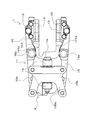
- FIG. 1 is a side view of a disc brake device according to an embodiment of the present invention.
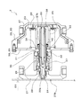
- FIG. 2 is a plan view of the disc brake device shown in FIG. 1. It is sectional drawing of the brake cylinder apparatus which concerns on 1st Embodiment of this invention. It is a figure which shows the state seen from the arrow C direction about the brake output part and the front-end
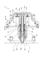
- FIG. 4 is a cross-sectional view of the brake cylinder device shown in FIG. 3 for illustrating a case where the brake cylinder device operates without automatic gap adjustment by a gap adjustment mechanism.
- FIG. 4 is a cross-sectional view of the brake cylinder device shown in FIG. 3 for illustrating a case where the brake cylinder device operates without automatic gap adjustment by a gap adjustment mechanism.
- FIG. 4 is a cross-sectional view of the brake cylinder device shown in FIG. 3 for illustrating a case where the brake cylinder device operates without automatic gap adjustment by a gap adjustment mechanism.
- FIG. 4 is a cross-sectional view of the brake cylinder device shown in FIG. 3 for illustrating a case where the brake cylinder device operates without automatic gap adjustment by a gap adjustment mechanism.
- FIG. 4 is a cross-sectional view of the brake cylinder device shown in FIG. 3 for illustrating a case where the brake cylinder device operates without automatic gap adjustment by a gap adjustment mechanism.
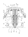
- FIG. 4 is a cross-sectional view of the brake cylinder device shown in FIG. 3 for illustrating an operation when automatic clearance adjustment is performed by a clearance adjustment mechanism.
- FIG. 4 is a cross-sectional view of the brake cylinder device shown in FIG. 3 for illustrating an operation when automatic clearance adjustment is performed by a clearance adjustment mechanism.
- FIG. 4 is a cross-sectional view of the brake cylinder device shown in FIG. 3 for illustrating an operation when automatic clearance adjustment is performed by a clearance adjustment mechanism.
- FIG. 4 is a cross-sectional view of the brake cylinder device shown in FIG. 3 for illustrating an operation when automatic clearance adjustment is performed by a clearance adjustment mechanism.
- FIG. 4 is a cross-sectional view of the brake cylinder device shown in FIG. 3 for illustrating an operation when automatic clearance adjustment is performed by a clearance adjustment mechanism.
- FIG. 4 is a cross-sectional view of the brake cylinder device shown in FIG.
- FIG. 4 is a cross-sectional view of the brake cylinder device shown in FIG. 3 for illustrating an operation when automatic clearance adjustment is performed by a clearance adjustment mechanism.
- FIG. 4 is a cross-sectional view of the brake cylinder device shown in FIG. 3 for illustrating an operation when automatic clearance adjustment is performed by a clearance adjustment mechanism.
- FIG. 4 is a cross-sectional view of the brake cylinder device shown in FIG. 3 for illustrating an operation when automatic clearance adjustment is performed by a clearance adjustment mechanism.
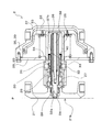
- FIG. 4 is a cross-sectional view of the brake cylinder device shown in FIG. 3 for illustrating an operation when a gap adjustment operation is performed in an idling state.
- FIG. 4 is a cross-sectional view of the brake cylinder device shown in FIG. 3 for illustrating an operation when a gap adjustment operation is performed in an idling state.
- FIG. 4 is a cross-sectional view of the brake cylinder device shown in FIG. 3 for illustrating an operation when a gap adjustment operation is performed in an
- FIG. 4 is a cross-sectional view of the brake cylinder device shown in FIG. 3 for illustrating an operation when a gap adjustment operation is performed in an idling state.
- FIG. 4 is a cross-sectional view of the brake cylinder device shown in FIG. 3 for illustrating an operation when a gap adjustment operation is performed in an idling state. It is sectional drawing of the brake cylinder apparatus which concerns on 2nd Embodiment of this invention.
- FIG. 1 is a side view of a disc brake device 1 according to an embodiment of the present invention as seen from the axle direction.
- FIG. 2 is a plan view of the disc brake device 1 shown in FIG. 1 as viewed from above.
- a disc brake device 1 shown in FIGS. 1 and 2 includes a brake cylinder device 2, a caliper body 11 equipped with the brake cylinder device 2 and attached to the vehicle main body 100 so as to be relatively displaceable in the axle direction.
- the pair of brake pads (13, 13) are attached to the caliper body 11 via the back plate 12.
- the disc brake device 1 is a disc on the axle side that rotates in conjunction with the rotation of the wheels (not shown) of the railway vehicle by the pair of brake pads (13, 13) when the brake cylinder device 2 is operated.
- the disc-shaped brake disc 101 is sandwiched to generate a braking force.
- the brake disc 101 is formed in a disc shape having front and back braking surfaces (101a, 101a) formed so as to be orthogonal to the rotation axis.
- the brake pads (13, 13) move the brake discs 101 on both sides from a direction substantially parallel to the rotation axis direction of the brake disc 101 with respect to the braking surfaces (101a, 101a). It is pressed so that it may be pinched.
- the caliper body 11 includes a coupling member 14 and a pair of brake levers (15, 15).
- the coupling member 14 is attached to a bracket 100a fixed to the bottom surface of the vehicle main body 100 via a swing pin 14a so as to be swingable about an axis parallel to the traveling direction of the vehicle.
- a pair of brake levers (15, 15) are installed so as to be swingable via the pair of fulcrum pins 15a in a substantially symmetrical manner with respect to the coupling member 14.
- the fulcrum pin 15 a is installed so as to extend in a direction perpendicular to the axial direction of the swing pin 14 a when viewed from the rotational axis direction of the disc brake 101.
- the pair of brake levers (15, 15) is configured such that a brake cylinder device 2 is attached to one end side thereof via a cylinder support pin 15b, and one end side is driven by the brake cylinder device 2.
- a pair of brake levers (15, 15) are a pair of back plates (12, 12) which hold
- the back plate 12 is swingably attached to the brake lever 15 via a support pin 12a extending in parallel with the fulcrum pin 15a.
- the cylinder body 20 of the brake cylinder device 2 is attached to one brake lever 15 and the brake output portion 21 is attached to the other brake lever 15.
- operation of is performed. Accordingly, the vicinity of the cylinder support pin 15b of the pair of brake levers (15, 15) is driven so as to be separated from each other or close to each other.
- the disc brake device 1 operates such that the pair of brake levers (15, 15) operate with the fulcrum pin 15a as a support shaft and the brake pad 13 is sandwiched between the brake pads 13. become.
- the pair of brake levers (15, 15) one brake pad 13 provided on one brake lever 15 comes into contact with the braking surface 101a of the brake disc 101 first.
- the other brake lever 15 presses the other brake pad 13 against the braking surface 101 a of the brake disc 101 by using a reaction force received from the one brake pad 13 in contact with the braking surface 101 a.
- the brake disc 101 is sandwiched between the pair of brake pads (13, 13), and the rotation of the brake disc 101 is caused by the frictional force generated between the brake pads (13, 13) and the braking surfaces (101a, 101a).
- the wheel is braked and the rotation of the wheels of the railway vehicle provided coaxially with the brake disk 101 is braked.
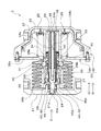
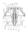
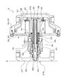
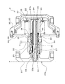
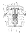
- FIG. 3 is a cross-sectional view of the brake cylinder device 2.
- the brake cylinder device 2 shown in FIG. 3 is configured in the same manner as the brake cylinder device 2 shown in FIGS. 1 and 2, but a part of the outer shape is changed and shown. Both ends of the brake cylinder device 2 in the brake operation direction are respectively connected to the cylinder support pins 15b.
- the brake cylinder device 2 includes a cylinder body 20, a brake output unit 21, a piston 22, a piston spring 23, a screw shaft 24, a guide tube 25, a pusher spring 26, a clutch nut 27, a front stopper 28, a first clutch 29,
- An adjustment stopper 30, an adjustment spring 31, a second clutch 32, an adjustment sleeve 33, a spring stopper 34, a pusher spring guide 38, a bearing 40, an engagement mechanism 42, and the like are provided.
- the parts other than the adjustment sleeve 33 are formed of, for example, a metal material such as an iron-based material, and the adjustment sleeve 33 is formed of, for example, a resin material.
- the adjustment stopper 30, the pusher spring guide 38, and the like are shown not in cross section but in outer shape.
- the cylinder body 20 is composed of a first casing part 35 and a second casing part 36, and the inside is formed to be hollow. Inside the cylinder body 20 are a piston 22, a piston spring 23, a part of a screw shaft 24, a guide tube 25, a pusher spring 26, a clutch nut 27, a front stopper 28, a first clutch 29, an adjustment stopper 30, and an adjustment spring 31.
- the second clutch 32, the pusher spring guide 38, the adjustment sleeve 33, the spring stopper 34, and the like are accommodated.
- the first casing portion 35 is formed in a substantially cup shape having a bottom portion, and the second casing portion 36 is fixed by bolts so as to close the open side of the first casing portion 35.
- the end portion of the first casing portion 35 is connected to one brake lever 15 by a cylinder support pin 15b.
- the second casing portion 36 is formed in a flat plate-like portion 36a formed in a flange shape so as to close the first casing portion 35, and in a cylindrical shape protruding perpendicularly to the flat plate-like portion 36a.
- a cylindrical portion 36b is provided.
- the piston 22 is arranged so as to partition the inside of the cylinder body 20, and is provided to be slidably contacted with the inner peripheral surface of the first casing portion 35 while being slidable in the axial direction with respect to the first casing portion 35. Yes.
- a pressure chamber 37 is formed in the cylinder body 20 by a space defined by the piston 22 and the first casing portion 35. The pressure chamber 37 is configured to supply and discharge compressed air as a pressure fluid through a communication path (not shown).
- the piston spring 23 is provided as a coiled spring disposed on the opposite side to the pressure chamber 37 via the piston 22 in the cylinder body 20.
- the piston 22 and the flat plate portion 36 a of the second casing portion 36 are provided. It is arranged between.
- the urging force of the piston spring 23 is transmitted to the piston 22 that defines the pressure chamber 37 in the cylinder body 20.
- the piston spring 23 is disposed in the cylinder body 20 so as to bias the piston 22 toward the pressure chamber 37 side.
- the piston 22 moves relative to the cylinder body 20 against the urging force of the piston spring 23, and the brake direction (the direction indicated by the arrow A in FIG. 3). Configured to move to.
- the piston 22 is moved in the counter-braking direction (direction indicated by arrow B in FIG. 3) opposite to the braking direction by the biasing force of the piston spring 23. It is configured.
- the brake output unit 21 is connected to the piston 22 via a screw shaft 24, a guide tube 25, and the like, which will be described later, and is provided so as to be movable together with the piston 22. Thereby, the brake output unit 21 is provided so as to be movable in a braking direction (arrow A direction) protruding from the cylinder body 20 and an anti-braking direction (arrow B direction) approaching the cylinder body 20. Moreover, the brake output part 21 is connected with the other brake lever 15 by the cylinder support pin 15b.
- a bellows structure disposed so as to cover the periphery of the cylindrical portion 36 b of the second casing portion 36 is provided as a protective cover between the brake output portion 21 and the cylinder body 20.
- the screw shaft 24 is provided as a shaft-like member that is connected to the brake output portion 21 and has a screw 24a formed on the outer periphery.
- the screw shaft 24 is formed to be hollow so as to open toward the side opposite to the brake output portion 21 (in this embodiment, the piston 22 side). That is, the hollow area inside the screw shaft 24 is provided as an axial hole 24 b extending along the axial direction, and is opened only on the side opposite to the brake output portion 21.
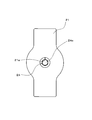
- FIG. 4 is a diagram showing a state in which the brake output portion 21 and the tip end portion of the screw shaft 24 are viewed from the direction of arrow C in FIG.
- the screw shaft 24 is provided with a hexagonal head portion 24c, which is an operation engagement portion that can be engaged with an operation tool (for example, a socket wrench), at the tip portion.
- the hexagonal head portion 24c is formed as a portion having a hexagonal columnar side surface (for example, formed in the same form as the head portion of the hexagonal bolt), and rotates integrally with the main body portion of the screw shaft 24. So that it is fixed.
- the through-hole is formed in the center part of the brake output part 21, and the front-end
- the hexagonal head portion 24 c at the tip end portion of the screw shaft 24 is disposed in an opening hole 21 a that forms a part of the through hole and that opens to the end face of the brake output portion 21.
- the engaging mechanism 42 is disposed on the outer periphery on the distal end side of the screw shaft 24 and is provided as a mechanism for engaging the screw shaft 24 and the brake output portion 21.
- the engagement mechanism 42 includes an outer peripheral engagement portion 43 and an engagement spring 44.
- the engagement block 45 is provided in the center part in which the through-hole was formed.
- the engagement block 45 is provided as a portion that engages with the engagement mechanism 42 in the brake output portion 21, and is fixed to the main body portion of the brake output portion 21 in the through hole.
- the engaging block 45 is formed with a hole penetrating therethrough so that the tip end side of the screw shaft 24 can slide.
- the outer peripheral engaging portion 43 of the engaging mechanism 42 is configured to have a cylindrical fixing portion and an engaging tooth portion that are integrally formed.
- the cylindrical fixing portion is formed in a cylindrical shape and is fixed to the outer periphery of the screw shaft 24.
- the engaging tooth portion is provided at one end of the cylindrical fixing portion, and is formed as a flange-shaped portion or as an umbrella-shaped portion having a large hole at the center, and the brake output portion 21 has an engaging tooth 43a that can be engaged with 21.
- the engagement tooth portion is disposed to face the engagement block 45 in the central through hole of the brake output portion 21.
- the engagement tooth 45a engaged with the engagement tooth 43a in an engagement tooth part is formed in the part facing the said engagement tooth part in the engagement block 45 of the brake output part 21. As shown in FIG.
- the engagement spring 44 of the engagement mechanism 42 is provided as a coiled spring, and is disposed in the through hole in the center of the brake output portion 21 and is disposed on the outer periphery of the cylindrical fixed portion of the outer periphery engagement portion 43. Yes.
- the engagement spring 44 is disposed such that one end thereof is in contact with the side of the engagement tooth portion opposite to the side where the engagement teeth 43a are formed. Further, the engagement spring 44 is fixed to the brake output portion 21 so that the other end portion closes a part of the opening opposite to the opening hole 21a side in the central through hole of the brake output portion 21. It arrange
- the engagement spring 44 engages the engagement teeth 43a of the outer peripheral engagement portion 43 integrally fixed to the main body portion of the screw shaft 24 with the engagement teeth 45a of the engagement block 45 in the brake output portion 21.
- the outer peripheral engagement portion 43 is configured to be biased toward the brake direction. In this way, the screw shaft 24 and the brake output unit 21 are configured to be engaged via the engagement mechanism 42.
- the guide tube 25 is formed as a cylindrical member, and has one end fixed to and attached to the piston 22 and is disposed so as to penetrate the cylindrical portion 36b in the second casing portion 36 of the cylinder body 20. Yes.
- a bottom plate 25a is attached to an end portion fixed to the piston 22, and an end portion facing the brake output portion 21 is provided to be opened.
- the screw shaft 24 is accommodated in the space area inside.
- a pair of slit holes (25b, 25b) that are formed in a slit shape are provided on the peripheral wall of the guide tube 25 at a midway position in the cylindrical axis direction.
- the pair of slit holes (25b, 25b) are provided so as to be arranged at positions along the diameter direction of the cylindrical guide tube 25, and an adjustment stopper 30 described later penetrates from the inside toward the outside. It is formed as an opening arranged so as to.
- the pusher spring 26 is provided as a coiled spring and is disposed in the axial hole 24 b in the screw shaft 24.
- the axial hole 24b is provided with a step portion whose diameter decreases stepwise toward the back side.
- the pusher spring 26 is provided as a compression spring, and is disposed so that one end thereof is in contact with the stepped portion in the axial hole 24 b and the other end is in contact with the bottom plate 25 a of the guide tube 25. Yes.
- the pusher spring 26 is arranged so as to be able to urge the screw shaft 24 from the inside toward the brake direction with respect to the guide tube 25.
- the pusher spring guide 38 is formed as an axial portion that is fixed to the bottom plate 25 a of the guide tube 25 and is movably provided together with the guide tube 25.
- the pusher spring guide 38 is disposed so as to protrude toward the axial hole 24 b of the screw shaft 24, and is inserted inside the pusher spring 26.
- the pusher spring guide 38 is configured to restrict deformation of the pusher spring 26 in the buckling direction.
- the pusher spring guide 38 is inserted in a state in which a tip end portion thereof is in sliding contact with a portion of the diameter-reduced hole in the axial hole 24 b of the screw shaft 24.
- the pusher spring guide 38 has a distal end portion slidable with respect to the inside of the screw shaft 24.
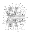
- FIG. 5 is an enlarged cross-sectional view showing a part of the brake cylinder device 2 shown in FIG.
- the clutch nut 27 is provided as a cylindrical member having an internal thread formed on the inner periphery, and is a screw shaft disposed on the brake output portion 21 side with respect to the cylinder body 20. 24 is configured to be screwed to the distal end side.
- the outer periphery of the clutch nut 27 at the midway position in the axial direction is formed so as to extend in the circumferential direction and to protrude outward in the radial direction, with respect to the front stopper 28 and the first clutch 29 described later. And a convex portion 27a that can be brought into contact with each other.
- the pusher spring 26 biases the clutch nut 27 screwed to the screw shaft 24 toward the front stopper 28 by biasing the screw shaft 24 from the inside. Is configured to do.
- the front stopper 28 is provided as a cylindrical member having a male screw portion on the outer periphery and a short axial length, and is formed as an integral member.
- the front stopper 28 is threadedly engaged with a female screw portion formed on the inner periphery of the tip portion of the guide tube 25 facing the brake output portion 21 in the male screw portion. That is, the front stopper 28 is fixed to the inner periphery of the guide tube 25 by screw connection.
- a groove extending in the circumferential direction is formed on the inner periphery of the distal end portion of the guide tube 25 on the brake output portion 21 side with respect to the front stopper 28.
- a snap ring 41 that engages with an end of the front stopper 28 on the brake output portion 21 side is fitted into the groove, thereby preventing the front stopper 28 from coming off.
- the front stopper 28 is disposed concentrically on the outer side with respect to the end of the clutch nut 27 on the brake output portion 21 side and the screw shaft 24 (so that the radial center positions coincide).
- the front stopper 28 is disposed so as to be able to contact the convex portion 27a from the front side which is the brake output portion 21 side with respect to the clutch nut 27 so as to restrict the movement of the clutch nut 27 with respect to the guide tube 25.
- the front stopper 28 is configured to be able to bias the clutch nut 27 and the screw shaft 24 to which the clutch nut 27 is screwed in the anti-braking direction as the guide tube 25 moves in the anti-braking direction.
- the first clutch 29 is provided as a cylindrical member having a short axial length, and is formed as an integral member that is a separate member from the front stopper 28.
- the first clutch 29 is press-fitted inside and fixed to the guide tube 25. Note that the end portion of the first clutch 29 is positioned in contact with a portion formed in a step shape on the inner periphery of the guide tube 25.
- the first clutch 29 is arranged concentrically outside the end of the clutch nut 27 on the piston 22 side and the screw shaft 24 (so that the radial center positions coincide).
- the first clutch 29 can come into contact with the convex portion 27a of the clutch nut 27 through a predetermined distance from the front stopper 28 from the rear side opposite to the brake output portion 21 side with respect to the clutch nut 27. Has been placed.
- the surface of the first clutch 29 that faces the clutch nut 27 is a tapered surface that is formed obliquely with respect to the axial direction so as to form a part of a conical curved surface with the axial direction of the screw shaft 24 as the center line. It is provided as. Further, the surface of the convex portion 27a of the clutch nut 27 facing the first clutch 29 is also formed obliquely with respect to the axial direction so as to form a part of a conical curved surface with the axial direction of the screw shaft 24 as the center line. Provided as a tapered surface. The surfaces of the first clutch 29 and the clutch nut 27 facing each other are formed as surfaces that are inclined at substantially the same angle with respect to the axial direction of the screw shaft 24 and are provided as surfaces that abut each other. .
- the adjustment stoppers 30 are provided as a pair, and are respectively fixed to a second clutch 32 described later formed as a ring-shaped member or a cylindrical member having a short axial length. Each adjustment stopper 30 is provided as a block-like member that protrudes outward in the radial direction of the second clutch 32.
- the pair of adjustment stoppers (30, 30) are fixed to the second clutch 32 described later so as to be disposed at positions along the diameter direction of the guide tube 25 and the screw shaft 24.
- the pair of adjustment stoppers (30, 30) are arranged so as to protrude through the pair of slit portions (25b, 25b) in the guide tube 25.
- the cylindrical portion 36b of the second casing portion 36 of the cylinder body 20 has a pair of stopper stroke restricting portions (39, 39) provided as holes formed in a slit shape extending in parallel with the axial direction of the screw shaft 24. 39) is provided at a position along the diameter direction of the cylindrical portion 36b.
- the protruding end portions of the respective adjustment stoppers 30 are arranged so as to be movable along the stopper stroke restricting portions 39, and the end portions in the brake direction and the end portions in the anti-brake direction of the stopper stroke restricting portions 39, respectively. It is arrange
- the adjustment stopper 30 is disposed so as to be relatively movable along the axial direction of the screw shaft 24 with respect to the clutch nut 27 and the guide tube 25, and has a movable range with respect to the cylinder body 20. It is configured to be regulated.
- the second clutch 32 to which the adjustment stopper 30 is fixed is formed as a ring-shaped member or a cylindrical member having a short axial length as described above, and around the screw shaft 24 and the adjustment sleeve 33 described later around the guide tube. 25 is arranged inside.
- the second clutch 32 is disposed so as to be capable of coming into contact with the clutch nut 27 from the rear side at the end in the braking direction, and is in contact with an adjustment spring 31 described later at the end in the anti-braking direction.
- teeth 32a are formed on the surface of the end portion of the second clutch 32 in the braking direction and facing the clutch nut 27 in the circumferential direction.
- teeth 27b are formed on the surface of the end of the clutch nut 27 in the anti-braking direction and facing the second clutch 32 in the circumferential direction.
- the teeth 32 a on the second clutch 32 side and the teeth 27 a on the clutch nut 27 side are formed as teeth that can engage the second clutch 32 and the clutch nut 27.
- the adjustment sleeve 33 is formed as a cylindrical member having flexibility by being formed of resin, and is arranged around the screw shaft 24.
- the adjustment sleeve 33 is provided with an engaging portion 33a formed as an uneven portion on the outer periphery on the end side in the brake direction.
- the clutch nut 27 is provided with an engaged portion 27c formed as an uneven portion that fits with the uneven portion of the engaging portion 33a on the inner circumference on the end side in the anti-braking direction.
- the adjustment sleeve 33 and the clutch nut 27 are integrally formed by engaging the engagement portion 33a on the adjustment sleeve 33 side and the engaged portion 27c on the clutch nut 27 side.
- the engaging portion 33a of the adjusting sleeve 33 is provided so as to engage with an engaged portion 27c formed on the inner peripheral side of the clutch nut 27 from the inside.
- the dimension in the radial direction of the adjustment sleeve 33 of the gap formed between the inner periphery of the adjustment sleeve 33 and the top of the screw thread of the screw 24a in the screw shaft 24 is determined by the engagement portion 33a and the engaged portion 27c.
- the adjustment spring 31 is provided as a coiled spring disposed around the adjustment sleeve 33.
- the adjustment spring 31 has one end abutted on (or connected to) the end of the second clutch 32 in the anti-brake direction, and the other end attached to the end of the adjustment sleeve 33 in the anti-brake direction. It arrange
- the spring stopper 34 and the bearing 40 constitute the spring receiver.
- the adjustment sleeve 33 is configured so that one end side is urged in the anti-braking direction by the other end side of the adjustment spring 31 abutting against the second clutch 32.
- the adjustment spring 31 is configured to be able to bias the clutch nut 27 that is engaged and integrated with the adjustment sleeve 33 in the anti-braking direction.
- the bearing 40 included in the above-described spring receiver is disposed between the outer periphery of the adjustment sleeve 33 and the inner periphery of the guide tube 35, and extends in the circumferential direction on the outer periphery of the end portion of the adjustment sleeve 33 in the anti-braking direction.
- the adjusting sleeve 33 is attached by engaging with the formed flange-shaped protrusion.
- the bearing 40 in the spring receiver has almost zero dimension in the radial direction of the guide tube 25 in the gap formed between the outer periphery of the bearing 40 (that is, the outer periphery of the spring receiver) and the inner periphery of the guide tube 25. It is arranged to be.
- the spring receiver including the bearing 40 may be disposed so that the outer periphery of the bearing 40 (the outer periphery of the spring receiver) and the inner periphery of the guide tube 25 are in sliding contact.
- the spring stopper 34 is provided as a cylindrical member disposed around the end of the adjustment sleeve 33 in the anti-braking direction.
- the spring stopper 34 has a flange-shaped portion at the end in the anti-brake direction, and abuts against the bearing 40 at the end surface in the anti-brake direction at the flange-shaped portion. Further, the end face in the brake direction in the flange-shaped portion is in contact with the other end side (end side in the anti-brake direction) of the adjustment spring 31. Since the bearing 40 is disposed between the spring stopper 34 and the adjustment sleeve 33, the adjustment sleeve 33 is configured to be rotatable with respect to the spring stopper 34.
- the end of the cylindrical portion of the spring stopper 34 in the braking direction is opposed to the end of the second clutch 32 in the anti-braking direction via a gap.
- the end portion in the brake direction of the cylindrical portion of the spring stopper 34 is disposed so as to contact the end portion in the anti-brake direction of the second clutch 32 when the adjustment spring 31 is greatly compressed and contracted. .
- the spring stopper 34 restricts the amount of displacement of the adjustment spring 31 whose one end side contacts the adjustment stopper 30 relative to the one end side and the adjustment spring 31 is elastically deformed to a predetermined amount or less. It is configured.
- the component of the spring receiver includes the bearing 40, so that the grease is simply applied to the disk-shaped member without using the bearing.
- the frictional force generated by this urging force does not hinder the rotation of the clutch nut 27 integrated with the adjustment sleeve 33. That is, since the bearing 40 is provided, the biasing force described above hardly affects the rotation direction of the preparation sleeve 33 and the clutch nut 27 that rotate together with the bearing 40. Adjustments can be made.
- the bearing 40 may be a rolling bearing or a sliding bearing as long as the sliding resistance between the adjusting spring 31 and the adjusting sleeve 33 can be lowered, and either a radial bearing or a thrust bearing. It does not matter.
- FIGS. 6 to 21 are sectional views of the brake cylinder device 2.
- the bellows structure disposed between the brake output portion 21 and the cylinder body 20 is not shown.
- the position of the cylinder body 20 is shown as a reference, and the components other than the cylinder body 20 are shown relative to the cylinder body 20.
- the position of the end portion 21b in the brake direction of the brake output portion 21 at which the brake output portion 21 can move relative to the cylinder body 20 to perform the braking operation is indicated by a two-dot chain line P (
- brake operation position P a position indicated by a two-dot chain line P is referred to as “brake operation position P”. That is, when the position of the end portion 21b of the brake output portion 21 with respect to the cylinder body 20 reaches the brake operation position P (a position where the braking force can be generated), the pair of brake pads (13, 13) in the disc brake device 1 are used. Comes into contact with the brake disc 101.
- FIG. 6 to 9 are cross-sectional views of the brake cylinder device 2 for explaining the case where the brake cylinder device 2 operates without automatic gap adjustment by the gap adjustment mechanism.
- the cross-sectional view of FIG. 6 shows a state before the brake operation is performed, that is, a state where the brake is released.
- a distance D1 between the end 21b of the brake output unit 21 and the brake operation position P in this state is indicated by an arrow in the drawing.
- the compressed air is supplied to the pressure chamber 37, so that the state shown in the sectional view of FIG. 6 is first shifted to the state shown in the sectional view of FIG. That is, as the compressed air is supplied to the pressure chamber 37, the piston 22 moves in the brake direction together with the guide tube 25 against the urging force of the piston spring 23. Then, the screw shaft 24 moves together with the guide tube 25 and the pusher spring 26 in the braking direction, and the end portion 21b of the brake output portion 21 reaches the brake operation position P.
- the state shown in FIG. 7 is a state at the moment when the end portion 21b of the brake output portion 21 reaches the brake operation position P and the pair of brake pads (13, 13) contact the brake disc 101. Power is not generated.
- the brake cylinder device 2 instantaneously shifts to the state shown in FIG. Will do. That is, the clutch nut 27 that has been separated from both the front stopper 28 and the first clutch 29 by being separated from the first clutch 29 comes into contact with the front stopper 28.
- FIG. 10 shows a state before the brake operation is performed, that is, a state where the brake is released.
- a distance D2 between the end 21b of the brake output unit 21 and the brake operation position P in this state is indicated by an arrow in the drawing.
- a distance D2 that is a gap from the end portion 21b of the brake output portion 21 to the brake operation position P when the brake is released is large. That is, the distance D2 is larger than the distance D1 (D2> D1).
- the gap is automatically adjusted by the gap adjustment mechanism.
- the compressed air is supplied to the pressure chamber 37, so that the state shown in the cross-sectional view of FIG. 10 is first shifted to the state shown in the cross-sectional view of FIG. That is, as the compressed air is supplied to the pressure chamber 37, the piston 22 moves in the brake direction together with the guide tube 25 against the urging force of the piston spring 23. Further, the screw shaft 24 moves in the braking direction together with the guide tube 25 and the pusher spring 26, and the spring receiver (spring stopper 34, bearing 40) and adjustment together with the adjustment sleeve 33 engaged with the clutch nut 27 screwed onto the screw shaft 24. The spring 31, the second clutch 32, and the adjustment stopper 30 also move in the braking direction.
- the adjustment stopper 30 fixed to the second clutch 32 comes into contact with the end of the stopper stroke restricting portion 39 in the brake direction. As a result, the adjustment stopper 30 reaches the forward limit, and the forward movement (braking direction) with respect to the cylinder body 20 is restricted.
- the second clutch 32 to which the adjustment stopper 30 is fixed and the adjustment sleeve 33 are disposed on the end side in the anti-braking direction.
- the adjustment spring 31 is compressed between the spring stopper 34.
- the adjustment spring 31 is compressed by the same dimension (dimension F1) as the distance F1, and the stored force of the adjustment spring 31 is stored.
- the state shown in FIG. 12 is a state at the moment when the end portion 21b of the brake output unit 21 reaches the brake operation position P and the pair of brake pads (13, 13) contact the brake disc 101. It has not occurred. In this state, the movement in the brake direction of the screw shaft 24 and the clutch nut 27 screwed to the screw shaft 24 is restricted. Then, by continuing the supply of compressed air to the pressure chamber 37 from the state shown in FIG. 12, the guide tube 25 moves in the brake direction together with the piston 22 as shown in the sectional view of FIG. 25, the front stopper 28 and the first clutch 29 move forward (in the braking direction).
- the front stopper 28 that has been in contact with the clutch nut 27 is separated from the clutch nut 27, and the first clutch 29 that has been separated from the clutch nut 27 is in contact with the clutch nut 27.
- the pair of brake pads (13, 13) press the brake disc 101, and the braking force is output.
- the accumulated force of the adjustment spring 31 corresponding to the compression dimension of the dimension F1 shown in FIG. 13 is maintained as it is.
- the screw nut 24 and the brake output portion 21 do not move in the anti-braking direction, and the clutch nut 27 is moved in the anti-braking direction by the accumulated force corresponding to the dimension F1 of the adjustment spring 31. This will cause a state to be energized.
- the clutch nut 27 is released from contact with the first clutch 29 and is not in contact with the front stopper 28, and the clutch nut 27 is also applied to the second clutch 32. Since they are not in contact with each other, the clutch nut 27 can rotate with respect to the screw shaft 24.
- the dimension of the adjustment spring 31 is increased.
- the clutch nut 27 is rotated with respect to the screw shaft 24 so as to move in the anti-braking direction by the accumulated force corresponding to F1.
- the dimension F1 shown in FIG. 14 decreases.
- the state in which the clutch nut 27 rotates with respect to the screw shaft 24 without contacting any of the front stopper 28, the first clutch 29, and the second clutch 32 is as shown in FIG.
- the clutch nut 27 becomes non-rotatable. Note that the rotation of the clutch nut 27 performed until the dimension F1 becomes zero is not limited to being completed while the brake operation and the brake release operation are performed once, while the brake operation and the brake release operation are performed a plurality of times. May be completed.
- the distance between the end portion 21b of the brake output unit 21 and the brake operation position P is a distance.
- the distance changes to a distance D3 (D3 ⁇ D2) which is a distance smaller than D2. That is, since the clutch nut 27 moves relative to the screw shaft 24 in the anti-brake direction during the brake releasing operation, the position of the screw shaft 24 moves in the brake direction from the state before the brake releasing operation. The release operation ends. Then, the screw shaft 24 and the brake output portion 21 are shifted to a position where the screw shaft 24 and the brake output portion 21 protrude from the cylinder body 20 as compared with the state before the brake operation and the brake release operation. Thereby, the gap to the brake operation position P in the state where the brake is released is automatically adjusted.
- the operation of the brake cylinder device 2 when the clearance adjustment operation is forcibly performed Will be described with reference to FIGS.
- the cross-sectional view of FIG. 18 shows a state before compressed air is supplied to the compression chamber 37 in the above-described idling state (that is, a state corresponding to the aforementioned brake release state). For example, a state in which the clearance adjustment operation is about to be performed after the brake pad 13 is replaced in the disc brake device 1 is shown.
- the adjustment stopper 30 fixed to the second clutch 32 comes into contact with the end of the stroke restricting portion 39 in the brake direction. As a result, the adjustment stopper 30 reaches the forward limit, and the forward movement (braking direction) with respect to the cylinder body 20 is restricted.
- the force capable of urging the clutch nut 27 in the anti-braking direction is accumulated as the accumulated force of the adjustment spring 31 via the spring stopper 34, the bearing 40 and the adjustment sleeve 33.
- the clutch nut 27 integrally formed with the adjustment sleeve 33 with respect to the second clutch 32 to which the adjustment stopper 30 whose movement range is restricted by the cylinder body 20 is fixed is indicated by an arrow in FIG. , Relative movement by distance F2.
- the adjustment spring 31 is compressed by the same dimension (dimension F2) as the distance F2, and the stored force of the adjustment spring 31 is stored.
- the clutch nut 27 is separated from the front stopper 28 and is also not in contact with the first clutch 29 while being separated. For this reason, the clutch nut 27 is not in contact with any of the front stopper 28, the first clutch 29, and the second clutch 32, and can rotate with respect to the screw shaft 24. At this time, since the screw shaft 24 is urged by the pusher spring 26, the clutch nut 27 is rotated with respect to the screw shaft 24 by the urging force of the pusher spring 26.
- the screw shaft 24 moves relative to the clutch nut 27 in the brake direction and protrudes.
- the brake pad 13 comes into contact with the brake disc 101, the movement of the screw shaft 24 by the urging force of the pusher spring 26 is stopped, and the rotation of the clutch nut 27 with respect to the screw shaft 24 is stopped.
- the clutch nut 27 due to the urging force of the pusher spring 26 is obtained. The rotation with respect to the screw shaft 24 stops.
- the clutch nut 27 is not applied to any of the front stopper 28, the first clutch 29, and the second clutch 32. It is in a state in which it can rotate with respect to the screw shaft 24 without contact. For this reason, the clutch nut 27 is rotated with respect to the screw shaft 24 so as to be biased by the stored force stored in the adjustment spring 31 and move in the anti-braking direction. As the clutch nut 27 rotates with respect to the screw shaft 24 in this way, the clutch nut 27 comes into contact with the first clutch 29. In this state, the state of the gap adjustment mechanism is the same as the state shown in the cross-sectional view of FIG.
- the state is continued until there is no gap between the clutch nut 27 and the second clutch 32 and the clutch nut 27 and the second clutch 32 come into contact with each other.
- the rotation of the clutch nut 27 that is performed until the clutch nut 27 and the second clutch 32 come into contact with each other is not limited to the case where the operation corresponding to the brake operation and the brake release operation is completed once. And the operation corresponding to the brake releasing operation may be completed during a plurality of times.
- the clearance adjustment mechanism includes the clutch nut 27, the first clutch 29, the second clutch 32, the screw shaft 24, the guide tube 25, the pusher spring 26, the front stopper 28, and the adjustment stopper. 30 and an adjustment spring 31 and the like.
- the gap adjustment is not performed by elastic deformation of rubber or the like, and a configuration that is not easily affected by the surrounding environment such as temperature and humidity can be realized.
- it since it is not necessary to provide a bearing in the structure which attaches the guide tube 25 with respect to piston 22, it can attain size reduction of the diameter dimension of the rear side (end part side of an anti-brake direction) in the cylinder main body 20.
- the brake cylinder device 2 having the gap adjustment mechanism for automatically adjusting the gap to the brake operation position P in the state where the brake is released, the influence of the surrounding environment such as temperature and humidity is affected. Therefore, it is possible to reduce the size of the cylinder main body 20 in the radial direction.
- the second clutch 32 and the clutch nut are engaged regardless of whether the brake operation is being performed or the brake is being released. 27 is maintained, and the second clutch 32 and the clutch nut 27 are prevented from coming off. That is, in a state where the clearance adjustment operation is not performed, the clutch nut 27 is biased in the anti-braking direction by the adjustment spring 31 whose one end is in contact with the second clutch 32, so that the second clutch 32 and the clutch nut 27 is kept in contact.
- the clutch nut 27 is prevented from rotating with respect to the screw shaft 24 at a timing other than the clearance adjustment operation, and the position of the clutch nut 27 with respect to the screw shaft 24 is prevented from being displaced due to vibration or the like. Is done.
- the brake output portion 21 protrudes excessively in the brake direction with respect to the cylinder body 20 or the brake output portion 21 with respect to the cylinder body 20.
- the amount of protrusion in the brake direction will be insufficient.
- the brake pad 13 is constantly in contact with the brake disc 101 and rubbed. In this case, there is a possibility that the wear of the brake pad 13 is promoted and the replacement cycle of the brake pad 13 is accelerated.
- the clutch nut 27 is prevented from rotating with respect to the screw shaft 24 at timings other than the clearance adjustment operation, and the screw of the clutch nut 27 is caused by vibration or the like.
- the position with respect to the shaft 24 is prevented from shifting. For this reason, the wear of the brake pad 13 is promoted and the replacement cycle of the brake pad 13 is accelerated, or the timing of generating the braking force during the braking operation is delayed even when the gap adjustment is not originally required. Can be prevented.
- the pusher spring 26 that biases the screw shaft 24 is disposed inside the screw shaft 24 formed in the hollow structure, and the clutch nut 27 that is screwed to the screw shaft 24 is connected to the front stopper 28. Configured to urge toward. For this reason, the pusher spring 26 can be disposed by efficiently utilizing the space in the brake cylinder device 2. Thereby, in the brake cylinder apparatus 2, space efficiency can be improved and size reduction can be further achieved.
- the pusher spring guide 38 that extends inside the coiled pusher spring 26 and restricts the deformation of the pusher spring 26 in the buckling direction is provided. For this reason, even when the size of the gap to be adjusted as the gap adjusting mechanism is increased and the long pusher spring 26 is required, the buckling of the pusher spring 26 can be efficiently prevented.
- the pusher spring guide 38 that is provided so as to be movable together with the guide tube 25 is slidably disposed on the inner side of the screw shaft 24. For this reason, the structure which maintains the positional relationship of the screw shaft 24 and the piston 22 on the same axis
- the front stopper 28 and the first clutch 29 are provided as separate separate members and are individually fixed to the guide tube 25. For this reason, it is not necessary to couple
- the clutch nut 27 in which the front stopper 28 and the first clutch 29 are arranged at the front and rear is not required to be separated by a separate coupling means as a split structure. Thereby, the structure regarding the front stopper 28, the 1st clutch 29, and the clutch nut 27 can be simplified, As a result, the brake cylinder device 2 whole can be reduced in size and weight.
- the brake cylinder device 2 can be further miniaturized.
- the front stopper 28 formed as an integral member is fixed to the inner periphery of the guide tube 25 by screw connection. Therefore, the front stopper 28 can be easily replaced at the time of maintenance, and the maintainability can be improved.
- the adjustment spring 31 is disposed between the cylindrical adjustment sleeve 33 disposed around the screw shaft 24 and the second clutch 32 to which the adjustment stopper 30 is fixed. With the relative movement of the adjustment sleeve 33 with respect to the 30 and the second clutch 32, a force for moving the clutch nut 27 in the anti-braking direction with respect to the screw shaft 24 during the clearance adjustment operation is accumulated.
- the adjustment sleeve 33 is provided as a flexible member, and the engagement portion 33a on the adjustment sleeve 33 side and the engaged portion 27c on the clutch nut 27 side are engaged, whereby the adjustment sleeve 33 and the clutch nut are engaged. 27 is integrated.
- the engagement portion 33a can be engaged with the engaged portion 27c, and the adjustment sleeve 33 and the clutch can be engaged without using a separate fastening member.
- the nut 27 can be integrated. As described above, in the structure in which the adjustment sleeve 33 and the clutch nut 27 are integrated, a separate fastening member is not required, and thus the brake cylinder device 2 can be further reduced in size.
- the adjustment sleeve 33 is configured to be engaged from the inside of the clutch nut 27, and a gap between the inner periphery of the adjustment sleeve 33 and the top of the screw thread of the screw 24 a of the screw shaft 24.
- the dimension is set to be smaller than the radial dimension of the concavo-convex portion that fits in the engaging portion 33a and the engaged portion 27c (overlap margin of the concavo-convex portion in the radial direction of the adjustment sleeve 33).
- the engaging portion 33a of the adjusting sleeve 33 having flexibility is disposed between the clutch nut 27 and the screw shaft 24 formed of a metal material.
- the dimensional relationship is set to prevent the 33a from being deformed to the screw shaft 24 side and disengaged from the engaged portion 27c.
- the other end side of the adjustment spring 31 urges the adjustment sleeve 33 via the bearing 40. Therefore, when the adjustment sleeve 33 is urged by the accumulated force of the adjustment spring 31, the adjustment spring 33 is adjusted.
- the clutch nut 27 smoothly rotates together with the sleeve 33 and moves in the braking direction. Since the bearing 40 in the spring receiver is disposed so that the gap with the guide tube 25 is substantially zero or in sliding contact with the guide tube 25, the screw shaft 24 with respect to the guide tube 25 through the bearing 40 of the spring receiver. Can be supported, and the screw shaft 24 can be prevented from being inclined with respect to the guide tube 25.
- the spring stopper 34 is provided for restricting the amount of displacement when the adjustment spring 31 is elastically deformed to a predetermined amount or less so that the accumulated force for the clearance adjustment operation is performed. For this reason, even when the gap adjustment operation is forcibly performed in the operation in the swinging state where the braking force is not generated in the operation in which the gap adjustment operation is performed as in the related art, the adjustment spring is used by the spring stopper 34. 31 strokes are regulated. For this reason, the adjustment spring 31 is not excessively compressed or expanded, and the gap adjustment operation can be forcibly performed even in the idling state.
- the gap adjustment operation can be forcibly performed even in the idling state, and thus corresponds to the brake operation and the brake release operation all at once in the vehicle or the entire knitting.
- the gaps in the entire brake cylinder device 2 are automatically adjusted.
- the gap can be automatically adjusted, and the work and labor required for replacing the brake pad 13 can be greatly reduced, and considerable efficiency can be achieved.
- the clutch nut 27 and the second clutch 32 are Are engaged through the teeth (27b, 32a) formed on the opposing surfaces, so that the clutch nut 27 can be reliably prevented from rotating with respect to the screw shaft 24 due to vibration or the like.
- the clutch nut 27 and the second clutch 32 are engaged via the teeth (27b, 32a), even if the clutch nut 27 is engaged only at the tip portion of the teeth (27b, 32a), the clutch nut It is possible to reliably prevent 27 from rotating with respect to the screw shaft 24.
- the hexagonal head portion 24 c that is an engaging portion for operation is provided on the tip portion that is disposed so as to face the outside through the brake output portion 21, and
- the screw shaft 24 and the brake output portion 21 are engaged by the engagement mechanism 42 disposed on the outer periphery.
- the engaging mechanism 42 includes an outer peripheral engaging portion 43 having an engaging tooth 43a and an engaging spring 44.
- the engaging spring 44 biases the outer peripheral engaging portion 43 in the brake direction, thereby engaging the engaging mechanism 43.
- the screw shaft 24 and the brake output unit 21 are configured to engage with each other through the tooth 43a.
- the engagement between the outer peripheral engagement portion 43 and the brake output portion 21 via the engagement teeth 43 a is released against the spring force of the engagement spring 44, and the engagement between the screw shaft 24 and the brake output portion 21.
- the screw shaft 24 can be manually rotated by releasing the connection and further rotating the screw shaft 24 with an operation tool. Thereby, the positional relationship between the screw shaft 24 and the clutch nut 27 can be easily returned to the initial state which is the state before the gap adjustment is performed.
- the disc brake device 1 including the brake cylinder device 2 provided with the gap adjusting mechanism for automatically adjusting the gap to the brake operation position P in the state where the brake is released,
- the gap adjusting mechanism for automatically adjusting the gap to the brake operation position P in the state where the brake is released
- FIG. 22 is a cross-sectional view of the brake cylinder device 3 according to the second embodiment.
- the brake cylinder device 3 shown in FIG. 22 is provided as a brake cylinder device equipped to the disc brake device 1 in the same manner as the brake cylinder device 2 of the first embodiment. Note that, in FIG. 22, some components in the brake cylinder device 3 are illustrated not in cross section but in outer diameter.
- the brake cylinder device 3 is similar to the brake cylinder device 2 of the first embodiment.
- the parts other than the adjustment sleeve 33 are formed of, for example, a metal material such as an iron-based material, and the adjustment sleeve 33 is formed of, for example, a resin material.
- the brake cylinder device 3 is configured similarly to the brake cylinder device 2 of the first embodiment.
- the brake cylinder device 3 is further provided with a force-increasing mechanism 51 and is configured so that the moving direction of the piston 50 moves in the direction opposite to the moving direction of the piston 22 of the first embodiment. This is different from the brake cylinder device 2 of the embodiment.
- a configuration different from that of the first embodiment will be described, and elements configured to have the same functions as those of the first embodiment are denoted by the same reference numerals in the drawings. Therefore, the description is omitted.
- the piston 50 includes a disk-shaped portion 52 and a pair of plate-shaped portions 53 (projecting from the disk-shaped portion 52 in parallel to the screw shaft 24 and the guide tube 25 in the anti-braking direction (direction indicated by arrow B in FIG. 22). In FIG. 22, only one plate-like portion 53 is shown.
- the second casing portion 36 of the cylinder 20 is formed with a cylindrical portion 54 that extends on the inner side toward the first casing portion 35 (that is, in the anti-braking direction).
- a through hole 52a is formed in the center of the disc-shaped portion 52, and the cylindrical portion 54 of the cylinder body 20 passes through the through hole 52a. Thereby, the piston 50 is disposed between the outer peripheral surface of the cylindrical portion 54 and the inner peripheral surface of the second casing 36.
- the piston 50 is disposed so as to divide the space between the outer peripheral surface of the cylindrical portion 54 and the inner peripheral surface of the second casing portion 36 into two, and is relative to the cylinder body 20 along the axial direction. It is configured to be movable.
- a pressure chamber 37 is defined between the piston 50 and the second casing portion 36.
- the cylinder body 20 is provided with a pair of guide shafts 55 (only one guide shaft 55 is shown in FIG. 22) extending in parallel with the axial direction of the screw shaft 24 and the guide tube 25.
- the disc-shaped portion 52 of the piston 50 is provided with a guide hole 52b through which each guide shaft 55 passes.
- a piston spring 23 that urges the piston 50 toward the brake output portion 21 (that is, toward the brake direction that is a direction indicated by an arrow A in FIG. 22) is disposed. ing.
- Each plate-like portion 53 of the piston 50 is provided with an inclined surface 53a that spirally inclines with respect to the direction of the central axis of the screw shaft 24 and the guide tube 25 and the circumferential direction around the central axis. ing.
- each roller 61 attached rotatably with respect to the rotation member 56 mentioned later is arrange
- the force-increasing mechanism 51 moves the guide tube 25, the pusher spring 26, the screw shaft 24, and the like in the braking direction (the direction indicated by the arrow A in FIG. 22) opposite to the moving direction of the piston 50.
- the mechanism is provided to act on the guide tube 25. That is, when compressed air is supplied to the pressure chamber 37 and the piston 50 moves in the anti-braking direction within the cylinder body 20, the force increased by the force increasing mechanism 51 acts on the guide tube 25 attached to the force increasing mechanism 51. Then, the guide tube 25, the pusher spring 26, the screw shaft 24, etc. move in the braking direction. For this reason, the brake output unit 21 connected to the screw shaft 24 moves in the brake direction via the force-increasing mechanism 51 that increases the force generated in the piston 50 as the piston 50 moves in the anti-brake direction. .
- the force-increasing mechanism 51 includes the aforementioned inclined surface 53a provided on the piston 50, the rotating member 56, the first receiving member 57, the second receiving member 58, the first rolling member 59, the second rolling member 60, and the like. It is prepared for.
- the rotation member 56 is provided as a disk-shaped member that rotates in a predetermined rotation direction around the central axis of the screw shaft 24 and the guide tube 25, and a through hole is formed at the center.
- the rotating member 56 is urged by the inclined surface 53a of the piston 50 when the piston 50 moves in the anti-braking direction, and the predetermined rotation about the central axis of the screw shaft 24 and the guide tube 25 is performed. It is configured to rotate in the direction.
- the screw shaft 24 and the guide tube 25 are provided so as not to rotate about the central axis with respect to the cylinder body 20, and the rotation of the rotation member 56 in the predetermined rotation direction is performed. And is configured to move in the braking direction.
- the rotating member 56 is provided with a pair of shaft portions that protrude outward in the radial direction from the outer peripheral surface of the disk-shaped portion, and the inclined surface 53a of the piston 50 with respect to each shaft portion.
- a roller 61 that contacts the outer peripheral surface of the roller 61 is rotatably attached.
- the first receiving member 57 is provided as a disk-like member having a through-hole formed in the center, and is arranged around the central axis of the screw shaft 24 and the guide tube 25 and fixed to the outer periphery of the guide tube 25. Has been.
- the first receiving member 57 is disposed so as to face the rotating member 56 on the brake direction side in the direction parallel to the central axis direction of the screw shaft 24 and the guide tube 25.
- a first inclined groove (not shown) is formed on the surface of the rotating member 56 facing the first receiving member 57 so that the depth of the rotating member 56 changes with an inclination with respect to the rotating direction of the rotating member 56. (Omitted) is provided.
- a first rolling member 59 (illustrated by a broken line in FIG. 22) that can roll along the inner surface of the first inclined groove is disposed in the first inclined groove.
- the first rolling member 59 is provided as a spherical member and is supported while being sandwiched between the first receiving member 57 and the rotating member 56.
- a plurality of the first inclined grooves and the first rolling members 59 are provided so as to be positioned along the circumference of one circle centered on the central axis of the screw shaft 24 and the guide tube 25.
- a spring 62 is disposed between the step formed on the inner peripheral side of the end portion in the braking direction of the first receiving member 57 and the step formed on the inner wall of the cylindrical portion 54 of the second casing portion 36. Has been. The spring 62 urges the first receiving member 57 in the anti-braking direction. Further, in the cylinder main body 20 of the brake cylinder device 3, a portion of the cylindrical portion 54 that constitutes a step portion that comes into contact with the spring 62 also serves as a function of the stopper stroke restricting portion 39.
- the second receiving member 58 is provided as a disk-shaped member having a through-hole formed at the center, and is disposed around the central axes of the screw shaft 24 and the guide tube 25, and the first casing portion 35 of the cylinder body 20. It is fixed against.
- the second receiving member 58 is opposed to the rotating member 56 on the side opposite to the brake direction in the direction parallel to the central axis direction of the screw shaft 24 and the guide tube 25, that is, the first receiving member in the rotating member 56. It arrange
- a second inclined groove (not shown) is formed on the surface of the rotating member 56 facing the second receiving member 58 so that the depth changes with the rotation direction of the rotating member 56. (Omitted) is provided.
- a second rolling member 60 (illustrated by a broken line in FIG. 22) that can roll along the inner surface of the second inclined groove is disposed.
- the second rolling member 60 is provided as a spherical member and is supported in a state of being sandwiched between the rotating member 56 and the second receiving member 58.
- a plurality of the second inclined grooves and the second rolling members 60 are provided so as to be positioned along the circumference of one circle centering on the central axis of the screw shaft 24 and the guide tube 25. .
- the brake release operation is performed in the brake cylinder device 3
- the compressed air is discharged from the pressure chamber 37
- the piston 50 moves in the brake direction by the biasing force of the piston spring 23.
- the rotating member 56, the first receiving member 57, the first rolling member 59, and the second rolling member 60 move in the opposite direction to that in the above-described braking operation.
- the guide tube 25, the pusher spring 26, the screw shaft 24 and the like move in the anti-brake direction
- the brake output unit 21 moves in the anti-brake direction.
- the first receiving member 57 is urged in the anti-braking direction by the spring 62, so that the first rolling member 59 rolls in the first inclined groove, and the second rolling member.
- the member 60 rolls in the second inclined groove.
- the clearance adjustment mechanism including the clutch nut 27, the front stopper 28, the first clutch 29, the second clutch 32, the screw shaft 24, the guide tube 25, the pusher spring 26, the adjustment stopper 30, the adjustment spring 31, etc. It operates in the same way as in one embodiment. For this reason, in this embodiment as well as in the first embodiment, in the brake cylinder device 3 having the gap adjustment mechanism for automatically adjusting the gap to the brake operation position when the brake is released, Thus, it is possible to reduce the influence of the surrounding environment such as humidity and humidity at low cost, and the size of the cylinder body 20 in the radial direction can be reduced.
- the pusher spring has been described as an example in which the pusher spring is disposed so as to be able to bias the screw shaft toward the brake direction with respect to the guide tube.
- the pusher spring may be arranged such that the screw shaft can be urged toward the brake direction with respect to the piston.
- the shape and arrangement of the adjustment spring, the adjustment stopper, the front stopper, the adjustment sleeve, and the spring stopper are not limited to those illustrated in the embodiment, and may be changed. Moreover, you may change and implement also about the shape of a clutch nut, a 1st clutch, and a 2nd clutch.
- teeth that can engage the second clutch and the clutch nut on both the surface of the second clutch that faces the clutch nut and the surface of the clutch nut that faces the second clutch may not be the case, and a form in which teeth are formed on any one of the surfaces facing each other may be used.
- the force-increasing mechanism includes a receiving member fixed to the guide tube, the rotating member is provided to be screwed into a screw thread formed on the outer peripheral surface of the receiving member, and the rotating member rotates in a predetermined rotation direction. It may be configured such that the receiving member moves in the braking direction by moving.
- the receiving member provided in the force-increasing mechanism is not limited to the form in which the first receiving member and the second receiving member are provided, but may be in the form of the force-increasing mechanism in which only one receiving member is provided.
- the present invention is widely applied to a brake cylinder device having a clearance adjustment mechanism for automatically adjusting a clearance to a brake operation position in a state where the brake is released, and a disc brake device including the brake cylinder device. be able to.
Landscapes
- Engineering & Computer Science (AREA)
- General Engineering & Computer Science (AREA)
- Mechanical Engineering (AREA)
- Braking Arrangements (AREA)
- Braking Systems And Boosters (AREA)
Abstract
Description
図1は、本発明の実施形態に係るディスクブレーキ装置1を車軸方向から見た側面図である。また、図2は、図1に示すディスクブレーキ装置1を上方から見た平面図である。図1及び図2に示すディスクブレーキ装置1は、ブレーキシリンダ装置2、このブレーキシリンダ装置2が装備されて車輌本体100に対して車軸方向に相対変位可能となるように取り付けられたキャリパボディ11、制輪子である一対のブレーキパッド(13、13)をそれぞれ保持する制輪子保持部である一対のバックプレート(12、12)、等を備えて構成されている。
次に、本発明の第2実施形態に係るブレーキシリンダ装置3について説明する。図22は、第2実施形態に係るブレーキシリンダ装置3の断面図である。図22に示すブレーキシリンダ装置3は、第1実施形態のブレーキシリンダ装置2と同様にディスクブレーキ装置1に対して装備されるブレーキシリンダ装置として設けられている。尚、図22においては、ブレーキシリンダ装置3における一部の構成要素については、断面ではなく外径を図示している。
以上、本発明の実施形態について説明したが、本発明は上述の実施の形態に限られるものではなく、請求の範囲に記載した限りにおいて様々に変更して実施することができるものである。例えば、次のような変形例を実施することができる。
20 シリンダ本体
21 ブレーキ出力部
22 ピストン
23 ピストンバネ
24 ネジ軸
25 ガイドチューブ
26 プッシャーバネ
27 クラッチナット
28 前方ストッパ
29 第1クラッチ
30 調整ストッパ
31 調整バネ
32 第2クラッチ
Claims (13)
- 内部が中空に形成されたシリンダ本体と、
前記シリンダ本体内において圧力室を区画するとともにピストンバネによる付勢力が伝達され、前記圧力室に圧力流体が供給されることにより前記ピストンバネの付勢力に抗して前記シリンダ本体に対して相対移動するピストンと、
前記ピストンとともに移動可能に設けられ、又は前記ピストンの移動に伴って当該ピストンに発生する力を増力させる増力機構を介して移動可能に設けられ、前記シリンダ本体から突出するブレーキ方向と当該シリンダ本体に接近する反ブレーキ方向とに移動可能なブレーキ出力部と、
前記ブレーキ出力部に連結されるとともに外周にネジが形成されたネジ軸と、
前記ピストンに又は前記増力機構に取り付けられ、前記ネジ軸を内部に収納するガイドチューブと、
前記ガイドチューブ又は前記ピストンに対して前記ネジ軸を前記ブレーキ方向に向かって付勢可能に配置されたプッシャーバネと、
前記シリンダ本体に対して前記ブレーキ出力部側に配置された前記ネジ軸の先端側に螺合するクラッチナットと、
前記クラッチナットの前記ガイドチューブに対する移動を規制するように当該クラッチナットに対して前記ブレーキ出力部側である前方側から当接可能に配置され、前記ガイドチューブの前記反ブレーキ方向の移動とともに当該クラッチナット及び前記ネジ軸を前記反ブレーキ方向に付勢可能な前方ストッパと、
前記クラッチナットに対して前記ブレーキ出力部側と反対側である後方側から前記前方ストッパと所定の間隔を介して当該クラッチナットに当接可能に配置された第1クラッチと、
前記クラッチナット及び前記ガイドチューブに対して前記ネジ軸の軸方向に沿って相対移動可能に配置され、前記シリンダ本体に対して移動可能範囲が規制される調整ストッパと、
前記調整ストッパが固定され、前記クラッチナットに対して前記後方側から当接可能に配置された第2クラッチと、
一端側が前記調整ストッパ又は前記第2クラッチに対して当接又は連結するとともに、前記クラッチナットを前記反ブレーキ方向に向かって付勢可能な調整バネと、
を備えていることを特徴とする、ブレーキシリンダ装置。 - 請求項1に記載のブレーキシリンダ装置であって、
前記ネジ軸は、前記ブレーキ出力部と反対側に向かって開口するように内部が中空に形成され、
前記プッシャーバネは、前記ネジ軸を内側から付勢することで当該ネジ軸に螺合した前記クラッチナットを前記前方ストッパに向かって付勢することを特徴とする、ブレーキシリンダ装置。 - 請求項2に記載のブレーキシリンダ装置であって、
前記ガイドチューブとともに移動可能に設けられた軸状の部分として形成され、コイル状のバネとして設けられた前記プッシャーバネの内側に挿入されて当該プッシャーバネの座屈方向の変形を規制するプッシャーバネガイドを更に備え、
前記プッシャーバネガイドは、先端部が前記ネジ軸の内側に対して摺動自在に配置されていることを特徴とする、ブレーキシリンダ装置。 - 請求項1乃至請求項3のいずれか1項に記載のブレーキシリンダ装置であって、
前記前方ストッパ及び前記第1クラッチは、それぞれ一体に形成された別部材として設けられ、前記ガイドチューブに対してそれぞれ固定されていることを特徴とする、ブレーキシリンダ装置。 - 請求項4に記載のブレーキシリンダ装置であって、
前記前方ストッパ及び前記第1クラッチのうちの少なくともいずれかは、前記ガイドチューブの内周に対してネジ結合により固定されていることを特徴とする、ブレーキシリンダ装置。 - 請求項1乃至請求項5のいずれか1項に記載のブレーキシリンダ装置であって、
前記ネジ軸の周囲に配置されるとともに可撓性を有する筒状の部材として設けられ、一端側が前記調整ストッパ又は前記第2クラッチに対して当接又は連結する前記調整バネの他端側によって前記反ブレーキ方向に向かって付勢される調整スリーブを更に備え、
前記調整スリーブに形成された係合部と前記クラッチナットに形成された被係合部とが係合することにより、前記クラッチナットと前記調整スリーブとが一体に構成されていることを特徴とする、ブレーキシリンダ装置。 - 請求項6に記載のブレーキシリンダ装置であって、
前記調整スリーブの前記係合部は、前記クラッチナットの内周側に形成された前記被係合部に対して内側から係合し、
前記調整スリーブの内周と前記ネジ軸におけるネジ山の頂部との間に形成される隙間の前記調整スリーブの径方向における寸法が、前記係合部と前記被係合部とにおいて互いに嵌まり合う凹凸部分の前記調整スリーブの径方向における寸法よりも小さいことを特徴とする、ブレーキシリンダ装置。 - 請求項7に記載のブレーキシリンダ装置であって、
前記調整バネは、その他端側が、前記調整スリーブに取り付けられたバネ受けを付勢するように配置され、
前記バネ受けは、当該バネ受けの外周と前記ガイドチューブの内周との間に形成される隙間の当該ガイドチューブの径方向における寸法がほぼゼロとなるように配置され、又は、当該バネ受けの外周と前記ガイドチューブの内周とが摺接するように配置されていることを特徴とする、ブレーキシリンダ装置。 - 請求項8に記載のブレーキシリンダ装置であって、
前記バネ受けには、ベアリングが含まれていることを特徴とする、ブレーキシリンダ装置。 - 請求項1乃至請求項9のいずれか1項に記載のブレーキシリンダ装置であって、
一端側が前記調整ストッパ又は前記第2クラッチに対して当接又は連結する前記調整バネの他端側が一端側に対して相対的に変位して当該調整バネが弾性変形する変位量を所定量以下に規制するバネストッパが更に備えられていることを特徴とする、ブレーキシリンダ装置。 - 請求項1乃至請求項10のいずれか1項に記載のブレーキシリンダ装置であって、
前記第2クラッチにおける前記クラッチナットに対向する面と、前記クラッチナットにおける前記第2クラッチに対向する面とのうちの少なくともいずれかに、前記第2クラッチと前記クラッチナットとを係合可能な歯が形成されていることを特徴とする、ブレーキシリンダ装置。 - 請求項1乃至請求項11のいずれか1項に記載のブレーキシリンダ装置であって、
前記ネジ軸は、先端部に、操作用の工具に対して係合可能な操作用係合部が設けられるとともに、当該先端部が、前記ブレーキ出力部を貫通して外側に向かって対向するように配置され、
前記ネジ軸の先端側の外周に配置されるとともに当該ネジ軸と前記ブレーキ出力部とを係合させる係合機構が更に設けられ、
前記係合機構は、前記ブレーキ出力部に係合可能な係合歯を有するとともに前記ネジ軸の外周に固定された外周係合部と、前記係合歯を前記ブレーキ出力部に係合させるように前記外周係合部を前記ブレーキ方向に向かって付勢する係合バネと、を有していることを特徴とする、ブレーキシリンダ装置。 - 請求項1乃至請求項12のいずれか1項に記載のブレーキシリンダ装置と、当該ブレーキシリンダ装置が装備されて車両に対して車軸方向に相対変位可能となるように取り付けられたキャリパボディと、を備え、
前記ブレーキシリンダ装置が作動することで、前記キャリパボディに取り付けられた一対のブレーキパッドにより車軸側のディスクを挟み込んで制動力を発生させることを特徴とする、ディスクブレーキ装置。
Priority Applications (4)
| Application Number | Priority Date | Filing Date | Title |
|---|---|---|---|
| CN201180026262.XA CN102918294B (zh) | 2010-05-27 | 2011-05-20 | 制动缸装置及盘形制动装置 |
| JP2012517237A JP5358022B2 (ja) | 2010-05-27 | 2011-05-20 | ブレーキシリンダ装置及びディスクブレーキ装置 |
| EP11786562.6A EP2578899B1 (en) | 2010-05-27 | 2011-05-20 | Brake cylinder device and disc brake device |
| HK13108701.8A HK1181448B (en) | 2010-05-27 | 2011-05-20 | Brake cylinder device and disc brake device |
Applications Claiming Priority (2)
| Application Number | Priority Date | Filing Date | Title |
|---|---|---|---|
| JP2010121240 | 2010-05-27 | ||
| JP2010-121240 | 2010-05-27 |
Publications (1)
| Publication Number | Publication Date |
|---|---|
| WO2011148863A1 true WO2011148863A1 (ja) | 2011-12-01 |
Family
ID=45003853
Family Applications (1)
| Application Number | Title | Priority Date | Filing Date |
|---|---|---|---|
| PCT/JP2011/061609 Ceased WO2011148863A1 (ja) | 2010-05-27 | 2011-05-20 | ブレーキシリンダ装置及びディスクブレーキ装置 |
Country Status (5)
| Country | Link |
|---|---|
| EP (1) | EP2578899B1 (ja) |
| JP (1) | JP5358022B2 (ja) |
| CN (1) | CN102918294B (ja) |
| TW (1) | TWI422757B (ja) |
| WO (1) | WO2011148863A1 (ja) |
Cited By (1)
| Publication number | Priority date | Publication date | Assignee | Title |
|---|---|---|---|---|
| CN115929901A (zh) * | 2022-12-08 | 2023-04-07 | 陕西法士特齿轮有限责任公司 | 一种离合器执行机构推杆位置偏离报警系统和方法 |
Families Citing this family (5)
| Publication number | Priority date | Publication date | Assignee | Title |
|---|---|---|---|---|
| JP6237771B2 (ja) * | 2013-06-19 | 2017-11-29 | 新日鐵住金株式会社 | 鉄道車両用キャリパブレーキ装置における駐車ブレーキ装置 |
| WO2016088152A1 (ja) * | 2014-12-02 | 2016-06-09 | 株式会社Tbk | ドラムブレーキ装置 |
| CN106481701B (zh) * | 2016-12-15 | 2018-12-14 | 常州中车铁马科技实业有限公司 | 一种具有力放大功能的制动缸 |
| JP7109987B2 (ja) * | 2018-05-15 | 2022-08-01 | ナブテスコ株式会社 | ブレーキシリンダ装置 |
| TWI705915B (zh) * | 2019-09-12 | 2020-10-01 | 琦玉國際有限公司 | 手剎車自動補償來令磨耗行程裝置 |
Citations (4)
| Publication number | Priority date | Publication date | Assignee | Title |
|---|---|---|---|---|
| JPS5213215A (en) * | 1975-07-14 | 1977-02-01 | Bromsregulator Svenska Ab | Clearance adjuster assembled in brake unit for brake mechanism of freight car etc* |
| JPS6170231A (ja) * | 1984-08-28 | 1986-04-11 | サーブ ワブコ ホルデイングス ベーフアー | すきま調整器 |
| JP2007131203A (ja) * | 2005-11-11 | 2007-05-31 | Nabtesco Corp | ブレーキシリンダの隙間調整装置及びそれを備えたブレーキシリンダ |
| JP2008261439A (ja) * | 2007-04-12 | 2008-10-30 | Nabtesco Corp | ブレーキシリンダ装置及びブレーキキャリパ装置 |
Family Cites Families (9)
| Publication number | Priority date | Publication date | Assignee | Title |
|---|---|---|---|---|
| SE387591B (sv) * | 1975-07-14 | 1976-09-13 | Bromsregulator Svenska Ab | Spelrumsefterstellningsapparat inbyggd i en bromsenhet for ett relsfordons bromssystem |
| SE410166B (sv) * | 1978-01-27 | 1979-10-01 | Sab Ind Ab | Spelrumsefterstellningapparat, serskilt for ett relsfordons bromssystem |
| DE3011713C2 (de) * | 1980-03-26 | 1982-11-11 | Knorr-Bremse GmbH, 8000 München | Bremszylinder für Reibungsbremsen von Fahrzeugen, insbesondere Schienenfahrzeugen |
| US20080000731A1 (en) * | 2006-06-30 | 2008-01-03 | Wabtec Holding Corporation | Power screw disc brake caliper assembly |
| ITMI20061513A1 (it) * | 2006-07-31 | 2008-02-01 | Poli Costruzione Materiali Trazione Spa | Unita' frenante compatta a disco per veicoli su rotaia |
| JP5111894B2 (ja) * | 2007-03-07 | 2013-01-09 | ナブテスコ株式会社 | ユニットブレーキ |
| JP5156325B2 (ja) * | 2007-10-11 | 2013-03-06 | カヤバ工業株式会社 | 車両用キャリパブレーキ装置 |
| CN201283877Y (zh) * | 2008-09-27 | 2009-08-05 | 沈阳机车车辆铁道制动机有限责任公司 | 常用单元制动缸 |
| CN102713333B (zh) * | 2009-12-28 | 2014-07-30 | 纳博特斯克株式会社 | 制动缸装置及盘形制动装置 |
-
2011
- 2011-05-19 TW TW100117525A patent/TWI422757B/zh not_active IP Right Cessation
- 2011-05-20 JP JP2012517237A patent/JP5358022B2/ja not_active Expired - Fee Related
- 2011-05-20 WO PCT/JP2011/061609 patent/WO2011148863A1/ja not_active Ceased
- 2011-05-20 CN CN201180026262.XA patent/CN102918294B/zh not_active Expired - Fee Related
- 2011-05-20 EP EP11786562.6A patent/EP2578899B1/en active Active
Patent Citations (4)
| Publication number | Priority date | Publication date | Assignee | Title |
|---|---|---|---|---|
| JPS5213215A (en) * | 1975-07-14 | 1977-02-01 | Bromsregulator Svenska Ab | Clearance adjuster assembled in brake unit for brake mechanism of freight car etc* |
| JPS6170231A (ja) * | 1984-08-28 | 1986-04-11 | サーブ ワブコ ホルデイングス ベーフアー | すきま調整器 |
| JP2007131203A (ja) * | 2005-11-11 | 2007-05-31 | Nabtesco Corp | ブレーキシリンダの隙間調整装置及びそれを備えたブレーキシリンダ |
| JP2008261439A (ja) * | 2007-04-12 | 2008-10-30 | Nabtesco Corp | ブレーキシリンダ装置及びブレーキキャリパ装置 |
Cited By (1)
| Publication number | Priority date | Publication date | Assignee | Title |
|---|---|---|---|---|
| CN115929901A (zh) * | 2022-12-08 | 2023-04-07 | 陕西法士特齿轮有限责任公司 | 一种离合器执行机构推杆位置偏离报警系统和方法 |
Also Published As
| Publication number | Publication date |
|---|---|
| EP2578899B1 (en) | 2019-07-24 |
| CN102918294A (zh) | 2013-02-06 |
| JPWO2011148863A1 (ja) | 2013-07-25 |
| JP5358022B2 (ja) | 2013-12-04 |
| EP2578899A4 (en) | 2018-05-02 |
| HK1181448A1 (en) | 2013-11-08 |
| TWI422757B (zh) | 2014-01-11 |
| CN102918294B (zh) | 2015-04-29 |
| TW201207269A (en) | 2012-02-16 |
| EP2578899A1 (en) | 2013-04-10 |
Similar Documents
| Publication | Publication Date | Title |
|---|---|---|
| JP5283763B2 (ja) | ブレーキシリンダ装置及びディスクブレーキ装置 | |
| JP5358022B2 (ja) | ブレーキシリンダ装置及びディスクブレーキ装置 | |
| JP5344729B2 (ja) | ブレーキシリンダ装置及びディスクブレーキ装置 | |
| CN104813059B (zh) | 盘式制动器的调整装置、相应的盘式制动器和用于运行盘式制动器的磨损调整设备的方法 | |
| US9863514B2 (en) | Ball screw apparatus | |
| JP5781626B2 (ja) | ブレーキシリンダ装置及びディスクブレーキ装置 | |
| US20110315492A1 (en) | Disk brake | |
| JP6438327B2 (ja) | ブレーキ装置 | |
| JP2017061995A (ja) | ブレーキ装置 | |
| JP2014122648A (ja) | ボールランプ機構及び直動アクチュエータ並びに電動式ディスクブレーキ装置 | |
| JP2013217468A (ja) | ディスクブレーキ倍力機構 | |
| US6997291B2 (en) | Vehicle disk brake with a motion converter | |
| JP2019060399A (ja) | ディスクブレーキ | |
| JP2022525800A (ja) | ブレーキシステムのための操作装置 | |
| JP2021049879A (ja) | ディスクブレーキ | |
| JP7161931B2 (ja) | ディスクブレーキ | |
| HK1181448B (en) | Brake cylinder device and disc brake device | |
| HK1172674B (en) | Brake cylinder device and disk brake device | |
| JP2016037981A (ja) | ボールねじ装置 | |
| KR20170010545A (ko) | 디스크 브레이크 | |
| JP7407608B2 (ja) | クラッチレリーズ装置 | |
| JP2015090157A (ja) | ディスクブレーキ | |
| JP2016037982A (ja) | ボールねじ装置 | |
| JP2020098020A (ja) | ディスクブレーキ |
Legal Events
| Date | Code | Title | Description |
|---|---|---|---|
| WWE | Wipo information: entry into national phase |
Ref document number: 201180026262.X Country of ref document: CN |
|
| 121 | Ep: the epo has been informed by wipo that ep was designated in this application |
Ref document number: 11786562 Country of ref document: EP Kind code of ref document: A1 |
|
| WWE | Wipo information: entry into national phase |
Ref document number: 2012517237 Country of ref document: JP |
|
| NENP | Non-entry into the national phase |
Ref country code: DE |
|
| WWE | Wipo information: entry into national phase |
Ref document number: 4014/KOLNP/2012 Country of ref document: IN |
|
| WWE | Wipo information: entry into national phase |
Ref document number: 2011786562 Country of ref document: EP |