WO2011152144A1 - 乗員保護装置 - Google Patents
乗員保護装置 Download PDFInfo
- Publication number
- WO2011152144A1 WO2011152144A1 PCT/JP2011/059695 JP2011059695W WO2011152144A1 WO 2011152144 A1 WO2011152144 A1 WO 2011152144A1 JP 2011059695 W JP2011059695 W JP 2011059695W WO 2011152144 A1 WO2011152144 A1 WO 2011152144A1
- Authority
- WO
- WIPO (PCT)
- Prior art keywords
- motor
- seat belt
- belt
- protection device
- occupant
- Prior art date
- Legal status (The legal status is an assumption and is not a legal conclusion. Google has not performed a legal analysis and makes no representation as to the accuracy of the status listed.)
- Ceased
Links
Images


Classifications
-
- B—PERFORMING OPERATIONS; TRANSPORTING
- B60—VEHICLES IN GENERAL
- B60R—VEHICLES, VEHICLE FITTINGS, OR VEHICLE PARTS, NOT OTHERWISE PROVIDED FOR
- B60R22/00—Safety belts or body harnesses in vehicles
- B60R22/28—Safety belts or body harnesses in vehicles incorporating energy-absorbing devices
-
- B—PERFORMING OPERATIONS; TRANSPORTING
- B60—VEHICLES IN GENERAL
- B60R—VEHICLES, VEHICLE FITTINGS, OR VEHICLE PARTS, NOT OTHERWISE PROVIDED FOR
- B60R22/00—Safety belts or body harnesses in vehicles
- B60R22/18—Anchoring devices
- B60R22/22—Anchoring devices secured to the vehicle floor
-
- B—PERFORMING OPERATIONS; TRANSPORTING
- B60—VEHICLES IN GENERAL
- B60R—VEHICLES, VEHICLE FITTINGS, OR VEHICLE PARTS, NOT OTHERWISE PROVIDED FOR
- B60R22/00—Safety belts or body harnesses in vehicles
- B60R22/02—Semi-passive restraint systems, e.g. systems applied or removed automatically but not both ; Manual restraint systems
- B60R22/03—Means for presenting the belt or part thereof to the wearer, e.g. foot-operated
Definitions
- the present invention relates to an occupant protection device including a seat belt that restrains and protects an occupant.
- a three-point occupant protection device provided in a vehicle seat is a device that restrains and protects an occupant when a vehicle collides, and includes a seat belt (webbing), a retractor, and a buckle.
- the retractor is, for example, disposed at the lower part of the center pillar and at the side of the seat, winds one end of the seat belt around the take-up shaft, and pulls it in by the urging force of the spiral spring.
- the seat belt is housed in the retracted state.
- the other end side of the seat belt is folded back by a through anchor provided at the upper part of the center pillar, and is fixed rotatably by a plate-like belt position changing member provided at the lower part of the center pillar.
- a tongue plate is inserted in the middle of the seat belt, and the tongue plate is configured to be attached to a buckle disposed on the opposite side of the retractor with the seat interposed therebetween.
- the occupant can attach the seat belt by pulling out the seat belt accommodated by pulling the tongue plate inserted through the seat belt and attaching it to a buckle provided beside the seat.
- the tongue plate is located behind the seat in a state in which the occupant has entered the car and seated, and the tongue plate is positioned behind the seat. It was necessary to twist backwards.
- the belt position changing member when the occupant is seated, the belt position changing member is configured to rotate forward, thereby enabling the occupant to easily attach the seat belt without twisting the body.
- An apparatus is disclosed.
- the belt position changing member is provided with a biasing member that rotates the belt position changing member forward, and the retractor includes a motor that rotates the winding shaft in the forward and reverse directions, a clutch, It has.
- the clutch When the motor is driven forward, the clutch operates, the driving force of the motor is transmitted to the take-up shaft, and the seat belt is taken up.
- the clutch When the motor is driven in reverse, the clutch is released and the driving force of the motor is not transmitted to the take-up shaft.
- the motor When the occupant gets on and puts on the seat belt, the motor is driven reversely, and the belt position changing member is rotated forward by the urging force of the urging member. For this reason, the tongue plate moves to the front of the seat, and the occupant can wear the seat belt without twisting the body backward. Further, when the occupant gets off, the motor is configured to store the seat belt by driving in the forward direction, winding the seat belt, and rotating the belt position changing member toward the rear of the vehicle.
- the motor does not reverse drive until the occupant gets off, so if the seat belt is caught on an arm or the like, the clutch remains on, so it is not easy to pull out the seat belt. There was no problem that the passengers felt strong discomfort.
- the present invention has been made in view of such circumstances, and when the occupant removes the seat belt, the occupant protection device can prevent a situation in which it is difficult to pull out the seat belt while the seat belt is caught on an arm or the like.
- the purpose is to provide.
- the occupant protection device is connected to one end of a seat belt that restrains and protects the occupant, and can be rotated by a take-up shaft that winds up the seat belt, and a rotary shaft that has the axial length direction as a lateral direction. And a belt position changing member that changes the position of the seat belt in the front-rear direction of the vehicle, and urges the belt position changing member to rotate forward.
- An urging member a position detection unit that detects that the belt position changing member is in a rear position; a motor that rotates the winding shaft in the winding direction and the pulling direction of the seat belt; and a current that flows through the motor
- a control unit that controls the rotation of the motor based on the detection results of the current detection unit and the position detection unit, and the control unit is configured to control the rotation of the seat belt.
- the motor rotates in the seat belt winding direction
- the belt position changing member is not located at the rear position of the vehicle
- the current detected by the current detector is a predetermined current value.
- the occupant protection device is characterized in that the control unit is configured to rotate the motor in a pull-out direction and rotate the motor in a winding direction after a predetermined time has elapsed.
- the motor when the motor is rotated in the pull-out direction, the motor is rotated in the winding direction after a lapse of a predetermined time. It is possible to try storing multiple times.
- control unit is configured to stop the rotation of the motor when the motor rotates in the winding direction and the belt position changing member is in the rear position. It is characterized by being.
- An occupant protection device includes a door opening / closing detection unit that detects opening / closing of a vehicle door, a tongue plate attached to a seat belt, a buckle to which the tongue plate is attached, and the tongue plate on the buckle.
- a buckle switch that detects whether or not the motor is mounted, and the control unit detects the door open state, and the motor detects when the buckle switch detects that the tongue plate is not mounted. It is comprised so that it may rotate in a winding direction.
- the seat belt when the passenger gets off, the seat belt is wound up, and the belt position changing member is stored rearward.
- the present invention when the occupant removes the seat belt, it is possible to prevent a situation in which it is difficult to pull out the seat belt while the seat belt is caught on the arm or the like.
- FIG. 1 is a schematic diagram showing a configuration of an occupant protection device according to an embodiment of the present invention.
- the occupant protection device 1 of the present invention is a so-called three-point system, and is disposed on the side of the seat belt 10 for restraining the occupant A to the seat C, the lower part of the center pillar B, and the seat C. And a retractor 12 for winding the belt 10 so that the belt 10 can be pulled out.
- the seat belt 10 is folded back by a through anchor 11 disposed on the upper part of the center pillar B, and one end of the seat belt 10 is connected to a retractor 12.
- the other end of the seat belt 10 is connected to the tip of a plate-shaped leecher (belt position changing member) 13 for changing the position of the seat belt 10 back and forth.
- the leecher 13 changes the position of the seat belt 10 to the front side and the rear side of the vehicle.
- a fixing plate 14 for fixing the leecher 13 is disposed below the center pillar B, and a base 131 of the leecher 13 can be rotated to the fixing plate 14 by a horizontal axis 131b which will be described later. It is supported by.
- a tongue plate 15 is movably inserted into the seat belt 10, and the tongue plate 15 is configured to be attached to a buckle 16 disposed on the opposite side of the retractor 12 across the seat C.
- the buckle 16 is provided with a buckle switch 16a that detects whether or not the tongue plate 15 is attached to the buckle 16 and outputs a signal indicating the detection result to the control unit 17 described later.
- FIG. 2 is a perspective view schematically showing a configuration example of the reacher 13 disposed on the fixed plate 14, and FIG. 3 is an exploded perspective view schematically showing a configuration example of the reacher 13.
- the base portion 131 of the leecher 13 includes a boot 131a, a left / right lateral rotation shaft 131b, a support element 131c, and an anchor plate 131d, which are sequentially arranged from the seat belt 10 side toward the vehicle side surface side.
- the base 131 is further provided with a plastic washer 132, a return spring (biasing member) 133 that urges the leecher 13 to rotate forward of the vehicle, a washer 134, and a hold plate 135.
- the base 131 of the leecher 13 is pivotally supported by the fixed plate 14 at the lower part of the passenger compartment.
- the illustrated rotation shaft 131b is an example, and other configurations may be employed as long as the seat belt 10 can be pivoted back and forth by the rotation of the leecher 13.
- the rotation shaft 131b is supported by the fixed plate 14, but the rotation shaft 131b may be supported by another member as long as the rotation shaft 131b can be rotated back and forth with respect to the vehicle body.
- the return spring 133 is an example of an urging member, and is not limited to this.
- the urging member may be any member that can apply to the leecher 13 an urging force that rotates at least the leecher 13 toward the traveling direction of the vehicle.
- the urging member may be a coil spring, a torsion bar, or the like.
- the return spring 133 is attached to the base 131 of the leecher 13 and the vehicle body. Specifically, as shown in FIG. 3, one end of the return spring 133 is hooked in the hole 131e of the anchor plate 131d, and the other end of the return spring 133 is held by the holding plate 135 fixed to the fixing plate 14. Is suspended in the hole 135a.
- FIG. 4 and 5 are perspective views showing an assembled state of the leecher 13 shown in FIG. 3, and FIG. 6 is a sectional view taken along line VI-VI in FIG.
- FIG. 4 When assembling the leecher 13, as shown in FIG. 4, first, the support element 131c is inserted into the picket-like space of the anchor plate 131d, and the return spring 133 is attached. Then, as shown in FIG. 5, the boot 131a and the rotating shaft 131b are attached from the rear, and the washer 134 and the hold plate 135 are attached from the front.
- the seat belt 10 is connected to the tip of the leecher 13.
- the other end portion of the seat belt is drawn from the distal end portion of the leecher 13 through the support element 131c to the base portion 131 of the leecher 13 and fixed to the anchor plate 131d. Since the leecher 13 is biased so as to rotate forward of the vehicle by the return spring 133, the leecher 13 rotates around the base portion 131 to change the position of the seat belt 10 back and forth.
- the fixing plate 14 is provided with a stopper 14a for restricting the rotation of the leecher 13 in the front-rear direction. That is, when the seat belt 10 is pulled out, the leecher 13 is urged to rotate in the forward direction of the vehicle by the urging force of the return spring 133, but the stopper 14a is rotated forward. Is held in a predetermined forward tilt posture, and the leecher 13 is restricted from rotating further forward.
- the fixed plate 14 is provided with a storage detection unit (position detection unit) 18 for detecting that the leecher 13 is at a predetermined position for retreat.
- the storage detection unit 18 is, for example, a limit switch, and is arranged such that when the leecher 13 rotates rearward of the vehicle, the side portion of the leecher 13 is pressed against the limit switch and is turned on. . When the leecher 13 rotates forward, the leecher 13 is separated from the limit switch, and the limit switch is turned off.
- the limit switch is an example of the storage detection unit 18 and may be any sensor that can detect that at least the reacher 13 is at a predetermined position behind the vehicle. For example, a photocoupler, a rotation detection sensor, or the like may be employed as the storage detection unit 18. Moreover, it is preferable to arrange
- FIG. 7 is a sectional view conceptually showing an example of the retractor 12.
- the retractor 12 includes a metal housing 12a having a substantially U shape in plan view, and a winding shaft 12b that is rotatably provided in the housing 12a.
- One end of the seat belt 10 is connected to the take-up shaft 12b, and the take-up shaft 12b is urged in a rotational direction in which the seat belt 10 is taken up by the take-up shaft 12b by a take-up spring (not shown). Therefore, the seat belt 10 can be pulled out by the occupant A.
- the seat belt 10 pulled out by the occupant A is released, the seat belt 10 is wound up to a predetermined position by the urging force of the winding spring, and the housing 12a.
- the retractor 12 detects a motor 12d that rotates the winding shaft 12b in the winding direction and the drawing direction of the seat belt 10, and a current that flows through the motor 12d, and a signal that indicates the detected current value is described later as a control unit 17.
- Current detector 12i that outputs to The motor 12d is driven by the current supplied from the motor drive unit 12e.
- the rotation of the motor 12d by the motor drive unit 12e is controlled by the control unit 17.
- the motor drive unit 12e has a PWM (Pulse Width Modulation) control circuit, and the control unit 17 configures the motor drive unit 12e by outputting a PWM control signal to the motor drive unit 12e.
- the switching element is turned on / off to drive the motor 12d.
- the drive voltage of the motor 12d is 12V, for example.
- the winding shaft 12b has a shaft portion 12c that protrudes outward in the center direction from the center portion, and the shaft portion 12c is connected to the drive shaft 12f of the motor 12d through a power transmission mechanism 12g.
- the winding shaft 12b rotates in the belt winding direction by the driving force transmitted through the power transmission mechanism 12g.
- the power transmission mechanism 12g includes a gear that transmits the rotation of the output shaft of the motor 12d to the winding shaft 12b, and a clutch that regulates the rotation direction of the gear. When the motor 12d rotates forward, the clutch operates, the driving force of the motor 12d is transmitted to the winding shaft 12b, and the winding shaft 12b rotates in the belt winding direction.
- the retractor 12 is provided with a gas generant type pretensioner 12h.
- the gas generant type pretensioner 12h has a gas generating agent, an igniting agent for igniting the gas generating agent, and the pressure of the gas generated from the gas generating agent as a rotational force of the winding shaft 12b.
- a transmission mechanism When a vehicle collision is detected, current flows through the igniting agent and gas is generated from the gas generating agent according to the control of the control unit 17, and the winding shaft 12b is rotated in the belt winding direction by the pressure of the generated gas. To do.
- the retractor 12 includes a drawer lock mechanism.
- the drawer lock function is a mechanism that locks the drawer of the seat belt 10 when, for example, the acceleration of the seat belt 10 exceeds a predetermined acceleration.
- the retractor 12 includes a load limiter mechanism.
- the load limiter mechanism is configured such that when the load applied to the seat belt 10 exceeds a predetermined load, the belt is pulled out even if the drawer of the seat belt 10 is locked, and the load does not rise above the predetermined load. Yes.
- the load limiter mechanism is composed of, for example, a torsion bar portion provided in the middle of the winding shaft 12b, and is configured to yield and rotate when a rotational stress exceeding a predetermined load is applied.
- FIG. 8 is a block diagram schematically showing a configuration example of a circuit constituting the occupant protection device 1.
- the occupant protection device 1 includes a control unit 17 that controls the operation of each component of the occupant protection device 1.
- the control unit 17 is, for example, a microcomputer having a CPU, and the CPU includes a door opening / closing detection unit 19, a buckle switch 16a, a storage detection unit 18, a vehicle speedometer 20, a current detection unit 12i, and a motor via a bus (not shown).
- storage part 17a are connected.
- the door opening / closing detection unit 19 is a switch that detects opening / closing of a vehicle door (not shown), and outputs a signal indicating the opening / closing state of the door to the control unit 17.
- the vehicle speedometer 20 detects the speed of the vehicle and outputs a signal indicating the detected speed to the control unit 17.
- the storage unit 17a stores a computer program and various information necessary for the operation of the control unit 17, and the control unit 17 reads and executes the computer program and various information from the storage unit 17a to protect the passenger. The operation of the device 1 is controlled.
- FIG. 9 is a flowchart showing the processing procedure of the control unit 17.
- the control unit 17 monitors the signal output from the buckle switch 16a and determines whether or not the buckle switch 16a is in an off state (step S11). When it is determined that the buckle switch 16a is in the off state (step S11: YES), the control unit 17 monitors a signal output from the door opening / closing detection unit 19 to determine whether or not the vehicle door is in the open state. Determination is made (step S12). When it is determined that the door is not in the open state (step S12: NO), the control unit 17 receives the signal output from the vehicle speedometer 20, and whether or not the vehicle speed indicated by the received signal is equal to or higher than the predetermined speed. Is determined (step S13).
- step S12 When it is determined in step S12 that the door is in an open state (step S12: YES), or when it is determined that the vehicle speed is equal to or higher than the predetermined speed (step S13: YES), the control unit 17 performs a subroutine. And the processing related to storing the leecher 13 is executed (step S14).
- the buckle switch 16a When the buckle switch 16a is off and the door is open, it is expected that the occupant A will get off the vehicle, so that the leecher 13 and the seat belt 10 do not interfere with getting off the vehicle. Store by turning. When the door is closed, the buckle switch 16a is in the OFF state, and the vehicle speed is equal to or higher than the predetermined speed, it is predicted that the occupant A is not seated, so the leecher 13 is stored. If the leecher 13 is positioned forward while the vehicle is traveling, the tongue plate 15 may collide with the vehicle body due to vibration of the traveling vehicle, and an abnormal noise may be generated. However, storing the leecher 13 avoids such a problem. can do. Further, when no one is sitting in the seat C, the leecher 13 can be stored to improve the appearance.
- FIG. 10 is a flowchart showing a processing procedure of the control unit 17 related to storage of the leecher 13.
- the control unit 17 sets 0 as the number of times of driving i (step S31). Note that i represents a variable indicating the number of times of driving.
- the control unit 17 drives the retractor 12 to rotate forward (step S32). That is, the control unit 17 drives the motor 12d to rotate forward by giving a control signal to the motor drive unit 12e. More specifically, by outputting a PWM control signal to the motor drive unit 12e, the switching elements constituting the motor drive unit 12e are turned on and off to drive the motor 12d.
- the rotational force of the motor 12d in the storing process of the reacher 13 is set so that the reacher 13 can be rotated backward against the biasing force of the return spring 133 biasing the reacher 13.
- control part 17 adds 1 to the frequency
- control unit 17 monitors the signal output from the storage detection unit 18 and determines whether or not the storage detection unit 18 is in an on state (step S34).
- FIG. 11 is a side view of the occupant protection device 1 in which the leecher 13 is located in front of the vehicle as viewed from the buckle 16 side
- FIG. 12 is a side view schematically showing the storage detection unit 18 in the off state
- 13 is a side view of the occupant protection device 1 in which the leecher 13 is located behind the vehicle as viewed from the buckle 16 side
- FIG. 14 is a side view schematically showing the storage detection unit 18 in the on state. is there.
- the control unit 17 controls the motor 12 d.
- the forward rotation drive is stopped (step S41), and the process is terminated.
- step S34 when it is determined that the leecher 13 is located in front of the vehicle and the storage detection unit 18 is in the off state (step S34: NO), the control unit 17 The signal output from 12i is received, and it is determined whether or not the motor current indicated by the received signal is greater than or equal to a predetermined threshold current (step S35). When it determines with it being less than a threshold current (step S35: NO), the control part 17 returns a process to step S34. When it determines with it being more than a threshold current (step S35: YES), the control part 17 stops the forward rotation drive of the retractor 12 (step S36), and then reversely drives the retractor 12 (step S37).
- the time for which the retractor 12 is driven to rotate forward is about 0.1 second to several seconds.
- one normal rotation drive is preferably 1 to 3 seconds.
- the control part 17 waits for predetermined time (step S38), and stops the inversion drive of the retractor 12 (step S39).
- the predetermined time is about several seconds.
- the seat belt 10 When the storage detector 18 is in the off state and the motor current is equal to or greater than the threshold value, the seat belt 10 is expected to be caught on the arm of the occupant A and so on, so that the forward drive of the retractor 12 is stopped and the reverse drive is performed. It is configured as follows. By not only stopping the retractor 12 but also driving it in the reverse direction, the clutch can be turned off, and the seat belt 10 caught on the arm or the like can be easily pulled out.
- the control unit 17 determines whether or not the driving number i is a predetermined number (step S40).
- the predetermined number of times is, for example, three times.
- the control part 17 returns a process to step S32.
- the control unit 17 ends the process related to storing the leecher 13.
- step S13 when it is determined that the speed of the vehicle is less than the predetermined speed (step S13: NO), the control unit 17 returns the process to step S12 and monitors the signal output from the door opening / closing detection unit 19 again. Then, it is determined whether or not the vehicle door is open.
- the control unit 17 that has completed the storing process of the leecher 13 monitors a signal output from the buckle switch 16a, and determines whether or not the buckle switch 16a is in an on state (step S15). When it determines with the buckle switch 16a not being in an ON state (step S15: NO), the control part 17 returns a process to step S12. When it is determined that the buckle switch 16a is in the ON state (step S15: YES), that is, when the tongue plate 15 is removed from the buckle 16, the control unit 17 calls a subroutine and executes processing related to slack removal. (Step S16). When the buckle switch 16a is turned on with the door closed, it is expected that the occupant A has finished wearing the seat belt 10, so that the slack of the seat belt 10 is removed by winding up the seat belt 10. To do.
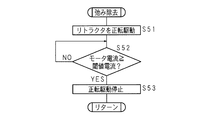
- FIG. 15 is a flowchart showing a processing procedure of the control unit 17 related to the slack removal of the seat belt 10.
- the control unit 17 drives the retractor 12 to rotate forward (step S51).
- the control unit 17 receives the signal output from the current detection unit 12i, and determines whether or not the motor current indicated by the received signal is greater than or equal to a predetermined threshold current (step S52). When it determines with it being less than a threshold current (step S52: NO), the control part 17 returns a process to step S52.
- step S52 When it determines with it being more than a threshold current (step S52: YES), the control part 17 stops the normal rotation drive of the retractor 12 (step S53), and complete
- the threshold current used in step S52 is preferably smaller than the threshold current used in step S35. In the process of step S52, it is sufficient if the slack of the seat belt 10 can be removed.
- step S ⁇ b> 11: NO when it is determined that the buckle switch 16 a is in the ON state (step S ⁇ b> 11: NO), or when the processing related to the slack removal is finished, the control unit 17 monitors the signal output from the buckle switch 16 a. Then, it is determined whether or not the buckle switch 16a is in an off state (step S17). When it determines with the buckle switch 16a not being in an OFF state by the process of step S11 and step S17 (step S17: NO), the control part 17 returns a process to step S17.
- step S17 When it is determined that the buckle switch 16a is in the OFF state (step S17: YES), that is, when the buckle 16 is attached to the tongue plate 15, the control unit 17 calls a subroutine to assist in storing the seat belt 10. This process is executed (step S18), and the process ends.
- the buckle switch 16a changes from the on state to the off state, the occupant A is expected to remove the seat belt 10 and get off the vehicle, so that the seat belt 10 is retracted to assist the storing of the seat belt 10.
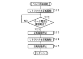
- FIG. 16 is a flowchart showing a processing procedure of the control unit 17 related to the belt storing assistance.
- the control unit 17 drives the retractor 12 to rotate forward (step S71).
- the rotational force of the motor 12d in the process related to the belt storing assistance is smaller than the rotational force of the motor 12d in step S32, and it is sufficient that at least the slack of the seat belt 10 is removed and accommodated in the retractor 12. That is, a rotational force that rotates the leecher 13 rearward against the urging force of the return spring 133 that urges the leecher 13 is unnecessary.
- the control unit 17 receives the signal output from the current detection unit 12i, and determines whether or not the motor current indicated by the received signal is equal to or greater than a predetermined threshold current (step S72). When it determines with it being less than a threshold current (step S72: NO), the control part 17 returns a process to step S72. When it determines with it being more than a threshold current (step S72: YES), the control part 17 stops the forward rotation drive of the retractor 12 (step S73). Then, the control unit 17 reversely drives the retractor 12 (step S74), stops the reverse drive after waiting for a predetermined time (step S75), and ends the processing related to the storage assist of the seat belt 10.
- the storage detection unit 18 when storing the leecher 13 by driving the motor 12d to rotate forward, the storage detection unit 18 is in an on state and the motor current threshold is predetermined. When the value is equal to or greater than the threshold value, the forward rotation drive of the retractor 12 is stopped and the reverse drive is performed. Therefore, when the occupant A removes the seat belt 10, the seat belt 10 remains caught on the arm or the like. The situation where it becomes difficult to pull out 10 can be prevented. Specifically, when an arm or the like is caught on the seat belt 10 while the leecher 13 is being stored, the seat belt 10 can be appropriately pulled back, and the clutch can be turned off. The seat belt 10 can be pulled out and the seat belt 10 caught on the arm or the like can be removed.
- the forward rotation drive of the retractor 12 is performed again, so that the forward drive of the retractor 12 is completed in a state where the storage of the reacher 13 is not completed. Can be avoided.
- the retractor 12 is driven forward again. Can be stored.
- the retractor 13 is stored such that the position of the reacher 13 is directly detected to control the rotation of the motor 12d, the seat belt 10 and the reacher 13 are detected by a rotation sensor provided in the retractor 12.
- the occupant protection device 1 can be configured more easily and at a lower cost than the configuration in which the storage state is determined and the motor 12d is driven.
Landscapes
- Engineering & Computer Science (AREA)
- Mechanical Engineering (AREA)
- Automotive Seat Belt Assembly (AREA)
- Emergency Lowering Means (AREA)
Abstract
Description
乗員は、シートベルトに挿通しているタングプレートを引っ張ることで収容されたシートベルトを引き出し、これを座席の傍らに設けたバックルに装着させることで、シートベルトを装着することができる。
また、モータ電流を検出して、モータの回転を停止させる構成も考えられるが、モータ電流が閾値電流以上となった場合、ベルト位置変更部材の格納が完了していないにも拘わらず、リトラクタ正転駆動が終了してしまうという問題がある。
更に、シートベルトを取り外す場合、乗員が降車するまではモータは反転駆動しないため、腕等にシートベルトが引っ掛かった場合、クラッチがオン状態のままであり、そのため、シートベルトを引き出すことが容易では無く、乗員は強い不快感を覚えるという問題があった。
図1は、本発明の実施の形態に係る乗員保護装置の構成を示した模式図である。本発明の乗員保護装置1は、いわゆる3点式であり、乗員Aを座席Cに拘束するためのシートベルト10と、センターピラーBの下部、座席Cの側方に配設されており、シートベルト10を引き出し可能に巻き取るリトラクタ12とを備える。
斯かる構成により、リーチャ13の基部131は、車室下部の固定板14に回動可能に軸支される。なお、図示した回動軸131bは一例であり、リーチャ13の回動によって、シートベルト10を前後移動させることができるよう軸支することができれば、他の構成であっても良い。また、回動軸131bは、固定板14に支持されているが、車体に対して前後回動可能であれば、他の部材に回動軸131bを支持させても良い。更に、リターンスプリング133は付勢部材の一例であり、これに限定されるものでは無い。付勢部材は、少なくともリーチャ13を車両の進行方側へ回動させる付勢力を該リーチャ13に与えることができる部材であれば良く、例えばコイルばね、トーションバー等でも良い。
また、リトラクタ12は、巻取軸12bをシートベルト10の巻取方向及び引出方向へ回転させるモータ12dと、モータ12dに流れる電流を検出し、検出した電流値を示す信号を後述の制御部17へ出力する電流検出部12iとを備えている。モータ12dは、モータ駆動部12eから供給された電流によって駆動する。モータ駆動部12eによるモータ12dの回転は、制御部17によって制御される。より具体的には、モータ駆動部12eは、PWM(Pulse Width Modulation)制御回路を有し、制御部17は、PWM制御信号をモータ駆動部12eへ出力することによって、モータ駆動部12eを構成するスイッチング素子をオンオフし、モータ12dを駆動させる。モータ12dの駆動電圧は例えば12Vである。巻取軸12bは、中心部から中心方向外側へ突出した軸部12cを有し、該軸部12cは動力伝達機構12gを介してモータ12dの駆動軸12fに接続されている。巻取軸12bは、動力伝達機構12gを介して伝達した駆動力によって、ベルト巻き取り方向へ回転する。
動力伝達機構12gは、モータ12dの出力軸の回転を、巻取軸12bに伝達するギアと、該ギアの回転方向を規制するクラッチとで構成される。モータ12dが正回転した場合、クラッチが動作し、モータ12dの駆動力が巻取軸12bに伝達し、巻取軸12bは、ベルト巻き取り方向へ回転する。モータ12dが逆回転した場合、クラッチが解除され、モータ12dの駆動力が巻取軸12bに伝達されない。
更に、リトラクタ12には、ガス発生剤式プリテンショナ12hが設けられている。ガス発生剤式プリテンショナ12hは、ガス発生剤と、該ガス発生剤を着火させる着火剤と、該ガス発生剤から発生したガスの圧力を巻取軸12bの回転力として該巻取軸12bに伝達する機構とを有する。車両の衝突が検知された場合、制御部17の制御に従って、着火剤に電流が流れ、ガス発生剤からガスが発生し、発生したガスの圧力によって、巻取軸12bがベルト巻取り方向に回転する。
更にまた、リトラクタ12は、引き出しロック機構を備える。引き出しロック機能は、例えばシートベルト10の引き出し加速度が所定加速度以上になった場合に、シートベルト10の引き出しをロックする機構である。
更にまた、リトラクタ12は、ロードリミッタ機構を備える。ロードリミッタ機構は、シートベルト10に加わる荷重が所定荷重以上になった場合、シートベルト10の引き出しがロックされていてもベルトが引き出され、前記荷重が所定荷重以上に上昇しないように構成されている。ロードリミッタ機構は、例えば、該巻取軸12bの途中に設けられたトーションバー部分で構成され、所定荷重以上の回転応力が加わると降伏して回転するように構成されている。
また、ドアが閉じている状態で、バックルスイッチ16aがオフ状態にあり、かつ車速が所定速度以上である場合、乗員Aが着座していないと予想されるため、リーチャ13を格納する。車両走行中にリーチャ13が前方に位置していると、走行車両の振動によってタングプレート15が車体内にぶつかり異音が発生するおそれがあるが、リーチャ13を格納することによって斯かる問題を回避することができる。また、座席Cに誰もすわっていないときには、リーチャ13を格納して、見た目を良くすることもできる。
上述の処理によって、リトラクタ12の正転駆動及び反転駆動を複数回実行することができ、リーチャ13の格納が完了していない状態でリトラクタ12の正転駆動が終了することを避けることができる。
なお、ステップS52で使用する閾値電流は、ステップS35で使用する閾値電流より小さい方が好ましい。ステップS52の処理では、シートベルト10の弛みを除去できれば十分である。
10 シートベルト
11 スルーアンカー
12 リトラクタ
12b 巻取軸
12d モータ
12e モータ駆動部
12i 電流検出部
13 リーチャ
14 固定板
14a ストッパ
15 タングプレート
16 バックル
16a バックルスイッチ
17 制御部
17a 記憶部
18 格納検出部
19 ドア開閉検出部
20 車速計
131a ブーツ
131b 回動軸
131c 支持要素
131d アンカープレート
132 プラスチックワッシャ
133 リターンスプリング
134 ワッシャ
135 ホールドプレート
A 乗員
B センターピラー
C 座席
Claims (4)
- 乗員を拘束保護するシートベルトの一端部が接続され、該シートベルトを巻き取る巻取軸と、
軸長方向を左右横方向とした回動軸で回動可能に支持されており、前記シートベルトの一部が接続され、該シートベルトの位置を車両の前後方向へ変更するベルト位置変更部材と、
該ベルト位置変更部材を前方へ回動させるよう付勢する付勢部材と、
前記ベルト位置変更部材が後方位置にあることを検出する位置検出部と、
前記巻取軸を前記シートベルトの巻取方向及び引出方向へ回転させるモータと、
該モータに流れる電流を検出する電流検出部と、
該電流検出部及び前記位置検出部の検出結果に基づいて、前記モータの回転を制御する制御部と
を備え、
前記制御部は、
前記モータが前記シートベルトの巻取方向へ回転していて、前記ベルト位置変更部材が後方位置に無く、且つ前記電流検出部にて検出された電流が所定電流値以上である場合、前記モータの回転方向を引出方向に変更するように構成してある
ことを特徴とする乗員保護装置。 - 前記制御部は、
前記モータを引出方向へ回転させ、所定時間経過後、前記モータを巻取方向へ回転させるように構成してある
ことを特徴とする請求項1に記載の乗員保護装置。 - 前記制御部は、
前記モータが巻取方向へ回転していて、前記ベルト位置変更部材が後方位置にある場合、前記モータの回転を停止させるように構成してある
ことを特徴とする請求項1又は請求項2に記載の乗員保護装置。 - 車両のドアの開閉を検出するドア開閉検出部と、
シートベルトに取り付けられたタングプレートと、
該タングプレートが装着されるバックルと、
該バックルに前記タングプレートが装着されているか否かを検出するバックルスイッチと
を備え、
前記制御部は、
前記ドア開閉検出部がドアの開状態を検出し、前記バックルスイッチがタングプレートの未装着を検出した場合、前記モータを巻取方向へ回転させるように構成してある
ことを特徴とする請求項1乃至請求項3のいずれか一つに記載の乗員保護装置。
Priority Applications (5)
| Application Number | Priority Date | Filing Date | Title |
|---|---|---|---|
| EP11789553.2A EP2578456B1 (en) | 2010-06-03 | 2011-04-20 | Occupant protection device |
| CN201180024186.9A CN102892643B (zh) | 2010-06-03 | 2011-04-20 | 驾乘者保护装置 |
| US13/701,667 US8590658B2 (en) | 2010-06-03 | 2011-04-20 | Occupant protection device |
| JP2012518290A JP5468134B2 (ja) | 2010-06-03 | 2011-04-20 | 乗員保護装置 |
| KR1020127031645A KR101432660B1 (ko) | 2010-06-03 | 2011-04-20 | 탑승자 보호장치 |
Applications Claiming Priority (2)
| Application Number | Priority Date | Filing Date | Title |
|---|---|---|---|
| JP2010128170 | 2010-06-03 | ||
| JP2010-128170 | 2010-06-03 |
Publications (1)
| Publication Number | Publication Date |
|---|---|
| WO2011152144A1 true WO2011152144A1 (ja) | 2011-12-08 |
Family
ID=45066528
Family Applications (1)
| Application Number | Title | Priority Date | Filing Date |
|---|---|---|---|
| PCT/JP2011/059695 Ceased WO2011152144A1 (ja) | 2010-06-03 | 2011-04-20 | 乗員保護装置 |
Country Status (6)
| Country | Link |
|---|---|
| US (1) | US8590658B2 (ja) |
| EP (1) | EP2578456B1 (ja) |
| JP (1) | JP5468134B2 (ja) |
| KR (1) | KR101432660B1 (ja) |
| CN (1) | CN102892643B (ja) |
| WO (1) | WO2011152144A1 (ja) |
Cited By (2)
| Publication number | Priority date | Publication date | Assignee | Title |
|---|---|---|---|---|
| CN103723110A (zh) * | 2012-10-16 | 2014-04-16 | 本田技研工业株式会社 | 座椅安全带装置 |
| CN106553614A (zh) * | 2016-11-25 | 2017-04-05 | 奇瑞商用车(安徽)有限公司 | 安全带装置及具有其的汽车 |
Families Citing this family (6)
| Publication number | Priority date | Publication date | Assignee | Title |
|---|---|---|---|---|
| DE102011011425A1 (de) * | 2011-02-16 | 2012-08-16 | Trw Automotive Gmbh | Gurtbandfänger |
| JP5602253B2 (ja) * | 2013-01-09 | 2014-10-08 | 本田技研工業株式会社 | シートベルト装置 |
| JP2014148270A (ja) * | 2013-02-01 | 2014-08-21 | Autoliv Development Ab | シートベルト装置 |
| JP6630486B2 (ja) * | 2015-04-14 | 2020-01-15 | トピー工業株式会社 | ケーブルシステム |
| JP6791023B2 (ja) * | 2017-06-06 | 2020-11-25 | トヨタ自動車株式会社 | シートベルト制御装置 |
| US20190256039A1 (en) * | 2018-02-20 | 2019-08-22 | GM Global Technology Operations LLC | Systems and methods for a self-aligning restraint system |
Citations (4)
| Publication number | Priority date | Publication date | Assignee | Title |
|---|---|---|---|---|
| JP2004255994A (ja) * | 2003-02-26 | 2004-09-16 | Toyota Motor Corp | 車両用シートベルト装置 |
| JP2009040323A (ja) | 2007-08-10 | 2009-02-26 | Takata Corp | シートベルト装置 |
| JP2010023609A (ja) * | 2008-07-17 | 2010-02-04 | Honda Motor Co Ltd | 車両のシートベルト装置 |
| JP2010120603A (ja) * | 2008-11-21 | 2010-06-03 | Takata Corp | シートベルト装置 |
Family Cites Families (13)
| Publication number | Priority date | Publication date | Assignee | Title |
|---|---|---|---|---|
| DE4031257A1 (de) * | 1990-10-04 | 1992-04-09 | Bosch Gmbh Robert | Vorrichtung zum betreiben von elektromotorisch angetriebenen teilen |
| US5358310A (en) * | 1992-09-17 | 1994-10-25 | Tachi-S. Co., Ltd. | Seat belt device in an automotive seat |
| JPH10278716A (ja) * | 1997-04-02 | 1998-10-20 | Honda Motor Co Ltd | シートベルト装置 |
| CN100480108C (zh) * | 2003-11-27 | 2009-04-22 | 奥托立夫开发公司 | 安全带用卷取装置 |
| US7407193B2 (en) * | 2004-03-18 | 2008-08-05 | Takata Corporation | Seat belt buckle |
| JP4679125B2 (ja) * | 2004-12-06 | 2011-04-27 | タカタ株式会社 | シートベルト装置 |
| JP2007062421A (ja) * | 2005-08-29 | 2007-03-15 | Takata Corp | シートベルト装置、車両 |
| JP2007118776A (ja) * | 2005-10-28 | 2007-05-17 | Takata Corp | シートベルトのバックル装置及びシートベルト装置 |
| JP2007145079A (ja) * | 2005-11-24 | 2007-06-14 | Takata Corp | シートベルトリトラクタ、シートベルト装置、シートベルト装置付車両 |
| JP5121213B2 (ja) * | 2006-11-22 | 2013-01-16 | タカタ株式会社 | シートベルト装置 |
| JP5215549B2 (ja) * | 2006-11-24 | 2013-06-19 | タカタ株式会社 | シートベルト巻き取り装置 |
| JP4890287B2 (ja) * | 2007-02-07 | 2012-03-07 | 本田技研工業株式会社 | 車両のシートベルト装置 |
| KR101305812B1 (ko) * | 2011-10-05 | 2013-09-06 | 아우토리브 디벨롭먼트 아베 | 차량용 시트벨트의 웨빙가이드 회전장치 및 그 회전 제어방법 |
-
2011
- 2011-04-20 EP EP11789553.2A patent/EP2578456B1/en active Active
- 2011-04-20 KR KR1020127031645A patent/KR101432660B1/ko active Active
- 2011-04-20 JP JP2012518290A patent/JP5468134B2/ja active Active
- 2011-04-20 WO PCT/JP2011/059695 patent/WO2011152144A1/ja not_active Ceased
- 2011-04-20 CN CN201180024186.9A patent/CN102892643B/zh active Active
- 2011-04-20 US US13/701,667 patent/US8590658B2/en active Active
Patent Citations (4)
| Publication number | Priority date | Publication date | Assignee | Title |
|---|---|---|---|---|
| JP2004255994A (ja) * | 2003-02-26 | 2004-09-16 | Toyota Motor Corp | 車両用シートベルト装置 |
| JP2009040323A (ja) | 2007-08-10 | 2009-02-26 | Takata Corp | シートベルト装置 |
| JP2010023609A (ja) * | 2008-07-17 | 2010-02-04 | Honda Motor Co Ltd | 車両のシートベルト装置 |
| JP2010120603A (ja) * | 2008-11-21 | 2010-06-03 | Takata Corp | シートベルト装置 |
Non-Patent Citations (1)
| Title |
|---|
| See also references of EP2578456A4 |
Cited By (4)
| Publication number | Priority date | Publication date | Assignee | Title |
|---|---|---|---|---|
| CN103723110A (zh) * | 2012-10-16 | 2014-04-16 | 本田技研工业株式会社 | 座椅安全带装置 |
| DE102013220328A1 (de) | 2012-10-16 | 2014-04-17 | Honda Motor Co., Ltd. | Sitzgurtvorrichtung |
| US8844667B2 (en) | 2012-10-16 | 2014-09-30 | Honda Motor Co., Ltd. | Seat belt apparatus |
| CN106553614A (zh) * | 2016-11-25 | 2017-04-05 | 奇瑞商用车(安徽)有限公司 | 安全带装置及具有其的汽车 |
Also Published As
| Publication number | Publication date |
|---|---|
| JP5468134B2 (ja) | 2014-04-09 |
| KR101432660B1 (ko) | 2014-08-21 |
| US20130162002A1 (en) | 2013-06-27 |
| US8590658B2 (en) | 2013-11-26 |
| EP2578456A4 (en) | 2013-06-05 |
| EP2578456B1 (en) | 2014-05-28 |
| CN102892643A (zh) | 2013-01-23 |
| EP2578456A1 (en) | 2013-04-10 |
| CN102892643B (zh) | 2015-03-25 |
| KR20130027525A (ko) | 2013-03-15 |
| JPWO2011152144A1 (ja) | 2013-07-25 |
Similar Documents
| Publication | Publication Date | Title |
|---|---|---|
| JP5468134B2 (ja) | 乗員保護装置 | |
| US7661504B2 (en) | Vehicle seatbelt apparatus | |
| US20110270493A1 (en) | Seat-belt-retractor control device and seat belt device having the same | |
| JP4705058B2 (ja) | モータ駆動シートベルト装置 | |
| JP4570141B2 (ja) | シートベルト巻き取り装置及びシートベルト装置 | |
| US7726693B2 (en) | Motor retractor and drive control thereof | |
| CN1891538B (zh) | 安全带卷收器、安全带装置和带安全带装置的车辆 | |
| JP5460213B2 (ja) | シートベルト装置 | |
| EP1324901A1 (en) | A safety-belt arrangement | |
| JP5704058B2 (ja) | 車両用乗員拘束装置及びその制御方法 | |
| JP2009280093A (ja) | シートベルトリトラクタ | |
| JP4501658B2 (ja) | 車両の乗員膝部拘束装置および乗員膝部拘束方法 | |
| JP4381939B2 (ja) | ウエビング巻取装置 | |
| JP4916393B2 (ja) | 車両のシートベルト装置 | |
| JP2011230690A (ja) | シートベルトリトラクタの制御装置およびこれを備えたシートベルト装置 | |
| JP4990849B2 (ja) | 車両のシートベルト装置 | |
| JP5531051B2 (ja) | シートベルトリトラクタ | |
| JP4722619B2 (ja) | 車両のシートベルト装置 | |
| JP2008296674A (ja) | 車両のシートベルト装置 | |
| JP4979747B2 (ja) | シートベルト装置 | |
| JP5650624B2 (ja) | シートベルトの制御装置 | |
| JP6087059B2 (ja) | シートベルトの制御装置 | |
| JPS5977941A (ja) | シ−トベルトリトラクタ | |
| JP2013082325A (ja) | シートベルトの制御装置 | |
| JP2006160056A (ja) | ウエビング巻取装置及び3点式シートベルト装置 |
Legal Events
| Date | Code | Title | Description |
|---|---|---|---|
| WWE | Wipo information: entry into national phase |
Ref document number: 201180024186.9 Country of ref document: CN |
|
| 121 | Ep: the epo has been informed by wipo that ep was designated in this application |
Ref document number: 11789553 Country of ref document: EP Kind code of ref document: A1 |
|
| WWE | Wipo information: entry into national phase |
Ref document number: 2012518290 Country of ref document: JP |
|
| ENP | Entry into the national phase |
Ref document number: 20127031645 Country of ref document: KR Kind code of ref document: A |
|
| NENP | Non-entry into the national phase |
Ref country code: DE |
|
| WWE | Wipo information: entry into national phase |
Ref document number: 13701667 Country of ref document: US |
|
| WWE | Wipo information: entry into national phase |
Ref document number: 2011789553 Country of ref document: EP |