WO2011152165A1 - 排気ガス浄化システム - Google Patents
排気ガス浄化システム Download PDFInfo
- Publication number
- WO2011152165A1 WO2011152165A1 PCT/JP2011/060464 JP2011060464W WO2011152165A1 WO 2011152165 A1 WO2011152165 A1 WO 2011152165A1 JP 2011060464 W JP2011060464 W JP 2011060464W WO 2011152165 A1 WO2011152165 A1 WO 2011152165A1
- Authority
- WO
- WIPO (PCT)
- Prior art keywords
- regeneration
- exhaust gas
- mode
- engine
- gas purification
- Prior art date
- Legal status (The legal status is an assumption and is not a legal conclusion. Google has not performed a legal analysis and makes no representation as to the accuracy of the status listed.)
- Ceased
Links
Images










Classifications
-
- F—MECHANICAL ENGINEERING; LIGHTING; HEATING; WEAPONS; BLASTING
- F01—MACHINES OR ENGINES IN GENERAL; ENGINE PLANTS IN GENERAL; STEAM ENGINES
- F01N—GAS-FLOW SILENCERS OR EXHAUST APPARATUS FOR MACHINES OR ENGINES IN GENERAL; GAS-FLOW SILENCERS OR EXHAUST APPARATUS FOR INTERNAL-COMBUSTION ENGINES
- F01N11/00—Monitoring or diagnostic devices for exhaust-gas treatment apparatus
-
- F—MECHANICAL ENGINEERING; LIGHTING; HEATING; WEAPONS; BLASTING
- F01—MACHINES OR ENGINES IN GENERAL; ENGINE PLANTS IN GENERAL; STEAM ENGINES
- F01N—GAS-FLOW SILENCERS OR EXHAUST APPARATUS FOR MACHINES OR ENGINES IN GENERAL; GAS-FLOW SILENCERS OR EXHAUST APPARATUS FOR INTERNAL-COMBUSTION ENGINES
- F01N3/00—Exhaust or silencing apparatus having means for purifying, rendering innocuous, or otherwise treating exhaust
-
- F—MECHANICAL ENGINEERING; LIGHTING; HEATING; WEAPONS; BLASTING
- F01—MACHINES OR ENGINES IN GENERAL; ENGINE PLANTS IN GENERAL; STEAM ENGINES
- F01N—GAS-FLOW SILENCERS OR EXHAUST APPARATUS FOR MACHINES OR ENGINES IN GENERAL; GAS-FLOW SILENCERS OR EXHAUST APPARATUS FOR INTERNAL-COMBUSTION ENGINES
- F01N3/00—Exhaust or silencing apparatus having means for purifying, rendering innocuous, or otherwise treating exhaust
- F01N3/02—Exhaust or silencing apparatus having means for purifying, rendering innocuous, or otherwise treating exhaust for cooling, or for removing solid constituents of, exhaust
-
- F—MECHANICAL ENGINEERING; LIGHTING; HEATING; WEAPONS; BLASTING
- F01—MACHINES OR ENGINES IN GENERAL; ENGINE PLANTS IN GENERAL; STEAM ENGINES
- F01N—GAS-FLOW SILENCERS OR EXHAUST APPARATUS FOR MACHINES OR ENGINES IN GENERAL; GAS-FLOW SILENCERS OR EXHAUST APPARATUS FOR INTERNAL-COMBUSTION ENGINES
- F01N3/00—Exhaust or silencing apparatus having means for purifying, rendering innocuous, or otherwise treating exhaust
- F01N3/02—Exhaust or silencing apparatus having means for purifying, rendering innocuous, or otherwise treating exhaust for cooling, or for removing solid constituents of, exhaust
- F01N3/021—Exhaust or silencing apparatus having means for purifying, rendering innocuous, or otherwise treating exhaust for cooling, or for removing solid constituents of, exhaust by means of filters
- F01N3/023—Exhaust or silencing apparatus having means for purifying, rendering innocuous, or otherwise treating exhaust for cooling, or for removing solid constituents of, exhaust by means of filters using means for regenerating the filters, e.g. by burning trapped particles
-
- F—MECHANICAL ENGINEERING; LIGHTING; HEATING; WEAPONS; BLASTING
- F01—MACHINES OR ENGINES IN GENERAL; ENGINE PLANTS IN GENERAL; STEAM ENGINES
- F01N—GAS-FLOW SILENCERS OR EXHAUST APPARATUS FOR MACHINES OR ENGINES IN GENERAL; GAS-FLOW SILENCERS OR EXHAUST APPARATUS FOR INTERNAL-COMBUSTION ENGINES
- F01N3/00—Exhaust or silencing apparatus having means for purifying, rendering innocuous, or otherwise treating exhaust
- F01N3/02—Exhaust or silencing apparatus having means for purifying, rendering innocuous, or otherwise treating exhaust for cooling, or for removing solid constituents of, exhaust
- F01N3/021—Exhaust or silencing apparatus having means for purifying, rendering innocuous, or otherwise treating exhaust for cooling, or for removing solid constituents of, exhaust by means of filters
- F01N3/023—Exhaust or silencing apparatus having means for purifying, rendering innocuous, or otherwise treating exhaust for cooling, or for removing solid constituents of, exhaust by means of filters using means for regenerating the filters, e.g. by burning trapped particles
- F01N3/025—Exhaust or silencing apparatus having means for purifying, rendering innocuous, or otherwise treating exhaust for cooling, or for removing solid constituents of, exhaust by means of filters using means for regenerating the filters, e.g. by burning trapped particles using fuel burner or by adding fuel to exhaust
- F01N3/0253—Exhaust or silencing apparatus having means for purifying, rendering innocuous, or otherwise treating exhaust for cooling, or for removing solid constituents of, exhaust by means of filters using means for regenerating the filters, e.g. by burning trapped particles using fuel burner or by adding fuel to exhaust adding fuel to exhaust gases
-
- F—MECHANICAL ENGINEERING; LIGHTING; HEATING; WEAPONS; BLASTING
- F01—MACHINES OR ENGINES IN GENERAL; ENGINE PLANTS IN GENERAL; STEAM ENGINES
- F01N—GAS-FLOW SILENCERS OR EXHAUST APPARATUS FOR MACHINES OR ENGINES IN GENERAL; GAS-FLOW SILENCERS OR EXHAUST APPARATUS FOR INTERNAL-COMBUSTION ENGINES
- F01N3/00—Exhaust or silencing apparatus having means for purifying, rendering innocuous, or otherwise treating exhaust
- F01N3/02—Exhaust or silencing apparatus having means for purifying, rendering innocuous, or otherwise treating exhaust for cooling, or for removing solid constituents of, exhaust
- F01N3/021—Exhaust or silencing apparatus having means for purifying, rendering innocuous, or otherwise treating exhaust for cooling, or for removing solid constituents of, exhaust by means of filters
- F01N3/033—Exhaust or silencing apparatus having means for purifying, rendering innocuous, or otherwise treating exhaust for cooling, or for removing solid constituents of, exhaust by means of filters in combination with other devices
- F01N3/0335—Exhaust or silencing apparatus having means for purifying, rendering innocuous, or otherwise treating exhaust for cooling, or for removing solid constituents of, exhaust by means of filters in combination with other devices with exhaust silencers in a single housing
-
- F—MECHANICAL ENGINEERING; LIGHTING; HEATING; WEAPONS; BLASTING
- F01—MACHINES OR ENGINES IN GENERAL; ENGINE PLANTS IN GENERAL; STEAM ENGINES
- F01N—GAS-FLOW SILENCERS OR EXHAUST APPARATUS FOR MACHINES OR ENGINES IN GENERAL; GAS-FLOW SILENCERS OR EXHAUST APPARATUS FOR INTERNAL-COMBUSTION ENGINES
- F01N3/00—Exhaust or silencing apparatus having means for purifying, rendering innocuous, or otherwise treating exhaust
- F01N3/02—Exhaust or silencing apparatus having means for purifying, rendering innocuous, or otherwise treating exhaust for cooling, or for removing solid constituents of, exhaust
- F01N3/021—Exhaust or silencing apparatus having means for purifying, rendering innocuous, or otherwise treating exhaust for cooling, or for removing solid constituents of, exhaust by means of filters
- F01N3/033—Exhaust or silencing apparatus having means for purifying, rendering innocuous, or otherwise treating exhaust for cooling, or for removing solid constituents of, exhaust by means of filters in combination with other devices
- F01N3/035—Exhaust or silencing apparatus having means for purifying, rendering innocuous, or otherwise treating exhaust for cooling, or for removing solid constituents of, exhaust by means of filters in combination with other devices with catalytic reactors
-
- F—MECHANICAL ENGINEERING; LIGHTING; HEATING; WEAPONS; BLASTING
- F01—MACHINES OR ENGINES IN GENERAL; ENGINE PLANTS IN GENERAL; STEAM ENGINES
- F01N—GAS-FLOW SILENCERS OR EXHAUST APPARATUS FOR MACHINES OR ENGINES IN GENERAL; GAS-FLOW SILENCERS OR EXHAUST APPARATUS FOR INTERNAL-COMBUSTION ENGINES
- F01N9/00—Electrical control of exhaust gas treating apparatus
- F01N9/002—Electrical control of exhaust gas treating apparatus of filter regeneration
-
- F—MECHANICAL ENGINEERING; LIGHTING; HEATING; WEAPONS; BLASTING
- F02—COMBUSTION ENGINES; HOT-GAS OR COMBUSTION-PRODUCT ENGINE PLANTS
- F02D—CONTROLLING COMBUSTION ENGINES
- F02D41/00—Electrical control of supply of combustible mixture or its constituents
- F02D41/02—Circuit arrangements for generating control signals
- F02D41/021—Introducing corrections for particular conditions exterior to the engine
- F02D41/0235—Introducing corrections for particular conditions exterior to the engine in relation with the state of the exhaust gas treating apparatus
- F02D41/027—Introducing corrections for particular conditions exterior to the engine in relation with the state of the exhaust gas treating apparatus to purge or regenerate the exhaust gas treating apparatus
- F02D41/029—Introducing corrections for particular conditions exterior to the engine in relation with the state of the exhaust gas treating apparatus to purge or regenerate the exhaust gas treating apparatus the exhaust gas treating apparatus being a particulate filter
-
- F—MECHANICAL ENGINEERING; LIGHTING; HEATING; WEAPONS; BLASTING
- F02—COMBUSTION ENGINES; HOT-GAS OR COMBUSTION-PRODUCT ENGINE PLANTS
- F02D—CONTROLLING COMBUSTION ENGINES
- F02D41/00—Electrical control of supply of combustible mixture or its constituents
- F02D41/22—Safety or indicating devices for abnormal conditions
-
- F—MECHANICAL ENGINEERING; LIGHTING; HEATING; WEAPONS; BLASTING
- F02—COMBUSTION ENGINES; HOT-GAS OR COMBUSTION-PRODUCT ENGINE PLANTS
- F02D—CONTROLLING COMBUSTION ENGINES
- F02D41/00—Electrical control of supply of combustible mixture or its constituents
- F02D41/30—Controlling fuel injection
- F02D41/38—Controlling fuel injection of the high pressure type
- F02D41/40—Controlling fuel injection of the high pressure type with means for controlling injection timing or duration
- F02D41/402—Multiple injections
- F02D41/405—Multiple injections with post injections
-
- F—MECHANICAL ENGINEERING; LIGHTING; HEATING; WEAPONS; BLASTING
- F01—MACHINES OR ENGINES IN GENERAL; ENGINE PLANTS IN GENERAL; STEAM ENGINES
- F01N—GAS-FLOW SILENCERS OR EXHAUST APPARATUS FOR MACHINES OR ENGINES IN GENERAL; GAS-FLOW SILENCERS OR EXHAUST APPARATUS FOR INTERNAL-COMBUSTION ENGINES
- F01N2240/00—Combination or association of two or more different exhaust treating devices, or of at least one such device with an auxiliary device, not covered by indexing codes F01N2230/00 or F01N2250/00, one of the devices being
- F01N2240/36—Combination or association of two or more different exhaust treating devices, or of at least one such device with an auxiliary device, not covered by indexing codes F01N2230/00 or F01N2250/00, one of the devices being an exhaust flap
-
- F—MECHANICAL ENGINEERING; LIGHTING; HEATING; WEAPONS; BLASTING
- F01—MACHINES OR ENGINES IN GENERAL; ENGINE PLANTS IN GENERAL; STEAM ENGINES
- F01N—GAS-FLOW SILENCERS OR EXHAUST APPARATUS FOR MACHINES OR ENGINES IN GENERAL; GAS-FLOW SILENCERS OR EXHAUST APPARATUS FOR INTERNAL-COMBUSTION ENGINES
- F01N3/00—Exhaust or silencing apparatus having means for purifying, rendering innocuous, or otherwise treating exhaust
- F01N3/08—Exhaust or silencing apparatus having means for purifying, rendering innocuous, or otherwise treating exhaust for rendering innocuous
- F01N3/10—Exhaust or silencing apparatus having means for purifying, rendering innocuous, or otherwise treating exhaust for rendering innocuous by thermal or catalytic conversion of noxious components of exhaust
- F01N3/24—Exhaust or silencing apparatus having means for purifying, rendering innocuous, or otherwise treating exhaust for rendering innocuous by thermal or catalytic conversion of noxious components of exhaust characterised by constructional aspects of converting apparatus
- F01N3/28—Construction of catalytic reactors
- F01N3/2882—Catalytic reactors combined or associated with other devices, e.g. exhaust silencers or other exhaust purification devices
- F01N3/2885—Catalytic reactors combined or associated with other devices, e.g. exhaust silencers or other exhaust purification devices with exhaust silencers in a single housing
-
- F—MECHANICAL ENGINEERING; LIGHTING; HEATING; WEAPONS; BLASTING
- F02—COMBUSTION ENGINES; HOT-GAS OR COMBUSTION-PRODUCT ENGINE PLANTS
- F02D—CONTROLLING COMBUSTION ENGINES
- F02D41/00—Electrical control of supply of combustible mixture or its constituents
- F02D41/22—Safety or indicating devices for abnormal conditions
- F02D2041/227—Limping Home, i.e. taking specific engine control measures at abnormal conditions
-
- F—MECHANICAL ENGINEERING; LIGHTING; HEATING; WEAPONS; BLASTING
- F02—COMBUSTION ENGINES; HOT-GAS OR COMBUSTION-PRODUCT ENGINE PLANTS
- F02D—CONTROLLING COMBUSTION ENGINES
- F02D2200/00—Input parameters for engine control
- F02D2200/02—Input parameters for engine control the parameters being related to the engine
- F02D2200/08—Exhaust gas treatment apparatus parameters
- F02D2200/0812—Particle filter loading
-
- F—MECHANICAL ENGINEERING; LIGHTING; HEATING; WEAPONS; BLASTING
- F02—COMBUSTION ENGINES; HOT-GAS OR COMBUSTION-PRODUCT ENGINE PLANTS
- F02D—CONTROLLING COMBUSTION ENGINES
- F02D2200/00—Input parameters for engine control
- F02D2200/60—Input parameters for engine control said parameters being related to the driver demands or status
- F02D2200/604—Engine control mode selected by driver, e.g. to manually start particle filter regeneration or to select driving style
-
- F—MECHANICAL ENGINEERING; LIGHTING; HEATING; WEAPONS; BLASTING
- F02—COMBUSTION ENGINES; HOT-GAS OR COMBUSTION-PRODUCT ENGINE PLANTS
- F02D—CONTROLLING COMBUSTION ENGINES
- F02D2250/00—Engine control related to specific problems or objectives
- F02D2250/11—Oil dilution, i.e. prevention thereof or special controls according thereto
-
- F—MECHANICAL ENGINEERING; LIGHTING; HEATING; WEAPONS; BLASTING
- F02—COMBUSTION ENGINES; HOT-GAS OR COMBUSTION-PRODUCT ENGINE PLANTS
- F02D—CONTROLLING COMBUSTION ENGINES
- F02D41/00—Electrical control of supply of combustible mixture or its constituents
- F02D41/02—Circuit arrangements for generating control signals
- F02D41/021—Introducing corrections for particular conditions exterior to the engine
-
- F—MECHANICAL ENGINEERING; LIGHTING; HEATING; WEAPONS; BLASTING
- F02—COMBUSTION ENGINES; HOT-GAS OR COMBUSTION-PRODUCT ENGINE PLANTS
- F02D—CONTROLLING COMBUSTION ENGINES
- F02D41/00—Electrical control of supply of combustible mixture or its constituents
- F02D41/02—Circuit arrangements for generating control signals
- F02D41/021—Introducing corrections for particular conditions exterior to the engine
- F02D41/0235—Introducing corrections for particular conditions exterior to the engine in relation with the state of the exhaust gas treating apparatus
-
- F—MECHANICAL ENGINEERING; LIGHTING; HEATING; WEAPONS; BLASTING
- F02—COMBUSTION ENGINES; HOT-GAS OR COMBUSTION-PRODUCT ENGINE PLANTS
- F02D—CONTROLLING COMBUSTION ENGINES
- F02D41/00—Electrical control of supply of combustible mixture or its constituents
- F02D41/02—Circuit arrangements for generating control signals
- F02D41/021—Introducing corrections for particular conditions exterior to the engine
- F02D41/0235—Introducing corrections for particular conditions exterior to the engine in relation with the state of the exhaust gas treating apparatus
- F02D41/024—Introducing corrections for particular conditions exterior to the engine in relation with the state of the exhaust gas treating apparatus to increase temperature of the exhaust gas treating apparatus
- F02D41/0245—Introducing corrections for particular conditions exterior to the engine in relation with the state of the exhaust gas treating apparatus to increase temperature of the exhaust gas treating apparatus by increasing temperature of the exhaust gas leaving the engine
-
- F—MECHANICAL ENGINEERING; LIGHTING; HEATING; WEAPONS; BLASTING
- F02—COMBUSTION ENGINES; HOT-GAS OR COMBUSTION-PRODUCT ENGINE PLANTS
- F02D—CONTROLLING COMBUSTION ENGINES
- F02D41/00—Electrical control of supply of combustible mixture or its constituents
- F02D41/02—Circuit arrangements for generating control signals
- F02D41/021—Introducing corrections for particular conditions exterior to the engine
- F02D41/0235—Introducing corrections for particular conditions exterior to the engine in relation with the state of the exhaust gas treating apparatus
- F02D41/024—Introducing corrections for particular conditions exterior to the engine in relation with the state of the exhaust gas treating apparatus to increase temperature of the exhaust gas treating apparatus
- F02D41/025—Introducing corrections for particular conditions exterior to the engine in relation with the state of the exhaust gas treating apparatus to increase temperature of the exhaust gas treating apparatus by changing the composition of the exhaust gas, e.g. for exothermic reaction on exhaust gas treating apparatus
-
- F—MECHANICAL ENGINEERING; LIGHTING; HEATING; WEAPONS; BLASTING
- F02—COMBUSTION ENGINES; HOT-GAS OR COMBUSTION-PRODUCT ENGINE PLANTS
- F02D—CONTROLLING COMBUSTION ENGINES
- F02D41/00—Electrical control of supply of combustible mixture or its constituents
- F02D41/02—Circuit arrangements for generating control signals
- F02D41/04—Introducing corrections for particular operating conditions
- F02D41/08—Introducing corrections for particular operating conditions for idling
-
- Y—GENERAL TAGGING OF NEW TECHNOLOGICAL DEVELOPMENTS; GENERAL TAGGING OF CROSS-SECTIONAL TECHNOLOGIES SPANNING OVER SEVERAL SECTIONS OF THE IPC; TECHNICAL SUBJECTS COVERED BY FORMER USPC CROSS-REFERENCE ART COLLECTIONS [XRACs] AND DIGESTS
- Y02—TECHNOLOGIES OR APPLICATIONS FOR MITIGATION OR ADAPTATION AGAINST CLIMATE CHANGE
- Y02T—CLIMATE CHANGE MITIGATION TECHNOLOGIES RELATED TO TRANSPORTATION
- Y02T10/00—Road transport of goods or passengers
- Y02T10/10—Internal combustion engine [ICE] based vehicles
- Y02T10/40—Engine management systems
Definitions
- the present invention relates to an exhaust gas purification system for an engine mounted on a work machine such as a construction machine, an agricultural machine, or an engine generator.
- DPF diesel particulate filter
- PM particulate matter
- JP 2000-145430 A Japanese Patent Laid-Open No. 2003-27922
- the engine is mounted on a wide variety of working machines such as construction machines, agricultural machines, and engine generators.
- working machines such as construction machines, agricultural machines, and engine generators.
- the DPF purification capacity does not sufficiently recover (when regeneration is insufficient).
- the engine with DPF is of the common rail type (the fuel injection device is of the common rail type)
- the DPF regeneration is promoted by aggressive heating in which fuel is supplied into the DPF and burned by post injection. It is possible.
- the present invention has a technical problem to provide an exhaust gas purification system that has been improved by examining the current situation.
- the invention of claim 1 includes an exhaust gas purifying device disposed in an exhaust path of a common rail engine, and can execute a plurality of regeneration modes for burning and removing particulate matter accumulated in the exhaust gas purifying device.
- the exhaust gas purification system is configured regardless of the clogged state of the exhaust gas purification device.
- the fuel cell has an initialization regeneration mode in which fuel is supplied into the exhaust gas purification device by post injection.
- a regeneration notice means for calling attention for prompting the execution of each regeneration mode, and a regeneration permission input permitting the execution of each regeneration mode. And when the reproduction permission input means is in a non-operating state under the operation of the reproduction notice means, the initialization reproduction mode is not executed.
- the regeneration notice means when the non-operation state of the regeneration permission input means continues for a predetermined standing time or longer, performs the initialization regeneration. It is configured to operate in a warning mode that is different from the mode of operation that prompts execution of the mode.
- the warning mode is used after the power is restored. In other words, the operation of the reproduction notice means is resumed.
- the exhaust gas purification system further includes a traveling system operation unit that operates a traveling system of a work machine on which the engine is mounted.
- the exhaust gas purification is performed by post-injection by performing the permission operation of the regeneration permission input unit and the operation of the traveling system operation unit corresponding to the traveling stop state of the work implement.
- the system is configured to shift to an emergency regeneration mode in which it is supplied into the apparatus and the engine speed is maintained at a predetermined value.
- the exhaust gas purification device disposed in the exhaust path of the common rail engine is provided, and a plurality of regeneration modes for burning and removing particulate matter accumulated in the exhaust gas purification device can be executed.
- the exhaust gas purification system configured as described above is concerned with the clogged state of the exhaust gas purification device when the cumulative driving time of the engine exceeds a preset set time. Since there is an initialization regeneration mode in which fuel is supplied into the exhaust gas purification device by post injection, when the engine is driven cumulatively for a long time, the operator does not perform the setting operation one by one. However, the initialization regeneration mode can be executed to forcibly and efficiently remove the particulate matter in the exhaust gas purification device.
- the execution frequency of the forced regeneration mode in other words, the post injection execution frequency can be lowered. Therefore, while the exhaust gas purifying device can be efficiently initialized and regenerated, it is possible to suppress deterioration in fuel consumption and to suppress deterioration in engine durability due to engine oil dilution.
- a playback notice means for calling attention for prompting execution of each of the playback modes
- a playback permission input means for permitting execution of each of the playback modes.
- the regeneration permission input means is in a non-operating state under the operation of the engine, it is configured not to execute the initialization regeneration mode. Execution of the initialization regeneration mode (regeneration operation of the exhaust gas purification device) can be prohibited. For this reason, the initialization reproduction mode is not executed in a state that the operator does not expect at all, and there is an effect that the operator can smoothly perform the detailed work that is performed by relying on the engine sound. That is, it is possible to eliminate the disadvantages of the regeneration operation of the exhaust gas purification device that may hinder the precise operation.
- the warning notice mode is different from the operation mode in which the reproduction notice means prompts the execution of the initialization reproduction mode. Since the exhaust gas purification device needs to be regenerated, the exhaust gas purification device may be left as it is for a long time, and the particulate matter in the exhaust gas purification device may increase to an over-deposited state. When the value is high, the operator's attention can be drawn in a warning mode different from the operation mode that prompts the execution of the initialization regeneration mode. Therefore, it is possible to prevent the particulate matter from being excessively deposited (and thus runaway combustion).
- the operation of the reproduction notification unit is resumed in the warning mode after the power is restored. Therefore, there is an effect that the possibility of using the exhaust gas purification device as it is in a state where the exhaust gas purification device is not sufficiently regenerated can be surely avoided.
- a fifth aspect of the present invention it is provided with travel system operation means for operating a travel system of a work machine equipped with the engine, and when the regeneration notice means operates in the warning mode, the regeneration permission after that Fuel is supplied into the exhaust gas purifier by post-injection and the engine rotation speed is set to a predetermined value by the permission operation of the input means and the operation of the traveling system operation means corresponding to the traveling stop state of the work implement. Since it is configured to shift to the emergency regeneration mode to be maintained, the transition to the emergency regeneration mode can be prohibited unless the operator intentionally stops the traveling of the work implement and various operations. For this reason, in the emergency regeneration mode in which the engine rotation speed is significantly increased, for example, it is possible to reliably avoid the occurrence of an unexpected situation in which the working machine is accelerated rapidly.
- the engine 70 is a four-cylinder type diesel engine, and includes a cylinder block 75 having a cylinder head 72 fastened on the upper surface.
- An intake manifold 73 is connected to one side of the cylinder head 72, and an exhaust manifold 71 is connected to the other side.
- a common rail system 117 that supplies fuel to each cylinder of the engine 70 is provided below the intake manifold 73 on the side surface of the cylinder block 75.
- An intake pipe 76 connected to the intake upstream side of the intake manifold 73 is connected to an intake throttle device 81 and an air cleaner (not shown) for adjusting the intake pressure (intake amount) of the engine 70.
- a fuel tank 118 is connected to each of the injectors 115 for four cylinders in the engine 70 via a common rail system 117 and a fuel supply pump 116.
- Each injector 115 is provided with an electromagnetic switching control type fuel injection valve 119.
- the common rail system 117 includes a cylindrical common rail 120.
- a fuel tank 118 is connected to the suction side of the fuel supply pump 116 via a fuel filter 121 and a low pressure pipe 122. The fuel in the fuel tank 118 is sucked into the fuel supply pump 116 via the fuel filter 121 and the low pressure pipe 122.
- the fuel supply pump 116 of the embodiment is disposed in the vicinity of the intake manifold 73.
- a common rail 120 is connected to the discharge side of the fuel supply pump 116 via a high-pressure pipe 123.
- the common rail 120 is connected to injectors 115 for four cylinders via four fuel injection pipes 126.
- the fuel in the fuel tank 118 is pumped to the common rail 120 by the fuel supply pump 116, and high-pressure fuel is stored in the common rail 120.
- Each fuel injection valve 119 is controlled to open and close, whereby high-pressure fuel in the common rail 120 is injected from each injector 115 to each cylinder of the engine 70. That is, by electronically controlling each fuel injection valve 119, the injection pressure, injection timing, and injection period (injection amount) of the fuel supplied from each injector 115 are controlled with high accuracy. Therefore, nitrogen oxide (NOx) from the engine 70 can be reduced, and noise and vibration of the engine 70 can be reduced.
- NOx nitrogen oxide
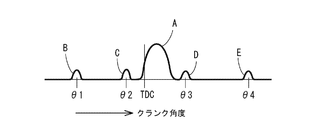
- the common rail system 117 is configured to execute the main injection A near the top dead center (TDC).
- TDC top dead center
- the common rail system 117 executes a small amount of pilot injection B for the purpose of reducing NOx and noise at the time of the crank angle ⁇ 1 about 60 ° before the top dead center
- Pre-injection C is executed for the purpose of noise reduction immediately before the crank angle ⁇ 2
- particulate matter hereinafter referred to as PM
- the after-injection D and the post-injection E are executed for the purpose of promoting purification.
- a fuel supply pump 116 is connected to the fuel tank 118 via a fuel return pipe 129.
- a common rail return pipe 131 is connected to the end of the cylindrical common rail 120 in the longitudinal direction via a return pipe connector 130 that limits the pressure of fuel in the common rail 120. That is, surplus fuel from the fuel supply pump 116 and surplus fuel from the common rail 120 are collected in the fuel tank 118 via the fuel return pipe 129 and the common rail return pipe 131.
- An exhaust pipe 77 connected to the exhaust downstream side of the exhaust manifold 71 includes an exhaust throttle device 82 for adjusting the exhaust pressure of the engine 70 and a diesel particulate filter 50 (hereinafter referred to as DPF) which is an example of an exhaust gas purification device. Connected). Exhaust gas discharged from each cylinder to the exhaust manifold 71 is purified through the exhaust pipe 77, the exhaust throttle device 82, and the DPF 50, and then released to the outside.
- DPF diesel particulate filter 50
- the DPF 50 is for collecting PM and the like in the exhaust gas.
- the DPF 50 according to the embodiment is configured by accommodating a diesel oxidation catalyst 53 such as platinum and a soot filter 54 in series in a substantially cylindrical filter case 52 in a casing 51 made of a refractory metal material.
- the diesel oxidation catalyst 53 is disposed on the exhaust upstream side of the filter case 52, and the soot filter 54 is disposed on the exhaust downstream side.
- the soot filter 54 has a honeycomb structure having a large number of cells partitioned by porous (filterable) partition walls.
- an exhaust introduction port 55 communicating with the exhaust downstream side of the exhaust throttle device 82 in the exhaust pipe 76 is provided.
- One end of the casing 51 is closed by a first bottom plate 56, and one end of the filter case 52 facing the first bottom plate 56 is closed by a second bottom plate 57.
- the annular gap between the casing 51 and the filter case 52 and the gap between the bottom plates 56 and 57 are filled with a heat insulating material 58 such as glass wool so as to surround the diesel oxidation catalyst 53 and the soot filter 54.
- the other side of the casing 51 is closed by two lid plates 59 and 60, and a substantially cylindrical exhaust outlet 61 passes through both the lid plates 59 and 60.
- a resonance chamber 63 that communicates with the inside of the filter case 52 via a plurality of communication pipes 62 is provided between the lid plates 59 and 60.
- An exhaust gas introduction pipe 65 is inserted into an exhaust introduction port 55 formed on one side of the casing 51.
- the tip of the exhaust gas introduction pipe 65 projects across the casing 51 to the side surface opposite to the exhaust introduction port 55.
- a plurality of communication holes 66 opening toward the filter case 52 are formed on the outer peripheral surface of the exhaust gas introduction pipe 65.
- a portion of the exhaust gas introduction pipe 65 that protrudes from the side surface opposite to the exhaust introduction port 55 is closed by a lid 67 that is detachably screwed to the portion.
- the DPF 50 is provided with a DPF temperature sensor 26 that detects an exhaust gas temperature in the DPF 50 as an example of a detection unit.
- the DPF temperature sensor 26 of the embodiment is mounted through the casing 51 and the filter case 52, and the tip thereof is located between the diesel oxidation catalyst 53 and the soot filter 54.
- the DPF 50 is provided with a differential pressure sensor 68 for detecting the clogged state of the soot filter 54 as an example of a detecting means.
- the differential pressure sensor 68 of the embodiment detects a pressure difference (differential pressure) between the upstream and downstream sides of the soot filter 54 in the DPF 50.
- the upstream side exhaust pressure sensor 68 a constituting the differential pressure sensor 68 is attached to the lid 67 of the exhaust gas introduction pipe 65, and the downstream side exhaust pressure sensor 68 b is interposed between the soot filter 54 and the resonance chamber 63. It is installed. It is well known that there is a certain law between the pressure difference between the upstream and downstream of the DPF 50 and the amount of PM accumulated in the DPF 50.
- the PM accumulation amount in the DPF 50 is estimated from the pressure difference detected by the differential pressure sensor 68, and the intake throttle device 81 and the common rail 120 are operated based on the estimation result, thereby regenerating the soot filter 54.
- Control DPF regeneration control
- the clogged state of the soot filter 54 is not limited to the differential pressure sensor 68 but may be an exhaust pressure sensor that detects the pressure upstream of the soot filter 54 in the DPF 50.
- the exhaust pressure sensor is adopted, the pressure (reference pressure) on the upstream side of the soot filter 54 when PM is not deposited on the soot filter 54 is compared with the current pressure detected by the exhaust pressure sensor. As a result, the clogged state of the soot filter 54 is determined.
- the exhaust gas from the engine 5 enters the exhaust gas introduction pipe 65 via the exhaust introduction port 55 and is ejected into the filter case 52 from each communication hole 66 formed in the exhaust gas introduction pipe 65.
- the diesel oxidation catalyst 53 and the soot filter 54 are passed through in this order for purification.
- PM in the exhaust gas is collected without passing through the porous partition wall between the cells in the soot filter 54.
- exhaust gas that has passed through the diesel oxidation catalyst 53 and the soot filter 54 is discharged from the exhaust outlet 61.
- an ECU 11 is provided for operating a fuel injection valve 119 for each cylinder in the engine 70.
- the ECU 11 is a general-purpose reproduction program GPM that selectively executes any one of a plurality of reproduction modes (to be described later), a ROM 32 as a fixed storage unit that stores various data fixedly in advance, in addition to a CPU 31 that executes various arithmetic processes and controls.
- EEPROM 33 as a rewritable variable storage means for storing etc., RAM 34 for temporarily storing various data, timer 35 for time measurement, input / output interface, and the like, which are arranged in the engine 70 or in the vicinity thereof.
- At least the rail pressure sensor 12 that detects the fuel pressure in the common rail 120, the electromagnetic clutch 13 that rotates or stops the fuel pump 116, and the rotational speed of the engine 70 (camshaft position of the crankshaft 74) are detected.
- Regeneration switch 21 as a regeneration permission input means for selecting and operating, differential pressure sensor 68 (upstream exhaust pressure sensor 68a and downstream exhaust pressure sensor 68b), DPF temperature sensor 26 for detecting exhaust gas temperature in DPF 50, and DPF 50 regeneration operation
- the parking brake operation means 29 is an example of a travel system operation means for operating the travel system of the work machine.
- each fuel injection valve 119 for at least four cylinders is connected to the output side of the ECU 11. That is, the high-pressure fuel stored in the common rail 120 is injected from the fuel injection valve 119 in a plurality of times during one stroke while controlling the fuel injection pressure, the injection timing, the injection period, and the like, so that nitrogen oxide (NOx ), And complete combustion with reduced generation of soot, carbon dioxide (CO2), etc. is performed to improve fuel efficiency.
- NOx nitrogen oxide
- CO2 carbon dioxide
- an intake throttle device 81 for adjusting the intake pressure (intake amount) of the engine 70, an exhaust throttle device 82 for adjusting the exhaust pressure of the engine 70, and a failure notification of the ECU 11 are notified.
- a regeneration prohibition lamp 28 is connected as a regeneration prohibition notification means that operates during the prohibition operation. Data relating to blinking of each of the lamps 22 to 24 and 28 is stored in the EEPROM 33 of the ECU 11 in advance.
- the regeneration lamp 24 serves as a regeneration notice unit that operates when the clogged state of the DPF 50 exceeds a specified level, and also serves as a regeneration notification unit that informs that the DPF 50 regeneration operation is being performed. It constitutes a single indicator.
- the regeneration switch 21, the regeneration prohibiting button 27, and the lamps 22 to 24, 28 are provided on the instrument panel 40 in the working machine to be mounted with the engine 70.
- the regeneration switch 21 is an alternate operation type. That is, the playback switch 21 is a lock-type push switch that is locked at the pressed position when pressed once and returns to the original position when pressed again. If the reproduction switch 21 is pressed, the apparatus is configured to be able to shift to each reproduction mode described later.
- the reproduction prohibition button 27 is of a momentary operation type. That is, the regeneration prohibiting button 27 is a non-locking type push switch that generates one ON pulse signal when pressed once. While the operator is pressing the regeneration prohibiting button 27, the current driving state of the engine 70 is maintained and the execution of each regeneration mode is prohibited. While the operator presses the regeneration prohibiting button 27, the engine 70 is not forcedly driven and post-injected so that the exhaust gas temperature rises.
- the EEPROM 33 of the ECU 11 stores in advance an output characteristic map M (see FIG. 3) indicating the relationship between the rotational speed N of the engine 70 and the torque T (load).
- the EEPROM 33 also stores in advance a main program MPM (see FIG. 6) for DPF 50 regeneration control and a general-purpose reproduction program GPM (see FIG. 7) that selectively executes one of a plurality of regeneration modes. The flow of these programs MPM and GPM will be described later.
- the output characteristic map M is obtained through experiments.
- the rotational speed N is taken on the horizontal axis and the torque T is taken on the vertical axis.
- the output characteristic map M is a region surrounded by a solid line Tmx drawn upwardly.
- a solid line Tmx is a maximum torque line representing the maximum torque for each rotational speed N.
- the output characteristic maps M stored in the ECU 11 are all the same (common).
- the output characteristic map M is divided vertically by a boundary line BL representing the relationship between the rotational speed N and the torque T when the exhaust gas temperature is the regeneration boundary temperature (about 300 ° C.). .
- the upper region across the boundary line BL is a reproducible region in which PM deposited on the soot filter 54 can be oxidized and removed (the oxidizing action of the oxidation catalyst 53 works), and the lower region is not oxidized and removed of PM. This is a non-reproducible region that accumulates on the soot filter 54.
- the ECU 11 basically calculates the torque T based on the output characteristic map M, the rotational speed N detected by the engine speed sensor 14, and the throttle position detected by the throttle position sensor 16 and performs target fuel injection.
- the fuel injection control for obtaining the amount and operating the common rail system 117 based on the calculation result is executed.
- the fuel injection amount is adjusted by adjusting the valve opening period of each fuel injection valve 119 and changing the injection period to each injector 115.
- a flag table FT corresponding to each regeneration mode related to the DPF 50 regeneration control is stored in advance. As shown in FIGS. 18A to 18C, the flag table FT exists for each type of reproduction mode, and plays a role as an identification factor of the reproduction mode.
- an external tool such as a ROM writer, which is connected to the ECU 11 via a communication terminal line, has one type of flag table FT corresponding to the type of playback mode, that is, a working machine to be mounted with an engine. 39 is written before engine shipment (engine production).
- the ROM 32 stores a self-regeneration flag table FT1 (see FIG. 18A) corresponding to the self-regeneration mode.
- the ROM 32 stores an automatic auxiliary reproduction flag table FT2 (see FIG. 18B) corresponding to the automatic auxiliary reproduction mode.
- the ROM 32 stores a manual auxiliary regeneration flag table FT3 (see FIG. 18C) corresponding to the manual auxiliary regeneration mode.
- flag table When the flag table is expressed by type as described above, a number is added to the reference symbol FT to indicate the relationship with the corresponding playback mode, and the flag table can be expressed together or an arbitrary flag table can be expressed. When expressing, “FT” with numbers removed is used.
- flag table FT stored in the ROM 32 is written to the EEPROM 33 when the ROM 32 and the EEPROM 33 are accessed for the first time, that is, when the work machine is first turned on and the ROM 32 and the EEPROM 33 are electrically connected. (Copied).
- the writing process is performed when the ECU 11 executes the main program MPM (see FIG. 6).
- the ECU 11 selects a playback mode based on the flag table FT written on the EEPROM 33 side, and executes the general-purpose playback program GPM in the selected playback mode (see FIG. 7).
- the control mode (regeneration mode) of the engine 70 includes a self-regeneration mode in which the engine 70 is driven under a condition in which the DPF 50 can be regenerated, and an automatic operation that automatically increases the exhaust gas temperature when the clogged state of the DPF 50 exceeds a specified level.
- the auxiliary regeneration mode, the forced regeneration mode in which fuel is supplied into the DPF 50 by the post-injection E also referred to as an initialization regeneration mode
- the fuel is supplied into the DPF 50 by the post-injection E
- the self-regeneration mode is mainly used in a working machine such as an engine generator that drives the engine 70 at a substantially constant rotational speed N and torque T.
- a working machine such as a combiner, a tractor, or a hydraulic excavator executes a normal operation mode for running on the road or performing various operations.
- the normal operation mode is a kind of self-regeneration mode.
- the automatic auxiliary regeneration mode is mainly used in general work machines such as a combiner and a tractor.
- the manual auxiliary regeneration mode is mainly used in a working machine such as a hydraulic excavator that performs precise work by relying on engine sound.
- “reproducible conditions” in the self-regeneration mode means that the relationship between the rotational speed N and the torque T in the engine 70 is a reproducible region of the output characteristic map M (an upper region across the boundary line BL). In other words, the exhaust gas temperature of the engine 70 is so high that the PM oxidation amount in the DPF 50 exceeds the PM trapping amount.
- the intake air amount and the exhaust air amount are limited by closing at least one of the intake throttle device 81 and the exhaust throttle device 82 to a predetermined opening based on the detection information of the differential pressure sensor 68. Then, since the engine 70 load increases, the engine 70 output increases in conjunction with this, and the exhaust gas temperature from the engine 70 increases. As a result, PM in the DPF 50 (soot filter 54) can be burned and removed.
- the forced regeneration (initialization regeneration) mode even when the automatic or manual auxiliary regeneration mode is executed, the clogged state of the DPF 50 is not improved (PM remains), or the accumulated drive time Te of the engine 70 is set to a set time T0 (for example, This is executed when it exceeds approximately 100 hours).
- the forced regeneration mode fuel is supplied into the DPF 50 by post-injection E, and the fuel is combusted by the diesel oxidation catalyst 53, thereby increasing the exhaust gas temperature in the DPF 50 (about 560 ° C.). As a result, the PM in the DPF 50 (soot filter 54) can be forcibly burned and removed.
- the emergency regeneration mode is executed when the clogged state of the DPF 50 is not improved even when the forced regeneration mode is executed.
- the exhaust from the engine 70 is maintained by maintaining the engine rotational speed N at a high idle rotational speed (maximum rotational speed) in addition to the control mode of the forced regeneration mode (execution of post-injection E).
- the exhaust gas temperature is raised by post-injection E even in the DPF 50 (about 600 ° C.).
- PM in the DPF 50 sin filter 54
- PM in the DPF 50 can be forcibly burned and removed under even better conditions than the forced regeneration mode.
- the upper limit value of the engine 70 output (rotational speed N and torque T) and the drivable time of the engine 70 are limited to keep the engine 70 in the minimum necessary driving state.
- the work machine can be escaped from the work place or moved to a store / service center. That is, the minimum necessary traveling function can be secured in the work machine.
- the engine 70, the intake throttle device 81, the exhaust throttle device 82, the common rail system 117, and the like are members involved in the DPF 50 regeneration operation.
- These 70, 81, 82, and 117 constitute a regeneration device for burning and removing PM in the DPF 50.
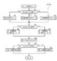
- the general-purpose playback program GPM is called, a playback mode is selected based on the flag table FT written on the EEPROM 33 side, and loop processing (DPF playback control) based on the general-purpose playback program GPM is performed in the selected playback mode.
- Execute S3.
- an update process for rewriting data (flag table FT, general-purpose reproduction program GPM, etc.) stored in the EEPROM 33 is executed using the external tool 39 (S4). ).
- the DPF regeneration control can be easily executed in a regeneration mode different from the initial setting by rewriting the flag table FT stored in the EEPROM 33 later.
- the algorithm shown in the flowcharts of FIGS. 7, 8, 12 and 14 is stored in the EEPROM 33 as a general-purpose reproduction program GPM.
- the flowchart of the self-regeneration mode in FIG. 8, the flowchart of the automatic emergency regeneration mode in FIG. 12, and the flowchart of the failure diagnosis process in FIGS. 16 (a) and 16 (b) are all subroutines of the general-purpose regeneration program GPM.
- the general-purpose reproduction program GPM is read from the EEPROM 33 to the RAM 34 and executed by the CPU 31. Note that although the subroutine (see FIGS. 8 to 16) changes depending on the playback mode, the general-purpose playback program GPM is also used in the second and third embodiments described later.
- the value of the mode selection flag RGMOD in the self-regeneration flag table FT1 read from the EEPROM 33 is determined (S11).
- a self-regeneration mode subroutine shown in FIG. 8 is called to execute self-regeneration processing (S12).
- the self-regeneration mode subroutine it is determined whether or not the DPF 50 is in “reproducible conditions” (S201). If it is in “reproducible conditions” (S201: YES), the regeneration on the instrument panel 40 is performed. The lamp 24 is turned on (S202) to inform the operator that the self-regeneration of the DPF 50 is smooth.
- the exhaust gas temperature of the engine 70 is high to the extent that the PM oxidation amount in the DPF 50 exceeds the PM collection amount.
- the automatic emergency regeneration mode subroutine shown in FIG. 12 first, it is determined whether or not the PM accumulation amount in the DPF 50 estimated from the detection result from the differential pressure sensor 68 is greater than or equal to a limit amount (limit level) (S601). In the self-regeneration mode, there is little risk of PM overdeposition, and basically less than the limit amount (S601: NO), so the substantial automatic emergency regeneration process is not performed and the process returns to the main routine of the loop process. Details of the flow of the automatic emergency regeneration mode will be described later in a second embodiment.
- the subroutine shown in FIG. 14 is called to move to the limp home process (S17).
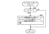
- the limp home mode subroutine shown in FIG. 14 it is first determined whether or not the limp home flag LF is set (S801).
- LF Since it is “0” (S801: NO), the substantial limp home process is not performed, and the process returns to the main routine of the loop process.
- the details of the flow of the limp home mode will be described in detail in the second embodiment, as in the automatic emergency regeneration mode.
- the value of the mode selection flag RGMOD is determined again (S19).
- RGMOD “0”
- the work equipment of the type that executes the self-regeneration mode omits the engine auxiliary equipment that is used for regeneration of the DPF 50, that is, the intake and exhaust throttle devices 81 and 82, it is a target of failure diagnosis. The device does not exist. Therefore, as shown in the flowchart of FIG. 16A, the first failure diagnosis process ends without doing anything, and the process returns to the main routine of the loop process to complete.
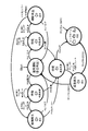
- Second Example of Loop Process a loop process of DPF regeneration control by the ECU 11 will be described with reference to the flowcharts of FIGS. 7, 9, 11, 12, 14, and 16, and the transition diagram of FIG.
- the second embodiment will be described.
- 2nd Example has shown the case where the engine 70 is mounted in the working machine (for example, combine etc.) of the type which performs automatic auxiliary
- the exhaust gas purification system of the second embodiment includes intake and exhaust throttle devices 81 and 82.
- the regeneration switch 21 for selecting whether or not to execute the regeneration mode at the operator's intention is omitted.
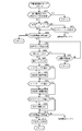
- the cumulative drive time Te of the engine 70 is equal to or longer than the set time T0 (S302).
- the set time T0 of the embodiment is set to about 100 hours, for example.
- the set time T0 may be several tens of hours or more.
- the accumulated drive time Te of the engine 70 is measured using the time information of the timer 35 in the ECU 11 while the engine 70 is being driven, and is stored and accumulated in the EEPROM 33.
- the value of the post injection flag APSTINJ in the automatic auxiliary regeneration flag table FT2 is determined (S303).
- post-injection is fuel injection performed after main injection in order to send high-pressure fuel to the exhaust path. Since the high-pressure fuel sent to the exhaust path mainly burns PM in the DPF 50, the DPF 50 can be regenerated.
- the routine proceeds to a subroutine for forced regeneration (initialization regeneration) mode shown in FIG. 11 (details will be described later).
- the cumulative drive time Te is less than the set time T0 (S302: NO)
- the prescribed amount in the embodiment is set to 8 g / l, for example. If the PM accumulation amount is less than the specified amount (S304: NO), the process returns to the main routine of the loop process. If the PM accumulation amount is equal to or greater than the specified amount (S304: YES), the measurement based on the time information of the timer 35 is started and the regeneration lamp 24 is blinked at a low speed (S305), and the DPF 50 regeneration operation (automatic auxiliary regeneration mode) is Notice the execution. In this case, the blinking frequency of the regeneration lamp 24 is set to 1 Hz, for example.
- the regeneration prohibiting button 27 is being pressed (prohibited) (S306). If it is being pressed (S306: ON), the regeneration prohibiting lamp 28 is turned on (S307). While the regeneration prohibiting button 27 is being pressed, the control mode of the engine 70 remains in the normal operation mode even though the PM accumulation amount is not less than the specified amount, and the current driving state of the engine 70 is maintained. Will be. That is, the transition to the automatic auxiliary regeneration mode (which may be referred to as the DPF 50 regeneration operation or the operation of the regeneration device) is prohibited. In addition, while the regeneration prohibition button 27 is being pressed, the regeneration prohibition lamp 28 is lit to appeal to the operator's vision that the regeneration operation of the DPF 50 is prohibited. I am letting.
- a predetermined leaving time for example, 30 minutes
- the process returns to the main routine of the loop process to shift to the emergency regeneration mode of the next process. If the leaving time has not elapsed (S308: NO), the process returns to step S305.
- step S306 if the regeneration prohibit button 27 is not being pressed (S306: OFF), it is determined whether or not a predetermined time (for example, 10 seconds) has elapsed since the regeneration lamp 24 started to flash slowly (S309). If the predetermined time has not elapsed (S309: NO), the process returns to step S305. When the predetermined time has elapsed (S309: YES), the regeneration prohibiting lamp 28 is turned off and the regeneration lamp 24 blinking at a low speed is turned on (S310), and then the automatic auxiliary regeneration processing from step S311 is executed.
- a predetermined time for example, 10 seconds
- step S311 the value of the intake throttle flag INTSLT in the automatic auxiliary regeneration flag table FT2 read from the EEPROM 33 is determined.
- the value of the exhaust throttle flag OUTSLT is determined (S313).
- the value of the post injection flag APSTINJ is determined (S315).
- post injection is executed by the common rail 120 (S316).
- the engine load is increased by limiting the intake air amount and the exhaust gas amount to raise the temperature of the exhaust gas, or the PM in the DPF 50 is directly combusted by post injection.
- the PM in the DPF 50 is removed, and the PM collection capability of the DPF 50 (the soot filter 54) is restored.
- an allowable amount (allowable level) (S317).
- the allowable amount of the embodiment is set to 4 g / l, for example. If the PM accumulation amount is less than the allowable amount (S317: YES), the regeneration lamp 24 is turned off to notify the end of the automatic auxiliary regeneration mode (S318), and the process returns to the main routine of the loop process. When the PM accumulation amount exceeds the allowable amount (S318: NO), PM is not sufficiently removed (the clogging state is not improved) even though the automatic auxiliary regeneration mode is executed. Therefore, the process proceeds to a forced regeneration (initialization regeneration) mode subroutine shown in FIG. 11 (details will be described later).
- the forced regeneration (initialization regeneration) mode subroutine shown in FIG. 11 measurement based on the time information of the timer 35 is started and the regeneration lamp 24 is blinked at a low speed (S501), and the operator performs the DPF 50 regeneration operation (forced regeneration mode). Notice the execution.
- the blinking frequency of the reproduction lamp 24 is set to 1 Hz, for example, as in the automatic auxiliary reproduction mode.
- a predetermined leaving time for example, 30 minutes
- the process returns to the main routine of the loop process to shift to the emergency regeneration mode of the next process. If the leaving time has not elapsed (S504: NO), the process returns to step S501.
- step S502 if the regeneration prohibit button 27 is not being pressed (S502: OFF), it is determined whether or not a predetermined time (for example, 10 seconds) has elapsed since the regeneration lamp 24 started to flash slowly (S505). If the predetermined time has not elapsed (S505: NO), the process returns to step S501. When the predetermined time has elapsed (S505: YES), the regeneration prohibiting lamp 28 is turned off and the regeneration lamp 24, which has been blinking at a low speed, is turned on (S506), and then the forced regeneration (initialization regeneration) processing after step S507 is performed. Execute.
- a predetermined time for example, 10 seconds
- the forced regeneration mode As described above, high-pressure fuel is supplied into the DPF 50 by the post injection E of the common rail system 117 (S507), and the high-pressure fuel is burned by the diesel oxidation catalyst 53, whereby the exhaust gas temperature in the DPF 50 To raise. As a result, the PM in the DPF 50 is forcibly burned and removed, and the PM collection capability of the DPF 50 is restored.
- the forced regeneration mode of the embodiment is executed for about 30 minutes, for example, and the common rail system 117 does not perform the post injection E after the lapse of the time.
- the cumulative drive time Te of the engine 70 is once reset and newly measured using the timer 35.
- the regeneration lamp 24 is turned off to notify the end of the forced regeneration mode (S509), and the process returns to the main routine of the loop process.
- the PM accumulation amount exceeds the allowable amount (S508: NO)
- the PM is not sufficiently removed even in the forced regeneration mode (the clogging state is not improved), and the process proceeds to the emergency regeneration mode of the next process. Therefore, the process returns to the main routine of the loop process.
- the automatic emergency regeneration mode subroutine first, it is determined whether or not the PM accumulation amount estimated from the detection result of the differential pressure sensor 68 is not less than a limit amount (limit level) (S601).
- the limit amount is set to a value exceeding the above-mentioned prescribed amount (see S304).
- the PM deposition amount equal to or greater than the limit amount means a state in which the DPF 50 is over-deposited PM and there is a possibility of PM runaway combustion. If the PM accumulation amount is less than the limit amount (S601: NO), the process returns to the main routine of the loop process.
- the regeneration lamp 24 blinks at high speed (S602), and the operator is notified of the execution of the DPF 50 regeneration operation (automatic emergency regeneration mode).
- the blinking frequency of the regeneration lamp 24 is set to a frequency different from that in the automatic auxiliary regeneration mode and the forced regeneration mode.
- the blinking frequency of the regeneration lamp 24 for automatic emergency regeneration mode notification is set to 2 Hz. That is, the regeneration lamp 24 operates in a warning mode (high-speed flashing) different from the operation mode (slow flashing) that prompts execution of the forced regeneration (initialization playback) mode.
- step S605 When a predetermined time (for example, 10 seconds) elapses from the start of fast blinking of the regeneration lamp 24 (S603: YES), the regeneration lamp 24 blinking at high speed is turned on (S604), and then automatic emergency regeneration processing from step S605 is executed. To do.
- high pressure fuel is supplied into the DPF 50 by the post injection E of the common rail system 117, and the high pressure fuel is burned by the diesel oxidation catalyst 53.
- the state of fuel injection to each cylinder is adjusted by electronic control of the common rail system 117, and the engine rotation speed N is maintained at a high idle rotation speed (maximum rotation speed).
- the exhaust gas temperature from the engine 70 is raised, the exhaust gas temperature is raised by the post injection E in the DPF 50 (about 600 ° C.).
- the PM in the DPF 50 can be forcibly burned and removed under better conditions than the reset regeneration mode, and the PM trapping ability of the DPF 50 can be recovered.
- step S611 the fuel injection state (injection pressure, injection timing, injection period, etc.) to each cylinder is adjusted by electronic control of the common rail system 117, and the rotational speed N in the idling state of the engine 70 is set to a low value. You may comprise so that it may maintain higher than an idle rotational speed (predetermined low rotational speed). With this configuration, since the exhaust gas temperature can be easily maintained at a high temperature, the number of executions of the DPF 50 regeneration operation can be reduced and the execution time can be shortened, so that the efficiency of the DPF 50 regeneration can be improved and the deterioration of fuel consumption can be suppressed. Also contributes.
- the efficiency of regeneration of the DPF 50 can be further promoted.
- rotation speed setting means such as a dial type is provided on the instrument panel so that the maintenance rotation speed can be changed according to the operation position of the rotation speed setting means.
- the automatic emergency regeneration mode of the embodiment is executed, for example, for about 15 minutes, and after the lapse of time (S612: YES), the common rail system 117 does not perform the post injection E and adjusts the fuel injection state to each cylinder. Then, the rotational speed N of the engine 70 is returned to the original rotational speed before the high idle fixing.
- step S612 After the elapse of the predetermined time in step S612, it is determined whether or not the exhaust gas temperature TP in the DPF 50 detected by the DPF temperature sensor 26 is equal to or lower than the lower limit temperature TP0 (S613). If the exhaust gas temperature TP in the DPF 50 exceeds the lower limit temperature TP0 (S613: YES), the process proceeds to step S615, the regeneration lamp 24 is turned off, the end of the automatic emergency regeneration mode is notified, and the main routine of the loop processing Return to.
- the PM over-deposition does not improve the clogged state of the DPF 50 because the exhaust gas temperature does not rise even though the automatic emergency regeneration mode is executed. Is in a state.
- the process After execution of the automatic emergency playback mode, the process returns to the main routine of the loop process shown in FIG. 7, and the limp home mode subroutine shown in FIG. 14 is called to execute the limp home process (S18).
- the limp home mode subroutine it is determined whether or not the limp home flag LF is set (S801). If the limp home flag LF is in a reset state (S801: NO), the process returns to the main routine of the loop process.
- the limp home flag LF corresponds to the fact whether or not the limp home mode has been executed in the past, and an external tool (for example, at a store) connected to the ECU 11 via a communication terminal line. Unless used, it will not be reset. Therefore, once the limp home mode is executed, it is impossible to return to another mode unless the limp home flag LF is reset at a dealer / service center.
- the process After passing through the limp home mode, the process returns to the main routine of the loop process shown in FIG. 7 to determine the value of the mode selection flag RGMOD (S19).
- the value of the intake throttle flag INTSLT is determined (S1001).
- the expansion devices 81 and 82 may be opened and closed, and it may be confirmed from the detection result whether or not the operation state is normal. Thereafter, the process returns to the main routine of the loop process and is completed.
- the third embodiment shows a case where the engine 70 is mounted on a working machine (for example, a hydraulic excavator) of a type that executes the manual auxiliary regeneration mode.
- a working machine for example, a hydraulic excavator
- regeneration of the DPF 50 is permitted by turning on the regeneration switch 21. Therefore, the engine device of the third embodiment includes not only the intake and exhaust throttle devices 81 and 82 but also the regeneration switch 21.
- step S405 it is determined whether or not the regeneration switch 217 is in an on state (S406). If the regeneration switch 217 is in an off state (S406: OFF), a predetermined leaving time (for example, 30 minutes) from the start of slow blinking of the regeneration lamp 24. It is determined whether or not elapses (S407). If the neglected time has elapsed (S407: YES), there is a concern about the possibility of PM over-deposition, so the process returns to the main routine of the loop process to shift to the emergency regeneration mode of the next process. If the leaving time has not elapsed (S407: NO), the process returns to step S405.
- step S406 If the regeneration switch 21 is on in step S406, the regeneration lamp 24 blinking at a low speed is turned on (S408), and then manual auxiliary regeneration processing from step S409 is executed. Since the flow of steps S409 to S416 is the same as the flow of steps S311 to S319 in the automatic auxiliary reproduction mode described in the second embodiment, detailed description thereof will be omitted.
- step S701 and S702 the flow of steps S701 and S702 is the same as the flow of steps S601 and S602 in the automatic emergency regeneration mode described in the second embodiment.
- step S702 it is determined whether or not both the regeneration switch 21 and the parking brake operation means 29 are on (S703, S705). This is intended to prohibit the transition to the manual emergency regeneration mode in the manual emergency regeneration mode unless the operator intentionally stops the running of the work equipment and various operations in order to greatly increase the engine speed N. Is.
- step S704 If one or both of the regeneration switch 21 and the parking brake operation means 29 are in an off state (S703: OFF, S705: OFF), has a predetermined leaving time (for example, 30 minutes) elapsed since the start of the rapid blinking of the regeneration lamp 24? It is determined whether or not (S704). If the neglected time has elapsed (S704: YES), there is a concern about the possibility of PM over-deposition, so the process returns to the main routine of the loop process to shift to the limp home mode of the next process. If the leaving time has not elapsed (S704: NO), the process returns to step S702.
- a predetermined leaving time for example, 30 minutes
- both the regeneration switch 21 and the parking brake operation means 29 are in the on state (S703: YES, S705: YES), the regeneration lamp 24 blinking at high speed is turned on (S706), and then the manual operation from step S707 is performed. Perform emergency regeneration processing.
- the flow of steps S707 to S717 is the same as the flow of steps S605 to S615 in the automatic emergency regeneration mode described in the second embodiment. Note that it is possible to determine the on / off state of only the regeneration switch 21 or to determine the on / off state of only the parking brake operation means 29. However, when both the regeneration switch 21 and the parking brake operation means 29 are provided, a higher effect can be exhibited as an interlock structure (a malfunction prevention structure) for executing the manual emergency regeneration mode. Even after the manual emergency regeneration mode is executed, the limp home process and the second failure diagnosis process are executed in the same manner as in the second embodiment.
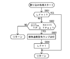
- the ECU 11 of the embodiment is configured to execute the interrupt process shown in FIG. 15 during the execution of the DPF 50 regeneration control.
- the interruption process is to check the detection result of the DPF temperature sensor 26 at appropriate time intervals.
- it is determined whether or not the limp home flag LF is set (S31). If the limp home flag LF is set (S901: YES), the limp home mode is still set. Since it is not possible to return to another mode from, return to the main routine of the loop processing and execute the limp home mode.
- the limp home flag LF is in the reset state (S901: NO)
- the exhaust temperature warning lamp 23 is turned on (S903), and then the limp home flag LF is set (S904).
- the process returns to the main routine of the loop process to execute the limp home mode.
- the abnormal temperature TPex of the embodiment is set to about 800 ° C., for example.
- the state in which the exhaust gas temperature TP in the DPF 50 exceeds the abnormal temperature TPex is understood to be that the over-deposited PM has runaway and burned. In this case, the DPF 50 is damaged (melted) or excessive emissions (air pollutants). May be discharged. Therefore, the limp home mode is promptly shifted.
- the exhaust gas purification device 50 disposed in the exhaust path 77 of the engine 70 and the ECU 11 that controls the driving of the engine 70 are provided.
- the flag table FT is fixedly stored in advance.
- the fixed storage unit 32 includes the fixed storage unit 32, the variable storage unit 33, and the like. Since the flag table FT stored in the fixed storage means 32 is written in the variable storage means 33 at the time of the first access, the flag table FT stored in the variable storage means 33 is rewritten later, DPF regeneration control can be easily executed in a regeneration mode different from the initial setting. Accordingly, when it is desired to change the reproduction mode, it is not necessary to delete the flag table FT one by one, for example, by replacing the fixed storage means 32, or to rewrite the general-purpose reproduction program GPM. There is an effect that it is easy to deal with. For example, it is easy for the customer to correct the setting suitable for the company's specifications despite the engine 70 purchased from the outside.
- the exhaust gas purification device 50 disposed in the exhaust path 77 of the engine 70 and the regeneration for removing the particulate matter in the exhaust gas purification device 50 by combustion.
- the devices 70, 81, 82, 117, the regeneration notice means 24 that operates when the clogged state of the exhaust gas purifying device 50 exceeds a specified level, and the fact that the regeneration devices 70, 81, 82, 117 are in operation.
- a playback notification means 24 for notifying, and the playback notification means 24 is operated before the playback devices 70, 81, 82, 117 are operated.
- the operator can assume in advance the impact of the torque T variation and the change in the engine 70 sound.
- the regeneration notification allows the operator to easily grasp the transition to the exhaust gas purification device 50 regeneration operation. Therefore, there is an effect that the operator feels uncomfortable due to the regeneration operation of the exhaust gas purification device 50. For example, the exhaust gas purification device 50 regeneration operation, which may hinder the precise work performed by the operator using the engine 70 sound, can be compensated.
- the reproduction notice unit 24 and the reproduction notification unit 24 are composed of a single display 24, and display the reproduction notice and the reproduction notice in different modes. Since it is comprised so that the said reproduction
- the exhaust gas purifying apparatus 50 is provided with a regeneration prohibiting input means 27 that prohibits the regeneration operation.
- the regeneration device 70, 81, 82, 117 is configured not to operate (the regeneration operation of the exhaust gas purification device 50 is prohibited).
- the regeneration operation of the exhaust gas purifying device 50 can be prohibited by the operator's intention according to the state of the work implement to be mounted. For this reason, while the regeneration control for recovering the particulate matter collecting ability of the exhaust gas purifying device 50 can be automatically executed, the operator can smoothly perform the precise work that is executed relying on the engine 70 sound. There is an effect. That is, it is possible to eliminate the drawbacks of the regeneration operation of the exhaust gas purifying device 50 that may hinder the precise operation.
- the reproduction prohibition notification means 28 that operates during the prohibition operation of the regeneration prohibition input means 27 is provided, the prohibition operation of the regeneration prohibition input means 27 is performed. During the time, the fact that the regeneration operation of the exhaust gas purifying device 50 is prohibited can be appealed to the operator's vision by the notification of the regeneration prohibition notifying means 28, and the operator's attention can be surely called. There is also an advantage that by confirming the state of the reproduction prohibition notification means 28, it can be easily confirmed whether or not reproduction is prohibited.
- the exhaust gas purifying device 50 disposed in the exhaust path 77 of the common rail engine 70 and the particulate matter in the exhaust gas purifying device 50 are burned and removed. Even if a forced regeneration (initialization regeneration) mode in which fuel is supplied into the exhaust gas purification device 50 by post-injection E is executed, the exhaust gas is provided. When the clogging state of the purifying device 50 does not improve, an emergency that supplies fuel into the exhaust gas purifying device 50 by post injection E and maintains the rotational speed N of the engine 70 at a predetermined value (high idle rotational speed).
- the regeneration notice means 24 that operates when the clogged state of the exhaust gas purifying device 50 exceeds a specified level, and the operations of the regeneration devices 70, 81, 82, and 117. If the clogged state of the exhaust gas purifying device 50 is not improved even after executing the reset regeneration mode, the regeneration notifying means 24 is operated to activate the regeneration notice. Since the emergency regeneration mode is executed if the permission operation of the regeneration permission input means 21 is performed under the operation of the means 24, the emergency regeneration mode is not executed unless the operator intends to do so. become. For this reason, in the emergency regeneration mode in which the engine rotation speed N is significantly increased, the operator can assume in advance the impact of torque T fluctuation and the change in the engine 70 sound. Therefore, for example, it is possible to avoid an unexpected situation in which the working machine to be mounted with the engine accelerates rapidly.
- parking brake operating means 29 is provided for maintaining the work machine equipped with the engine 70 in a braking state, and braking operation of the parking brake operating means 29 is performed. If not, the emergency regeneration mode is not executed regardless of the clogged state of the exhaust gas purifying device 50 and the operation state of the regeneration permission input means 21. Unless the traveling of the work machine and various operations are stopped, the transition to the emergency regeneration mode can be prohibited. For this reason, in the emergency regeneration mode in which the rotational speed N of the engine 70 is significantly increased, it is possible to reliably avoid the occurrence of an unexpected situation in which, for example, the working machine is accelerated rapidly. That is, a higher effect can be exhibited as an interlock structure (malfunction prevention structure) for execution of the emergency regeneration mode.
- the exhaust gas purification device 50 disposed in the exhaust path 77 of the engine 70 is provided, and the exhaust gas temperature TP in the exhaust gas purification device 50 is an abnormal temperature.
- the upper limit thresholds Nlt and Tlt of the rotational speed N and torque T of the engine 70 and the limp home mode for limiting the driveable time Tilt of the engine 70 are executed.
- the engine 70 is held in the minimum necessary driving state by executing the limp home mode. That is, the minimum necessary traveling function can be ensured for the work machine equipped with the engine. Therefore, while preventing the exhaust gas purifying device 50 from being damaged (melted) and excessively discharged, the working machine can be removed from the work place or moved to a store / service center, for example. It is possible to evacuate to a safe place.
- the exhaust gas purification device 50 is highly likely to be damaged, but must be inspected and maintained by, for example, a store / service center. For this reason, there is an advantage that the possibility of using the exhaust gas purification device 50 in a damaged state can be avoided and excessive emission emission can be prevented.
- the exhaust gas temperature TP in the exhaust gas purification device 50 is provided with the abnormally high temperature notification means 23 that operates when the exhaust gas temperature TP is equal to or higher than the abnormal temperature TPex.
- the notification of the abnormally high temperature notification means 28 can notify the operator of an abnormal exhaust gas temperature (runaway combustion), which helps to prevent the expansion of damage such as melting of the exhaust gas purification device 50.
- the exhaust gas purification device 50 disposed in the exhaust path 77 of the common rail engine 70 and the intake throttle disposed in the intake and exhaust systems 76 and 77 of the engine 70.
- At least one of the device 81 and the exhaust throttle device 82 and operates when at least one of the intake throttle device 81 and the exhaust throttle device 82 is activated when the clogged state of the exhaust gas purification device 50 exceeds a specified level.
- the auxiliary regeneration mode for increasing the temperature of the exhaust gas from the engine 70 is executed by this, while the clogged state of the exhaust gas purifying device 50 is not improved even when the auxiliary regeneration mode is executed, the post-injection E is performed.
- the forced regeneration (initialization regeneration) mode for supplying the fuel into the exhaust gas purification device 50 is executed.
- the intake air amount and the exhaust gas amount are limited by using at least one of the intake air throttle device 81 and the exhaust air throttle device 82.
- the output of the engine 70 is increased and the exhaust gas temperature from the engine 70 is raised. If the clogged state of the exhaust gas purifying device 50 is not improved even after the auxiliary regeneration mode is executed, fuel is supplied into the exhaust gas purifying device 50 by post injection E and burned, whereby the exhaust gas is purified.
- the exhaust gas temperature in the gas purification device 50 is raised.
- the exhaust gas temperature in the exhaust gas purification device 50 is locally increased in the forced regeneration mode.
- the particulate matter in the exhaust gas purification device 50 can be forcibly and efficiently burned and removed.
- the auxiliary regeneration mode is executed when the exhaust gas purification device 50 is clogged under normal operating conditions, the frequency of execution of the forced regeneration mode, that is, the frequency of execution of post injection E can be reduced. . For this reason, it is possible to suppress deterioration in fuel consumption and to suppress deterioration in durability of the engine 70 caused by engine oil dilution.
- the exhaust gas purifying device 50 if the cumulative drive time Te of the engine 70 is equal to or longer than a preset set time T0, the exhaust gas purifying device 50 is not clogged regardless of the clogged state. Since it is configured to shift to the forced regeneration mode, the execution frequency of the forced regeneration mode, that is, the execution frequency of the post injection E can be lowered. For this reason, it is possible to suppress deterioration in fuel consumption and to suppress deterioration in durability of the engine 70 caused by engine oil dilution.
- the accumulated amount (estimated amount) of the accumulated amount is deviated by executing the forced regeneration mode. Since it can be reset every set time T0, there is also an advantage that the reliability of the control relating to the regeneration of the exhaust gas purifying device 50 can be ensured.
- the cumulative drive time Te of the engine 70 is reset and then a new measurement is started. For example, it is not necessary for the operator to perform the reset operation of the cumulative drive time Te, and there is an effect that the forced regeneration mode can be smoothly executed at each set time T0 without the operator's trouble.
- the exhaust gas purifying device 50 disposed in the exhaust path 77 of the common rail engine 70 is provided, and the particulate matter deposited in the exhaust gas purifying device 50 is provided.
- the exhaust gas purification system is configured to be able to execute a plurality of regeneration modes for burning and removing the engine 70, and as one of the plurality of regeneration modes, a cumulative driving time Te of the engine 70 is set to a preset time T0.
- an initialization regeneration (forced regeneration) mode which supplies fuel in the exhaust gas purification device 50 by post injection E irrespective of the clogged state of the exhaust gas purification device 50, the above-mentioned
- an initialization regeneration (forced regeneration) mode is executed without the operator having to perform setting operations one by one, and the exhaust gas purification is performed.
- the particulate matter in the device 50 can be forcibly and efficiently burn and remove. That is, the execution frequency of the forced regeneration mode, in other words, the execution frequency of the post injection E can be lowered. Therefore, while the exhaust gas purifying device 50 can be efficiently initialized and regenerated, it is possible to suppress deterioration in fuel consumption and to suppress deterioration in durability of the engine 70 due to engine oil dilution.
- reproduction notice means 24 for calling attention for urging execution of each reproduction mode, and reproduction permission input means 21 for permitting execution of each reproduction mode, And when the regeneration permission input means 21 is in a non-operating state under the operation of the regeneration notice means 24, the initialization regeneration mode is not executed.
- the initialization regeneration mode that is, the regeneration operation of the exhaust gas purification device 50 can be prohibited by the operator's intention according to the state of the engine. For this reason, the initialization reproduction mode is not executed in a state that the operator does not expect at all, and there is an effect that the operator can smoothly perform the detailed work that is performed by relying on the engine sound. That is, it is possible to eliminate the drawbacks of the regeneration operation of the exhaust gas purifying device 50 that may hinder the precise operation.
- the reproduction notice means 24 is in the initialization reproduction mode. Since the exhaust gas purification device 50 is configured to operate in a warning mode different from the operation mode that prompts the execution, the exhaust gas purification device 50 is left as it is for a long time in a state where regeneration is necessary, and the particulate form in the exhaust gas purification device 50 When there is a high possibility that the substance will increase to the state of over-deposition, it is possible to alert the operator with a warning mode different from the operation mode that prompts execution of the initialization regeneration mode, and particulate matter over-deposition (and thus runaway combustion) ) Can be prevented.
- the playback warning means in the warning mode after the power is restored. 24 see step S301 in FIG. 9 and step S401 in FIG. 10
- the exhaust gas purification device 50 can be used as it is without being fully regenerated. Can be avoided.
- the vehicle is provided with traveling system operation means 29 for operating the traveling system of the work machine equipped with the engine 70, and the regeneration notice means 24 is in the warning mode.
- the exhaust gas purifying device supplies fuel by post-injection by the permission operation of the regeneration permission input means 21 and the operation of the travel system operation means 29 corresponding to the travel stop state of the work implement. 50 and is configured to shift to an emergency regeneration mode in which the engine rotation speed N is maintained at a predetermined value (high idle rotation speed). Therefore, the operator intends to run the work machine and perform various operations. Unless it is stopped, the transition to the emergency reproduction mode can be prohibited. For this reason, in the emergency regeneration mode in which the engine rotation speed N is significantly increased, it is possible to reliably avoid an unexpected situation in which, for example, the work implement is accelerated rapidly.
- the traveling system operating means of the embodiment is the parking brake operating means 29 for maintaining the work implement in a braking state, but is not limited thereto.
- it may be a main transmission operating means such as a main transmission lever provided in the work implement, an auxiliary transmission operating means such as an auxiliary transmission switch, or a forward / reverse switching operation means such as a reverser lever.
- the neutral operation state of each operation means is an operation corresponding to the traveling stop state of the work implement.
- the present invention is not limited to the above-described embodiment, and can be embodied in various forms.
- the fuel injection device of the engine device is not limited to the common rail type, but may be an electronic governor type.
- the configuration of each unit is not limited to the illustrated embodiment, and various modifications can be made without departing from the spirit of the present invention.
Landscapes
- Engineering & Computer Science (AREA)
- Chemical & Material Sciences (AREA)
- Combustion & Propulsion (AREA)
- Mechanical Engineering (AREA)
- General Engineering & Computer Science (AREA)
- Chemical Kinetics & Catalysis (AREA)
- Health & Medical Sciences (AREA)
- Toxicology (AREA)
- Processes For Solid Components From Exhaust (AREA)
- Exhaust Gas After Treatment (AREA)
- Electrical Control Of Air Or Fuel Supplied To Internal-Combustion Engine (AREA)
- Exhaust Gas Treatment By Means Of Catalyst (AREA)
Abstract
Description
まず、図1及び図2を参照しながら、エンジン70及びその周辺の構造を説明する。図2に示すように、エンジン70は4気筒型のディーゼルエンジンであり、上面にシリンダヘッド72が締結されたシリンダブロック75を備えている。シリンダヘッド72の一側面には吸気マニホールド73が接続されており、他側面には排気マニホールド71が接続されている。シリンダブロック75の側面のうち吸気マニホールド73の下方には、エンジン70の各気筒に燃料を供給するコモンレールシステム117が設けられている。吸気マニホールド73の吸気上流側に接続された吸気管76には、エンジン70の吸気圧(吸気量)を調節するための吸気絞り装置81とエアクリーナ(図示省略)とが接続される。
次に、図1~図5を参照しながら、エンジン70の制御関連の構成を説明する。図1に示す如く、エンジン70における各気筒の燃料噴射バルブ119を作動させるECU11を備えている。ECU11は、各種演算処理や制御を実行するCPU31の他、各種データを予め固定的に記憶した固定記憶手段としてのROM32、後述する複数の再生モードのいずれかを選択的に実行する汎用再生プログラムGPM等を記憶する書換可能な可変記憶手段としてのEEPROM33、各種データを一時的に記憶させるRAM34、時間計測用のタイマ35、及び入出力インターフェイス等を有しており、エンジン70又はその近傍に配置される。
次に、図6のフローチャートを参照しながら、ECU11によるDPF再生制御のメイン処理の一例について説明する。図6のフローチャートにて示すアルゴリズムは、EEPROM33にメインプログラムMPMとして記憶されていて、RAM34に呼び出されてからCPU31にて実行される。この場合、作業機の電源投入によってメインプログラムMPMが起動し、ROM32とEEPROM33とのアクセスが初めてであれば(S1:YES)、ROM32に記憶された1種類のフラグテーブルFTを、EEPROM33側に書き込む(S2)。次いで、汎用再生プログラムGPMを呼び出して、EEPROM33側に書き込まれたフラグテーブルFTに基づき再生モードを選択し、当該選択された再生モードにて、汎用再生プログラムGPMに基づくループ処理(DPF再生制御)を実行する(S3)。その後、ECU11に外部ツール39が接続されていれば、外部ツール39を用いて、EEPROM33に記憶されているデータ(フラグテーブルFTや汎用再生プログラムGPM等)を書き換えたりする更新処理を実行する(S4)。
次に、図7、図8、図12及び図14のフローチャートを参照しながら、ECU11によるDPF再生制御のループ処理の第1実施例について説明する。第1実施例は、自己再生モードを実行するタイプの作業機(例えばエンジン発電機等)にエンジン70を搭載した場合を示している。この種の作業機では、ほぼ一定の回転速度N及びトルクTにてエンジン70を駆動させるから、DPF50内でのPM酸化量がPM捕集量を上回る程度に、エンジン70の排気ガス温度が高温になっている。かかる点を考慮して、第1実施例のエンジン装置では、吸気絞り装置81、排気絞り装置82、再生スイッチ21、再生禁止ボタン27及び再生禁止ランプ28等が省略される。
次に、図7、図9、図11、図12、図14及び図16のフローチャート、並びに、図18の遷移図を参照しながら、ECU11によるDPF再生制御のループ処理の第2実施例について説明する。第2実施例は、自動補助再生モードを実行するタイプの作業機(例えばコンバイン等)にエンジン70を搭載した場合を示している。自動補助再生モードでは、DPF50の詰まり程度が規定水準を超えた場合に自動的に排気ガスを昇温させるから、第2実施例の排気ガス浄化システムでは、吸気及び排気絞り装置81,82を備えるものの、再生モードを実行するか否かをオペレータの意思で選択する再生スイッチ21が省略される。
次に、図7、図10及び図13のフローチャート、並びに、図18の遷移図を参照しながら、ECU11によるDPF再生制御のループ処理の第3実施例を説明する。第3実施例は、手動補助再生モードを実行するタイプの作業機(例えば油圧ショベル等)にエンジン70を搭載した場合を示している。手動補助再生モードでは、再生スイッチ21の入り操作によってDPF50の再生を許可するから、第3実施例のエンジン装置では、吸気及び排気絞り装置81,82だけでなく、再生スイッチ21も備えている。
さて、実施形態のECU11は、DPF50再生制御の実行中に、図15に示す割り込み処理を実行するように構成されている。当該割り込み処理は、適宜時間間隔にてDPF温度センサ26の検出結果をチェックするというものである。この場合、図15のフローチャートに示すように、リンプホームフラグLFがセットされているか否かを判別し(S31)、リンプホームフラグLFがセット状態であれば(S901:YES)、未だにリンプホームモードから他のモードへ復帰できない状態なので、ループ処理のメインルーチンに戻り、リンプホームモードを実行する。
上記の記載並びに図1~図7及び図18から明らかなように、エンジン70の排気経路77に配置された排気ガス浄化装置50と、前記エンジン70の駆動を制御するECU11とを備えているエンジン装置であって、前記排気ガス浄化装置50に対する複数の再生モードのいずれかを選択的に実行する汎用再生プログラムGPMと、任意の再生モードに対応するフラグテーブルFTとを記憶する書換可能な可変記憶手段33を備えており、前記ECU11が前記フラグテーブルFTに基づき選択される再生モードにて前記汎用再生プログラムGPMを実行するから、1種類の前記汎用再生プログラムGPMにおいて前記フラグテーブルFTを変更するだけで、作業機の種類毎に異なる再生モードに対応可能となる。このため、多種多様な作業機に対して前記ECU11の共用化(共通仕様化)を図れるという効果を奏する。つまり、前記ECU11の汎用性向上というメリットと、前記ECU11の各再生モードに対する適合性確保というメリットとを両立できるという効果を奏する。
本願発明は、前述の実施形態に限らず、様々な態様に具体化できる。例えばエンジン装置の燃料噴射装置はコモンレール式のものに限らず、電子ガバナ式のものでもよい。その他、各部の構成は図示の実施形態に限定されるものではなく、本発明の趣旨を逸脱しない範囲で種々変更が可能である。
GPM 汎用再生プログラム
11 ECU
21 再生スイッチ(再生許可入力手段)
24 再生ランプ(再生予告手段兼再生報知手段)
31 CPU
32 ROM(固定記憶手段)
33 EEPROM(可変記憶手段)
50 DPF(排気ガス浄化装置)
70 エンジン
120 コモンレール
Claims (5)
- コモンレール式エンジンの排気経路に配置された排気ガス浄化装置を備えており、前記排気ガス浄化装置内に堆積した粒子状物質を燃焼除去する複数の再生モードを実行可能に構成されている排気ガス浄化システムであって、
前記複数の再生モードの1つとして、前記エンジンの累積駆動時間が予め設定された設定時間以上になると、前記排気ガス浄化装置の詰り状態に拘らず、ポスト噴射にて燃料を前記排気ガス浄化装置内に供給する初期化再生モードを有している、
排気ガス浄化システム。 - 前記各再生モードの実行を促すための注意を喚起させる再生予告手段と、前記各再生モードの実行を許可する再生許可入力手段とを備えており、
前記再生予告手段の作動下において前記再生許可入力手段が非操作状態である場合は前記初期化再生モードを実行しないように構成されている、
請求項1に記載した排気ガス浄化システム。 - 前記再生許可入力手段の非操作状態が所定の放置時間以上継続している場合は、前記再生予告手段が前記初期化再生モードの実行を促す作動態様と異なる警告態様にて作動するように構成されている、
請求項2に記載した排気ガス浄化システム。 - 前記再生予告手段の前記警告態様での作動中において電源が遮断されたときは、前記電源復帰後に前記警告態様にて前記再生予告手段の作動を再開させるように構成されている、
請求項3に記載した排気ガス浄化システム。 - 前記エンジンを搭載した作業機の走行系を操作する走行系操作手段を備えており、前記再生予告手段が前記警告態様にて作動した場合は、その後における前記再生許可入力手段の許可操作と、前記作業機の走行停止状態に対応する前記走行系操作手段の操作とによって、ポスト噴射にて燃料を前記排気ガス浄化装置内に供給し且つエンジン回転速度を所定値に維持する緊急再生モードに移行するように構成されている、
請求項3又は4に記載した排気ガス浄化システム。
Priority Applications (4)
| Application Number | Priority Date | Filing Date | Title |
|---|---|---|---|
| EP11789574.8A EP2578826B1 (en) | 2010-06-02 | 2011-04-28 | Exhaust gas purification system |
| US13/700,225 US9546586B2 (en) | 2010-06-02 | 2011-04-28 | Exhaust gas purification system |
| CN201180026847.1A CN102933802B (zh) | 2010-06-02 | 2011-04-28 | 排气气体净化系统 |
| KR1020127030719A KR101802242B1 (ko) | 2010-06-02 | 2011-04-28 | 배기가스 정화 시스템 |
Applications Claiming Priority (2)
| Application Number | Priority Date | Filing Date | Title |
|---|---|---|---|
| JP2010-126774 | 2010-06-02 | ||
| JP2010126774A JP5839784B2 (ja) | 2010-06-02 | 2010-06-02 | 排気ガス浄化システム |
Publications (1)
| Publication Number | Publication Date |
|---|---|
| WO2011152165A1 true WO2011152165A1 (ja) | 2011-12-08 |
Family
ID=45066547
Family Applications (1)
| Application Number | Title | Priority Date | Filing Date |
|---|---|---|---|
| PCT/JP2011/060464 Ceased WO2011152165A1 (ja) | 2010-06-02 | 2011-04-28 | 排気ガス浄化システム |
Country Status (6)
| Country | Link |
|---|---|
| US (1) | US9546586B2 (ja) |
| EP (1) | EP2578826B1 (ja) |
| JP (1) | JP5839784B2 (ja) |
| KR (1) | KR101802242B1 (ja) |
| CN (1) | CN102933802B (ja) |
| WO (1) | WO2011152165A1 (ja) |
Cited By (2)
| Publication number | Priority date | Publication date | Assignee | Title |
|---|---|---|---|---|
| JP2012026280A (ja) * | 2010-07-20 | 2012-02-09 | Kubota Corp | ディーゼルエンジンの排気処理装置 |
| US20160061086A1 (en) * | 2013-03-29 | 2016-03-03 | Yanmar Co., Ltd. | Exhaust gas purification system |
Families Citing this family (18)
| Publication number | Priority date | Publication date | Assignee | Title |
|---|---|---|---|---|
| KR101992860B1 (ko) * | 2012-01-25 | 2019-06-25 | 가부시키가이샤 히다치 겡키 티에라 | 건설 기계 |
| CN104838101B (zh) * | 2012-12-07 | 2018-01-02 | 丰田自动车株式会社 | 排气净化装置的异常检测装置 |
| JP2014190199A (ja) * | 2013-03-26 | 2014-10-06 | Yanmar Co Ltd | 農作業車 |
| JP6181400B2 (ja) * | 2013-03-29 | 2017-08-16 | ヤンマー株式会社 | 排気ガス浄化システム |
| JP6008779B2 (ja) * | 2013-03-29 | 2016-10-19 | ヤンマー株式会社 | 排気ガス浄化システム |
| CN105339616B (zh) | 2013-06-28 | 2017-12-29 | 洋马株式会社 | 废气净化装置 |
| JP6109021B2 (ja) * | 2013-09-13 | 2017-04-05 | ヤンマー株式会社 | トラクタ |
| JP2015055238A (ja) * | 2013-09-13 | 2015-03-23 | ヤンマー株式会社 | 作業車両 |
| KR102190720B1 (ko) * | 2013-09-13 | 2020-12-14 | 얀마 파워 테크놀로지 가부시키가이샤 | 작업 차량 |
| WO2015129046A1 (ja) * | 2014-02-28 | 2015-09-03 | 株式会社小松製作所 | 後処理装置の管理装置、作業車両、管理システムおよび後処理装置の管理方法 |
| WO2015146545A1 (ja) * | 2014-03-25 | 2015-10-01 | ヤンマー株式会社 | エンジン装置 |
| JP6280462B2 (ja) | 2014-06-30 | 2018-02-14 | ヤンマー株式会社 | 排気浄化装置 |
| CN105201609B (zh) * | 2015-10-10 | 2018-09-21 | 安徽江淮汽车集团股份有限公司 | 一种dpf主动再生方法及其控制系统 |
| JP2016026281A (ja) * | 2015-11-10 | 2016-02-12 | ヤンマー株式会社 | 作業機 |
| CN108412588B (zh) * | 2018-01-29 | 2020-08-25 | 中国第一汽车股份有限公司 | 内燃机微粒过滤器控制系统 |
| JP6943808B2 (ja) | 2018-04-24 | 2021-10-06 | 株式会社クボタ | ディーゼルエンジンの排気処理装置 |
| JP7023794B2 (ja) * | 2018-05-30 | 2022-02-22 | 株式会社豊田自動織機 | 排気ガス浄化装置 |
| GB2576295A (en) * | 2018-06-18 | 2020-02-19 | Bamford Excavators Ltd | A control system |
Citations (6)
| Publication number | Priority date | Publication date | Assignee | Title |
|---|---|---|---|---|
| JP2000145430A (ja) | 1998-11-13 | 2000-05-26 | Ibiden Co Ltd | 排気ガス浄化装置 |
| JP2003027922A (ja) | 2001-07-13 | 2003-01-29 | Ibiden Co Ltd | 排気ガス浄化装置 |
| JP2005069148A (ja) * | 2003-08-26 | 2005-03-17 | Toyota Industries Corp | ディーゼルエンジン用排気ガス浄化フィルタの再生装置及びディーゼルエンジンシステム |
| JP2005139944A (ja) * | 2003-11-05 | 2005-06-02 | Hino Motors Ltd | 排気浄化装置 |
| JP2007332801A (ja) * | 2006-06-12 | 2007-12-27 | Isuzu Motors Ltd | 排気ガス浄化方法及び排気ガス浄化システム |
| JP2010084686A (ja) * | 2008-10-01 | 2010-04-15 | Mitsubishi Fuso Truck & Bus Corp | エンジン排気浄化制御装置 |
Family Cites Families (16)
| Publication number | Priority date | Publication date | Assignee | Title |
|---|---|---|---|---|
| EP0158887B1 (en) * | 1984-03-31 | 1990-11-22 | Mitsubishi Jidosha Kogyo Kabushiki Kaisha | Diesel particulate oxidizer regeneration system |
| US4884398A (en) * | 1987-10-19 | 1989-12-05 | Shin Caterpillar Mitsubishi Ltd. | Method of and apparatus for reducing engine smoke emissions |
| JPH0783026A (ja) * | 1993-09-17 | 1995-03-28 | Toyota Autom Loom Works Ltd | 排気ガス浄化装置 |
| JP3829699B2 (ja) * | 2001-11-28 | 2006-10-04 | いすゞ自動車株式会社 | 排ガス浄化システム及びその再生制御方法 |
| JP2003269139A (ja) * | 2002-03-11 | 2003-09-25 | Nissan Diesel Motor Co Ltd | パティキュレートフィルタの再生制御装置 |
| WO2004011783A2 (en) * | 2002-07-25 | 2004-02-05 | Kammel Refaat A | System and method for reducting pollutants from diesel engine exhaust |
| DE10301035A1 (de) * | 2003-01-13 | 2004-07-22 | Hjs Fahrzeugtechnik Gmbh & Co. | Verfahren zum Regeln der Ansteuerung einer Heizeinrichtung zum Regenerieren eines in den Abgasstrang einer Brennkraftmaschine eingeschalteten Partikelfilters |
| JP3922248B2 (ja) * | 2003-12-10 | 2007-05-30 | マツダ株式会社 | エンジンの排気浄化装置 |
| JP4175281B2 (ja) * | 2004-03-31 | 2008-11-05 | いすゞ自動車株式会社 | 排気ガス浄化システムの制御方法及び排気ガス浄化システム |
| JP4396383B2 (ja) * | 2004-04-30 | 2010-01-13 | いすゞ自動車株式会社 | ディーゼルエンジンの排気ガス後処理装置 |
| US20070271906A1 (en) * | 2006-03-09 | 2007-11-29 | Berke Paul L | System and method for inhibiting regeneration of a diesel particulate filter |
| JP4100449B1 (ja) * | 2007-01-26 | 2008-06-11 | いすゞ自動車株式会社 | 排気ガス浄化システムの制御方法及び排気ガス浄化システム |
| US7793492B2 (en) * | 2007-02-27 | 2010-09-14 | International Truck Intellectual Property Company, Llc | Diesel engine exhaust after-treatment operator interface algorithm |
| JP4100451B1 (ja) * | 2007-03-02 | 2008-06-11 | いすゞ自動車株式会社 | 排気ガス浄化方法及び排気ガス浄化システム |
| JP4928335B2 (ja) * | 2007-04-17 | 2012-05-09 | 日野自動車株式会社 | 排気浄化装置 |
| JP4774096B2 (ja) * | 2008-11-17 | 2011-09-14 | 日立建機株式会社 | 作業機械の排気ガス浄化システム |
-
2010
- 2010-06-02 JP JP2010126774A patent/JP5839784B2/ja not_active Expired - Fee Related
-
2011
- 2011-04-28 KR KR1020127030719A patent/KR101802242B1/ko active Active
- 2011-04-28 WO PCT/JP2011/060464 patent/WO2011152165A1/ja not_active Ceased
- 2011-04-28 CN CN201180026847.1A patent/CN102933802B/zh not_active Expired - Fee Related
- 2011-04-28 EP EP11789574.8A patent/EP2578826B1/en active Active
- 2011-04-28 US US13/700,225 patent/US9546586B2/en not_active Expired - Fee Related
Patent Citations (6)
| Publication number | Priority date | Publication date | Assignee | Title |
|---|---|---|---|---|
| JP2000145430A (ja) | 1998-11-13 | 2000-05-26 | Ibiden Co Ltd | 排気ガス浄化装置 |
| JP2003027922A (ja) | 2001-07-13 | 2003-01-29 | Ibiden Co Ltd | 排気ガス浄化装置 |
| JP2005069148A (ja) * | 2003-08-26 | 2005-03-17 | Toyota Industries Corp | ディーゼルエンジン用排気ガス浄化フィルタの再生装置及びディーゼルエンジンシステム |
| JP2005139944A (ja) * | 2003-11-05 | 2005-06-02 | Hino Motors Ltd | 排気浄化装置 |
| JP2007332801A (ja) * | 2006-06-12 | 2007-12-27 | Isuzu Motors Ltd | 排気ガス浄化方法及び排気ガス浄化システム |
| JP2010084686A (ja) * | 2008-10-01 | 2010-04-15 | Mitsubishi Fuso Truck & Bus Corp | エンジン排気浄化制御装置 |
Cited By (4)
| Publication number | Priority date | Publication date | Assignee | Title |
|---|---|---|---|---|
| JP2012026280A (ja) * | 2010-07-20 | 2012-02-09 | Kubota Corp | ディーゼルエンジンの排気処理装置 |
| US20160061086A1 (en) * | 2013-03-29 | 2016-03-03 | Yanmar Co., Ltd. | Exhaust gas purification system |
| EP2980375A4 (en) * | 2013-03-29 | 2017-03-15 | Yanmar Co., Ltd. | Exhaust gas purification system |
| US9890683B2 (en) * | 2013-03-29 | 2018-02-13 | Yanmar Co., Ltd. | Exhaust gas purification system |
Also Published As
| Publication number | Publication date |
|---|---|
| CN102933802A (zh) | 2013-02-13 |
| EP2578826A1 (en) | 2013-04-10 |
| JP5839784B2 (ja) | 2016-01-06 |
| CN102933802B (zh) | 2015-11-25 |
| KR101802242B1 (ko) | 2017-11-28 |
| US9546586B2 (en) | 2017-01-17 |
| KR20130109933A (ko) | 2013-10-08 |
| EP2578826A4 (en) | 2018-04-18 |
| US20130086890A1 (en) | 2013-04-11 |
| EP2578826B1 (en) | 2019-11-20 |
| JP2011252435A (ja) | 2011-12-15 |
Similar Documents
| Publication | Publication Date | Title |
|---|---|---|
| JP5839784B2 (ja) | 排気ガス浄化システム | |
| KR101802224B1 (ko) | 배기가스 정화 시스템 | |
| JP5828579B2 (ja) | 作業機の排気ガス浄化システム | |
| JP2011256767A (ja) | 作業機の排気ガス浄化システム | |
| JP5828578B2 (ja) | 排気ガス浄化システム | |
| KR101774303B1 (ko) | 배기가스 정화 시스템 | |
| JP5307056B2 (ja) | エンジン装置 | |
| JP5667783B2 (ja) | 排気ガス浄化システム | |
| JP5667781B2 (ja) | 作業機の排気ガス浄化システム | |
| JP2016026281A (ja) | 作業機 | |
| JP2014238091A (ja) | 排気ガス浄化システム | |
| JP5788148B2 (ja) | 作業機の排気ガス浄化システム | |
| JP5710891B2 (ja) | 排気ガス浄化システム | |
| JP5828577B2 (ja) | 排気ガス浄化システム | |
| JP5667784B2 (ja) | 排気ガス浄化システム | |
| JP2015083840A (ja) | 作業機 | |
| JP5643389B2 (ja) | エンジン装置 | |
| JP2013241936A (ja) | エンジン装置 | |
| JP5667782B2 (ja) | 作業機の排気ガス浄化システム | |
| WO2011136184A1 (ja) | 作業機の排気ガス浄化システム |
Legal Events
| Date | Code | Title | Description |
|---|---|---|---|
| WWE | Wipo information: entry into national phase |
Ref document number: 201180026847.1 Country of ref document: CN |
|
| 121 | Ep: the epo has been informed by wipo that ep was designated in this application |
Ref document number: 11789574 Country of ref document: EP Kind code of ref document: A1 |
|
| WWE | Wipo information: entry into national phase |
Ref document number: 10068/DELNP/2012 Country of ref document: IN |
|
| ENP | Entry into the national phase |
Ref document number: 20127030719 Country of ref document: KR Kind code of ref document: A |
|
| NENP | Non-entry into the national phase |
Ref country code: DE |
|
| WWE | Wipo information: entry into national phase |
Ref document number: 2011789574 Country of ref document: EP |
|
| WWE | Wipo information: entry into national phase |
Ref document number: 13700225 Country of ref document: US |