WO2011152546A1 - 排ガス処理システム及び方法 - Google Patents
排ガス処理システム及び方法 Download PDFInfo
- Publication number
- WO2011152546A1 WO2011152546A1 PCT/JP2011/062866 JP2011062866W WO2011152546A1 WO 2011152546 A1 WO2011152546 A1 WO 2011152546A1 JP 2011062866 W JP2011062866 W JP 2011062866W WO 2011152546 A1 WO2011152546 A1 WO 2011152546A1
- Authority
- WO
- WIPO (PCT)
- Prior art keywords
- exhaust gas
- mist
- treatment system
- gas treatment
- absorption
- Prior art date
- Legal status (The legal status is an assumption and is not a legal conclusion. Google has not performed a legal analysis and makes no representation as to the accuracy of the status listed.)
- Ceased
Links
Images



Classifications
-
- B—PERFORMING OPERATIONS; TRANSPORTING
- B01—PHYSICAL OR CHEMICAL PROCESSES OR APPARATUS IN GENERAL
- B01D—SEPARATION
- B01D53/00—Separation of gases or vapours; Recovering vapours of volatile solvents from gases; Chemical or biological purification of waste gases, e.g. engine exhaust gases, smoke, fumes, flue gases, aerosols
- B01D53/34—Chemical or biological purification of waste gases
- B01D53/46—Removing components of defined structure
- B01D53/62—Carbon oxides
-
- B—PERFORMING OPERATIONS; TRANSPORTING
- B01—PHYSICAL OR CHEMICAL PROCESSES OR APPARATUS IN GENERAL
- B01D—SEPARATION
- B01D53/00—Separation of gases or vapours; Recovering vapours of volatile solvents from gases; Chemical or biological purification of waste gases, e.g. engine exhaust gases, smoke, fumes, flue gases, aerosols
- B01D53/34—Chemical or biological purification of waste gases
- B01D53/74—General processes for purification of waste gases; Apparatus or devices specially adapted therefor
- B01D53/75—Multi-step processes
-
- B—PERFORMING OPERATIONS; TRANSPORTING
- B82—NANOTECHNOLOGY
- B82Y—SPECIFIC USES OR APPLICATIONS OF NANOSTRUCTURES; MEASUREMENT OR ANALYSIS OF NANOSTRUCTURES; MANUFACTURE OR TREATMENT OF NANOSTRUCTURES
- B82Y30/00—Nanotechnology for materials or surface science, e.g. nanocomposites
-
- B—PERFORMING OPERATIONS; TRANSPORTING
- B82—NANOTECHNOLOGY
- B82Y—SPECIFIC USES OR APPLICATIONS OF NANOSTRUCTURES; MEASUREMENT OR ANALYSIS OF NANOSTRUCTURES; MANUFACTURE OR TREATMENT OF NANOSTRUCTURES
- B82Y40/00—Manufacture or treatment of nanostructures
-
- B—PERFORMING OPERATIONS; TRANSPORTING
- B01—PHYSICAL OR CHEMICAL PROCESSES OR APPARATUS IN GENERAL
- B01D—SEPARATION
- B01D2251/00—Reactants
- B01D2251/40—Alkaline earth metal or magnesium compounds
- B01D2251/404—Alkaline earth metal or magnesium compounds of calcium
-
- B—PERFORMING OPERATIONS; TRANSPORTING
- B01—PHYSICAL OR CHEMICAL PROCESSES OR APPARATUS IN GENERAL
- B01D—SEPARATION
- B01D2257/00—Components to be removed
- B01D2257/30—Sulfur compounds
- B01D2257/302—Sulfur oxides
-
- B—PERFORMING OPERATIONS; TRANSPORTING
- B01—PHYSICAL OR CHEMICAL PROCESSES OR APPARATUS IN GENERAL
- B01D—SEPARATION
- B01D2257/00—Components to be removed
- B01D2257/40—Nitrogen compounds
- B01D2257/404—Nitrogen oxides other than dinitrogen oxide
-
- B—PERFORMING OPERATIONS; TRANSPORTING
- B01—PHYSICAL OR CHEMICAL PROCESSES OR APPARATUS IN GENERAL
- B01D—SEPARATION
- B01D2257/00—Components to be removed
- B01D2257/50—Carbon oxides
- B01D2257/504—Carbon dioxide
-
- B—PERFORMING OPERATIONS; TRANSPORTING
- B01—PHYSICAL OR CHEMICAL PROCESSES OR APPARATUS IN GENERAL
- B01D—SEPARATION
- B01D2258/00—Sources of waste gases
- B01D2258/02—Other waste gases
- B01D2258/0283—Flue gases
-
- B—PERFORMING OPERATIONS; TRANSPORTING
- B01—PHYSICAL OR CHEMICAL PROCESSES OR APPARATUS IN GENERAL
- B01D—SEPARATION
- B01D53/00—Separation of gases or vapours; Recovering vapours of volatile solvents from gases; Chemical or biological purification of waste gases, e.g. engine exhaust gases, smoke, fumes, flue gases, aerosols
- B01D53/14—Separation of gases or vapours; Recovering vapours of volatile solvents from gases; Chemical or biological purification of waste gases, e.g. engine exhaust gases, smoke, fumes, flue gases, aerosols by absorption
- B01D53/1456—Removing acid components
- B01D53/1475—Removing carbon dioxide
-
- B—PERFORMING OPERATIONS; TRANSPORTING
- B01—PHYSICAL OR CHEMICAL PROCESSES OR APPARATUS IN GENERAL
- B01D—SEPARATION
- B01D53/00—Separation of gases or vapours; Recovering vapours of volatile solvents from gases; Chemical or biological purification of waste gases, e.g. engine exhaust gases, smoke, fumes, flue gases, aerosols
- B01D53/34—Chemical or biological purification of waste gases
- B01D53/46—Removing components of defined structure
- B01D53/48—Sulfur compounds
- B01D53/50—Sulfur oxides
-
- Y—GENERAL TAGGING OF NEW TECHNOLOGICAL DEVELOPMENTS; GENERAL TAGGING OF CROSS-SECTIONAL TECHNOLOGIES SPANNING OVER SEVERAL SECTIONS OF THE IPC; TECHNICAL SUBJECTS COVERED BY FORMER USPC CROSS-REFERENCE ART COLLECTIONS [XRACs] AND DIGESTS
- Y02—TECHNOLOGIES OR APPLICATIONS FOR MITIGATION OR ADAPTATION AGAINST CLIMATE CHANGE
- Y02C—CAPTURE, STORAGE, SEQUESTRATION OR DISPOSAL OF GREENHOUSE GASES [GHG]
- Y02C20/00—Capture or disposal of greenhouse gases
- Y02C20/40—Capture or disposal of greenhouse gases of CO2
-
- Y—GENERAL TAGGING OF NEW TECHNOLOGICAL DEVELOPMENTS; GENERAL TAGGING OF CROSS-SECTIONAL TECHNOLOGIES SPANNING OVER SEVERAL SECTIONS OF THE IPC; TECHNICAL SUBJECTS COVERED BY FORMER USPC CROSS-REFERENCE ART COLLECTIONS [XRACs] AND DIGESTS
- Y02—TECHNOLOGIES OR APPLICATIONS FOR MITIGATION OR ADAPTATION AGAINST CLIMATE CHANGE
- Y02P—CLIMATE CHANGE MITIGATION TECHNOLOGIES IN THE PRODUCTION OR PROCESSING OF GOODS
- Y02P20/00—Technologies relating to chemical industry
- Y02P20/151—Reduction of greenhouse gas [GHG] emissions, e.g. CO2
Definitions
- the present invention relates to an exhaust gas treatment system and method for removing CO 2 in exhaust gas.
- CO 2 absorption tower As the process of removing and recovering CO 2 from flue gas, CO 2 absorption tower (hereinafter, simply referred to as "absorption column”.) And the combustion exhaust gas and the CO 2 absorbing solution in the contacting a, CO 2 absorbing liquid absorbent regenerator that has absorbed CO 2 (hereinafter, simply referred to as “regeneration tower”.) was heated at reproduces the CO 2 absorbing solution with dissipating CO 2
- a CO 2 recovery device having a step of recirculation and reuse in a CO 2 absorption tower (see, for example, Patent Document 1).
- CO 2 absorption tower for example, an amine-based CO 2 absorbing solution such as alkanolamine is used for countercurrent contact, and CO 2 in the exhaust gas is absorbed into the CO 2 absorbing solution by a chemical reaction (exothermic reaction), and CO 2 The exhaust gas from which is removed is discharged out of the system.
- CO 2 absorbent that has absorbed CO 2 is referred to as rich solution.
- the rich solution is pressurized by the pump, the CO 2 absorbing solution in a high temperature CO 2 in the regeneration tower has been regenerated dissipation (lean solution), heated in the heat exchanger, is supplied to the regenerator.
- the exhaust gas treatment system the flue gas introduced into the CO 2 absorber that absorbs CO 2 of the CO 2 recovery apparatus, the mist generating material which is a source of mist generated in the absorption tower of the CO 2 recovery apparatus
- the CO 2 absorbent is entrained by the mist generating substance, and there is a problem that the amount of the CO 2 absorbent that scatters out of the system increases. If there is scattering out of the system such CO 2 absorbing liquid, with leads to a significant loss of the CO 2 absorbing solution, since the supplementing unnecessarily CO 2 absorbing solution, CO out of the system 2 It is necessary to suppress scattering of the absorbing liquid.
- the present invention provides an exhaust gas treatment system capable of significantly reducing entrainment of a CO 2 absorbent and performing an appropriate exhaust gas treatment when exhausting exhaust gas from which CO 2 has been removed outside the system. It is an object to provide a method.
- the first invention of the present invention for solving the above-mentioned problems is a desulfurization device that removes sulfur oxides in exhaust gas from a boiler, and sulfur that is provided on the downstream side of the desulfurization device and remains in the exhaust gas.
- a cooling tower to lower the gas temperature an absorption tower for removing CO 2 in the flue gas is brought into contact with CO 2 absorbing liquid, the CO 2 to release CO 2 from the CO 2 absorbing solution
- a source of mist generated in the absorption tower of the CO 2 recovery apparatus before the exhaust gas is introduced into the CO 2 recovery apparatus, and a CO 2 recovery apparatus comprising a regeneration tower that recovers and regenerates the CO 2 absorbent
- the exhaust gas treatment system includes a demister that removes the mist generating substance.
- the second invention is an exhaust gas treatment system according to the first invention, comprising a denitration device for removing nitrogen oxides in the exhaust gas and a dry electrostatic precipitator for removing soot and dust.
- the third invention is the exhaust gas treatment system according to the first or second invention, wherein the demister is provided at the top of the cooling tower.
- a fourth invention in the upstream side of the CO 2 recovery apparatus of CO 2 in the flue gas CO 2 into contact with the absorption liquid to absorb and remove the outlet side or the rear flow side of the cooling tower to lower the temperature of the exhaust gas
- the mist in the exhaust gas is captured by a demister, and the amount of the mist generating substance in the exhaust gas introduced into the CO 2 recovery device is reduced to a predetermined amount or less.
- the exhaust gas treatment system of the present invention since a demister is provided as a mist generating material removing device before being introduced into the CO 2 recovery device, the amount of mist generating material in the exhaust gas when introduced into the CO 2 absorption tower. Is greatly reduced. As a result, the amount of the CO 2 absorbent that is accompanied by the mist and scatters out of the system is reduced. Therefore, the loss of the CO 2 absorbing liquid scattered outside the system can be significantly reduced, and an increase in running cost in the exhaust gas treatment can be suppressed.
- FIG. 1 is a schematic diagram of an exhaust gas treatment system according to an embodiment of the present invention.
- FIG. 2 is a conceptual diagram of the mechanism of mist generation.
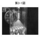
- FIG. 3A is a photograph showing the white smoke reduction state in the CO 2 absorption tower.
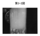
- FIG. 3-2 is a photograph showing a white smoke generation state in the CO 2 absorption tower.
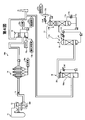
- FIG. 4 is a schematic diagram of the exhaust gas treatment system according to the first embodiment.
- FIG. 5 is a schematic diagram of another exhaust gas treatment system according to the first embodiment.
- FIG. 1 is a schematic diagram of an exhaust gas treatment system according to an embodiment of the present invention.
- the exhaust gas 12 from the boiler 11 is first removed from the nitrogen oxide (NOx) in the exhaust gas 12 by the denitration device 13 and then the air heater AH.
- NOx nitrogen oxide
- the air heater AH The air supplied to the boiler 11 by being led to is heated.
- the exhaust gas 12 is introduced into a dry electrostatic precipitator 14 which is a dust removing device, and dust is removed.
- the exhaust gas 12 is introduced into the desulfurizer 15 to remove sulfur oxides (SOx).
- the exhaust gas 12 is cooled by the cooling tower 16, it is introduced into the CO 2 recovery device 17 to remove carbon dioxide, and the purified gas 18 is released from the top of the CO 2 absorption tower to the atmosphere outside the system.
- the dust removed by the electric dust collector 14 is separately subjected to ash treatment 14a.
- mist generation substance removing apparatus for removing mist generating substance which is a source of mist generated in a CO 2 absorption tower of the CO 2 recovery apparatus 17 20 Is provided.
- the exhaust gas treatment system in prior to introducing the CO 2 recovering apparatus 17, is provided with the mist generator substance remover 20, the exhaust gas as it is introduced into the CO 2 absorber of CO 2 recovering apparatus 17
- the amount of mist generating substances in 12 is greatly reduced.
- the amount of the CO 2 absorbing liquid hereinafter also referred to as “absorbing liquid”
- the loss of the absorbing liquid scattered outside the system is greatly reduced, so that it is not replenished more than necessary, and an increase in running cost in exhaust gas treatment can be suppressed.
- the mist generating material removed by the mist generating material removing apparatus 20 according to the present invention is a SO 3 mist, nitric acid mist, hydrochloric acid mist, water vapor mist, etc., which is a substance that causes mist generation in the CO 2 absorption tower. .
- the apparatus which performs the removal in the gas state before becoming mist is also included in the mist generating substance removing apparatus 20 according to the present invention.
- the mist generating substance Since the exhaust gas 12 from the boiler 11 is in a high temperature state, the mist generating substance initially exists in a gas state. Thereafter, the exhaust gas is cooled in the process of passing through the electrostatic precipitator and the desulfurization device, so that the mist generating substance changes from the gas state to the mist state.
- the mist particle size of the mist generating substance is 3.0 ⁇ m or less.
- FIG. 2 is a conceptual diagram of the mechanism of the accompanying absorption liquid accompanying the generation of mist.
- Figure 3-1 photograph showing a white smoke relief state in the CO 2 absorption tower
- FIG. 3-2 is a photograph showing a white smoke generation state in the CO 2 absorption tower.
- SO 3 mist will be described as an example, but the same applies to other mists.
- the exhaust gas 12 from the boiler 11 is subjected to gas purification treatment such as denitration, dust removal and desulfurization, the exhaust gas 12 is cooled by the cooling tower 16, and the gas temperature becomes about 50 ° C. In this temperature state, since it is below the acid dew point, it is SO 3 mist (for example, 0.1 to 1.0 ⁇ m). In the SO 3 mist 50, SO 3 becomes a nucleus 51, and water vapor 52 is taken around the core 51.
- gas purification treatment such as denitration, dust removal and desulfurization
- the absorbing liquid is sprayed from the nozzle and falls, and CO 2 is absorbed by the absorbing liquid by bringing the falling absorbing liquid and exhaust gas into countercurrent contact.
- the exhaust gas 12 is introduced from below the CO 2 absorption tower and discharged upward. At this time, the SO 3 mist 50 is not absorbed by the absorption liquid and rises in the same manner as the gas flow of the exhaust gas 12.
- the absorbing liquid and water when the absorbing liquid is supplied from the nozzle, the absorbing liquid and water partially evaporate as the absorbing liquid falls, and gaseous absorbing liquid 41G and water vapor 42 are generated. Further, the gaseous absorbent 41G and the water vapor 42 further increase when the temperature of the absorbent rises due to, for example, the exothermic reaction of the absorbent when CO 2 is absorbed.
- an SO 3 mist (blowing mist) 53 containing an enlarged absorbent for example, about 0.5 to 2.0 ⁇ m
- the SO 3 mist 50 in the exhaust gas 12 before being introduced into the CO 2 recovery device 17 takes in the gaseous absorbent 41G and the water vapor 42 in the CO 2 absorption tower, and the SO 3 mist 53 containing the absorbent. And accompanying the exhaust gas 12, it is scattered from the top of the CO 2 absorption tower. Therefore, a loss of the absorbing liquid occurs.
- FIGS. 3-1 and 3-2 The state of white smoke generation in this CO 2 absorption tower is shown in FIGS. 3-1 and 3-2.
- the mist generating substance removing device 20 provided for the flue gas 12 to be introduced into the CO 2 absorption tower, a case with reduced amount of mist generation material below a predetermined amount, the CO 2 absorber the scattering of sO 3 mist (enlarged mist) 53 containing the absorbing liquid in the inner greatly reduced, showing a state in which generation of white smoke is suppressed.
- the mist generated in the CO 2 absorption tower refers to SO 3 mist (blowing mist) 53 containing an absorbing solution.
- SO 3 mist Blowing mist
- the presence or absence of the generation of this enlarged mist can be confirmed by the presence or absence of generation of white smoke.
- the generation of white smoke is eliminated, and consequently This prevents the absorption liquid from scattering.
- the enlarged mist is taken in by the gaseous absorbent 41G alone and the gaseous water vapor 42 alone in the CO 2 absorption tower with respect to the SO 3 mist 50 in the exhaust gas 12.
- SO 3 mists each containing absorption liquid (enlarged mist) 53A may become an SO 3 mist (enlarged mist) 53B containing water vapor.
- the mist (blowing mist) 53B containing water vapor although there is no loss of the absorption liquid, there is the generation of white smoke of the purified gas 18 discharged out of the system. Reduction is necessary.
- mist generated in a CO 2 absorption tower of the CO 2 recovery apparatus 17 SO 3 mists containing absorption liquid is enlarged mist
- mist generating substance removing device 20 that removes the mist generating substance that is the generation source of the gas, it is possible to significantly reduce the loss of the absorbing liquid scattered from the CO 2 absorption tower to the outside of the system.
- the mist generating substance removing device 20 is provided on the upstream side of the dry electrostatic precipitator 14, between the dry electrostatic precipitator 14 and the desulfurization device 15, before or after the cooling tower 16, or integrally with the cooling tower 16. You may do it.
- the SO 3 mist 50 is reduced to 3 ppm or less in order to prevent white smoke in the CO 2 absorption tower and scattering of the absorption liquid. preferable. This is because, when the SO 3 mist 50 is reduced to 3 ppm or less, the prevention of scattering is suppressed and, for example, the amine-based absorption liquid is prevented from being deteriorated by SO 3 .
- the absorption liquid is prevented from scattering and the absorption liquid is prevented from being deteriorated, it is possible to reduce the number of regeneration processes in the absorption liquid regenerating apparatus (reclaiming apparatus), and further, the absorption liquid loss Is greatly reduced, the amount of replenishment of the absorbent can be reduced. Therefore, the system efficiency of the exhaust gas treatment system can be greatly improved.
- the electrostatic precipitator has been described as an example of the dust removing device.
- the present invention is not limited to this as long as it removes the dust in the exhaust gas 12, and other than the electrostatic precipitator. Examples thereof include a bug filter and a venturi scrubber.
- FIG. 4 is a schematic diagram of the exhaust gas treatment system according to the first embodiment.
- FIG. 5 is a schematic diagram of another exhaust gas treatment system according to the first embodiment.
- SO 3 will be described as an example of a mist generating material, but the present invention is not limited to this.
- the exhaust gas treatment system 10 ⁇ / b> A according to the first embodiment includes a denitration device 13 that removes nitrogen oxides in the exhaust gas 12 from a boiler (for example, a coal fired boiler) 11 and a downstream side of the denitration device 13.
- a cooling tower 16 having a cooling section 16a for lowering the gas temperature, an absorption tower 17A for removing CO 2 in the exhaust gas 12 by contacting with the absorption liquid, and CO 2 from the absorption liquid to release CO 2.
- a CO 2 recovery device 17 composed of a regeneration tower 17B for regenerating the absorbing solution.
- a demister 26 is provided inside the cooling tower 16 as a measure for removing the mist generating substance.
- the demister 26 functions as the mist generating material removing device 20 shown in FIG.
- the SO 3 mist 50 in the exhaust gas 12 can be captured and removed.
- the amount of SO 3 mist introduced into the CO 2 recovery unit 17 is reduced as a result of removing SO 3 that is a mist generating substance in the exhaust gas 12 in a mist state. Therefore, the generation of white smoke of the purified gas 18 discharged from the absorption tower 17A due to mist is suppressed, and the accompanying of the absorbing liquid 41 is suppressed. As a result, it is possible to provide an exhaust gas treatment system in which the absorption liquid 41 is not lost.
- the wire diameter of the linear body constituting the demister 26 is preferably 1 to 20 ⁇ m, more preferably 3 to 10 ⁇ m, but the present invention is not limited to this.
- the space ratio of the demister 26 is preferably about 90 to 97%, but the present invention is not limited to this.
- the demister 26 is provided on the outlet side of the cooling tower 16, but an apparatus including the demister 26 may be separately installed on the downstream side of the cooling tower 16.
- the exhaust gas 12 from which dust is removed by the electrostatic precipitator 14 removes sulfur oxides in the exhaust gas 12 by a desulfurization device 15, and the removed sulfur oxides supply limestone (CaCO 3 ) 15a and oxidizing air 15b. Then, the lime / gypsum method is used to make the gypsum 15c, and the desulfurization drainage 15d is treated separately.
- reference numeral 17a represents a reboiler
- 17b represents saturated steam
- 17c represents condensed water
- 17d represents a separation drum
- 17e represents recovered CO 2
- 17f represents a heat exchanger.
- the exhaust gas 12 desulfurized by the desulfurization device 15 is cooled to an exhaust gas temperature of 50 ° C. or less by a cooling tower 16 and introduced into a CO 2 recovery device 17 composed of an absorption tower 17A and a regeneration tower 17B.
- CO 2 is removed by, for example, an amine-based absorption liquid 41.
- the amount of SO 3 mist introduced into the CO 2 recovery device 17 is reduced. Therefore, the generation of white smoke of the purified gas 18 discharged from the absorption tower 17A due to mist is suppressed, and the accompanying of the absorbing liquid 41 is suppressed. As a result, it is possible to provide an exhaust gas treatment system with no loss of absorption liquid.
- an amine-based absorbent is illustrated as the absorbent, but the absorbent of the present invention is not limited to the amine-based absorbent.
- the absorbent other than the amine-based absorbent include amino acid-based absorbent, ionic liquid absorbent, and hot potassium carbonate absorbent composed of potassium carbonate and amine.
- FIG. 5 is a schematic diagram of an exhaust gas treatment system according to a modification of the first embodiment.
- the exhaust gas 12 is cooled.
- a finishing desulfurization section 16b is provided in the lower part of the cooling tower 16, and limestone (CaCO 3 ) 15a and oxidizing air 15b are provided.
- the gypsum 15c is supplied by the lime / gypsum method.
- a strong alkaline agent such as sodium hydroxide (NaOH) may be added together with limestone.
- a liquid column type is used as a method for supplying the absorbing liquid for desulfurization, but the present invention is not limited to this, and any of a watering type, a jet type, and a filling type is used. be able to.
- a desulfurization absorbing solution used in the finish desulfurization section 16b in addition to limestone (CaCO 3 ), strong alkali such as NaOH, Na 2 CO 3 , NaHCO 3 , Ca (OH) 2 , Mg (OH) 2, etc. Agents can be exemplified.
- a strong alkali agent By using a strong alkali agent, it is possible to further improve the desulfurization performance.
- it is effective when the exhaust gas 12 having a high concentration of sulfur oxide is introduced, and the exhaust gas to be introduced into the CO 2 recovery device 17.
- the concentration of sulfur oxide in 12 can be made extremely low. Compared with the lime / gypsum method, the desulfurization performance is also improved, and even when the concentration of the sulfur oxide in the introduced exhaust gas 12 is high, the desulfurization performance is exhibited, which is preferable.
- the demister 26 is provided as the mist generating substance removing device 20. Therefore, when the exhaust gas 12 from which CO 2 has been removed is discharged to the outside, An exhaust gas treatment system that is not accompanied can be provided.
Landscapes
- Engineering & Computer Science (AREA)
- Chemical & Material Sciences (AREA)
- Nanotechnology (AREA)
- Environmental & Geological Engineering (AREA)
- Condensed Matter Physics & Semiconductors (AREA)
- Physics & Mathematics (AREA)
- General Physics & Mathematics (AREA)
- Crystallography & Structural Chemistry (AREA)
- Health & Medical Sciences (AREA)
- Biomedical Technology (AREA)
- Analytical Chemistry (AREA)
- General Chemical & Material Sciences (AREA)
- Oil, Petroleum & Natural Gas (AREA)
- Chemical Kinetics & Catalysis (AREA)
- Manufacturing & Machinery (AREA)
- Composite Materials (AREA)
- Materials Engineering (AREA)
- Treating Waste Gases (AREA)
- Gas Separation By Absorption (AREA)
Abstract
Description
このようなCO2吸収液の系外への飛散がある場合には、CO2吸収液の大幅なロスにつながると共に、CO2吸収液を必要以上に補充することとなるので、系外へCO2吸収液が飛散することを抑制する必要がある。
図1に示すように、本発明に係る実施形態の排ガス処理システム10において、ボイラ11からの排ガス12は、脱硝装置13で排ガス12中の窒素酸化物(NOx)を除去した後、まずエアヒータAHに導かれてボイラ11に供給される空気を加熱する。その後排ガス12は、除塵装置である乾式の電気集塵機14に導入されて煤塵が除去される。次に、排ガス12は、脱硫装置15に導入されて硫黄酸化物(SOx)が除去される。次いで、排ガス12は冷却塔16で冷却された後、CO2回収装置17に導入されて、二酸化炭素を除去し、CO2吸収塔の塔頂部から浄化ガス18が系外である大気に放出される。なお、電気集塵機14で除去された煤塵は別途灰処理14aされる。
本発明でミスト発生物質のミストの粒径は、3.0μm以下をいう。
図2は、ミスト発生に伴う吸収液の同伴のメカニズムの概念図である。図3−1は、CO2吸収塔内での白煙軽減状態を示す写真、図3−2は、CO2吸収塔内での白煙発生状態を示す写真である。ミスト発生物質として、SO3ミストを例にして説明するが、他のミストでも同様である。ボイラ11からの排ガス12は、脱硝、煤塵除去及び脱硫等のガス浄化処理がなされ、冷却塔16で排ガス12が冷却され、ガス温度は50℃程度となる。この温度状態では、酸露点以下であるので、SO3ミスト(例えば0.1~1.0μm)となっている。
このSO3ミスト50は、SO3が核51となり、その周囲に水蒸気52が取り込まれたものである。
また、このガス状吸収液41G及び水蒸気42は、CO2を吸収する際の例えば吸収液の発熱反応により吸収液の温度が上昇することで更に増加する。
図3−1では、CO2吸収塔内に導入する排ガス12に対してミスト発生物質除去装置20を設けて、所定量以下にミスト発生物質の量を低減させた場合であり、CO2吸収塔内での吸収液を含むSO3ミスト(肥大化ミスト)53の飛散を大幅に低減し、白煙の発生が抑制されている状態を示す。図3−2では、CO2吸収塔内に導入する排ガス12に対してミスト発生物質除去装置20を設けずに、排ガス12をそのまま導入した場合であり、CO2吸収塔内での吸収液を含むSO3ミスト(肥大化ミスト)53の飛散が生じ、白煙が発生している状態を示す。
この際、水蒸気を含むミスト(肥大化ミスト)53Bの場合には、吸収液のロスは無いものの、系外への排出する浄化ガス18の白煙の発生があるので、やはり、ミスト発生物質の低減が必要となる。
よって、本発明によれば、CO2回収装置17に導入する以前において、ミスト発生物質除去装置20を設けることにより、系外にCO2を除去した排ガス12を排出する際に、CO2吸収液の同伴を大幅に低減すると共に、適正な排ガス処理を行うことができるものとなる。
ここで、CO2回収装置17に排ガス12をその導入する以前において、SO3ミスト50を3ppm以下まで低減するのが、CO2吸収塔内での白煙防止及び吸収液の飛散防止のために好ましい。これは、SO3ミスト50を3ppm以下まで低減すると、飛散防止を抑制すると共に、例えばアミン系の吸収液がSO3により劣化するのを防止するためでもある。
図4に示すように、実施例1に係る排ガス処理システム10Aは、ボイラ(例えば石炭焚ボイラ)11からの排ガス12中の窒素酸化物を除去する脱硝装置13と、脱硝装置13の後流側に設けられ、排ガス12中の煤塵を除去する電気集塵機14と、電気集塵機14の後流側に設けられ、排ガス12中の硫黄酸化物を除去する脱硫装置15と、脱硫装置15の後流側に設けられ、ガス温度を下げる冷却部16aを有する冷却塔16と、前記排ガス12中のCO2を吸収液に接触させて除去する吸収塔17Aと、吸収液からCO2を放出してCO2を回収すると共に、吸収液を再生する再生塔17BとからなるCO2回収装置17とを具備するものである。
この結果、吸収液のロスの無い排ガス処理システムを提供することができる。
本実施例では、仕上げ脱硫部16bにおいて、脱硫用吸収液の供給方法として、液柱式を用いているが、本発明はこれに限定されず、散水式、噴流式、充填式のいずれも用いることができる。
11 ボイラ
12 排ガス
13 脱硝装置
14 電気集塵機
15 脱硫装置
16 冷却塔
16a 冷却部
16b 仕上げ脱硫部
17 CO2回収装置
17A 吸収塔
17B 再生塔
18 浄化ガス
20 ミスト発生物質除去装置
26 デミスタ
Claims (4)
- ボイラからの排ガス中の硫黄酸化物を除去する脱硫装置と、
前記脱硫装置の後流側に設けられ、排ガス中に残存する硫黄酸化物を除去すると共に、ガス温度を下げる冷却塔と、
前記排ガス中のCO2をCO2吸収液に接触させて除去する吸収塔と、CO2吸収液からCO2を放出してCO2を回収すると共に、CO2吸収液を再生する再生塔とからなるCO2回収装置と、
前記CO2回収装置に排ガスを導入する以前において、CO2回収装置の吸収塔内で発生するミストの発生源であるミスト発生物質を除去するデミスタと
を具備することを特徴とする排ガス処理システム。 - 請求項1において、
排ガス中の窒素酸化物を除去する脱硝装置と、煤塵を除去する乾式電気集塵機とを有することを特徴とする排ガス処理システム。 - 請求項1又は2において、
デミスタが冷却塔の塔頂部に有することを特徴とする排ガス処理システム。 - 排ガス中のCO2をCO2吸収液に接触させて吸収・除去するCO2回収装置の前流側において、
排ガス中の温度を低下させる冷却塔の出口側又は後流側で、排ガス中のミストをデミスタで捕獲し、
前記CO2回収装置に導入する排ガス中のミスト発生物質の量を所定量以下に低減することを特徴とする排ガス処理方法。
Priority Applications (5)
| Application Number | Priority Date | Filing Date | Title |
|---|---|---|---|
| EP11789946.8A EP2578293A4 (en) | 2010-05-31 | 2011-05-31 | SYSTEM AND METHOD FOR TREATING EXHAUST GAS |
| CA2800994A CA2800994C (en) | 2010-05-31 | 2011-05-31 | Air pollution control system and method |
| JP2012518476A JPWO2011152546A1 (ja) | 2010-05-31 | 2011-05-31 | 排ガス処理システム及び方法 |
| US13/701,087 US20130142712A1 (en) | 2010-05-31 | 2011-05-31 | Air pollution control system and method |
| AU2011259873A AU2011259873B2 (en) | 2010-05-31 | 2011-05-31 | Air pollution control system and method |
Applications Claiming Priority (2)
| Application Number | Priority Date | Filing Date | Title |
|---|---|---|---|
| JP2010125389 | 2010-05-31 | ||
| JP2010-125389 | 2010-05-31 |
Publications (1)
| Publication Number | Publication Date |
|---|---|
| WO2011152546A1 true WO2011152546A1 (ja) | 2011-12-08 |
Family
ID=45066900
Family Applications (1)
| Application Number | Title | Priority Date | Filing Date |
|---|---|---|---|
| PCT/JP2011/062866 Ceased WO2011152546A1 (ja) | 2010-05-31 | 2011-05-31 | 排ガス処理システム及び方法 |
Country Status (6)
| Country | Link |
|---|---|
| US (1) | US20130142712A1 (ja) |
| EP (1) | EP2578293A4 (ja) |
| JP (1) | JPWO2011152546A1 (ja) |
| AU (1) | AU2011259873B2 (ja) |
| CA (1) | CA2800994C (ja) |
| WO (1) | WO2011152546A1 (ja) |
Cited By (5)
| Publication number | Priority date | Publication date | Assignee | Title |
|---|---|---|---|---|
| WO2014057567A1 (ja) * | 2012-10-11 | 2014-04-17 | 三菱重工業株式会社 | 排ガス処理システム及び方法 |
| US8871164B2 (en) | 2010-05-31 | 2014-10-28 | Mitsubushi Heavy Industries, Ltd. | Air pollution control system and method |
| US8894941B2 (en) | 2010-05-31 | 2014-11-25 | Mitsubishi Heavy Industries, Ltd. | Air pollution control system and method |
| US9381461B2 (en) | 2010-05-31 | 2016-07-05 | Mitsubishi Heavy Industries, Ltd. | Air pollution control system and method |
| US10835862B2 (en) | 2010-05-31 | 2020-11-17 | Mitsubishi Heavy Industries Engineering, Ltd. | Air pollution control system and method |
Families Citing this family (5)
| Publication number | Priority date | Publication date | Assignee | Title |
|---|---|---|---|---|
| US10295147B2 (en) | 2006-11-09 | 2019-05-21 | Cree, Inc. | LED array and method for fabricating same |
| US10842016B2 (en) | 2011-07-06 | 2020-11-17 | Cree, Inc. | Compact optically efficient solid state light source with integrated thermal management |
| DE102013015280A1 (de) * | 2013-09-16 | 2015-03-19 | Rwe Power Aktiengesellschaft | Verfahren und System zur Gaswäsche von aerosolhaltigen Prozessgasen |
| WO2019028558A1 (en) | 2017-08-11 | 2019-02-14 | Co2 Solutions Inc. | SOX CAPTURE USING CARBONATE ABSORBENT |
| US11484825B1 (en) * | 2021-12-20 | 2022-11-01 | Next Carbon Solutions, Llc | Devices, systems, facilities and processes for carbon capture optimization in industrial facilities |
Citations (2)
| Publication number | Priority date | Publication date | Assignee | Title |
|---|---|---|---|---|
| JP2005087828A (ja) * | 2003-09-16 | 2005-04-07 | Kansai Electric Power Co Inc:The | 脱硫脱炭酸方法及びその装置 |
| JP2009195860A (ja) * | 2008-02-22 | 2009-09-03 | Hitachi Plant Technologies Ltd | 排ガス処理方法及び装置 |
Family Cites Families (16)
| Publication number | Priority date | Publication date | Assignee | Title |
|---|---|---|---|---|
| DE2050580C3 (de) * | 1970-10-15 | 1979-09-06 | Metallgesellschaft Ag, 6000 Frankfurt | Vorrichtung zur Absorption von gasförmigen Bestandteilen |
| BE788625A (fr) * | 1971-09-11 | 1973-01-02 | Metallgesellschaft Ag | Procede d'elimination de l'anhydride sulfurique et des brouillards d'acide sulfurique contenus dans des gaz |
| DE2322982C3 (de) * | 1973-05-08 | 1979-09-13 | Metallgesellschaft Ag, 6000 Frankfurt | Verfahren zur Entfernung von gasförmigen Verunreinigungen aus Abgasen von Schwefelsäurekontaktanlagen |
| DK145457C (da) * | 1980-03-25 | 1983-04-18 | Haldor Topsoe As | Fremgangsmaade til fremstilling af svovlsyre,ved hvilken maengden af svovlsyretaage i afgangsgassen styres ved temperaturregulering |
| IL122015A (en) * | 1997-10-22 | 2003-04-10 | Clue As | Scrubber for the treatment of flue gases |
| US6174510B1 (en) * | 1999-08-27 | 2001-01-16 | Marcos D. Riano | Multi-pass cocurrent flow sulfuric acid tower process |
| DE10305578A1 (de) * | 2003-02-11 | 2004-08-19 | Basf Ag | Verfahren und Vorrichtung zur Reduzierung des aerosolbedingten Austrages aus einer Trennkolonne |
| JP4959303B2 (ja) * | 2006-11-21 | 2012-06-20 | 三菱重工業株式会社 | 排気ガスの処理方法及び処理装置 |
| DE102007020855A1 (de) * | 2007-05-02 | 2008-11-06 | Evonik Energy Services Gmbh | Verfahren zum Reinigen von Rauchgasen aus Verbrennungsanlagen |
| DE102007043331A1 (de) * | 2007-08-16 | 2009-02-19 | Hitachi Power Europe Gmbh | Gekühlte NaOH-Rauchgaswäsche |
| US20110052453A1 (en) * | 2008-01-18 | 2011-03-03 | Mclarnon Christopher | Removal of carbon dioxide from a flue gas stream |
| US7927573B2 (en) * | 2008-09-26 | 2011-04-19 | Praxair Technology, Inc. | Multi-stage process for purifying carbon dioxide and producing acid |
| FR2946417A1 (fr) * | 2009-06-03 | 2010-12-10 | Air Liquide | Procede et appareil de production d'au moins un fluide enrichi en argon et/ou au moins un fluide enrichi en oxygene a partir d'un fluide residuaire |
| JP5093205B2 (ja) * | 2009-09-30 | 2012-12-12 | 株式会社日立製作所 | 二酸化炭素回収型発電システム |
| WO2011108086A1 (ja) * | 2010-03-03 | 2011-09-09 | バブコック日立株式会社 | 二酸化炭素除去装置を備えた排ガス処理システム |
| US8501130B1 (en) * | 2012-09-24 | 2013-08-06 | Mitsubishi Heavy Industries, Ltd. | Carbon dioxide recovery system and method |
-
2011
- 2011-05-31 JP JP2012518476A patent/JPWO2011152546A1/ja active Pending
- 2011-05-31 EP EP11789946.8A patent/EP2578293A4/en not_active Withdrawn
- 2011-05-31 WO PCT/JP2011/062866 patent/WO2011152546A1/ja not_active Ceased
- 2011-05-31 AU AU2011259873A patent/AU2011259873B2/en active Active
- 2011-05-31 US US13/701,087 patent/US20130142712A1/en not_active Abandoned
- 2011-05-31 CA CA2800994A patent/CA2800994C/en active Active
Patent Citations (2)
| Publication number | Priority date | Publication date | Assignee | Title |
|---|---|---|---|---|
| JP2005087828A (ja) * | 2003-09-16 | 2005-04-07 | Kansai Electric Power Co Inc:The | 脱硫脱炭酸方法及びその装置 |
| JP2009195860A (ja) * | 2008-02-22 | 2009-09-03 | Hitachi Plant Technologies Ltd | 排ガス処理方法及び装置 |
Non-Patent Citations (1)
| Title |
|---|
| See also references of EP2578293A4 * |
Cited By (9)
| Publication number | Priority date | Publication date | Assignee | Title |
|---|---|---|---|---|
| US8871164B2 (en) | 2010-05-31 | 2014-10-28 | Mitsubushi Heavy Industries, Ltd. | Air pollution control system and method |
| US8894941B2 (en) | 2010-05-31 | 2014-11-25 | Mitsubishi Heavy Industries, Ltd. | Air pollution control system and method |
| US9381461B2 (en) | 2010-05-31 | 2016-07-05 | Mitsubishi Heavy Industries, Ltd. | Air pollution control system and method |
| US10835862B2 (en) | 2010-05-31 | 2020-11-17 | Mitsubishi Heavy Industries Engineering, Ltd. | Air pollution control system and method |
| WO2014057567A1 (ja) * | 2012-10-11 | 2014-04-17 | 三菱重工業株式会社 | 排ガス処理システム及び方法 |
| JPWO2014057567A1 (ja) * | 2012-10-11 | 2016-08-25 | 三菱重工業株式会社 | 排ガス処理システム及び方法 |
| AU2012391846B2 (en) * | 2012-10-11 | 2016-10-13 | Mitsubishi Heavy Industries, Ltd. | Exhaust gas treatment system and method |
| US9568193B2 (en) | 2012-10-11 | 2017-02-14 | Mitsubishi Heavy Industries, Ltd. | Air pollution control system and air pollution control method |
| EP3685907A1 (en) | 2012-10-11 | 2020-07-29 | Mitsubishi Heavy Industries Engineering, Ltd. | Air pollution control system and air pollution control method |
Also Published As
| Publication number | Publication date |
|---|---|
| EP2578293A4 (en) | 2015-01-28 |
| US20130142712A1 (en) | 2013-06-06 |
| JPWO2011152546A1 (ja) | 2013-08-01 |
| AU2011259873A1 (en) | 2012-12-20 |
| CA2800994A1 (en) | 2011-12-08 |
| CA2800994C (en) | 2015-12-08 |
| AU2011259873B2 (en) | 2014-08-14 |
| EP2578293A1 (en) | 2013-04-10 |
Similar Documents
| Publication | Publication Date | Title |
|---|---|---|
| JP6045652B2 (ja) | Co2吸収液の飛散抑制方法 | |
| JP6045653B2 (ja) | Co2吸収液の飛散抑制方法 | |
| JP6045654B2 (ja) | Co2吸収液の飛散抑制方法 | |
| JP6104992B2 (ja) | Co2吸収液の飛散抑制方法 | |
| WO2011152552A1 (ja) | 排ガス処理システム及び方法 | |
| JPWO2011152546A1 (ja) | 排ガス処理システム及び方法 | |
| WO2011152547A1 (ja) | 排ガス処理システム及び方法 | |
| WO2014057567A1 (ja) | 排ガス処理システム及び方法 | |
| JP5755047B2 (ja) | 排ガス処理システム及び排ガス処理方法 |
Legal Events
| Date | Code | Title | Description |
|---|---|---|---|
| 121 | Ep: the epo has been informed by wipo that ep was designated in this application |
Ref document number: 11789946 Country of ref document: EP Kind code of ref document: A1 |
|
| WWE | Wipo information: entry into national phase |
Ref document number: 2012518476 Country of ref document: JP |
|
| ENP | Entry into the national phase |
Ref document number: 2800994 Country of ref document: CA |
|
| WWE | Wipo information: entry into national phase |
Ref document number: 10043/CHENP/2012 Country of ref document: IN |
|
| NENP | Non-entry into the national phase |
Ref country code: DE |
|
| WWE | Wipo information: entry into national phase |
Ref document number: 2011789946 Country of ref document: EP |
|
| ENP | Entry into the national phase |
Ref document number: 2011259873 Country of ref document: AU Date of ref document: 20110531 Kind code of ref document: A |
|
| WWE | Wipo information: entry into national phase |
Ref document number: 13701087 Country of ref document: US |