WO2011158470A1 - 通信装置及び通信方法 - Google Patents
通信装置及び通信方法 Download PDFInfo
- Publication number
- WO2011158470A1 WO2011158470A1 PCT/JP2011/003262 JP2011003262W WO2011158470A1 WO 2011158470 A1 WO2011158470 A1 WO 2011158470A1 JP 2011003262 W JP2011003262 W JP 2011003262W WO 2011158470 A1 WO2011158470 A1 WO 2011158470A1
- Authority
- WO
- WIPO (PCT)
- Prior art keywords
- power
- value
- period
- communication
- beacon
- Prior art date
- Legal status (The legal status is an assumption and is not a legal conclusion. Google has not performed a legal analysis and makes no representation as to the accuracy of the status listed.)
- Ceased
Links
Images




















Classifications
-
- H—ELECTRICITY
- H04—ELECTRIC COMMUNICATION TECHNIQUE
- H04W—WIRELESS COMMUNICATION NETWORKS
- H04W52/00—Power management, e.g. Transmission Power Control [TPC] or power classes
- H04W52/02—Power saving arrangements
- H04W52/0209—Power saving arrangements in terminal devices
- H04W52/0212—Power saving arrangements in terminal devices managed by the network, e.g. network or access point is leader and terminal is follower
- H04W52/0216—Power saving arrangements in terminal devices managed by the network, e.g. network or access point is leader and terminal is follower using a pre-established activity schedule, e.g. traffic indication frame
-
- H—ELECTRICITY
- H04—ELECTRIC COMMUNICATION TECHNIQUE
- H04W—WIRELESS COMMUNICATION NETWORKS
- H04W52/00—Power management, e.g. Transmission Power Control [TPC] or power classes
- H04W52/02—Power saving arrangements
- H04W52/0209—Power saving arrangements in terminal devices
- H04W52/0251—Power saving arrangements in terminal devices using monitoring of local events, e.g. events related to user activity
- H04W52/0258—Power saving arrangements in terminal devices using monitoring of local events, e.g. events related to user activity controlling an operation mode according to history or models of usage information, e.g. activity schedule or time of day
-
- H—ELECTRICITY
- H04—ELECTRIC COMMUNICATION TECHNIQUE
- H04W—WIRELESS COMMUNICATION NETWORKS
- H04W52/00—Power management, e.g. Transmission Power Control [TPC] or power classes
- H04W52/02—Power saving arrangements
- H04W52/0209—Power saving arrangements in terminal devices
- H04W52/0261—Power saving arrangements in terminal devices managing power supply demand, e.g. depending on battery level
- H04W52/0274—Power saving arrangements in terminal devices managing power supply demand, e.g. depending on battery level by switching on or off the equipment or parts thereof
- H04W52/0277—Power saving arrangements in terminal devices managing power supply demand, e.g. depending on battery level by switching on or off the equipment or parts thereof according to available power supply, e.g. switching off when a low battery condition is detected
-
- H—ELECTRICITY
- H02—GENERATION; CONVERSION OR DISTRIBUTION OF ELECTRIC POWER
- H02J—ELECTRIC POWER NETWORKS; CIRCUIT ARRANGEMENTS OR SYSTEMS FOR SUPPLYING OR DISTRIBUTING ELECTRIC POWER; SYSTEMS FOR STORING ELECTRIC ENERGY
- H02J2105/00—Networks for supplying or distributing electric power characterised by their spatial reach or by the load
- H02J2105/40—Networks for supplying or distributing electric power characterised by their spatial reach or by the load characterised by the loads connecting to the networks or being supplied by the networks
- H02J2105/42—Home appliances
-
- Y—GENERAL TAGGING OF NEW TECHNOLOGICAL DEVELOPMENTS; GENERAL TAGGING OF CROSS-SECTIONAL TECHNOLOGIES SPANNING OVER SEVERAL SECTIONS OF THE IPC; TECHNICAL SUBJECTS COVERED BY FORMER USPC CROSS-REFERENCE ART COLLECTIONS [XRACs] AND DIGESTS
- Y02—TECHNOLOGIES OR APPLICATIONS FOR MITIGATION OR ADAPTATION AGAINST CLIMATE CHANGE
- Y02B—CLIMATE CHANGE MITIGATION TECHNOLOGIES RELATED TO BUILDINGS, e.g. HOUSING, HOUSE APPLIANCES OR RELATED END-USER APPLICATIONS
- Y02B70/00—Technologies for an efficient end-user side electric power management and consumption
- Y02B70/30—Systems integrating technologies related to power network operation and communication or information technologies for improving the carbon footprint of the management of residential or tertiary loads, i.e. smart grids as climate change mitigation technology in the buildings sector, including also the last stages of power distribution and the control, monitoring or operating management systems at local level
-
- Y—GENERAL TAGGING OF NEW TECHNOLOGICAL DEVELOPMENTS; GENERAL TAGGING OF CROSS-SECTIONAL TECHNOLOGIES SPANNING OVER SEVERAL SECTIONS OF THE IPC; TECHNICAL SUBJECTS COVERED BY FORMER USPC CROSS-REFERENCE ART COLLECTIONS [XRACs] AND DIGESTS
- Y02—TECHNOLOGIES OR APPLICATIONS FOR MITIGATION OR ADAPTATION AGAINST CLIMATE CHANGE
- Y02B—CLIMATE CHANGE MITIGATION TECHNOLOGIES RELATED TO BUILDINGS, e.g. HOUSING, HOUSE APPLIANCES OR RELATED END-USER APPLICATIONS
- Y02B70/00—Technologies for an efficient end-user side electric power management and consumption
- Y02B70/30—Systems integrating technologies related to power network operation and communication or information technologies for improving the carbon footprint of the management of residential or tertiary loads, i.e. smart grids as climate change mitigation technology in the buildings sector, including also the last stages of power distribution and the control, monitoring or operating management systems at local level
- Y02B70/3225—Demand response systems, e.g. load shedding, peak shaving
-
- Y—GENERAL TAGGING OF NEW TECHNOLOGICAL DEVELOPMENTS; GENERAL TAGGING OF CROSS-SECTIONAL TECHNOLOGIES SPANNING OVER SEVERAL SECTIONS OF THE IPC; TECHNICAL SUBJECTS COVERED BY FORMER USPC CROSS-REFERENCE ART COLLECTIONS [XRACs] AND DIGESTS
- Y02—TECHNOLOGIES OR APPLICATIONS FOR MITIGATION OR ADAPTATION AGAINST CLIMATE CHANGE
- Y02D—CLIMATE CHANGE MITIGATION TECHNOLOGIES IN INFORMATION AND COMMUNICATION TECHNOLOGIES [ICT], I.E. INFORMATION AND COMMUNICATION TECHNOLOGIES AIMING AT THE REDUCTION OF THEIR OWN ENERGY USE
- Y02D30/00—Reducing energy consumption in communication networks
- Y02D30/70—Reducing energy consumption in communication networks in wireless communication networks
-
- Y—GENERAL TAGGING OF NEW TECHNOLOGICAL DEVELOPMENTS; GENERAL TAGGING OF CROSS-SECTIONAL TECHNOLOGIES SPANNING OVER SEVERAL SECTIONS OF THE IPC; TECHNICAL SUBJECTS COVERED BY FORMER USPC CROSS-REFERENCE ART COLLECTIONS [XRACs] AND DIGESTS
- Y04—INFORMATION OR COMMUNICATION TECHNOLOGIES HAVING AN IMPACT ON OTHER TECHNOLOGY AREAS
- Y04S—SYSTEMS INTEGRATING TECHNOLOGIES RELATED TO POWER NETWORK OPERATION, COMMUNICATION OR INFORMATION TECHNOLOGIES FOR IMPROVING THE ELECTRICAL POWER GENERATION, TRANSMISSION, DISTRIBUTION, MANAGEMENT OR USAGE, i.e. SMART GRIDS
- Y04S20/00—Management or operation of end-user stationary applications or the last stages of power distribution; Controlling, monitoring or operating thereof
- Y04S20/20—End-user application control systems
- Y04S20/222—Demand response systems, e.g. load shedding, peak shaving
-
- Y—GENERAL TAGGING OF NEW TECHNOLOGICAL DEVELOPMENTS; GENERAL TAGGING OF CROSS-SECTIONAL TECHNOLOGIES SPANNING OVER SEVERAL SECTIONS OF THE IPC; TECHNICAL SUBJECTS COVERED BY FORMER USPC CROSS-REFERENCE ART COLLECTIONS [XRACs] AND DIGESTS
- Y04—INFORMATION OR COMMUNICATION TECHNOLOGIES HAVING AN IMPACT ON OTHER TECHNOLOGY AREAS
- Y04S—SYSTEMS INTEGRATING TECHNOLOGIES RELATED TO POWER NETWORK OPERATION, COMMUNICATION OR INFORMATION TECHNOLOGIES FOR IMPROVING THE ELECTRICAL POWER GENERATION, TRANSMISSION, DISTRIBUTION, MANAGEMENT OR USAGE, i.e. SMART GRIDS
- Y04S20/00—Management or operation of end-user stationary applications or the last stages of power distribution; Controlling, monitoring or operating thereof
- Y04S20/20—End-user application control systems
- Y04S20/242—Home appliances
Definitions
- the present invention relates to an IEEE (Institut of Electrical and Electronics Engineers) 802.11 standard WLAN (Wireless Local Area Network) or an IEEE 802.15 standard WPAN (WirelessPerson network method). Is.
- FIG. 43 is a diagram illustrating an example of a conventional wireless network configuration.
- the wireless network includes a control station 1001 that is a wireless control station and terminal devices 1002, 1003, and 1004 that are a plurality of wireless terminal devices.
- the control station 1001 periodically broadcasts control information in a beacon packet to the terminal devices 1002 to 1004.
- the terminal devices 1002 to 1004 communicate with the control station 1001 based on this control information.
- CSMA Carrier Sense Multiple Access
- TDMA Time Division Multiple Access
- FDMA Frequency-Division Multiple Access
- the wireless devices (control stations 1001 and 1002 to 1004 terminal devices) used in these wireless networks are characterized by low power consumption performance. For example, in order to reduce the power consumption of the wireless device, an active period in which communication is performed in the wireless network and an inactive period in which a sleep state can be entered without performing communication are provided. If the inactive period is lengthened, the sleep state can be lengthened, so that power consumption can be reduced.
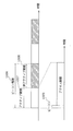
- FIG. 44 shows an example of the frame period.
- FIG. 3 is a diagram showing a relationship between a conventional beacon period, an active period, and an inactive period.
- one frame period includes an active period 1007 and an inactive period 1008.
- the active period 1007 is a period during which the control station 1001 and the terminal devices 1002 to 1004 communicate.
- the inactive period 1008 is a period in which the control station 1001 and the terminal devices 1002 to 1004 do not communicate. During this period, the control station 1001 and the terminal devices 1002 to 1004 reduce power consumption by entering the sleep state. Can do. Even in the active period 1007, a terminal device that does not perform communication can reduce power consumption by entering a sleep state.
- the control station 1001 and the terminal devices 1002 to 1004 share the active period.
- the control station 1001 broadcasts a beacon frame 1009 using the first period of the active period. That is, the beacon period 1006 is the sum of the active period 1007 and the inactive period 1008.
- the active period other than broadcasting the beacon frame is used for communication between the control station 1001 and the terminal devices 1002 to 1004, and for example, CSMA can be used.
- the active period may be divided into a plurality of time slots, and the slots may be shared by slots CSMA and TDMA.
- the time slot in the first half of the active period is used for contention access by CSMA
- the time slot in the second half of the active period is used for communication to which a radio apparatus to be used for each time slot is assigned. .
- the beacon frame includes control information about the frame such as the number of these time slots and their allocation, the length of the active period, the length of the inactive period, and the time until the next beacon frame transmission.
- FIG. 45 is a flowchart showing an example of a sequence for performing data communication from the conventional control station 1001 to the terminal device 1002.
- the control station 1001 buffers the data.
- the control station 1001 adds information buffering data to be transmitted to the terminal device 1002 to the beacon frame.
- the IEEE 802.15.4 standard adds a Data Pending Address List to the beginning of the active period. Broadcast a beacon frame (S1011).
- the control station 1001 adds a TIM (Traffic Indication Message) instead of adding a Data Pending Address List, and broadcasts a beacon frame at the beginning of the active period.
- the terminal device 1002 changes from the sleep state to the activated state at the timing of receiving the beacon frame, and receives the beacon frame (S1011).
- the beacon frame includes the length of the active period, the length of the inactive period, the time until transmission of the next beacon frame, Data Pending information, and the like.
- the terminal device 1002 always changes to the activated state at the timing of receiving the beacon frame and receives the beacon frame.
- the terminal device 1002 When the terminal device 1002 analyzes the Data Pending information of the beacon frame (S1012) and recognizes that there is data addressed to itself, it transmits a data request to the control station 1001 (S1013). Upon receiving the data request (S1013), the control station 1001 transmits the buffered data to the terminal device 1002 (S1014), and the terminal device 1002 returns an ACK that is an arrival confirmation signal to the control station 1001 ( S1015).
- the terminal device 1002 changes from the sleep state to the activated state at the timing of receiving a periodically transmitted beacon frame, and checks whether there is data addressed to itself based on the beacon frame. If there is data addressed to itself, the terminal device 1002 receives the data after making an inquiry to the control station, and enters the sleep state until the next beacon frame reception timing. On the other hand, if there is no data addressed to the local station in the beacon frame, the terminal device 1002 immediately enters the sleep state until the next beacon frame reception timing. With this operation, the power consumption of the terminal device 1002 is reduced.
- a method of setting the sleep state time of the terminal device 1002 to be long and extending the cycle of the beacon frame can be considered.
- the buffering time in the control station 1001 becomes long, and the delay time until the data reaches the terminal device 1002 becomes long. This has the problem of causing problems for applications that require real-time performance and immediateness.
- Patent Document 1 first determines whether data traffic is periodic (stream) or continuous (burst) by taking statistics of the time information history of the data frame received by the terminal device.
- the data received by the terminal device is periodic (stream) data
- the transmission period of the beacon frame from the control station is changed in accordance with the data reception interval.
- the data received by the terminal device is continuous (burst) data
- the delay of data reception is suppressed, real-time property is maintained, and the improvement in the power saving effect is realized.
- Patent Document 1 it is necessary to discriminate between stream data and burst data, a period in which data transfer continues continuously, and a period in which data transfer stops for a while based on statistics of data frame reception history. is there.
- an example of an application having no regularity of data is peak suppression in EMS (Energy Management System).
- FIG. 46 is a diagram illustrating an example of a network configuration for realizing an in-house EMS application.
- the energy controller 1021 has a function of a radio control station.
- Network home appliances 1022, 1023, and 1024 have a function of a wireless terminal device.
- the distribution board 1025 can measure the total power consumption in the home and notifies the energy controller 1021 of the information.
- the total power consumption is the total power consumed by a plurality of devices such as home appliances at the same time and consumed by these devices.
- the unit is, for example, watts (W).
- Wh watt hour
- kWh kilowatt hour
- Network home appliances are home appliances that have a communication function and are connected to a network.
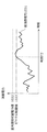
- FIG. 47A and 47B are diagrams showing an example of the correspondence between total power consumption and time. Specifically, FIG. 47A is an example showing temporal variation of the total power consumption 1031 in the home. FIG. 47B is an example showing temporal variation of the total power consumption 1031 at the time of peak suppression execution.
- the dotted line indicates the maximum usable power value 1032.
- the maximum usable power value 1032 is, for example, an allowable amount of a breaker (breaker) of a distribution board, a supply amount from an electric power company, an electricity rate fluctuation boundary line, a private power generation supply amount by a solar power generation device or a fuel cell device, and the like. is there.
- the maximum usable power value 1032 is an example of the allowable amount of the breaker of the distribution board.
- the breaker falls and the power supply to the operating device stops.
- the power is turned off during operation.
- a peak suppression in which the operation status and total power consumption of each device are grasped in real time, and the total power consumption 1031 is controlled so as not to exceed the maximum usable power value 1032.
- a peak suppression threshold 1033 smaller than the maximum usable power value 1032 is provided.
- the energy controller 1021 suppresses the total power consumption 1031 by remotely operating the network home appliances 1022 to 1024 to turn off the power or change the setting items.
- the total power consumption 1031 can be suppressed by turning off the power supply of home appliances such as lighting and television, changing the set temperature of the air conditioner, changing the high wind mode of the air conditioner to the power saving mode, or lowering the illuminance of the illumination. Is possible.
- FIG. 47B shows that the total power used 1031 exceeds the peak suppression threshold 1033 at time T2.
- this figure is an example in which the total power consumption 1031 does not exceed the maximum usable power value 1032 by performing peak suppression.
- EMS peak suppression requires low-latency control, and the total power consumption changes over time depending on various factors such as each household, time zone, region, season, climate, and country. It is not easy to statistically learn the regularity of. Therefore, in applications such as peak suppression without data regularity, there is a problem that it is difficult to achieve both low power consumption and real-time characteristics (low delay, immediacy) of the communication terminal device.
- the present invention solves the above-described conventional problems, and a communication apparatus and communication capable of achieving both low power consumption and real-time performance of a communication terminal apparatus even in applications such as peak suppression without data regularity. It aims to provide a method.
- a communication device configured such that a communication terminal device that repeats a start-up state in which communication is possible and a sleep state in which communication is not possible is in a start-up state.
- the transmission cycle is determined so that the transmission cycle for transmitting the signal becomes longer as the differential power value, which is a value obtained by subtracting the total power consumption value of the power consuming device from the suppliable power value, increases.
- a power control unit the communication terminal device including the signal including information indicating the determined transmission cycle
- a communication interface unit for transmitting is configured such that a communication terminal device that repeats a start-up state in which communication is possible and a sleep state in which communication is not possible is in a start-up state.
- the communication device as the control station has a transmission cycle determined to be longer as the difference power value obtained by subtracting the total power consumption value of the power consuming device from the suppliable power value to the power consuming device is larger.
- a signal including the information to be transmitted is transmitted to the communication terminal device. That is, the signal transmission cycle is calculated based on the remaining usable power information.
- peak suppression for controlling the total power consumption value so as not to exceed the suppliable power value is controlled without delay, and if the differential power value is large, the signal transmission cycle is set to be long.
- the transmission cycle of a signal is set long, a communication terminal device can maintain a sleep state for a long time. For this reason, even in applications such as peak suppression without data regularity, it is possible to achieve both low power consumption and real-time performance of the communication terminal device.
- the power saving control unit further includes a power management storage unit that stores a generated power value of the power generation device, a stored power value of the power storage device, and a total power consumption value of the power consuming device.
- a power management storage unit that stores a generated power value of the power generation device, a stored power value of the power storage device, and a total power consumption value of the power consuming device. Calculating the differential power value obtained by subtracting the total power consumption value from the suppliable power value using the sum of the generated power value and the accumulated power value as the suppliable power value, and the calculated differential power value is The transmission period is determined so that the transmission period becomes longer as the value becomes larger.
- the communication device as the control station determines the transmission cycle so that the transmission cycle becomes longer as the difference power value obtained by subtracting the total power consumption value from the sum of the generated power value and the accumulated power value is larger.
- the power value obtained by subtracting the total power consumption from the power generated and stored at home or in the area that is, the remaining power information that can be used for self-power generation and self-storage without purchasing power from the commercial power system of the power company.
- a signal transmission cycle is calculated.
- peak suppression that controls the total power consumption so that it does not exceed the remaining power that can be used for self-power generation and self-storage is controlled without delay, and if the differential power value is large, A long transmission cycle is set.
- a communication terminal device can maintain a sleep state for a long time. For this reason, even in applications such as peak suppression without data regularity, it is possible to achieve both low power consumption and real-time performance of the communication terminal device.
- the power saving storage unit further stores an electricity charge fluctuation boundary value, which is a power value at the boundary where the electricity charge increases, and a total power consumption value of the power consuming device, and the power saving control unit includes: The difference power value obtained by subtracting the total power consumption value from the suppliable power value using the electricity charge fluctuation boundary value as the suppliable power value is calculated, and the transmission period increases as the calculated difference power value increases. You may decide to determine the said transmission period so that it may become long.
- the communication device as the control station determines the transmission cycle so that the transmission cycle becomes longer as the difference power value obtained by subtracting the total power consumption value from the electricity rate fluctuation boundary value is larger. That is, the signal transmission cycle is calculated based on the power value obtained by subtracting the total power consumption from the power information of the contracted electricity rate fluctuation boundary value of the power company, that is, the power information available with the current contracted electricity rate.
- peak suppression for controlling the total power consumption value so that it does not exceed the current contracted electricity bill boundary value is controlled without delay, and if the differential power value is large, the signal transmission cycle is set longer.
- a communication terminal device can maintain a sleep state for a long time. For this reason, even in applications such as peak suppression without data regularity, it is possible to achieve both low power consumption and real-time performance of the communication terminal device.
- the power saving control unit further includes a power management storage unit that stores a distribution board supply capability value indicating a power value that can be supplied by the distribution board, and a total power consumption value of the power consuming device. Calculating the difference power value obtained by subtracting the total power consumption value from the suppliable power value using the distribution board supply capacity value as the suppliable power value, and the transmission power increases as the calculated difference power value increases.
- the transmission cycle may be determined so that the cycle becomes longer.
- the communication device as the control station determines the transmission cycle so that the transmission cycle becomes longer as the difference power value obtained by subtracting the total power consumption value from the distribution board supply capability value increases. That is, based on the power supply power of the distribution board, for example, the power value obtained by subtracting the total power consumption from the limit value of the breaker (breaker) of the distribution board, that is, the current power information that can be supplied by the distribution board, Calculate the signal transmission period.
- peak suppression for controlling the total power consumption value so as not to exceed the current distribution board supply capacity limit value is controlled without delay, and if the differential power value is large, the signal transmission cycle is Set long.
- a communication terminal device can maintain a sleep state for a long time. For this reason, even in applications such as peak suppression without data regularity, it is possible to achieve both low power consumption and real-time performance of the communication terminal device.
- the apparatus further includes a device characteristic storage unit that stores a change rate of the power consumption value of each of the power consumption devices, and the power saving control unit is calculated from the change rate of the power consumption value.
- the transmission period is determined by calculating a value obtained by dividing the difference power value by a value obtained using the rate of change of the total power consumption value as a transmission period.
- the communication device as the control station calculates, as the transmission cycle, a value obtained by dividing the differential power value by the value obtained using the change rate of the total power consumption value calculated from the change rate of the power consumption value.
- the transmission cycle is determined. Thereby, it is possible to accurately calculate the transmission cycle for transmitting signals so that the total power consumption value does not exceed the suppliable power value.
- the transmission cycle pattern storage unit further stores a transmission cycle pattern that is a pattern of the transmission cycle, and the power saving control unit transmits the signal as the difference power value increases.
- a transmission cycle that increases the cycle is calculated, and the transmission cycle that is equal to or shorter than the calculated transmission cycle and that is the longest in the transmission cycle pattern is determined as the transmission cycle.
- the communication device as the control station further calculates a transmission cycle that becomes longer as the difference power value is larger, and is within the calculated transmission cycle and within the transmission cycle pattern from the transmission cycle pattern.
- the longest transmission cycle is determined as the transmission cycle. That is, in a communication network system in which the signal transmission cycle is defined in several patterns, such as IEEE 802.15.4, the transmission cycle can be selected from within the determined pattern range.
- an app allowable delay storage unit that stores an allowable delay time that is an allowable delay time when executing a predetermined application
- the power saving control unit increases the difference power value.
- the transmission cycle is calculated such that the transmission cycle for transmitting the signal is long, and the calculated transmission cycle is shorter than the shortest allowable delay time among the allowable delay times stored in the application allowable delay storage unit.
- the allowable delay time of the shortest value is determined as the transmission cycle, and when the calculated transmission cycle is equal to or shorter than the allowable delay time of the shortest value, the calculated transmission cycle is determined as the transmission cycle. May be determined as
- the communication device as the control station further calculates a transmission cycle that becomes longer as the differential power value increases, and the calculated transmission cycle is within the allowable delay time stored in the application allowable delay storage unit. If it is longer than the minimum allowable delay time, the minimum allowable delay time is determined as the transmission period.
- the signal is a beacon signal or an awake signal for controlling an activation state and a sleep state of the communication terminal device.
- the signal is a beacon signal or an awake signal. That is, the communication device as the control station transmits a beacon signal that is a beacon frame, or an awake signal that is awake data that controls the sleep state and awake state of the communication terminal device even in a network system in which the beacon frame is not used. Send.
- peak suppression that controls the total power consumption value so that it does not exceed the suppliable power value is controlled without delay, and if the differential power value is large, the beacon signal or awake signal transmission cycle is set long. Is done. And if the transmission cycle of a signal is set long, a communication terminal device can maintain a sleep state for a long time. For this reason, even in applications such as peak suppression without data regularity, it is possible to achieve both low power consumption and real-time performance of the communication terminal device.
- it further includes a channel number storage unit that stores the number of frequency channels that is the total number of frequency channels currently used, and the power saving control unit further uses the frequency channel number, An active period and an inactive period of the determined transmission period are calculated, and the communication interface unit transmits the signal including information indicating the transmission period, the active period, and the inactive period to each frequency channel. Send with.
- the communication device as the control station further calculates the active period and the inactive period of the determined transmission period using the number of frequency channels, and calculates the transmission period, the active period, and the inactive period.
- a signal including the indicated information is transmitted on each frequency channel. That is, in a communication network system in which a plurality of frequency channels are used, not only the transmission period is calculated, but the active period and the inactive period in the transmission period are calculated from the total number of channels used. As a result, it is possible to realize low power consumption in the inactive period of the communication terminal device operating in each frequency channel.
- the power saving control unit calculates the active period by multiplying the reciprocal of the number of frequency channels by the determined transmission period, and obtains a value obtained by subtracting the reciprocal of the number of frequency channels from 1.
- the inactive period is calculated by multiplying the determined transmission cycle.
- the communication apparatus as a control station calculates the active period by multiplying the transmission cycle in which the reciprocal of the number of frequency channels is determined, and sets the value obtained by subtracting the reciprocal of the number of frequency channels from 1 to the determined transmission cycle.
- the inactive period is calculated. That is, in a communication network system using a plurality of frequency channels, the active period and the inactive period are calculated according to the total number of channels used. As a result, it is possible to realize low power consumption in the inactive period of the communication terminal device that operates in each frequency channel.
- the communication interface unit is a wireless communication interface or a power line communication interface compliant with the IEEE 802.15.4 standard.
- a communication apparatus as a control station can be used in a wireless network system compliant with the IEEE 802.15.4 standard or a PLC (Power Line Communication) network system using a power line communication interface.
- a wireless network system compliant with the IEEE 802.15.4 standard or a PLC (Power Line Communication) network system using a power line communication interface.
- the present invention can be realized not only as such a communication device, but also as an integrated circuit including each processing unit constituting the communication device, or as a method using the processing of each processing unit as a step. can do.
- the present invention can be realized as a program for causing a computer to execute these steps, a recording medium such as a computer-readable CD-ROM on which the program is recorded, or information, data, or a signal indicating the program. It can also be realized.
- These programs, information, data, and signals may be distributed via a communication network such as the Internet.
- the communication apparatus it is possible to achieve both low power consumption and real-time performance of the communication terminal apparatus even in applications such as peak suppression without data regularity.
- FIG. 1 is a diagram showing a network configuration according to Embodiment 1 of the present invention.
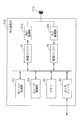
- FIG. 2 is a block diagram showing a functional configuration of the energy controller according to Embodiment 1 of the present invention.
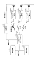
- FIG. 3 is a block diagram showing a functional configuration of the wireless communication IF of the energy controller according to Embodiment 1 of the present invention.
- FIG. 4 is a memory structure diagram of a home appliance characteristic table held by the energy controller according to Embodiment 1 of the present invention.
- FIG. 5 is a memory structure diagram of a power management table held by the energy controller according to Embodiment 1 of the present invention.
- FIG. 6 is a block diagram showing a functional configuration of the power saving control unit of the energy controller according to Embodiment 1 of the present invention.
- FIG. 1 is a diagram showing a network configuration according to Embodiment 1 of the present invention.
- FIG. 2 is a block diagram showing a functional configuration of the energy controller according to Embodiment 1 of the present invention
- FIG. 7 is a block diagram showing a functional configuration of the peak suppression unit of the energy controller according to Embodiment 1 of the present invention.
- FIG. 8 is a memory structure diagram of the power visualization table held by the peak suppression unit of the energy controller according to Embodiment 1 of the present invention.
- FIG. 9 is a block diagram showing a functional configuration of the network home appliance according to Embodiment 1 of the present invention.
- FIG. 10 is a block diagram showing a functional configuration of the wireless communication IF of the network home appliance according to Embodiment 1 of the present invention.
- FIG. 11 is a flowchart showing the operation of the power saving control unit of the energy controller according to Embodiment 1 of the present invention.
- FIG. 12 is a diagram showing an example of a correspondence relationship between total power consumption and time in the first embodiment of the present invention.
- FIG. 13 is a flowchart showing the operation of the peak suppression unit of the energy controller according to Embodiment 1 of the present invention.
- FIG. 14 is a memory structure diagram of another power management table held by the energy controller according to Embodiment 1 of the present invention.
- FIG. 15 is a block diagram showing a functional configuration of the energy controller according to Embodiment 2 of the present invention.
- FIG. 16 is a block diagram illustrating a functional configuration of the power saving control unit of the energy controller according to Embodiment 2 of the present invention.
- FIG. 17 is a memory structure diagram of a beacon table held by the power saving control unit of the energy controller according to Embodiment 2 of the present invention.
- FIG. 18 is a flowchart showing the operation of the power saving control unit of the energy controller according to Embodiment 2 of the present invention.
- FIG. 19 is a block diagram showing a functional configuration of the energy controller according to Embodiment 3 of the present invention.
- FIG. 20 is a block diagram illustrating a functional configuration of the power saving control unit of the energy controller according to Embodiment 3 of the present invention.
- FIG. 21 is a memory structure diagram of an application allowable delay table held by the power saving control unit of the energy controller according to Embodiment 3 of the present invention.
- FIG. 22 is a flowchart showing the operation of the power saving control unit of the energy controller according to Embodiment 3 of the present invention.
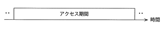
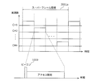
- FIG. 23 is a diagram showing the relationship between the access period and time in the fourth embodiment of the present invention.
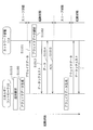
- FIG. 24 is a sequence diagram in which the energy controller according to Embodiment 4 of the present invention transmits awake data to network home appliances and transmits the data.
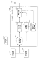
- FIG. 25 is a block diagram showing a functional configuration of the energy controller according to Embodiment 4 of the present invention.
- FIG. 26 is a block diagram illustrating a functional configuration of the wireless communication IF of the energy controller according to Embodiment 4 of the present invention.
- FIG. 27 is a block diagram illustrating a functional configuration of the power saving control unit of the energy controller according to Embodiment 4 of the present invention.
- FIG. 28 is a block diagram showing a functional configuration of a network home appliance according to Embodiment 4 of the present invention.
- FIG. 29 is a flowchart showing the operation of the power saving control unit of the energy controller according to Embodiment 4 of the present invention.
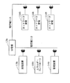
- FIG. 30 is a diagram showing a network configuration in the fifth embodiment of the present invention.
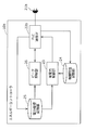
- FIG. 31 is a block diagram showing a functional configuration of the energy controller according to Embodiment 5 of the present invention.
- FIG. 32 is a block diagram showing a functional configuration of the PLC communication IF of the energy controller according to Embodiment 5 of the present invention.
- FIG. 33 is a block diagram showing a functional configuration of the network home appliance in the fifth embodiment of the present invention.
- FIG. 34 is a block diagram showing a functional configuration of the PLC communication IF of the network home appliance in the fifth embodiment of the present invention.
- FIG. 35 is a diagram showing a network configuration in the sixth embodiment of the present invention.
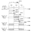
- FIG. 36 is a diagram illustrating a correspondence relationship between the frequency channel and time of the energy controller according to Embodiment 6 of the present invention.
- FIG. 37 is a diagram illustrating a correspondence relationship between the energy controller, the frequency channel of the network home appliance, and time in the sixth embodiment of the present invention.
- FIG. 38 is a block diagram showing a functional configuration of the energy controller according to Embodiment 6 of the present invention.
- FIG. 39 is a block diagram showing a functional configuration of the wireless communication IF of the energy controller according to Embodiment 6 of the present invention.
- FIG. 40 is a block diagram illustrating a functional configuration of the power saving control unit of the energy controller according to Embodiment 6 of the present invention.
- FIG. 41 is a flowchart showing the operation of the power saving control unit of the energy controller according to Embodiment 6 of the present invention.
- FIG. 42 is a block diagram showing a functional configuration of the energy controller according to a modification of the embodiment of the present invention.
- FIG. 43 is a diagram illustrating an example of a conventional wireless network configuration.
- FIG. 44 is a diagram showing a relationship between a conventional beacon period, an active period, and an inactive period.
- FIG. 45 is a flowchart showing an example of a sequence in which a conventional control station transmits data to a terminal device.
- FIG. 46 is a diagram illustrating an example of a network configuration for realizing an in-home EMS application.
- FIG. 47A is a diagram illustrating an example of a correspondence relationship between total power consumption and time.
- FIG. 47B is a diagram illustrating an example of a correspondence relationship between total power consumption and time.
- FIG. 1 is a diagram showing an example of a network configuration according to Embodiment 1 of the present invention.
- the energy controller 10 is connected to network home appliances 11 a, 11 b, and 11 c by radio 230.
- the energy controller 10 is included in the “communication device” described in the claims, and the network home appliances 11a, 11b, and 11c are included in the “communication terminal device” described in the claims.
- the wireless 230 is connected in accordance with IEEE 802.15.4 standard, IEEE 802.11 standard, ARIB (Association of Radio Industries and Businesses) compliant specific low power radio.
- IEEE 802.15.4 standard IEEE 802.11 standard
- ARIB Association of Radio Industries and Businesses
- the distribution board 12 supplies power to all home appliances (for example, network home appliances 11a, etc.) via the power line 210, and can measure the total power consumption in the home.
- the distribution board 12 is connected to the energy controller 10 via a wire 220, but the distribution board 12 may be connected to the energy controller 10 via a radio 230.
- the power generation device 13 and the power storage device 14 are connected to the energy controller 10 via a wire 220.
- the cable 220 has, for example, a connection such as Ethernet (registered trademark) or USB (Universal Serial Bus).
- Ethernet registered trademark
- USB Universal Serial Bus
- the power generation device 13 represents, for example, a device that generates power by using photovoltaic power generation, wind power generation, or a fuel cell.
- the power storage device 14 is, for example, a secondary battery such as a lithium ion battery. It is possible to store surplus power generated by the power generation device 13 in the power storage device 14. In the future, in the present invention, a general term for electric power generated by the power generation device 13 and accumulated by the power storage device 14 will be referred to as private power generation. This is different from the power purchased from the commercial power grid of the power company.
- the network home appliances 11a, 11b, and 11c are wireless terminal devices that repeat an activation state in which communication is possible and a sleep state in which communication is not possible.
- the network home appliances are three network home appliances 11a, 11b, and 11c, the number of network home appliances is not limited to three and may be any number.
- the energy controller 10 transmits a beacon signal that is a signal for establishing data transmission / reception to the network home appliances 11a, 11b, and 11c.
- the data is transmitted and received between 11b and 11c.
- the energy controller 10 can grasp the total power consumption from the distribution board 12, the power generation amount from the power generation device 13, and the power storage amount from the power storage device 14 via the wire 220. It is.
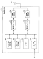
- FIG. 2 is a block diagram showing an example of a functional configuration of the energy controller 10 according to Embodiment 1 of the present invention.
- the antenna 21 is an antenna that performs wireless communication.
- the energy controller 10 includes a wireless communication IF 22, a power saving control unit 23, a device characteristic storage unit 24, a power management storage unit 25, and a peak suppression unit 26.
- the wireless communication IF 22 sends a beacon signal including information indicating the transmission cycle of the beacon signal to the network home appliances 11a, 11b, 11c, in order to activate the network home appliances 11a, 11b, and 11c at a cycle corresponding to the transmission cycle of the beacon signal.
- the wireless communication IF 22 has a data modulation and demodulation function, a media access control function, a frame generation function, and the like.
- the wireless communication IF 22 there is a function of a physical layer (Physical Layer) and a MAC layer (Media Access Control Layer) compliant with the IEEE 802.15.4 standard. Details of the wireless communication IF 22 will be described later with reference to FIG. The wireless communication IF 22 is included in the “communication interface unit” recited in the claims.
- the peak suppression unit 26 has a function of performing control such as peak cut and a function of inquiring and collecting the power consumption of each network home appliance in order from each network home appliance (polling). Details of the peak suppression unit 26 will be described later with reference to FIG.
- the device characteristic storage unit 24 is a memory that stores a home appliance characteristic table 24a.
- the home appliance characteristic table 24a is a table that holds power characteristics such as the rate of change of the power consumption value of each network home appliance that is currently connected. Details of the home appliance characteristic table 24a will be described later with reference to FIG.
- the power management storage unit 25 is a memory that stores a power management table 25a.
- the power management table 25a is a table including information such as the generated power value of the power generation device 13, the accumulated power value of the power storage device 14, and the total power consumption value of the power consuming devices, and the information is grasped and updated in real time. Details of the power management table 25a will be described later with reference to FIG.
- the power saving control unit 23 has a function for realizing power saving. Specifically, the power saving control unit 23 has a function of changing a beacon period by calculating a beacon period that is a transmission period for transmitting a beacon signal based on information in the home appliance characteristic table 24a and the power management table 25a. .
- the power saving control unit 23 has a differential power value that is a value obtained by subtracting the total power consumption value of the power consuming devices from the suppliable power value to the power consuming devices including the network home appliances 11a, 11b, and 11c.
- the beacon period is determined so that the larger the value, the longer the beacon period. Details of the power saving control unit 23 will be described later with reference to FIG.
- FIG. 3 is a block diagram showing a detailed functional configuration of the wireless communication IF 22 shown in FIG. 3, the same components as those in FIG. 2 are denoted by the same reference numerals, and description thereof is omitted.
- the wireless communication IF 22 includes a wireless transmission unit 31, a wireless reception unit 32, a beacon generation unit 33, a sleep management unit 34, a memory 35, an interface 36, a transmission buffer 37, and a reception buffer 38.
- the transmission buffer 37 has a function of temporarily buffering data before transmission such as a beacon signal.
- the wireless transmission unit 31 has a function of extracting data such as a beacon signal from the transmission buffer 37, modulating the data signal, and transmitting data such as a beacon signal at an appropriate timing by media access control.
- the reception buffer 38 has a function of temporarily buffering data after reception.
- the wireless reception unit 32 has a function of demodulating the received data signal and transferring the data to the reception buffer 38.
- the memory 35 stores information such as a beacon period, an active period, and an inactive period.
- the beacon signal transmitted by the wireless transmission unit 31 includes information such as a beacon period, an active period, and an inactive period stored in the memory 35.
- the beacon generator 33 has a function of generating a beacon frame. Specifically, the beacon generation unit 33 generates a beacon frame that is a beacon signal based on the beacon period time stored in the memory 35 and stores the beacon frame in the transmission buffer 37.
- the sleep management unit 34 has a function of discriminating a sleep state according to information such as an inactive period stored in the memory 35 and managing whether to set the wireless communication IF 22 to a sleep state or an activation state. Have.
- the interface 36 has a function of connecting the wireless communication IF 22 to the peak suppressing unit 26, the power saving control unit 23, and the device characteristic storage unit 24.
- FIG. 4 is a diagram showing an example of the memory structure of the home appliance characteristic table 24a shown in FIG.
- Information such as “product name (model number)”, “device address”, “maximum power consumption (W)”, and “maximum change rate (W / sec)” is stored in the home appliance characteristic table 24a.
- the product name (model number) indicates the type and product number of network home appliances that are home appliances.
- the device address is a unique ID that uniquely identifies each home appliance. For example, there are a MAC address and a 16-bit short address defined in IEEE802.15.4.
- Maximum power consumption indicates the maximum power consumption of each home appliance.
- the maximum rate of change indicates the rate of change in power consumption of each home appliance.
- the above information is added each time a home appliance is connected to the energy controller 10.
- the home appliance characteristic table 24a can be held in advance by the energy controller 10, or can be created and updated while learning the power consumption and the rate of change of each home appliance.
- FIG. 5 is a diagram showing an example of the memory structure of the power management table 25a shown in FIG.
- the power management table 25a stores information such as “date”, “time”, “in-house power supply capacity value”, “total power consumption value”, and the like.
- the date and time indicate the date and time when the power management table 25a is updated. It is assumed that the power management table 25a is periodically updated and an updated value is added.
- the generated power value of the private power supply capability value is information on the power generated by the power generator 13.
- the stored power value of the private power supply capability value is power information stored in the power storage device 14.
- the private power generation supply capacity is electric power other than that purchased from the commercial power grid of the electric power company, is electric power generated at home or in the vicinity thereof, and indicates the amount of electric power that can be used at present.
- the total power consumption value is information obtained from the distribution board 12 and is the total power consumed by a plurality of devices such as home appliances simultaneously used.
- FIG. 14 is a diagram illustrating an example of a memory structure of a power management table 25b, which is another example of the power management table.
- the power management table 25b stores information such as “date”, “time”, “electricity rate fluctuation boundary value”, “distribution panel supply capacity value”, and “total power consumption value”.
- the date and time indicate the date and time when the power management table 25b is updated. It is assumed that the power management table 25b is periodically updated and an updated value is added.
- the distribution board supply capacity value is a limit value at which the breaker of the distribution board 12 cuts off the power supply. That is, the distribution board supply capacity value is a value indicating the power value that can be supplied by the distribution board 12.
- the electricity price fluctuation boundary value is a boundary value at which the electricity price per unit amount changes. That is, the electricity price fluctuation boundary value is a contract power value with a power company at the boundary where the electricity price increases.
- the total power consumption value is the total power consumption value of the power consuming device, similarly to the power management table 25a of FIG.
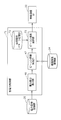
- FIG. 6 is a block diagram showing a detailed functional configuration of the power saving control unit 23 shown in FIG.
- the power saving control unit 23 includes a power difference calculation unit 46 and a beacon period calculation unit 47.
- the power difference calculation unit 46 can supply the latest private power generation supply capability value (the generated power value of the power generation device 13 + the accumulated power value of the power storage device 14) as a suppliable power value from the power management table 25a shown in FIG. It has a function of acquiring a power value and a total power consumption value and calculating a differential power value obtained by subtracting the total power consumption value from the suppliable power value.
- the private power supply capacity value is 5000 W (3010 W + 1990 W) and the total power consumption value is 200 W, so the differential power value is 4800 W. This means that the remaining 4800 W can be used up to the private power generation supply capacity value. If it exceeds 4800W, it will be necessary to buy electric power from an electric power company. That is, the differential power value means power that can be used in private power generation in the future.
- the power difference calculation unit 46 acquires the electricity price fluctuation boundary value and the total power consumption value, and calculates the total power consumption value from the electricity price fluctuation boundary value. It is also possible to calculate a difference power value obtained by subtracting.
- This differential power value means the power that can be used before the electricity price fluctuates in the future.
- the power difference calculation unit 46 acquires the distribution board supply capability value and the total power consumption value, and supplies the distribution board. It is also possible to calculate a differential power value obtained by subtracting the total power consumption value from the capability value. This differential power value means the power that can be supplied by the distribution board 12 in the future, and exceeding this will cause the electric breaker (breaker) to fall.
- the beacon period calculation unit 47 is a value obtained by using the change rate of the total power consumption value calculated based on the change rate of the power consumption value of the power consuming device, and subtracts the total power consumption value from the suppliable power value. It has a function of calculating a value obtained by dividing the difference power value as a beacon period.
- the beacon period calculation unit 47 uses the maximum change rate among the power consumption values of all the power consumption devices as the change rate of the total power consumption value, and calculates the difference power value as shown in FIG.
- the beacon period is calculated by dividing by the maximum rate of change of the characteristic table 24a. That is, the maximum change rate of the home appliance characteristic table 24a is selected from among the stored home appliances.
- beacon calculation method is as follows.
- the beacon period calculation unit 47 stores the calculated beacon period in the memory 35 of the wireless communication IF 22. As described above, it is possible to dynamically change the beacon period of the wireless network.
- the time of the calculated beacon period is a time when there is another beacon transmission opportunity until the remaining differential power value considering the power change rate is used up.
- the rate of change of the total power consumption value not only the maximum value of the maximum rate of change in the home appliance characteristic table 24a but also the sum of the maximum rate of change from the maximum value to two units can be used.
- FIG. 7 is a block diagram showing a detailed functional configuration of the peak suppression unit 26 shown in FIG.
- the peak suppression unit 26 includes a visualization control unit 51, a power visualization storage unit 52, a threshold monitoring unit 53, and a peak cut control unit 54.
- the visualization control unit 51 has a function of inquiring and acquiring power consumption information of each device of the network home appliances 11a to 11c connected to the energy controller 10. As an inquiry method, the visualization control unit 51 makes a power consumption inquiry to the network home appliance and receives a response of the power consumption information from the network home appliance. There is a polling method in which this is sequentially performed on the connected network home appliances 11a to 11c.
- the power visualization storage unit 52 is a storage unit that stores a power visualization table 52 a including power consumption for each network home appliance acquired by the visualization control unit 51. Details of the power visualization table 52a will be described later with reference to FIG.
- the threshold monitoring unit 53 has a function of acquiring the total power consumption value from the power management table 25a and monitoring whether or not the total power consumption value reaches the designated peak suppression threshold. When the total power consumption value exceeds the peak suppression threshold, peak cut is executed.
- the peak cut control unit 54 has a function of performing peak cut. Peak cut is the total power consumption by, for example, turning off the power of household appliances such as lighting and television, changing the set temperature of the air conditioner, changing the high wind mode of the air conditioner to the power saving mode, reducing the illumination intensity of the lighting, etc. The purpose is to suppress.
- the peak cut control unit 54 refers to the power visualization table 52a to select and execute a device that performs peak suppression.
- FIG. 8 is a diagram showing an example of the memory structure of the power visualization table 52a shown in FIG.
- the power visualization table 52a stores information such as “product name (model number)”, “device address”, “current power consumption (W)”, and “peak suppression information”.
- the product name (model number) and device address are the same as the product name (model number) and device address of the home appliance characteristic table 24a shown in FIG.
- the current power consumption is the power consumption of each network home appliance collected by the visualization control unit 51 by polling.
- the peak suppression information includes whether or not peak suppression is possible and the type of peak suppression.
- “Availability” of peak suppression means a device capable of peak suppression
- “Absence” of peak suppression means a device that cannot suppress a peak.
- the type of peak suppression means for performing peak suppression.
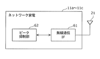
- FIG. 9 is a block diagram illustrating an example of a functional configuration of the network home appliances 11a, 11b, and 11c according to Embodiment 1 of the present invention. 9, the same components as those in FIG. 2 are denoted by the same reference numerals, and description thereof is omitted.
- each of the network home appliances 11a, 11b, and 11c includes a wireless communication IF 61 and a peak suppression unit 62.
- the wireless communication IF 61 has data modulation and demodulation functions, media access control functions, frame generation functions, and the like.
- the wireless communication IF 61 there is a function of a physical layer (Physical Layer) and a MAC layer (Media Access Control Layer) of IEEE 802.15.4. Details of the wireless communication IF 61 will be described later with reference to FIG.
- the peak suppression unit 62 has a function of returning the current power consumption in response to an inquiry request for power consumption information by the visualization control unit 51 of the energy controller 10. Further, the peak suppression unit 62 has a function of executing a peak cut operation such as turning off the power or changing the room temperature in accordance with a peak cut execution command from the peak cut control unit 54 of the energy controller 10.
- FIG. 10 is a block diagram showing a detailed functional configuration of the wireless communication IF 61 in FIG. In FIG. 10, the same components as those of the wireless communication IF 22 shown in FIG.
- the wireless communication IF 61 includes a wireless transmission unit 31, a wireless reception unit 32, a memory 35, an interface 36, a transmission buffer 37, and a reception buffer 38, which are the same components as the components included in the wireless communication IF 22.
- a beacon analysis unit 65 and a sleep management unit 66 are provided.
- the beacon analysis unit 65 has a function of receiving and analyzing a beacon frame transmitted from the energy controller 10. Specifically, the beacon analysis unit 65 analyzes the presence / absence of Data Pending indicated in the beacon frame. The beacon analysis unit 65 generates a data request frame and transmits it to the energy controller 10 when Pending Data addressed to the own station is included.
- the sleep management unit 66 checks the length of the active period and the transmission time of the next beacon frame from the beacon frame analysis result of the beacon analysis unit 65, and manages the sleep state and the activation state.
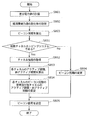
- FIG. 11 is a flowchart showing the operation of the beacon period changing method by the power saving control unit 23 according to Embodiment 1 of the present invention.
- the power difference calculation unit 46 of the power saving control unit 23 calculates a difference power value between a power value that can be supplied to the power consuming device and the total power consumption value of the power consuming device ( S801).
- the beacon period calculation unit 47 acquires the maximum value of the maximum change rate as the change rate of the total power consumption value of the power consuming device from the home appliance characteristic table 24a (S802).
- the beacon period calculation unit 47 calculates the beacon period by dividing the difference power value by the maximum value of the maximum change rate based on the above formula 1 (S803).
- the beacon period calculating unit 47 changes the beacon period by setting and updating the calculated beacon period in the memory 35 of the wireless communication IF 22 (S804).
- the power saving control unit 23 sets the beacon period so that the beacon period becomes longer as the difference power value between the power supplyable power value to the power consumption apparatus and the total power consumption value of the power consumption apparatus increases. To decide.
- the wireless communication IF 22 transmits a beacon signal including information indicating the beacon period to the network home appliances 11a to 11c (S805).
- the network home appliances 11a to 11c switch between the sleep state and the activation state so that they are in the activation state when the next beacon signal is received.
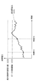
- FIG. 12 is a diagram showing an example of temporal variation of the total power consumption 1031 in the home in Embodiment 1 of the present invention.
- the maximum usable power value 1032 shown in the figure is, for example, the allowable amount of distribution board breakers (distribution panel supply capacity value), the supply amount from the electric power company, the electricity price fluctuation boundary value, the solar power generation device, the wind power generation And the amount of private power generation by the fuel cell device.
- the maximum usable power value 1032 is the private power generation supply amount.
- the peak suppression threshold 1033 is a threshold that is set to a value smaller than the maximum usable power value 1032 and is monitored by the threshold monitoring unit 53 of the peak suppression unit 26. When the total power consumption 1031 exceeds the peak suppression threshold 1033, peak control works and the total power consumption 1031 decreases.
- time T3 and time T4 are compared.
- the total power consumption 1031 at time T3 is lower than the total power consumption 1031 at time T4. That is, the difference power value is larger at time T3 than at time T4. For this reason, according to the change method of the beacon period of Embodiment 1 of this invention, the beacon period in time T3 becomes longer than the beacon period in time T4.
- the beacon cycle is set to be short, that is, the sleep time is set to be short, so that the peak suppression request can be responded instantaneously.
- FIG. 13 is a flowchart showing an operation of peak suppression by the peak suppression unit 26 in Embodiment 1 of the present invention.
- the threshold monitoring unit 53 compares and monitors the total power consumption 1031 and the peak suppression threshold 1033 (S806).
- the peak cut control unit 54 refers to the power visualization table 52a to check whether there is a device capable of peak suppression (S807). If the total power consumption 1031 does not exceed the peak suppression threshold 1033 (No in S806), the threshold monitoring unit 53 again monitors the total power consumption 1031 and the peak suppression threshold 1033 (S806).
- the peak cut control unit 54 selects a household appliance to be peak-suppressed and its type (S808). If there is no device capable of peak suppression (No in S807), the threshold monitoring unit 53 again compares and monitors the total power consumption 1031 and the peak suppression threshold 1033 (S806).
- the peak cut control unit 54 remotely controls the home appliance to execute the peak cut (S809).
- the beacon period is calculated in consideration of the rate of change characteristic of the power consumption of the connected home appliances and the difference power value between the private power supply amount and the total power consumption.
- the energy controller 10 Normally, it is necessary for the energy controller 10 to transmit a peak cut execution control command to the network home appliances 11a to 11c before the differential power value is used up.
- the energy controller 10 needs to transmit a beacon to which data pending is added. That is, as in the first embodiment, calculating the beacon period in consideration of the difference power value and the rate of change in power consumption of the home appliance means that for the energy controller 10, the beacon transmission period before the difference power value is used up. Means that will definitely come. Thus, the beacon period is set so that there is no delay in peak cut command control. Further, when the difference power value is large, the beacon cycle is set to be long, so that low power consumption can be realized.
- the energy controller 10 includes a beacon signal including information indicating a beacon period that is determined to be longer as the difference power value between the suppliable power value to the power consuming device and the total power consumption value of the power consuming device is larger.
- the beacon period is calculated based on the remaining usable power information.
- peak suppression for controlling the total power consumption value so as not to exceed the suppliable power value is controlled without delay, and the beacon period is set to be long when the differential power value is large.
- wireless terminal apparatus can maintain a sleep state for a long time.
- the energy controller 10 determines the beacon period so that the beacon period becomes longer as the difference power value obtained by subtracting the total power consumption value from the sum of the generated power value and the accumulated power value is larger.
- the power value obtained by subtracting the total power consumption from the power generated and stored at home or in the area that is, the remaining power information that can be used for self-power generation and self-storage without purchasing power from the commercial power system of the power company.
- a beacon period is calculated.
- peak suppression for controlling the total power consumption value so that it does not exceed the sum of the current generated power value and the stored power value is controlled without delay.
- the beacon period is set to be long.
- the energy controller 10 determines the beacon period so that the beacon period becomes longer as the difference power value obtained by subtracting the total power consumption value from the electricity rate fluctuation boundary value is larger. That is, the beacon period is calculated based on the power value obtained by subtracting the total power consumption from the power information of the contracted electricity price fluctuation boundary value of the power company, that is, the power information available with the current contracted electricity price. As a result, peak suppression for controlling the total power consumption value so as not to exceed the current contracted electricity bill boundary value is controlled without delay, and the beacon period is set to be long when the differential power value is large.
- the energy controller 10 as the control station determines the beacon period so that the beacon period becomes longer as the difference power value obtained by subtracting the total power consumption value from the distribution board supply capacity value is larger. That is, based on the power supply power of the distribution board, for example, the power value obtained by subtracting the total power consumption from the limit value of the breaker (breaker) of the distribution board, that is, the current power information that can be supplied by the distribution board, Calculate the beacon period. As a result, peak suppression that controls the total power consumption value so that it does not exceed the current distribution board supply capacity limit value is executed without delay, and if the differential power value is large, the beacon period is set to be long. Is done.
- the energy controller 10 determines the beacon period by calculating a value obtained by dividing the difference power value by the change rate of the total power consumption value calculated based on the change rate of the power consumption value as the beacon period. Thereby, the beacon period can be accurately calculated so that the total power consumption value does not exceed the suppliable power value.
- the energy controller 10 according to the first embodiment, it is possible to achieve both low power consumption and real-time performance of the wireless terminal device even in applications such as peak suppression without data regularity. Can do.
- the beacon period is controlled by calculating the beacon period from the difference power value between the suppliable power value and the total power consumption value and the power consumption change rate characteristic of the home appliance.
- the beacon period is determined by comparing with the beacon value of the stored beacon table.
- the beacon period can be dynamically changed in a system in which the beacon period is determined in several patterns as in IEEE 802.15.4.
- the network configuration in the second embodiment is the same as the network configuration in FIG. 1 of the first embodiment, and a description thereof is omitted here.
- FIG. 15 is a block diagram showing an example of a functional configuration of the energy controller 10 according to Embodiment 2 of the present invention. Components having the same functions as those of the blocks of the energy controller 10 according to the first embodiment described in FIG. 2 are given the same numbers, and description thereof is omitted here.
- the energy controller 10 includes a wireless communication IF 22, a device characteristic storage unit 24, and a power management storage unit 25 that are the same components as the components included in the energy controller 10 according to the first embodiment.
- a power saving control unit 71 is provided in addition to the peak suppression unit 26, a power saving control unit 71 is provided.
- the power saving control unit 71 has a function for realizing power saving. Specifically, the power saving control unit 71 includes the home appliance characteristic table 24a stored in the device characteristic storage unit 24, the power management table 25a stored in the power management storage unit 25, and the power saving control unit 71 in the memory. Based on the information stored in the beacon table 72a, it has a function of calculating a beacon period and changing the beacon period.
- FIG. 16 is a block diagram showing a detailed functional configuration of the power saving control unit 71 shown in FIG. Components having the same functions as those of the blocks included in the power saving control unit 23 described in FIG. 6 are assigned the same numbers, and description thereof is omitted here.
- the power saving control unit 71 includes a transmission cycle pattern storage unit 72 in addition to the power difference calculation unit 46 and the beacon cycle calculation unit 47 that are the same components as the components included in the power saving control unit 23. And a beacon period selector 73.
- the transmission cycle pattern storage unit 72 stores a beacon table 72a including beacon cycle patterns that can be set in the wireless network system.
- FIG. 17 is a diagram illustrating an example of a memory structure of the beacon table 72a.
- the beacon table 72a is an example of holding eight types of beacon periods.
- the beacon period selection unit 73 has a function of selecting a beacon period by comparing the beacon period calculated by the beacon period calculation unit 47 with the beacon pattern of the beacon table 72a.
- the beacon period calculation unit 47 calculates a beacon period such that the beacon period becomes longer as the difference power value between the suppliable power value and the total power consumption value is larger.
- the beacon period selecting unit 73 selects a beacon period
- the beacon period 6 sec is calculated by the beacon period calculating unit 47 as in the example of the first embodiment
- the beacon period selection unit 73 stores the selected beacon period in the memory 35 of the wireless communication IF 22. As described above, it is possible to dynamically change the beacon period of the wireless network among the determined types.
- the power saving control unit 71 calculates the beacon period such that the beacon period becomes longer as the difference power value is larger. From the beacon pattern, the power saving control unit 71 is within the calculated beacon period and in the beacon pattern. Select the longest beacon period.
- FIG. 18 is a flowchart showing the operation of the beacon cycle changing method by the power saving control unit 71 according to Embodiment 2 of the present invention.
- the processes from S801 to S803 and S804 to S805 in FIG. 18 are the same as the processes from S801 to S803 and S804 to S805 described in FIG. Is omitted.
- the power difference calculation unit 46 of the power saving control unit 71 calculates the difference power value between the suppliable power value and the total power consumption value (S801). Thereafter, the beacon period calculation unit 47 acquires the maximum value of the maximum change rate as the change rate of the total power consumption value of the power consuming equipment from the home appliance characteristic table 24a (S802). Thereafter, the beacon period calculation unit 47 calculates a beacon period based on the above formula 1 (S803).
- the beacon cycle selecting unit 73 refers to the beacon table 72a (S811), and selects a value that is shorter than the beacon cycle calculated by the beacon cycle calculating unit 47 and has the longest beacon cycle from the beacon patterns of the beacon table 72a. Select (S812).
- the beacon cycle selection unit 73 changes the beacon cycle by updating the selected beacon cycle in the memory 35 of the wireless communication IF 22 (S804). Thereafter, based on the beacon period, the wireless communication IF 22 transmits a beacon signal including information indicating the beacon period to the network home appliances 11a to 11c (S805).
- the second embodiment taking into account the rate of change characteristic of the power consumption of connected home appliances and the difference power value between the suppliable power value and the total power consumption value, the larger the difference power value, the longer.
- a beacon period is calculated. Furthermore, when a beacon period pattern is defined in the wireless network system, the calculated beacon period is compared with the determined beacon period pattern, and the calculated beacon period is equal to or less than the calculated beacon period. The longest beacon period in the pattern is selected. As a result, even in a wireless network system in which several types of beacon periods are defined as in the IEEE 802.15.4 standard, when the differential power value is large, the beacon period is set to be long, and low power consumption can be realized. When the power value is small, the beacon period is set short, and it becomes possible to immediately respond to a request for peak suppression.
- the beacon period is calculated by calculating the beacon period based on the difference power value between the suppliable power value and the total power consumption value and the power consumption change rate characteristic of the home appliance.
- Embodiment 3 after calculating the beacon period, the allowable delay time of the application used in the wireless network system is compared to determine the beacon period. As a result, setting the beacon period beyond the allowable delay time of the application can be prevented, and the allowable time of the application can be satisfied.
- the network configuration in the third embodiment is the same as the network configuration in FIG. 1 of the first embodiment, and a description thereof is omitted here.
- FIG. 19 is a block diagram showing an example of a functional configuration of the energy controller 10 according to Embodiment 3 of the present invention. Components having the same functions as those of the blocks of the energy controller 10 according to the first embodiment described in FIG. 2 are given the same numbers, and description thereof is omitted here.
- the energy controller 10 includes a wireless communication IF 22, a device characteristic storage unit 24, and a power management storage unit 25 that are the same components as the components included in the energy controller 10 according to the first embodiment.
- a power saving control unit 81 is provided in addition to the peak suppression unit 26, a power saving control unit 81 is provided.
- the power saving control unit 81 has a function for realizing power saving. Specifically, the power saving control unit 81 includes the home appliance characteristic table 24a stored in the device characteristic storage unit 24, the power management table 25a stored in the power management storage unit 25, and the power saving control unit 81 in the memory. Based on the information stored in the application allowable delay table 82a, the beacon period is calculated and the beacon period is changed.
- FIG. 20 is a block diagram showing a detailed functional mechanism of the power saving control unit 81 shown in FIG. Components having the same functions as those of the blocks included in the power saving control unit 23 described in FIG. 6 are assigned the same numbers, and description thereof is omitted here.
- the power saving control unit 81 includes an application allowable delay storage unit 82 in addition to the power difference calculation unit 46 and the beacon period calculation unit 47 that are the same components as the components included in the power saving control unit 23. And a beacon period comparison unit 83.
- the application allowable delay storage unit 82 stores an application allowable delay table 82a including the allowable delay times of a plurality of applications used in the wireless network system. That is, the application allowable delay table 82a stores an allowable delay time that is an allowable delay time when executing a predetermined application.
- FIG. 21 is a diagram illustrating an example of a memory structure of the application allowable delay table 82a.
- FIG. 21 shows an example in which the allowable delay times of two types of applications “visualization of power consumption” and “peak suppression” are held.
- the allowable delay time for visualizing power consumption is 5000 msec, and the allowable delay time for peak suppression is 500 msec.
- the beacon period comparison unit 83 has a function of determining the beacon period by comparing the beacon period calculated by the beacon period calculation unit 47 with the allowable delay time of the application allowable delay table 82a.
- the beacon period calculation unit 47 calculates a beacon period such that the beacon period becomes longer as the difference power value between the suppliable power value and the total power consumption value is larger.
- the beacon period comparison unit 83 determines the beacon period
- the allowable delay time for peak suppression is 500 msec, which is the shortest.
- the beacon period calculation unit 47 calculates a beacon period of 6 sec
- the calculated beacon period (6 sec) is compared with an allowable delay time of 500 msec for peak suppression, and the shorter one is calculated. 500 msec is determined as the beacon period.
- the beacon period comparison unit 83 stores the determined beacon period in the memory 35 of the wireless communication IF 22. As described above, the beacon period is determined within a range that satisfies the allowable delay time of a plurality of applications in the wireless network, and the beacon period is dynamically changed.
- the power saving control unit 81 calculates the beacon period such that the beacon period becomes longer as the difference power value is larger, and the calculated beacon period is the allowable delay stored in the application allowable delay storage unit 82. If it is longer than the shortest allowable delay time, the shortest allowable delay time is determined as the beacon period. If the calculated beacon period is equal to or shorter than the shortest allowable delay time, the calculated beacon The period is determined as a beacon period to be transmitted by being included in the beacon signal.
- FIG. 22 is a flowchart showing the operation of the beacon period changing method by the power saving control unit 81 according to Embodiment 3 of the present invention.
- the processes from S801 to S803 and S804 to S805 in FIG. 22 are the same as the processes from S801 to S803 and S804 to S805 described in FIG. Is omitted.
- the power difference calculation unit 46 of the power saving control unit 81 calculates a difference power value between the suppliable power value and the total power consumption value (S801). Thereafter, the beacon period calculation unit 47 acquires the maximum value of the maximum change rate as the change rate of the total power consumption value of the power consuming equipment from the home appliance characteristic table 24a (S802). Thereafter, the beacon period calculation unit 47 calculates a beacon period based on the above formula 1 (S803).
- the beacon period comparison unit 83 acquires the shortest allowable delay time of the application from the application allowable delay table 82a (S815). Thereafter, the beacon period comparison unit 83 compares the shortest allowable delay time with the calculated beacon period calculated by the beacon period calculation unit 47 (S816).
- the beacon period comparison unit 83 determines that the calculated beacon period is shorter than the shortest allowable delay time (Yes in S816), the beacon period to be determined is set as the value of the calculated beacon period (S817).
- the beacon period comparison unit 83 determines that the shortest allowable delay time is shorter than the calculated beacon period (No in S816), the beacon period to be determined is set as the value of the shortest allowable delay time (S818).
- the beacon period comparison unit 83 updates the determined beacon period in the memory 35 of the wireless communication IF 22 to change the beacon period (S804). Thereafter, based on the beacon period, the wireless communication IF 22 transmits a beacon signal including information indicating the beacon period to the network home appliances 11a to 11c (S805).
- the difference power value increases as the difference power value increases.
- a beacon period is calculated.
- the allowable delay time required by the application of the wireless network system is compared with the calculated beacon period, and if the calculated beacon period is longer than the minimum allowable delay time among the allowable delay times, the shortest value Is determined as a beacon period.
- the beacon when the differential power value is large, the beacon is set so as to satisfy the allowable delay time of the application. The period is set, power consumption can be reduced, and when the difference power value is small, the beacon period is set short, and the request for peak suppression can be dealt with immediately.
- the beacon period is calculated by calculating the beacon period based on the difference power value between the suppliable power value and the total power consumption value and the power consumption change rate characteristic of the home appliance.
- the beacon period is determined by comparing with the beacon value in the beacon table to be held.
- the beacon period can be dynamically changed in a system in which the beacon period is determined in several patterns as in IEEE 802.15.4.
- the beacon period is determined by comparing the calculated beacon period with the allowable delay time of the application used in the wireless network system. As a result, setting the beacon period beyond the allowable delay time of the application can be prevented, and the allowable time of the application can be satisfied.
- the activation state and the sleep state of the radio control station and the wireless terminal device are set without using the beacon frame.
- the transmission cycle of the awake data is controlled.
- the awake data corresponds to an “awake signal” described in the claims.
- the transmission cycle of the awake data is set long, and low power consumption is achieved.
- the transmission period of the awake data is set to be short, and the request for peak suppression can be responded instantaneously.
- the network configuration in the fourth embodiment is the same as the network configuration in FIG. 1 of the first embodiment, and a description thereof is omitted here.
- a beacon frame is not used. For this reason, there is no concept of the active period 1007 and the non-active period 1008 as shown in FIG. 44, and as shown in FIG. 23, all times are access periods.
- the access period is a period in which the radio control station and the radio terminal device communicate with each other using access control such as CSMA.
- FIG. 23 is a diagram showing the relationship between the access period and time in the fourth embodiment of the present invention.
- FIG. 24 shows an example of a sequence in which the energy controller 10 having the function of the radio control station uses the awake data instead of the beacon frame in the fourth embodiment to perform data communication with the network home appliance 11a having the function of the radio terminal device. It is a flowchart which shows.
- the awake data includes time information until the next awake data transmission, and the wireless terminal device always receives this awake data.
- the same numbers are assigned to steps that perform the same processes as those shown in FIG.
- the energy controller 10 buffers the data.
- the energy controller 10 generates an awake frame (S1100) based on the time information until the next awake data transmission included in the previously transmitted awake data, and transmits the awake data (S1101).
- the network home appliance 11a changes from the sleep state to the activated state at the timing of receiving the awake data, and receives the awake data (S1101).
- the network home appliance 11a analyzes the awake data (S1102) and confirms the transmission time of the next awake data.
- the network home appliance 11a transmits a data request in order to check whether there is data buffered in the energy controller 10 (S1013).
- the energy controller 10 transmits the data to the network home appliance 11a (S1014).
- the network home appliance 11a returns an ACK that is an arrival confirmation signal to the energy controller 10 (S1015).
- the energy controller 10 Conversely, if the energy controller 10 receives the data request (S1013) and there is no buffer link data addressed to the network home appliance 11a, the energy controller 10 notifies the network home appliance 11a of an ACK to that effect.
- the network home appliance 11a changes from the sleep state to the activated state at the timing of receiving periodically transmitted awake data, inquires the energy controller 10 for the data, receives the data, and again receives the next awake.
- the sleep state is entered until the data reception timing.
- the network home appliance 11a immediately enters the sleep state until the next awake data reception timing. With such an operation, it is possible to reduce the power consumption of the network home appliance 11a.
- FIG. 25 is a block diagram showing an example of the functional configuration of the energy controller 10 according to Embodiment 4 of the present invention. Components having the same functions as those of the blocks of the energy controller 10 according to the first embodiment described in FIG. 2 are given the same numbers, and description thereof is omitted here.
- the energy controller 10 includes a device characteristic storage unit 24, a power management storage unit 25, and a peak suppression unit that are the same components as the components included in the energy controller 10 according to the first embodiment. 26, a power saving control unit 91 and a wireless communication IF 92 are provided.
- the wireless communication IF 92 transmits awake data including information indicating the transmission period of the awake data to the network home appliances 11a to 11c in order to activate the network home appliances 11a to 11c at a cycle corresponding to the transmission cycle of the beacon signal.
- the wireless communication IF 92 has functions such as data modulation and demodulation functions, media access control, and frame generation.
- the wireless communication IF 92 there is a function of a physical layer (Physical Layer) and a MAC layer (Media Access Control Layer) of IEEE 802.15.4. Details of the wireless communication IF 92 will be described later with reference to FIG. The wireless communication IF 92 is included in the “communication interface unit” recited in the claims.
- the power saving control unit 91 has a function for realizing power saving. Specifically, the power saving control unit 91 transmits awake data based on information in the home appliance characteristic table 24a stored in the device characteristic storage unit 24 and the power management table 25a stored in the power management storage unit 25. It has a function of calculating a period and generating awake data. Details of the power saving control unit 91 will be described later with reference to FIG.
- FIG. 26 is a block diagram showing a detailed functional configuration of the wireless communication IF 92 shown in FIG. 26, the same components as those in FIG. 3 are denoted by the same reference numerals, and description thereof is omitted.
- the difference between the components of the wireless communication IF 92 shown in FIG. 26 and the components of the wireless communication IF 22 shown in FIG. 3 is that the beacon generator 33 is not included in the wireless communication IF 92. is there.
- FIG. 27 is a block diagram showing a detailed functional configuration of the power saving control unit 91 shown in FIG. Components having the same functions as those of the blocks of the power saving control unit 23 described in FIG. 6 are assigned the same numbers, and description thereof is omitted here.
- the power saving control unit 91 includes an awake data generation unit 93 in addition to the power difference calculation unit 46 which is the same component as the component included in the power saving control unit 23.
- the awake data generation unit 93 divides the difference power value obtained by subtracting the total power consumption value from the supplyable power value by the change rate of the total power consumption value calculated based on the change rate of the power consumption value of the power consuming device. It has a function of calculating a value as a transmission period of awake data.
- the awake data generation unit 93 sets the maximum change rate among the power consumption values of all the power consumption devices as the change rate of the total power consumption value, and the difference power value acquired by the power difference calculation unit 46 And the transmission rate of the awake data is calculated based on the maximum change rate of the home appliance characteristic table 24a shown in FIG. That is, the maximum change rate of the home appliance characteristic table 24a is selected from among the stored home appliances.
- 800 W / sec of the microwave oven is the maximum maximum rate of change compared to other devices.
- the calculation method of the transmission period of the awake data is as follows.
- Awake data transmission cycle difference power value / rate of change (Formula 2)
- the awake data generation unit 93 stores the calculated awake data transmission cycle in the memory 35 of the wireless communication IF 92.
- the rate of change of the total power consumption value not only the maximum value of the maximum rate of change in the home appliance characteristic table 24a but also the sum of the maximum rate of change from the maximum value up to three units can be used.
- the awake data transmission cycle is 3428 msec ( ⁇ 4800 / 1400).
- FIG. 28 is a block diagram illustrating an example of a functional configuration of the network home appliances 11a, 11b, and 11c according to the fourth embodiment. 28, the same components as those in FIGS. 9 and 25 are denoted by the same reference numerals, and description thereof is omitted.
- each of the network home appliances 11a, 11b, and 11c in the fourth embodiment is a peak that is the same component as each of the network home appliances 11a, 11b, and 11c in the first embodiment.
- a wireless communication IF 92 and a power saving control unit 95 are provided. Note that the wireless communication IF 92 has the same function as the wireless communication IF 92 included in the energy controller 10 shown in FIG.
- the power saving control unit 95 has a function of analyzing the awake data, and recognizes a transmission time included in the awake data and next to transmit the awake data. Further, after receiving the awake data, the power saving control unit 95 controls the memory 35 of the wireless communication IF 92 and transmits a data request to the energy controller 10. When the power saving control unit 95 determines that there is no data transmission / reception with the energy controller 10, the power saving control unit 95 controls the sleep management unit 34 of the wireless communication IF 92 to transition to the sleep state, thereby realizing low power consumption. .
- FIG. 29 is a flowchart showing the operation of the method for changing the awake data transmission cycle by the power saving control unit 91 of the energy controller 10 according to the fourth embodiment of the present invention.
- the power difference calculation unit 46 of the power saving control unit 91 calculates a difference power value between a power value that can be supplied to the power consuming device and the total power consumption value of the power consuming device ( S801).
- the awake data generation unit 93 acquires the maximum value of the maximum change rate as the change rate of the total power consumption value of the power consuming device from the home appliance characteristic table 24a (S820).
- the awake data generation unit 93 calculates the awake data transmission cycle by dividing the differential power value by the maximum value of the maximum change rate based on the equation 2 (S821).
- the awake data generation unit 93 generates awake data based on the calculated awake data transmission cycle, and transmits the awake data (S822).
- the power saving control unit 91 increases the difference power value between the suppliable power value to the power consuming device and the total power consumption value of the power consuming device so that the awake data transmission cycle becomes longer. Determine the awake data transmission cycle.
- the power consumption of the wireless terminal device is reduced by using application data (awake data) instead of the beacon frame without using the beacon frame.
- the awake data transmission cycle is calculated in consideration of the rate of change characteristic of the power consumption of the home appliance and the difference power value between the suppliable power value and the total power consumption value.
- the energy controller 10 and the network home appliances 11a to 11c are not wirelessly communicated, but are not power line communication (Power Line Communication: hereinafter). , PLC).
- PLC Power Line Communication
- the method for changing the beacon period is not limited to the beacon period of the wireless network system, but can be used in the beacon period of the PLC network system.
- FIG. 30 is a diagram illustrating an example of a network configuration according to the fifth embodiment.
- the energy controller 10b is connected to the network home appliances 11ab, 11bb, and 11cb via a power line 210.
- the power generation device 13b and the power storage device 14b are also connected to the energy controller 10b via the power line 210.
- the energy controller 10b is included in the “communication device” described in the claims, and the network home appliances 11ab, 11bb, and 11cb are included in the “communication terminal device” described in the claims.
- the distribution board 12b supplies power to each device via the light line 210, and can measure the total power consumption in the home.
- the power generation device 13b and the power storage device 14b are connected to the energy controller 10b by a power line 210.
- PLC as communication using the electric wire 210.
- the power generation device 13b indicates a device that generates power using, for example, photovoltaic power generation, wind power generation or a fuel cell.
- the power storage device 14b is, for example, a secondary battery such as a lithium ion battery. It is possible to store surplus power produced by the power generation device 13b in the power storage device 14b.
- the network home appliances 11ab, 11bb, and 11cb are communication terminal devices that repeat a start state that is a communicable state and a sleep state that is a state where communication is impossible.
- the network home appliances are three network home appliances 11ab, 11bb, and 11cb, but the number of network home appliances is not limited to three and may be any number.
- the energy controller 10b transmits a beacon signal, which is a signal for establishing transmission / reception of data, to the network home appliances 11ab to 11cb when the network home appliances 11ab to 11cb are in an activated state. To transmit and receive the data.
- a beacon signal which is a signal for establishing transmission / reception of data
- the energy controller 10b can grasp the total power consumption from the distribution board 12b, the power generation amount from the power generation device 13b, and the power storage amount from the power storage device 14b via the power line 210. Is possible.
- FIG. 31 is a block diagram showing an example of the functional configuration of the energy controller 10b according to Embodiment 5 of the present invention. Components having the same functions as those of the blocks of the energy controller 10 described in FIG. 2 are assigned the same numbers, and description thereof is omitted here.
- the difference from the energy controller 10 shown in FIG. 2 is that the energy controller 10b according to the fifth embodiment includes a PLC communication IF 22b instead of the wireless communication IF 22.
- the PLC communication IF 22b is a PLC (power line communication) interface.
- the PLC communication IF 22b corresponds to a “communication interface unit” recited in the claims.
- FIG. 32 is a block diagram showing a functional configuration of the PLC communication IF 22b.
- Components having the same function as each block of the wireless communication IF 22 in the first embodiment described in FIG. 3 are assigned the same numbers, and description thereof is omitted here.
- the PLC communication IF 22b includes the beacon generation unit 33, the sleep management unit 34, the memory 35, the interface 36, the transmission buffer 37, and the reception buffer 38 that are the same as the components included in the wireless communication IF 22.
- a PLC transmission unit 31b and a PLC reception unit 32b are provided.
- the outlet plug 21b is a plug to be connected to the power line 210.
- the PLC transmission unit 31b has a function of extracting data such as a beacon signal from the transmission buffer 37, modulating the data signal, and transmitting data such as a beacon signal at an appropriate timing by media access control.
- the beacon signal transmitted by the PLC transmission unit 31b includes information such as a beacon period, an active period, and an inactive period stored in the memory 35.
- the PLC receiving unit 32b has a function of demodulating the received data signal and transferring the data to the receiving buffer 38.
- FIG. 33 is a block diagram showing an example of the functional configuration of network home appliances 11ab, 11bb, and 11cb in Embodiment 5 of the present invention.
- the same components as those of the network home appliances 11a to 11c shown in FIG. 33.
- each of the network home appliances 11ab, 11bb, and 11cb includes a PLC communication IF 61b in addition to the peak suppressing unit 62 that is the same component as each of the network home appliances 11a, 11b, and 11c. ing.
- FIG. 34 shows a detailed functional block diagram of the PLC communication IF 61b.
- Components having the same functions as the blocks described in the wireless communication IF 61 shown in FIG. 10 and the PLC communication IF 22b shown in FIG. 32 are assigned the same numbers, and the description thereof is omitted here.
- the PLC communication IF 61b includes the memory 35, the interface 36, the transmission buffer 37, the reception buffer 38, the beacon analysis unit 65, and the sleep management unit 66 that are the same components as the components included in the wireless communication IF 61. And a PLC transmission unit 31b and a PLC reception unit 32b which are the same components as the components included in the PLC communication IF 22b.
- the operation flowchart showing the method for changing the beacon period by the power saving control unit 23 according to the fifth embodiment of the present invention is the same as that in FIG.
- the method for changing the beacon period is also the same as in the first embodiment, and the description thereof is omitted.
- the beacon period in the PLC network system is determined in consideration of the rate of change characteristic of the power consumption of the connected home appliances and the difference power value between the suppliable power value and the total power consumption value. calculate.
- the beacon period is calculated based on the difference power value between the suppliable power value and the total power consumption value and the change rate characteristic of the power consumption of the home appliance.
- the beacon period is calculated by comparing with the beacon value of the beacon table or by comparing with the allowable delay time of the application.
- the wireless control station and the wireless terminal device communicate with each other using the same frequency channel.
- the radio control station calculates a beacon period assuming a radio network system that communicates with a radio terminal device while hopping (switching) a plurality of frequency channels (hereinafter referred to as CH). To do.
- the active period and inactive period are also calculated according to the number of channels. As a result, it can also be used in a wireless network system that uses a plurality of frequency channels.
- FIG. 35 is a diagram illustrating an example of a network configuration according to the sixth embodiment. 35, the same components as those in the network configuration in FIG. 1 according to the first embodiment are denoted by the same reference numerals, and description thereof is omitted.
- the energy controller 100 is connected to the network home appliances 110a, 110b, 110c by radio 230.
- the energy controller 100 is included in the “communication device” described in the claims, and the network home appliances 110a, 110b, and 110c are included in the “communication terminal device” described in the claims.
- the radio 230 is connected in accordance with IEEE 802.15.4 standard, IEEE 802.11 standard, ARIB-compliant specific low power radio.
- the difference from the network configuration in FIG. 1 of Embodiment 1 is that a plurality of wireless channels are used.
- the energy controller 100 and the network home appliance 110a are connected by the channel 1 (CH1)
- the energy controller 100 and the network home appliance 110b and the energy controller 100 and the network home appliance 110c are connected by the channel 2 (CH2).
- CH1 channel 1
- CH2 channel 2
- FIG. 36 is a diagram showing, on a time axis, how the energy controller 100 according to the sixth embodiment hops a channel (CH).
- CH channel
- Energy controller 100 hops from CH1 to CHn.
- a period of hopping from CH1 to CHn is a superframe period 2001a.
- the energy controller 100 communicates with the network home appliances 110a to 110c while sequentially switching the CH.
- the beacon frame 1009 includes control information related to the frame, such as the length of the active period, the length of the inactive period, and the time until the next beacon frame transmission (beacon period).
- FIG. 37 is a diagram showing the relationship between channels through which the energy controller 100 and the network home appliances 110a, 110b, and 110c in the sixth embodiment communicate with each other on a time axis.
- the energy controller 100 hops from CH1 to CH2.
- the number of hopping channels need not be limited to two, but for the sake of convenience of explanation, it is assumed to be CH1 to CH2 in FIG.
- the Energy controller 100 performs communication while repeating CH1 and CH2.
- the superframe period 2001b in this case is the sum of the active period of CH1 and the active period of CH2.
- the network home appliances 110a, 110b, and 110c communicate on a fixed channel without performing channel hopping.
- the network home appliance 110a communicates with the energy controller 100 in the CH1 active period 2003a, and the CH2 period is the inactive period 2004a. That is, the beacon period 2002a for the network home appliance 110a is the sum of the active period 2003a and the inactive period 2004a.
- the network home appliance 110b and the network home appliance 110c communicate with the energy controller 100 in the CH2 active period 2003b, and the CH1 period is the inactive period 2004b. That is, the beacon period 2002b for the network home appliances 110b and 110c is the sum of the active period 2003b and the inactive period 2004b.
- the time zone of the inactive period 2004a for the network home appliance 110a is the time zone of the active period 2003b for the network home appliances 110b and 110c.
- the energy controller 100 performs channel hopping, and the network home appliances 110a, 110b, and 110c are configured to communicate with the energy controller 100 through their fixed channels.
- the network home appliances 110a, 110b, and 110c can reduce the power consumption by setting the period during which the energy controller 100 is communicating with the own device in a different channel as the inactive period (for example, the inactive period 2004a and 2004b). Has been realized.
- FIG. 38 is a block diagram showing an example of a functional configuration of the energy controller 100 according to Embodiment 6 of the present invention. Components having the same functions as those of the blocks of the energy controller 10 described in FIG. 2 are assigned the same numbers, and description thereof is omitted here.
- the energy controller 100 includes, in addition to the device characteristic storage unit 24, the power management storage unit 25, and the peak suppression unit 26, which are the same components as the components included in the energy controller 10, a wireless communication IF 102 and a power saving unit.
- a power control unit 101 is provided.
- the wireless communication IF 102 transmits a beacon signal including information indicating the beacon period, the active period, and the inactive period to the network home appliances 110a to 110c using each frequency channel.
- the wireless communication IF 102 has data modulation and demodulation functions, media access control functions, frame generation functions, wireless channel switching functions, and the like.
- the wireless communication IF 102 As an example of the wireless communication IF 102, a physical layer (Physical Layer) and a MAC layer (Media Access Control) compliant with the IEEE 802.15.4 standard. Layer) function. Details of the wireless communication IF 102 will be described later with reference to FIG. The wireless communication IF 102 is included in the “communication interface unit” recited in the claims.
- the power saving control unit 101 has a function for realizing power saving. Specifically, the power saving control unit 101 calculates a beacon period, an active period, and an inactive period based on information on the home appliance characteristic table 24a, the power management table 25a, and the number of frequency channels, and the beacon period, the active period, It has a function of changing the inactive period.
- the power saving control unit 23 increases the beacon period as the difference power value between the power suppliable value including the network home appliances 110a to 110c and the total power consumption value of the power consuming device increases.
- the beacon period is determined so as to be longer. Details of the power saving control unit 101 will be described later with reference to FIG.
- FIG. 39 is a block diagram showing a detailed functional configuration of the wireless communication IF 102 shown in FIG. In FIG. 39, the same components as those in the wireless communication IF 22 shown in FIG.
- the wireless communication IF 102 includes a wireless transmission unit 31, a wireless reception unit 32, a beacon generation unit 33, a sleep management unit 34, an interface 36, a transmission buffer, which are the same components as the components included in the wireless communication IF 22. 37 and a reception buffer 38, a channel setting unit 104 and a memory 105 are provided.
- the channel setting unit 104 has a function of switching channels to perform channel hopping, as shown in FIG.
- the current channel, the total number of channels, the order of hopping channels, etc. are stored in the memory 105.
- the memory 105 stores information such as a beacon period, an active period, an inactive period, a current channel, the total number of channels, and the order of channels to be hopped.
- the total number of channels is the total number of frequency channels currently used, and corresponds to the “number of frequency channels” recited in the claims.
- the memory 105 includes the function of the “channel number storage unit” described in the claims.
- FIG. 40 is a block diagram showing a detailed functional configuration of the power saving control unit 101 shown in FIG. Components having the same functions as those of the blocks of the power saving control unit 23 described in FIG. 6 are assigned the same numbers, and description thereof is omitted here.
- the power saving control unit 101 includes a channel information acquisition unit 106 and a power difference calculation unit 46 and a beacon period calculation unit 47, which are the same components as the power saving control unit 23.
- An active period / inactive period determining unit 107 is provided.
- the beacon period calculation unit 47 has the same function as that in FIG. Therefore, in the example using Equation 1 above, the beacon period is calculated as 6 seconds.
- the channel information acquisition unit 106 has a function of acquiring information related to the total number of channels from the memory 105 of the wireless communication IF 102.
- CH1 and CH2 are used, and the total channel information is 2.
- the active period / inactive period determining unit 107 calculates the active period and the inactive period in the beacon period from the beacon period calculated by the beacon period calculating unit 47 and the information on the total number of channels acquired by the channel information acquiring unit 106. Has a function to calculate.
- the calculation method of the active period is as follows.
- the calculation method of the inactive period is as follows.
- Inactive period beacon period x ⁇ 1- (1 / total number of channels) ⁇ (Formula 4)
- the active period / inactive period determining unit 107 calculates the active period by multiplying the beacon period by the reciprocal of the total number of channels, and multiplies the beacon period by the value obtained by subtracting the reciprocal of the total number of channels from 1. Calculate the inactive period.
- the active period / inactive period determination unit 107 stores the calculated beacon period, active period, and inactive period in the memory 105 of the wireless communication IF 102.
- the energy controller 100 hops CH1, CH2, CH3, and CH4 as a wireless network system.
- the active period / inactive period determination unit 107 stores the calculated beacon period, active period, and inactive period in the memory 105 of the wireless communication IF 102.
- network home appliances 110a, 110b, and 110c in the sixth embodiment is the same as the functional configuration of network home appliances 11a, 11b, and 11c shown in FIG. 9 of the first embodiment, and a description thereof is omitted here. To do.
- the energy controller 100 performs channel hopping, but the network home appliances 110a, 110b, and 110c do not perform channel hopping. Therefore, network home appliances 110a to 110c have the same functional configuration as network home appliances 11a to 11c in the first embodiment.
- FIG. 41 is a flowchart showing the operation of the method for changing the beacon period, the active period, and the inactive period by the power saving control unit 101 according to Embodiment 6 of the present invention.
- the processes from S801 to S803 and S804 to S805 in FIG. 41 are the same as the processes from S801 to S803 and S804 to S805 described in FIG. Is omitted.
- the power difference calculation unit 46 of the power saving control unit 101 calculates a difference power value between a suppliable power value to the power consuming device and a total power consumption value of the power consuming device ( S801).
- the beacon period calculation unit 47 acquires the maximum value of the maximum change rate as the change rate of the total power consumption value of the power consuming device from the home appliance characteristic table 24a (S802).
- the beacon period calculation unit 47 calculates the beacon period by dividing the difference power value by the maximum value of the maximum change rate based on the above formula 1 (S803).
- the power saving control unit 101 checks whether the wireless network system is a multi-channel hopping system (S851). Specifically, the power saving control unit 101 refers to the memory 105 of the wireless communication IF 102 to check whether the wireless network system is a multi-channel hopping system.
- the beacon period calculation unit 47 sets the calculated beacon period in the memory 105 of the wireless communication IF 102, as in the first embodiment.
- the beacon cycle is changed by updating (S804).
- the channel information acquisition unit 106 acquires information on the total number of channels from the memory 105 of the wireless communication IF 102 (S852).
- the active period / inactive period determining unit 107 calculates the active period based on the above formula 3, and calculates the inactive period based on the above formula 4 (S853).
- the active period / inactive period determination unit 107 changes the beacon period, the active period, and the inactive period by updating the beacon period, the active period, and the inactive period in the memory 105 of the wireless communication IF 102 ( S854).
- the power saving control unit 23 sets the beacon period so that the beacon cycle becomes longer as the difference power value between the power supplyable power value to the power consuming device and the total power consumption value of the power consuming device is larger. Determine the period.
- the wireless communication IF 102 transmits a beacon signal including information indicating the beacon period, the active period, and the inactive period to the network home appliances 110a to 110c using each frequency channel (S805).
- the rate of change characteristic of power consumption of connected home appliances and the suppliable power value And the difference power value between the total power consumption value and the beacon period are calculated. Further, the active period and the inactive period are calculated in consideration of the total number of channels of the wireless network system.
- the rate of change characteristic of the power consumption of each home appliance and the suppliable power value (in-house power generation supply power value, electricity rate fluctuation boundary value, distribution of electricity) Because the beacon period is calculated from the difference power value between the panel power supply capacity value) and the total power consumption value, control is always possible without delaying peak suppression, and if the difference power value is large, the beacon period is set longer. Therefore, low power consumption of the communication terminal device can be realized.
- the beacon period can be controlled dynamically.
- the cycle of transmitting the awake data for controlling the sleep state and the awake state of the communication terminal device the change rate characteristic of the power consumption of each home appliance, and the suppliable power value (in-house power generation supply power value, electric rate fluctuation boundary value) , Distribution board supply capacity value) and the difference power value between the total power consumption value, so it is possible to control without delay to peak suppression, and if the difference power value is large, the awake data transmission cycle is Since it is set for a long time, the power consumption of the communication terminal device can be reduced.
- the awake data transmission cycle is set to be long so that low power consumption can be realized, and when the differential power value is small, awake data transmission is performed.
- the period is set short, and it becomes possible to respond immediately to the demand for peak suppression.
- the rate of change characteristics of the power consumption of each home appliance and the suppliable power value in-house power generation supply power value, electricity price fluctuation boundary value, distribution board supply capacity value)
- the beacon period is calculated, and control is always possible without delaying peak suppression, and the beacon period is set longer when the difference power value is large.
- Low power consumption of the terminal device can be realized.
- the active period and inactive period are calculated in the beacon period from the total number of channels used, so low power consumption in the inactive period of the communication terminal device operating in each frequency channel Can be realized.
- the communication device according to the present invention has been described using the above embodiment, but the present invention is not limited to this.
- FIG. 42 is a block diagram showing a functional configuration of the energy controller according to a modification of the embodiment of the present invention. That is, the power saving control unit 23 subtracts the total power consumption value of the power consuming device from the suppliable power value to the power consuming device based on the information obtained from the distribution board 12, the power generation device 13, and the power storage device 14. The beacon period is determined so that the beacon period becomes longer as the difference power value is larger. Further, the wireless communication IF 22 transmits a beacon signal including information indicating the determined beacon period to the network home appliances 11a to 11c. Note that the energy controllers in the other embodiments 2 to 6 may have the same configuration as that of the energy controller 10 shown in FIG.
- a device having the function of a control station is defined as an energy controller and a terminal device.
- a device having a function is assumed to be a network home appliance, and a configuration of a device at a mounting destination assuming an EMS application.
- the configuration is not limited to the above configuration, and the device having the function of the control station may be a television, and the terminal device may be not only a network home appliance, but also an electronic control door, an electric vehicle, or the like. possible.
- the function which has a function of a control station and a terminal device may isolate
- the present invention is not limited to energy controllers and network home appliances, and can be mounted on or externally attached to all electric machines and electronic devices.
- the wireless communication IF in the first embodiment, the second embodiment, the third embodiment, the fourth embodiment, and the sixth embodiment of the present invention and the PLC communication IF in the fifth embodiment of the present invention are wireless and power lines. Not only the (electric light line), but also an interface connected to a telephone line, a coaxial cable, an optical cable or the like may be used. Further, the wireless communication IF or the PLC communication IF may be a communication interface such as Ethernet (registered trademark), USB (Universal Serial Bus), HDMI (High-Definition Multimedia Interface) (registered trademark), or IEEE1394.
- Ethernet registered trademark
- USB Universal Serial Bus
- HDMI High-Definition Multimedia Interface
- IEEE1394 IEEE1394.
- the assumed applications of the first embodiment, the second embodiment, the third embodiment, the fourth embodiment, the fifth embodiment, and the sixth embodiment of the present invention suppress peak power consumption of home appliances in the home.
- targeted peak cuts and peak shifts are not limited to this, DSM (Demand Side Management) and DR (Demand Response) for smart grids, security intrusion notifications for crime prevention security, comfort
- DSM Demand Side Management
- DR Demand Response
- home appliance control from outside the house for convenience and traceability of home appliances for product safety may be used.
- the control station and the terminal device of the present invention can operate in various applications.
- the assumed applications of the first embodiment, the second embodiment, the third embodiment, the fourth embodiment, the fifth embodiment, and the sixth embodiment of the present invention suppress peak power consumption of home appliances in the home.
- the target peak cut or peak shift is used, if there is no target device for peak suppression, it can be easily considered to stop the control of the beacon period. For example, in the case of peak suppression in FIG. 8, if all devices are not, the beacon cycle control can be dynamically stopped.
- the home appliance characteristic table 24a of the first embodiment, the second embodiment, the third embodiment, the fourth embodiment, the fifth embodiment, and the sixth embodiment of the present invention may be held in advance by the energy controller.
- the energy controller it is possible, it is not limited to this, It is also possible for an energy controller to generate
- Embodiment 1 Embodiment 1, Embodiment 2, Embodiment 3, Embodiment 4, Embodiment 5, Embodiment 6 of the present invention are combined to form a new structure.
- the energy controller 10b according to the fifth embodiment and the energy controller 100 according to the sixth embodiment, it is possible to adopt a configuration in which multiple channel hopping is used in the PLC network system. Thereby, it can utilize in the PLC network of multiple channels.
- the unit of power consumption in the first embodiment, the second embodiment, the third embodiment, the fourth embodiment, the fifth embodiment, and the sixth embodiment of the present invention is W (watt).
- Wh watt hour
- kWh kilowatt hour
- current consumption unit: amperes
- voltage consumption unit: volts
- the configurations of the first embodiment, the second embodiment, the third embodiment, the fourth embodiment, the fifth embodiment, and the sixth embodiment of the present invention are for causing a computer that operates on a CPU or MPU to execute. It can also be realized as a program.
- the program can be stored in a storage medium such as a ROM (Read Only Memory) or a RAM (Random Access Memory), or can be distributed via a transmission medium such as the Internet.
- the configuration of the first embodiment, the second embodiment, the third embodiment, the fourth embodiment, the fifth embodiment, and the sixth embodiment of the present application is not limited to a software configuration that operates on a CPU or MPU.
- it may be realized by hardware such as LSI (Large Scale Integration) which is typically an integrated circuit. These may be individually made into one chip, or may be made into one chip so as to include all or part of the structure.
- LSI Large Scale Integration
- An integrated circuit may be referred to as an IC, a system LSI, a super LSI, an ultra LSI, or the like depending on the degree of integration.
- the method of the integrated circuit is not limited to the LSI, and may be realized using a dedicated circuit or a general-purpose processor.
- an FPGA Field Programmable Gate Array
- a reconfigurable processor that can reconfigure the connection and setting of circuit cells inside the LSI may be used.
- integrated circuit technology comes out to replace current semiconductor technology as a result of the advancement of semiconductor technology or a derivative other technology, it is naturally also possible to carry out function block integration using this technology. For example, biotechnological applications can be considered.
- the present invention can be realized not only as such a communication device but also as a method in which the processing of each processing unit constituting the communication device is a step.
- the communication device and the transmission cycle control method of the beacon signal transmitted by the communication device according to the present invention are useful for energy management systems (EMS) such as peak suppression.
- EMS energy management systems
Landscapes
- Engineering & Computer Science (AREA)
- Computer Networks & Wireless Communication (AREA)
- Signal Processing (AREA)
- Mobile Radio Communication Systems (AREA)
- Selective Calling Equipment (AREA)
- Remote Monitoring And Control Of Power-Distribution Networks (AREA)
Abstract
Description
図1は、本発明の実施の形態1におけるネットワーク構成の一例を示した図である。
最大変化率(W/sec)=800(W)/2(sec)=400(W/sec)
となる。つまり、最大変化率とは単位時間当たりの消費電力の上昇率を示す。この値が大きいと消費電力が急激に上昇することを示す。
上記実施の形態1では、供給可能電力値と総消費電力値との差分電力値と、家電機器の消費電力の変化率特性とからビーコン周期を算出して、ビーコン周期を制御した。その結果、ピーク抑制までの差分電力値が大きい場合はビーコン周期を長く設定して、低消費電力を実現し、ピーク抑制までの差分電力値が小さい場合はビーコン周期を短く設定して、ピーク抑制の要求に瞬時に対応可能となる。
上記実施の形態1では、供給可能電力値と総消費電力値との差分電力値と、家電機器の消費電力の変化率特性とに基づいてビーコン周期を算出して、ビーコン周期を制御した。その結果、ピーク抑制までの差分電力値が大きい場合はビーコン周期を長く設定して、低消費電力を実現し、ピーク抑制までの差分電力値が小さい場合はビーコン周期を短く設定して、ピーク抑制の要求に瞬時に対応可能となる。
上記実施の形態1では、供給可能電力値と総消費電力値との差分電力値と、家電機器の消費電力の変化率特性とに基づいてビーコン周期を算出して、ビーコン周期を制御した。その結果、ピーク抑制までの差分電力値が大きい場合はビーコン周期を長く設定して、低消費電力を実現し、ピーク抑制までの差分電力値が小さい場合はビーコン周期を短く設定して、ピーク抑制の要求に瞬時に対応可能となる。
本実施の形態5は、上記実施の形態1、実施の形態2及び実施の形態3とは異なり、エネルギーコントローラ10とネットワーク家電11a~11cとが無線通信ではなく、電力線通信(Power Line Communication:以下、PLCという)で接続されている。その結果、ビーコン周期の変更方法が無線ネットワークシステムのビーコン周期に限定されずに、PLCネットワークシステムのビーコン周期でも活用可能となる。
上記実施の形態1、実施の形態2及び実施の形態3では、供給可能電力値と総消費電力値との差分電力値と、家電機器の消費電力の変化率特性とに基づいてビーコン周期を算出、あるいはさらにビーコンテーブルのビーコン値と比較し、あるいはアプリケーションの許容遅延時間と比較して、ビーコン周期を算出した。ここで、これら実施の形態1~3の無線ネットワークシステムは、同一周波数チャネルで無線制御局と無線端末装置が通信していた。
Layer)の機能がある。なお、無線通信IF102の詳細は、図39にて後述する。無線通信IF102は、請求の範囲に記載の「通信インタフェース部」に包含される。
11a~11c、11ab~11cb、110a~110c、1022、1023、1024 ネットワーク家電
12、12b、1025 分電盤
13、13b 発電装置
14、14b 蓄電装置
21 アンテナ
21b コンセントプラグ
22、61、92、102 無線通信IF
22b、61b PLC通信IF
23、71、81、91、101 省電力制御部
24 機器特性記憶部
24a 家電特性テーブル
25 電力管理記憶部
25a、25b 電力管理テーブル
26 ピーク抑制部
31 無線送信部
31b PLC送信部
32 無線受信部
32b PLC受信部
33 ビーコン生成部
34 スリープ管理部
35 メモリ
36 インタフェース
37 送信バッファ
38 受信バッファ
46 電力差分算出部
47 ビーコン周期算出部
51 可視化制御部
52 電力可視化記憶部
52a 電力可視化テーブル
53 閾値監視部
54 ピークカット制御部
62 ピーク抑制部
65 ビーコン解析部
66 スリープ管理部
72 送信周期パターン記憶部
72a ビーコンテーブル
73 ビーコン周期選択部
82 アプリ許容遅延記憶部
82a アプリ許容遅延テーブル
83 ビーコン周期比較部
93 アウェイクデータ生成部
95 省電力制御部
104 チャネル設定部
105 メモリ
106 チャネル情報取得部
107 アクティブ期間・非アクティブ期間決定部
210 電灯線
220 有線
230 無線
1001 制御局
1002、1003、1004 端末装置
1006、2002a、2002b ビーコン周期
1007、2003a、2003b アクティブ期間
1008、2004a、2004b 非アクティブ期間
2001a、2001b スーパーフレーム周期
Claims (14)
- 通信可能な状態である起動状態と通信不能な状態であるスリープ状態とを繰り返す通信端末装置が起動状態のときに、データの送受信を確立するための信号を前記通信端末装置に送信することで、前記通信端末装置との間で当該データの送受信を行う通信装置であって、
前記通信端末装置を含む電力消費機器への供給可能電力値から、前記電力消費機器の総消費電力値を差し引いた値である差分電力値が大きいほど、前記信号を送信する送信周期が長くなるように、前記送信周期を決定する省電力制御部と、
決定された前記送信周期に応じた周期で前記通信端末装置を起動状態にさせるために、決定された前記送信周期を示す情報を含む前記信号を、前記通信端末装置に送信する通信インタフェース部と
を備える通信装置。 - さらに、
発電装置の発電電力値と、蓄電装置の蓄積電力値と、前記電力消費機器の総消費電力値とを記憶している電力管理記憶部を備え、
前記省電力制御部は、前記発電電力値及び前記蓄積電力値の総和を前記供給可能電力値として、前記供給可能電力値から前記総消費電力値を差し引いた前記差分電力値を算出し、算出した前記差分電力値が大きいほど前記送信周期が長くなるように、前記送信周期を決定する
請求項1に記載の通信装置。 - さらに、
電気料金が増加する境界の電力値である電気料金変動境界値と、前記電力消費機器の総消費電力値とを記憶している電力管理記憶部を備え、
前記省電力制御部は、前記電気料金変動境界値を前記供給可能電力値として、前記供給可能電力値から前記総消費電力値を差し引いた前記差分電力値を算出し、算出した前記差分電力値が大きいほど前記送信周期が長くなるように、前記送信周期を決定する
請求項1に記載の通信装置。 - さらに、
分電盤が供給可能な電力値を示す分電盤供給能力値と、前記電力消費機器の総消費電力値とを記憶している電力管理記憶部を備え、
前記省電力制御部は、前記分電盤供給能力値を前記供給可能電力値として、前記供給可能電力値から前記総消費電力値を差し引いた前記差分電力値を算出し、算出した前記差分電力値が大きいほど前記送信周期が長くなるように、前記送信周期を決定する
請求項1に記載の通信装置。 - さらに、
前記電力消費機器それぞれの消費電力値の変化率を記憶している機器特性記憶部を備え、
前記省電力制御部は、前記消費電力値の変化率から算出される前記総消費電力値の変化率を用いて得られる値で前記差分電力値を除算した値を送信周期として算出することで、前記送信周期を決定する
請求項1~4のいずれか1項に記載の通信装置。 - さらに、
前記送信周期のパターンである送信周期パターンを記憶している送信周期パターン記憶部を備え、
前記省電力制御部は、前記差分電力値が大きいほど前記信号を送信する送信周期が長くなるような送信周期を算出し、前記送信周期パターンの中から、算出した前記送信周期以下でありかつ前記送信周期パターンの中で最長の送信周期を、前記送信周期として決定する
請求項1~5のいずれか1項に記載の通信装置。 - さらに、
予め定められたアプリケーションを実行する際に許容できる遅延時間である許容遅延時間を記憶しているアプリ許容遅延記憶部を備え、
前記省電力制御部は、
前記差分電力値が大きいほど前記信号を送信する送信周期が長くなるような送信周期を算出し、
算出した前記送信周期が、前記アプリ許容遅延記憶部が記憶している前記許容遅延時間の中で最短値の許容遅延時間よりも長い場合は、前記最短値の許容遅延時間を、前記送信周期として決定し、
算出した前記送信周期が、前記最短値の許容遅延時間以下の場合は、算出した前記送信周期を、前記送信周期として決定する
請求項1~5のいずれか1項に記載の通信装置。 - 前記信号は、ビーコン信号、または前記通信端末装置の起動状態とスリープ状態とを制御するアウェイク信号である
請求項1~7のいずれか1項に記載の通信装置。 - さらに、
現在利用している周波数チャネルの総数である周波数チャネル数を記憶しているチャネル数記憶部を備え、
前記省電力制御部は、さらに、前記周波数チャネル数を用いて、決定した前記送信周期のうちのアクティブ期間と非アクティブ期間とを算出し、
前記通信インタフェース部は、前記送信周期と前記アクティブ期間と前記非アクティブ期間とを示す情報を含む前記信号を、各周波数チャネルで送信する
請求項1~8のいずれか1項に記載の通信装置。 - 前記省電力制御部は、
前記周波数チャネル数の逆数を、決定した前記送信周期に乗じることで、前記アクティブ期間を算出し、
1から前記周波数チャネル数の逆数を差し引いた値を、決定した前記送信周期に乗じることで、前記非アクティブ期間を算出する
請求項9に記載の通信装置。 - 前記通信インタフェース部は、IEEE802.15.4規格準拠の無線通信インタフェースまたは電力線通信インタフェースである
請求項1~10のいずれか1項に記載の通信装置。 - 通信可能な状態である起動状態と通信不能な状態であるスリープ状態とを繰り返す通信端末装置が起動状態のときに、データの送受信を確立するための信号を前記通信端末装置に送信することで、前記通信端末装置との間で当該データの送受信を行う通信方法であって、
前記通信端末装置を含む電力消費機器への供給可能電力値から、前記電力消費機器の総消費電力値を差し引いた値である差分電力値が大きいほど、前記信号を送信する送信周期が長くなるように、前記送信周期を決定する決定ステップと、
決定された前記送信周期に応じた周期で前記通信端末装置を起動状態にさせるために、決定された前記送信周期を示す情報を含む前記信号を、前記通信端末装置に送信する送信ステップと
を含む通信方法。 - 通信可能な状態である起動状態と通信不能な状態であるスリープ状態とを繰り返す通信端末装置が起動状態のときに、データの送受信を確立するための信号を前記通信端末装置に送信することで、前記通信端末装置との間で当該データの送受信を行うためのプログラムを記録したコンピュータ読み取り可能な記録媒体であって、
前記通信端末装置を含む電力消費機器への供給可能電力値から、前記電力消費機器の総消費電力値を差し引いた値である差分電力値が大きいほど、前記信号を送信する送信周期が長くなるように、前記送信周期を決定する決定ステップと、
決定された前記送信周期に応じた周期で前記通信端末装置を起動状態にさせるために、決定された前記送信周期を示す情報を含む前記信号を、前記通信端末装置に送信する送信ステップと
をコンピュータに実行させるプログラムを記録したコンピュータ読み取り可能な記録媒体。 - 通信可能な状態である起動状態と通信不能な状態であるスリープ状態とを繰り返す通信端末装置が起動状態のときに、データの送受信を確立するための信号を前記通信端末装置に送信することで、前記通信端末装置との間で当該データの送受信を行う集積回路であって、
前記通信端末装置を含む電力消費機器への供給可能電力値から、前記電力消費機器の総消費電力値を差し引いた値である差分電力値が大きいほど、前記信号を送信する送信周期が長くなるように、前記送信周期を決定する省電力制御部と、
決定された前記送信周期に応じた周期で前記通信端末装置を起動状態にさせるために、決定された前記送信周期を示す情報を含む前記信号を、前記通信端末装置に送信する通信インタフェース部と
を備える集積回路。
Priority Applications (4)
| Application Number | Priority Date | Filing Date | Title |
|---|---|---|---|
| JP2011544707A JP5591262B2 (ja) | 2010-06-18 | 2011-06-09 | 通信装置及び通信方法 |
| US13/390,549 US8817677B2 (en) | 2010-06-18 | 2011-06-09 | Power control device for home appliances |
| CN201180003360.1A CN102484751B (zh) | 2010-06-18 | 2011-06-09 | 通信装置以及通信方法 |
| EP11795378.6A EP2584791B1 (en) | 2010-06-18 | 2011-06-09 | Communication apparatus and communication method |
Applications Claiming Priority (2)
| Application Number | Priority Date | Filing Date | Title |
|---|---|---|---|
| JP2010139585 | 2010-06-18 | ||
| JP2010-139585 | 2010-06-18 |
Publications (1)
| Publication Number | Publication Date |
|---|---|
| WO2011158470A1 true WO2011158470A1 (ja) | 2011-12-22 |
Family
ID=45347886
Family Applications (1)
| Application Number | Title | Priority Date | Filing Date |
|---|---|---|---|
| PCT/JP2011/003262 Ceased WO2011158470A1 (ja) | 2010-06-18 | 2011-06-09 | 通信装置及び通信方法 |
Country Status (5)
| Country | Link |
|---|---|
| US (1) | US8817677B2 (ja) |
| EP (1) | EP2584791B1 (ja) |
| JP (1) | JP5591262B2 (ja) |
| CN (1) | CN102484751B (ja) |
| WO (1) | WO2011158470A1 (ja) |
Cited By (1)
| Publication number | Priority date | Publication date | Assignee | Title |
|---|---|---|---|---|
| JP2023539042A (ja) * | 2020-08-26 | 2023-09-13 | マイクロチップ テクノロジー インコーポレイテッド | ビーコンの時間的拡散を通じたplcaベースのネットワークにおけるemi低減 |
Families Citing this family (231)
| Publication number | Priority date | Publication date | Assignee | Title |
|---|---|---|---|---|
| AU2008313747A1 (en) * | 2007-10-15 | 2009-04-23 | Suzlon Energy Gmbh | Wind energy installation with enhanced overvoltage protection |
| KR101276861B1 (ko) | 2011-07-27 | 2013-06-18 | 엘지전자 주식회사 | 가전제품 및 이를 포함하여 이루어지는 온라인 시스템 |
| KR101276857B1 (ko) | 2011-07-27 | 2013-06-18 | 엘지전자 주식회사 | 가전제품 및 이를 포함하여 이루어지는 온라인 시스템 |
| KR101819510B1 (ko) | 2011-08-22 | 2018-01-17 | 엘지전자 주식회사 | 세탁장치 및 이를 포함하여 이루어지는 온라인 시스템 |
| WO2013085058A1 (ja) * | 2011-12-09 | 2013-06-13 | 京セラ株式会社 | 電力制御装置、電力制御システム及び制御方法 |
| US10063105B2 (en) | 2013-07-11 | 2018-08-28 | Energous Corporation | Proximity transmitters for wireless power charging systems |
| US10270261B2 (en) | 2015-09-16 | 2019-04-23 | Energous Corporation | Systems and methods of object detection in wireless power charging systems |
| US9847679B2 (en) | 2014-05-07 | 2017-12-19 | Energous Corporation | System and method for controlling communication between wireless power transmitter managers |
| US10291066B1 (en) | 2014-05-07 | 2019-05-14 | Energous Corporation | Power transmission control systems and methods |
| US9867062B1 (en) | 2014-07-21 | 2018-01-09 | Energous Corporation | System and methods for using a remote server to authorize a receiving device that has requested wireless power and to determine whether another receiving device should request wireless power in a wireless power transmission system |
| US9948135B2 (en) | 2015-09-22 | 2018-04-17 | Energous Corporation | Systems and methods for identifying sensitive objects in a wireless charging transmission field |
| US10128693B2 (en) | 2014-07-14 | 2018-11-13 | Energous Corporation | System and method for providing health safety in a wireless power transmission system |
| US9923386B1 (en) | 2012-07-06 | 2018-03-20 | Energous Corporation | Systems and methods for wireless power transmission by modifying a number of antenna elements used to transmit power waves to a receiver |
| US10103582B2 (en) | 2012-07-06 | 2018-10-16 | Energous Corporation | Transmitters for wireless power transmission |
| US9876648B2 (en) | 2014-08-21 | 2018-01-23 | Energous Corporation | System and method to control a wireless power transmission system by configuration of wireless power transmission control parameters |
| US10141791B2 (en) | 2014-05-07 | 2018-11-27 | Energous Corporation | Systems and methods for controlling communications during wireless transmission of power using application programming interfaces |
| US9871398B1 (en) | 2013-07-01 | 2018-01-16 | Energous Corporation | Hybrid charging method for wireless power transmission based on pocket-forming |
| US10206185B2 (en) | 2013-05-10 | 2019-02-12 | Energous Corporation | System and methods for wireless power transmission to an electronic device in accordance with user-defined restrictions |
| US9806564B2 (en) | 2014-05-07 | 2017-10-31 | Energous Corporation | Integrated rectifier and boost converter for wireless power transmission |
| US10124754B1 (en) | 2013-07-19 | 2018-11-13 | Energous Corporation | Wireless charging and powering of electronic sensors in a vehicle |
| US9941707B1 (en) | 2013-07-19 | 2018-04-10 | Energous Corporation | Home base station for multiple room coverage with multiple transmitters |
| US9787103B1 (en) | 2013-08-06 | 2017-10-10 | Energous Corporation | Systems and methods for wirelessly delivering power to electronic devices that are unable to communicate with a transmitter |
| US10128699B2 (en) | 2014-07-14 | 2018-11-13 | Energous Corporation | Systems and methods of providing wireless power using receiver device sensor inputs |
| US10063106B2 (en) | 2014-05-23 | 2018-08-28 | Energous Corporation | System and method for a self-system analysis in a wireless power transmission network |
| US10439448B2 (en) | 2014-08-21 | 2019-10-08 | Energous Corporation | Systems and methods for automatically testing the communication between wireless power transmitter and wireless power receiver |
| US12057715B2 (en) | 2012-07-06 | 2024-08-06 | Energous Corporation | Systems and methods of wirelessly delivering power to a wireless-power receiver device in response to a change of orientation of the wireless-power receiver device |
| US10211682B2 (en) | 2014-05-07 | 2019-02-19 | Energous Corporation | Systems and methods for controlling operation of a transmitter of a wireless power network based on user instructions received from an authenticated computing device powered or charged by a receiver of the wireless power network |
| US9900057B2 (en) | 2012-07-06 | 2018-02-20 | Energous Corporation | Systems and methods for assigning groups of antenas of a wireless power transmitter to different wireless power receivers, and determining effective phases to use for wirelessly transmitting power using the assigned groups of antennas |
| US9939864B1 (en) | 2014-08-21 | 2018-04-10 | Energous Corporation | System and method to control a wireless power transmission system by configuration of wireless power transmission control parameters |
| US10186913B2 (en) | 2012-07-06 | 2019-01-22 | Energous Corporation | System and methods for pocket-forming based on constructive and destructive interferences to power one or more wireless power receivers using a wireless power transmitter including a plurality of antennas |
| US9825674B1 (en) | 2014-05-23 | 2017-11-21 | Energous Corporation | Enhanced transmitter that selects configurations of antenna elements for performing wireless power transmission and receiving functions |
| US10050462B1 (en) | 2013-08-06 | 2018-08-14 | Energous Corporation | Social power sharing for mobile devices based on pocket-forming |
| US9853692B1 (en) | 2014-05-23 | 2017-12-26 | Energous Corporation | Systems and methods for wireless power transmission |
| US9887584B1 (en) | 2014-08-21 | 2018-02-06 | Energous Corporation | Systems and methods for a configuration web service to provide configuration of a wireless power transmitter within a wireless power transmission system |
| US10263432B1 (en) | 2013-06-25 | 2019-04-16 | Energous Corporation | Multi-mode transmitter with an antenna array for delivering wireless power and providing Wi-Fi access |
| US9124125B2 (en) | 2013-05-10 | 2015-09-01 | Energous Corporation | Wireless power transmission with selective range |
| US10211674B1 (en) | 2013-06-12 | 2019-02-19 | Energous Corporation | Wireless charging using selected reflectors |
| US9368020B1 (en) | 2013-05-10 | 2016-06-14 | Energous Corporation | Off-premises alert system and method for wireless power receivers in a wireless power network |
| US9899873B2 (en) | 2014-05-23 | 2018-02-20 | Energous Corporation | System and method for generating a power receiver identifier in a wireless power network |
| US10063064B1 (en) | 2014-05-23 | 2018-08-28 | Energous Corporation | System and method for generating a power receiver identifier in a wireless power network |
| US10090699B1 (en) | 2013-11-01 | 2018-10-02 | Energous Corporation | Wireless powered house |
| US10199849B1 (en) | 2014-08-21 | 2019-02-05 | Energous Corporation | Method for automatically testing the operational status of a wireless power receiver in a wireless power transmission system |
| US9966765B1 (en) | 2013-06-25 | 2018-05-08 | Energous Corporation | Multi-mode transmitter |
| US10992185B2 (en) | 2012-07-06 | 2021-04-27 | Energous Corporation | Systems and methods of using electromagnetic waves to wirelessly deliver power to game controllers |
| US9893554B2 (en) | 2014-07-14 | 2018-02-13 | Energous Corporation | System and method for providing health safety in a wireless power transmission system |
| US9859797B1 (en) | 2014-05-07 | 2018-01-02 | Energous Corporation | Synchronous rectifier design for wireless power receiver |
| US9843201B1 (en) | 2012-07-06 | 2017-12-12 | Energous Corporation | Wireless power transmitter that selects antenna sets for transmitting wireless power to a receiver based on location of the receiver, and methods of use thereof |
| US10224758B2 (en) | 2013-05-10 | 2019-03-05 | Energous Corporation | Wireless powering of electronic devices with selective delivery range |
| US10211680B2 (en) | 2013-07-19 | 2019-02-19 | Energous Corporation | Method for 3 dimensional pocket-forming |
| US9941747B2 (en) | 2014-07-14 | 2018-04-10 | Energous Corporation | System and method for manually selecting and deselecting devices to charge in a wireless power network |
| US10243414B1 (en) | 2014-05-07 | 2019-03-26 | Energous Corporation | Wearable device with wireless power and payload receiver |
| US11502551B2 (en) | 2012-07-06 | 2022-11-15 | Energous Corporation | Wirelessly charging multiple wireless-power receivers using different subsets of an antenna array to focus energy at different locations |
| US9991741B1 (en) | 2014-07-14 | 2018-06-05 | Energous Corporation | System for tracking and reporting status and usage information in a wireless power management system |
| US10008889B2 (en) | 2014-08-21 | 2018-06-26 | Energous Corporation | Method for automatically testing the operational status of a wireless power receiver in a wireless power transmission system |
| US9893768B2 (en) | 2012-07-06 | 2018-02-13 | Energous Corporation | Methodology for multiple pocket-forming |
| US20150326070A1 (en) | 2014-05-07 | 2015-11-12 | Energous Corporation | Methods and Systems for Maximum Power Point Transfer in Receivers |
| US10312715B2 (en) | 2015-09-16 | 2019-06-04 | Energous Corporation | Systems and methods for wireless power charging |
| US9793758B2 (en) | 2014-05-23 | 2017-10-17 | Energous Corporation | Enhanced transmitter using frequency control for wireless power transmission |
| US9973021B2 (en) | 2012-07-06 | 2018-05-15 | Energous Corporation | Receivers for wireless power transmission |
| US9882430B1 (en) | 2014-05-07 | 2018-01-30 | Energous Corporation | Cluster management of transmitters in a wireless power transmission system |
| US10223717B1 (en) | 2014-05-23 | 2019-03-05 | Energous Corporation | Systems and methods for payment-based authorization of wireless power transmission service |
| US9824815B2 (en) | 2013-05-10 | 2017-11-21 | Energous Corporation | Wireless charging and powering of healthcare gadgets and sensors |
| US10291055B1 (en) | 2014-12-29 | 2019-05-14 | Energous Corporation | Systems and methods for controlling far-field wireless power transmission based on battery power levels of a receiving device |
| US10224982B1 (en) | 2013-07-11 | 2019-03-05 | Energous Corporation | Wireless power transmitters for transmitting wireless power and tracking whether wireless power receivers are within authorized locations |
| US10381880B2 (en) | 2014-07-21 | 2019-08-13 | Energous Corporation | Integrated antenna structure arrays for wireless power transmission |
| US20140008993A1 (en) | 2012-07-06 | 2014-01-09 | DvineWave Inc. | Methodology for pocket-forming |
| US10075008B1 (en) | 2014-07-14 | 2018-09-11 | Energous Corporation | Systems and methods for manually adjusting when receiving electronic devices are scheduled to receive wirelessly delivered power from a wireless power transmitter in a wireless power network |
| US9891669B2 (en) | 2014-08-21 | 2018-02-13 | Energous Corporation | Systems and methods for a configuration web service to provide configuration of a wireless power transmitter within a wireless power transmission system |
| US9859756B2 (en) | 2012-07-06 | 2018-01-02 | Energous Corporation | Transmittersand methods for adjusting wireless power transmission based on information from receivers |
| US9954374B1 (en) | 2014-05-23 | 2018-04-24 | Energous Corporation | System and method for self-system analysis for detecting a fault in a wireless power transmission Network |
| US10199835B2 (en) | 2015-12-29 | 2019-02-05 | Energous Corporation | Radar motion detection using stepped frequency in wireless power transmission system |
| US9899861B1 (en) | 2013-10-10 | 2018-02-20 | Energous Corporation | Wireless charging methods and systems for game controllers, based on pocket-forming |
| US10965164B2 (en) | 2012-07-06 | 2021-03-30 | Energous Corporation | Systems and methods of wirelessly delivering power to a receiver device |
| US10218227B2 (en) | 2014-05-07 | 2019-02-26 | Energous Corporation | Compact PIFA antenna |
| US10992187B2 (en) | 2012-07-06 | 2021-04-27 | Energous Corporation | System and methods of using electromagnetic waves to wirelessly deliver power to electronic devices |
| US10193396B1 (en) | 2014-05-07 | 2019-01-29 | Energous Corporation | Cluster management of transmitters in a wireless power transmission system |
| US9859757B1 (en) | 2013-07-25 | 2018-01-02 | Energous Corporation | Antenna tile arrangements in electronic device enclosures |
| US9812890B1 (en) | 2013-07-11 | 2017-11-07 | Energous Corporation | Portable wireless charging pad |
| US9941754B2 (en) | 2012-07-06 | 2018-04-10 | Energous Corporation | Wireless power transmission with selective range |
| US9882427B2 (en) | 2013-05-10 | 2018-01-30 | Energous Corporation | Wireless power delivery using a base station to control operations of a plurality of wireless power transmitters |
| US10205239B1 (en) | 2014-05-07 | 2019-02-12 | Energous Corporation | Compact PIFA antenna |
| US9906065B2 (en) | 2012-07-06 | 2018-02-27 | Energous Corporation | Systems and methods of transmitting power transmission waves based on signals received at first and second subsets of a transmitter's antenna array |
| US9887739B2 (en) | 2012-07-06 | 2018-02-06 | Energous Corporation | Systems and methods for wireless power transmission by comparing voltage levels associated with power waves transmitted by antennas of a plurality of antennas of a transmitter to determine appropriate phase adjustments for the power waves |
| US10090886B1 (en) | 2014-07-14 | 2018-10-02 | Energous Corporation | System and method for enabling automatic charging schedules in a wireless power network to one or more devices |
| US9838083B2 (en) | 2014-07-21 | 2017-12-05 | Energous Corporation | Systems and methods for communication with remote management systems |
| US9252628B2 (en) | 2013-05-10 | 2016-02-02 | Energous Corporation | Laptop computer as a transmitter for wireless charging |
| US9831718B2 (en) | 2013-07-25 | 2017-11-28 | Energous Corporation | TV with integrated wireless power transmitter |
| US9876394B1 (en) | 2014-05-07 | 2018-01-23 | Energous Corporation | Boost-charger-boost system for enhanced power delivery |
| US10038337B1 (en) | 2013-09-16 | 2018-07-31 | Energous Corporation | Wireless power supply for rescue devices |
| US9876379B1 (en) | 2013-07-11 | 2018-01-23 | Energous Corporation | Wireless charging and powering of electronic devices in a vehicle |
| US10230266B1 (en) | 2014-02-06 | 2019-03-12 | Energous Corporation | Wireless power receivers that communicate status data indicating wireless power transmission effectiveness with a transmitter using a built-in communications component of a mobile device, and methods of use thereof |
| US9847677B1 (en) | 2013-10-10 | 2017-12-19 | Energous Corporation | Wireless charging and powering of healthcare gadgets and sensors |
| US9143000B2 (en) | 2012-07-06 | 2015-09-22 | Energous Corporation | Portable wireless charging pad |
| US10148097B1 (en) | 2013-11-08 | 2018-12-04 | Energous Corporation | Systems and methods for using a predetermined number of communication channels of a wireless power transmitter to communicate with different wireless power receivers |
| US9893555B1 (en) | 2013-10-10 | 2018-02-13 | Energous Corporation | Wireless charging of tools using a toolbox transmitter |
| US9438045B1 (en) | 2013-05-10 | 2016-09-06 | Energous Corporation | Methods and systems for maximum power point transfer in receivers |
| US9912199B2 (en) | 2012-07-06 | 2018-03-06 | Energous Corporation | Receivers for wireless power transmission |
| US9853458B1 (en) | 2014-05-07 | 2017-12-26 | Energous Corporation | Systems and methods for device and power receiver pairing |
| US10141768B2 (en) | 2013-06-03 | 2018-11-27 | Energous Corporation | Systems and methods for maximizing wireless power transfer efficiency by instructing a user to change a receiver device's position |
| US9843213B2 (en) | 2013-08-06 | 2017-12-12 | Energous Corporation | Social power sharing for mobile devices based on pocket-forming |
| US10256657B2 (en) | 2015-12-24 | 2019-04-09 | Energous Corporation | Antenna having coaxial structure for near field wireless power charging |
| JP5643791B2 (ja) * | 2012-07-23 | 2014-12-17 | 株式会社東芝 | 電力需給制御装置及び電力需給制御方法 |
| US10121210B2 (en) * | 2012-09-05 | 2018-11-06 | Apple Inc. | Tracking power states of a peripheral device |
| KR20140032262A (ko) | 2012-09-06 | 2014-03-14 | 엘지전자 주식회사 | 가전제품 및 이를 포함하여 이루어지는 온라인 시스템 |
| KR101797493B1 (ko) | 2012-09-06 | 2017-11-15 | 엘지전자 주식회사 | 가전제품 및 이를 포함하여 이루어지는 온라인 시스템 |
| US9188967B2 (en) | 2012-10-23 | 2015-11-17 | International Business Machines Corporation | Enforcing fine-grained demand management in smart grids |
| US9183110B2 (en) * | 2012-11-26 | 2015-11-10 | Google Inc. | Centralized dispatching of application analytics |
| CN103118435B (zh) * | 2012-12-11 | 2015-11-25 | 华为技术有限公司 | 一种节点调度方法、设备及系统 |
| US8995105B2 (en) * | 2013-01-25 | 2015-03-31 | Tyco Electronics Corporation | Device control modules for demand management systems |
| US9819230B2 (en) | 2014-05-07 | 2017-11-14 | Energous Corporation | Enhanced receiver for wireless power transmission |
| US9419443B2 (en) | 2013-05-10 | 2016-08-16 | Energous Corporation | Transducer sound arrangement for pocket-forming |
| US9537357B2 (en) | 2013-05-10 | 2017-01-03 | Energous Corporation | Wireless sound charging methods and systems for game controllers, based on pocket-forming |
| US9538382B2 (en) | 2013-05-10 | 2017-01-03 | Energous Corporation | System and method for smart registration of wireless power receivers in a wireless power network |
| US9866279B2 (en) | 2013-05-10 | 2018-01-09 | Energous Corporation | Systems and methods for selecting which power transmitter should deliver wireless power to a receiving device in a wireless power delivery network |
| US10103552B1 (en) | 2013-06-03 | 2018-10-16 | Energous Corporation | Protocols for authenticated wireless power transmission |
| US10003211B1 (en) | 2013-06-17 | 2018-06-19 | Energous Corporation | Battery life of portable electronic devices |
| US9294469B2 (en) * | 2013-07-03 | 2016-03-22 | General Electric Company | Systems and methods for establishing a connection between an appliance and a home energy management device |
| US10021523B2 (en) | 2013-07-11 | 2018-07-10 | Energous Corporation | Proximity transmitters for wireless power charging systems |
| US9979440B1 (en) | 2013-07-25 | 2018-05-22 | Energous Corporation | Antenna tile arrangements configured to operate as one functional unit |
| US9692700B1 (en) * | 2013-08-28 | 2017-06-27 | Juniper Networks, Inc. | Processing data flows based on information provided via beacons |
| US10075017B2 (en) | 2014-02-06 | 2018-09-11 | Energous Corporation | External or internal wireless power receiver with spaced-apart antenna elements for charging or powering mobile devices using wirelessly delivered power |
| US9935482B1 (en) | 2014-02-06 | 2018-04-03 | Energous Corporation | Wireless power transmitters that transmit at determined times based on power availability and consumption at a receiving mobile device |
| WO2015132827A1 (ja) * | 2014-03-05 | 2015-09-11 | パナソニックIpマネジメント株式会社 | 無線通信装置、および、無線通信装置の制御方法 |
| FR3019330A1 (fr) * | 2014-03-27 | 2015-10-02 | Orange | Procede de gestion de la consommation electrique d'une pluralite d'equipements domestiques d'un reseau de communication local |
| JP6304654B2 (ja) * | 2014-04-18 | 2018-04-04 | 国立研究開発法人情報通信研究機構 | リソース管理システム |
| US9966784B2 (en) | 2014-06-03 | 2018-05-08 | Energous Corporation | Systems and methods for extending battery life of portable electronic devices charged by sound |
| US10158257B2 (en) | 2014-05-01 | 2018-12-18 | Energous Corporation | System and methods for using sound waves to wirelessly deliver power to electronic devices |
| US9800172B1 (en) | 2014-05-07 | 2017-10-24 | Energous Corporation | Integrated rectifier and boost converter for boosting voltage received from wireless power transmission waves |
| US10170917B1 (en) | 2014-05-07 | 2019-01-01 | Energous Corporation | Systems and methods for managing and controlling a wireless power network by establishing time intervals during which receivers communicate with a transmitter |
| US10153653B1 (en) | 2014-05-07 | 2018-12-11 | Energous Corporation | Systems and methods for using application programming interfaces to control communications between a transmitter and a receiver |
| US9973008B1 (en) | 2014-05-07 | 2018-05-15 | Energous Corporation | Wireless power receiver with boost converters directly coupled to a storage element |
| US10153645B1 (en) | 2014-05-07 | 2018-12-11 | Energous Corporation | Systems and methods for designating a master power transmitter in a cluster of wireless power transmitters |
| US9876536B1 (en) | 2014-05-23 | 2018-01-23 | Energous Corporation | Systems and methods for assigning groups of antennas to transmit wireless power to different wireless power receivers |
| US10116143B1 (en) | 2014-07-21 | 2018-10-30 | Energous Corporation | Integrated antenna arrays for wireless power transmission |
| US9871301B2 (en) | 2014-07-21 | 2018-01-16 | Energous Corporation | Integrated miniature PIFA with artificial magnetic conductor metamaterials |
| US10068703B1 (en) | 2014-07-21 | 2018-09-04 | Energous Corporation | Integrated miniature PIFA with artificial magnetic conductor metamaterials |
| US9854516B2 (en) * | 2014-07-31 | 2017-12-26 | Texas Instruments Incorporated | Slot skipping techniques for reduced power consumption in time slotted channel hopping MAC protocol |
| US9917477B1 (en) | 2014-08-21 | 2018-03-13 | Energous Corporation | Systems and methods for automatically testing the communication between power transmitter and wireless receiver |
| US9965009B1 (en) | 2014-08-21 | 2018-05-08 | Energous Corporation | Systems and methods for assigning a power receiver to individual power transmitters based on location of the power receiver |
| US10085211B2 (en) * | 2014-09-02 | 2018-09-25 | Apple Inc. | Communication of processor state information |
| US9590976B2 (en) * | 2014-10-08 | 2017-03-07 | Google Inc. | Network-assisted fabric pairing |
| US9338071B2 (en) * | 2014-10-08 | 2016-05-10 | Google Inc. | Locale profile for a fabric network |
| US10104132B2 (en) * | 2014-10-08 | 2018-10-16 | Google Llc | Network-assisted fabric pairing |
| US10122415B2 (en) | 2014-12-27 | 2018-11-06 | Energous Corporation | Systems and methods for assigning a set of antennas of a wireless power transmitter to a wireless power receiver based on a location of the wireless power receiver |
| US9893535B2 (en) | 2015-02-13 | 2018-02-13 | Energous Corporation | Systems and methods for determining optimal charging positions to maximize efficiency of power received from wirelessly delivered sound wave energy |
| WO2016158783A1 (ja) * | 2015-03-31 | 2016-10-06 | 三菱重工業株式会社 | 状況判定システム、状況判定方法、意思決定支援システム、コンピュータプログラム、及び記録媒体 |
| WO2016192183A1 (zh) | 2015-05-29 | 2016-12-08 | 乐鑫信息科技(上海)有限公司 | 一种Wi-Fi物联网设备通信方法及Wi-Fi物联网系统 |
| CN104883724B (zh) * | 2015-05-29 | 2018-08-14 | 乐鑫信息科技(上海)有限公司 | 一种Wi-Fi物联网设备通信方法及Wi-Fi物联网系统 |
| WO2016192387A1 (zh) | 2015-05-29 | 2016-12-08 | 乐鑫信息科技(上海)有限公司 | 一种安全低功耗代理设备的物联网配置方法及系统 |
| US12283828B2 (en) | 2015-09-15 | 2025-04-22 | Energous Corporation | Receiver devices configured to determine location within a transmission field |
| US9906275B2 (en) | 2015-09-15 | 2018-02-27 | Energous Corporation | Identifying receivers in a wireless charging transmission field |
| US10523033B2 (en) | 2015-09-15 | 2019-12-31 | Energous Corporation | Receiver devices configured to determine location within a transmission field |
| US10199850B2 (en) | 2015-09-16 | 2019-02-05 | Energous Corporation | Systems and methods for wirelessly transmitting power from a transmitter to a receiver by determining refined locations of the receiver in a segmented transmission field associated with the transmitter |
| US11710321B2 (en) | 2015-09-16 | 2023-07-25 | Energous Corporation | Systems and methods of object detection in wireless power charging systems |
| US10211685B2 (en) | 2015-09-16 | 2019-02-19 | Energous Corporation | Systems and methods for real or near real time wireless communications between a wireless power transmitter and a wireless power receiver |
| US9941752B2 (en) | 2015-09-16 | 2018-04-10 | Energous Corporation | Systems and methods of object detection in wireless power charging systems |
| US10158259B1 (en) | 2015-09-16 | 2018-12-18 | Energous Corporation | Systems and methods for identifying receivers in a transmission field by transmitting exploratory power waves towards different segments of a transmission field |
| US9893538B1 (en) | 2015-09-16 | 2018-02-13 | Energous Corporation | Systems and methods of object detection in wireless power charging systems |
| US9871387B1 (en) | 2015-09-16 | 2018-01-16 | Energous Corporation | Systems and methods of object detection using one or more video cameras in wireless power charging systems |
| US10778041B2 (en) | 2015-09-16 | 2020-09-15 | Energous Corporation | Systems and methods for generating power waves in a wireless power transmission system |
| US10186893B2 (en) | 2015-09-16 | 2019-01-22 | Energous Corporation | Systems and methods for real time or near real time wireless communications between a wireless power transmitter and a wireless power receiver |
| US10008875B1 (en) | 2015-09-16 | 2018-06-26 | Energous Corporation | Wireless power transmitter configured to transmit power waves to a predicted location of a moving wireless power receiver |
| US10020678B1 (en) | 2015-09-22 | 2018-07-10 | Energous Corporation | Systems and methods for selecting antennas to generate and transmit power transmission waves |
| US10027168B2 (en) | 2015-09-22 | 2018-07-17 | Energous Corporation | Systems and methods for generating and transmitting wireless power transmission waves using antennas having a spacing that is selected by the transmitter |
| US10033222B1 (en) | 2015-09-22 | 2018-07-24 | Energous Corporation | Systems and methods for determining and generating a waveform for wireless power transmission waves |
| US10135294B1 (en) | 2015-09-22 | 2018-11-20 | Energous Corporation | Systems and methods for preconfiguring transmission devices for power wave transmissions based on location data of one or more receivers |
| US10128686B1 (en) | 2015-09-22 | 2018-11-13 | Energous Corporation | Systems and methods for identifying receiver locations using sensor technologies |
| US10050470B1 (en) | 2015-09-22 | 2018-08-14 | Energous Corporation | Wireless power transmission device having antennas oriented in three dimensions |
| US10153660B1 (en) | 2015-09-22 | 2018-12-11 | Energous Corporation | Systems and methods for preconfiguring sensor data for wireless charging systems |
| US10135295B2 (en) | 2015-09-22 | 2018-11-20 | Energous Corporation | Systems and methods for nullifying energy levels for wireless power transmission waves |
| US10333332B1 (en) | 2015-10-13 | 2019-06-25 | Energous Corporation | Cross-polarized dipole antenna |
| US10734717B2 (en) | 2015-10-13 | 2020-08-04 | Energous Corporation | 3D ceramic mold antenna |
| US10199881B2 (en) | 2015-10-23 | 2019-02-05 | Mediatek Inc. | Robust foreign objects detection |
| US9853485B2 (en) | 2015-10-28 | 2017-12-26 | Energous Corporation | Antenna for wireless charging systems |
| US9899744B1 (en) | 2015-10-28 | 2018-02-20 | Energous Corporation | Antenna for wireless charging systems |
| US10063108B1 (en) | 2015-11-02 | 2018-08-28 | Energous Corporation | Stamped three-dimensional antenna |
| US10135112B1 (en) | 2015-11-02 | 2018-11-20 | Energous Corporation | 3D antenna mount |
| US10027180B1 (en) | 2015-11-02 | 2018-07-17 | Energous Corporation | 3D triple linear antenna that acts as heat sink |
| US10320446B2 (en) | 2015-12-24 | 2019-06-11 | Energous Corporation | Miniaturized highly-efficient designs for near-field power transfer system |
| US10027159B2 (en) | 2015-12-24 | 2018-07-17 | Energous Corporation | Antenna for transmitting wireless power signals |
| US10186892B2 (en) | 2015-12-24 | 2019-01-22 | Energous Corporation | Receiver device with antennas positioned in gaps |
| US10079515B2 (en) | 2016-12-12 | 2018-09-18 | Energous Corporation | Near-field RF charging pad with multi-band antenna element with adaptive loading to efficiently charge an electronic device at any position on the pad |
| US10038332B1 (en) | 2015-12-24 | 2018-07-31 | Energous Corporation | Systems and methods of wireless power charging through multiple receiving devices |
| US11863001B2 (en) | 2015-12-24 | 2024-01-02 | Energous Corporation | Near-field antenna for wireless power transmission with antenna elements that follow meandering patterns |
| US10256677B2 (en) | 2016-12-12 | 2019-04-09 | Energous Corporation | Near-field RF charging pad with adaptive loading to efficiently charge an electronic device at any position on the pad |
| US10263476B2 (en) | 2015-12-29 | 2019-04-16 | Energous Corporation | Transmitter board allowing for modular antenna configurations in wireless power transmission systems |
| US10568034B2 (en) | 2016-01-23 | 2020-02-18 | Blustream Corporation | Intelligent power management for monitoring a movable object |
| US10923954B2 (en) | 2016-11-03 | 2021-02-16 | Energous Corporation | Wireless power receiver with a synchronous rectifier |
| JP6691273B2 (ja) | 2016-12-12 | 2020-04-28 | エナージャス コーポレイション | 配送される無線電力を最大化するために近接場充電パッドのアンテナ区域を選択的に活性化する方法 |
| US10389161B2 (en) | 2017-03-15 | 2019-08-20 | Energous Corporation | Surface mount dielectric antennas for wireless power transmitters |
| US10680319B2 (en) | 2017-01-06 | 2020-06-09 | Energous Corporation | Devices and methods for reducing mutual coupling effects in wireless power transmission systems |
| US10439442B2 (en) | 2017-01-24 | 2019-10-08 | Energous Corporation | Microstrip antennas for wireless power transmitters |
| US10750252B2 (en) * | 2017-02-22 | 2020-08-18 | Sense Labs, Inc. | Identifying device state changes using power data and network data |
| US10368309B2 (en) * | 2017-03-28 | 2019-07-30 | Avago Technologies International Sales Pte. Limited | Dynamic power saving mode and configuration changing based on traffic pattern |
| WO2018183892A1 (en) | 2017-03-30 | 2018-10-04 | Energous Corporation | Flat antennas having two or more resonant frequencies for use in wireless power transmission systems |
| US10511097B2 (en) | 2017-05-12 | 2019-12-17 | Energous Corporation | Near-field antennas for accumulating energy at a near-field distance with minimal far-field gain |
| US12074452B2 (en) | 2017-05-16 | 2024-08-27 | Wireless Electrical Grid Lan, Wigl Inc. | Networked wireless charging system |
| US11462949B2 (en) | 2017-05-16 | 2022-10-04 | Wireless electrical Grid LAN, WiGL Inc | Wireless charging method and system |
| US12074460B2 (en) | 2017-05-16 | 2024-08-27 | Wireless Electrical Grid Lan, Wigl Inc. | Rechargeable wireless power bank and method of using |
| US10848853B2 (en) | 2017-06-23 | 2020-11-24 | Energous Corporation | Systems, methods, and devices for utilizing a wire of a sound-producing device as an antenna for receipt of wirelessly delivered power |
| US10122219B1 (en) | 2017-10-10 | 2018-11-06 | Energous Corporation | Systems, methods, and devices for using a battery as a antenna for receiving wirelessly delivered power from radio frequency power waves |
| US11342798B2 (en) | 2017-10-30 | 2022-05-24 | Energous Corporation | Systems and methods for managing coexistence of wireless-power signals and data signals operating in a same frequency band |
| US10615647B2 (en) | 2018-02-02 | 2020-04-07 | Energous Corporation | Systems and methods for detecting wireless power receivers and other objects at a near-field charging pad |
| US11159057B2 (en) | 2018-03-14 | 2021-10-26 | Energous Corporation | Loop antennas with selectively-activated feeds to control propagation patterns of wireless power signals |
| US11515732B2 (en) | 2018-06-25 | 2022-11-29 | Energous Corporation | Power wave transmission techniques to focus wirelessly delivered power at a receiving device |
| CN110945745B (zh) | 2018-07-19 | 2023-09-01 | 联发科技(新加坡)私人有限公司 | 无线功率传输系统中的异物侦测 |
| TWI742404B (zh) | 2018-07-19 | 2021-10-11 | 新加坡商聯發科技(新加坡)私人有限公司 | 無線功率傳輸系統之異物偵測技術 |
| US10586177B1 (en) | 2018-10-02 | 2020-03-10 | Sense Labs, Inc. | Training a mathematical model for a device using a smart plug |
| US11437735B2 (en) | 2018-11-14 | 2022-09-06 | Energous Corporation | Systems for receiving electromagnetic energy using antennas that are minimally affected by the presence of the human body |
| JP7132834B2 (ja) * | 2018-11-29 | 2022-09-07 | 日立Astemo株式会社 | 車両制御装置、車両制御方法、及び車両追従走行システム |
| US11539243B2 (en) | 2019-01-28 | 2022-12-27 | Energous Corporation | Systems and methods for miniaturized antenna for wireless power transmissions |
| CN113661660B (zh) | 2019-02-06 | 2023-01-24 | 艾诺格思公司 | 估计最佳相位的方法、无线电力发射设备及存储介质 |
| DE102019202284A1 (de) * | 2019-02-20 | 2020-08-20 | BSH Hausgeräte GmbH | Elektrisches Haushaltsgerät |
| JP7277210B2 (ja) * | 2019-03-28 | 2023-05-18 | シャープ株式会社 | ネットワークシステム、通信端末、およびプログラム |
| US12155231B2 (en) | 2019-04-09 | 2024-11-26 | Energous Corporation | Asymmetric spiral antennas for wireless power transmission and reception |
| WO2021055900A1 (en) | 2019-09-20 | 2021-03-25 | Energous Corporation | Classifying and detecting foreign objects using a power amplifier controller integrated circuit in wireless power transmission systems |
| WO2021055901A1 (en) | 2019-09-20 | 2021-03-25 | Energous Corporation | Asymmetric spiral antennas with parasitic elements for wireless power transmission |
| WO2021055898A1 (en) | 2019-09-20 | 2021-03-25 | Energous Corporation | Systems and methods for machine learning based foreign object detection for wireless power transmission |
| US11381118B2 (en) | 2019-09-20 | 2022-07-05 | Energous Corporation | Systems and methods for machine learning based foreign object detection for wireless power transmission |
| US11411441B2 (en) | 2019-09-20 | 2022-08-09 | Energous Corporation | Systems and methods of protecting wireless power receivers using multiple rectifiers and establishing in-band communications using multiple rectifiers |
| US11355966B2 (en) | 2019-12-13 | 2022-06-07 | Energous Corporation | Charging pad with guiding contours to align an electronic device on the charging pad and efficiently transfer near-field radio-frequency energy to the electronic device |
| US10985617B1 (en) | 2019-12-31 | 2021-04-20 | Energous Corporation | System for wirelessly transmitting energy at a near-field distance without using beam-forming control |
| US11799324B2 (en) | 2020-04-13 | 2023-10-24 | Energous Corporation | Wireless-power transmitting device for creating a uniform near-field charging area |
| US11689343B2 (en) * | 2020-04-15 | 2023-06-27 | Qualcomm Incorporated | Peak suppression information multiplexing on downlink shared channel |
| US11424897B2 (en) * | 2020-04-15 | 2022-08-23 | Qualcomm Incorporated | Peak suppression information multiplexing on uplink shared channel |
| US11469629B2 (en) | 2020-08-12 | 2022-10-11 | Energous Corporation | Systems and methods for secure wireless transmission of power using unidirectional communication signals from a wireless-power-receiving device |
| US12306285B2 (en) | 2020-12-01 | 2025-05-20 | Energous Corporation | Systems and methods for using one or more sensors to detect and classify objects in a keep-out zone of a wireless-power transmission field, and antennas with integrated sensor arrangements |
| CN113391149B (zh) * | 2021-06-10 | 2022-04-12 | 南方电网科学研究院有限责任公司 | 一种智能电网用户负荷状态远程监测方法及系统 |
| US11916398B2 (en) | 2021-12-29 | 2024-02-27 | Energous Corporation | Small form-factor devices with integrated and modular harvesting receivers, and shelving-mounted wireless-power transmitters for use therewith |
| US12142939B2 (en) | 2022-05-13 | 2024-11-12 | Energous Corporation | Integrated wireless-power-transmission platform designed to operate in multiple bands, and multi-band antennas for use therewith |
| CN120264422B (zh) * | 2025-05-13 | 2025-09-16 | 北京中科医信科技有限公司 | 基于蓝牙信标的智能化定位方法、装置及存储介质 |
Citations (3)
| Publication number | Priority date | Publication date | Assignee | Title |
|---|---|---|---|---|
| JP2004234622A (ja) * | 2002-11-19 | 2004-08-19 | Seiko Instruments Inc | 生体情報計測システム |
| JP2006238320A (ja) | 2005-02-28 | 2006-09-07 | Sony Corp | 無線通信装置、通信システム、通信方法、およびプログラム |
| JP2007006579A (ja) * | 2005-06-22 | 2007-01-11 | Toshiba Corp | 電力情報提供システムおよび方法 |
Family Cites Families (15)
| Publication number | Priority date | Publication date | Assignee | Title |
|---|---|---|---|---|
| IT1308762B1 (it) * | 1999-06-28 | 2002-01-10 | Merloni Elettrodomestici Spa | Metodo di gestione del consumo di energia da parte di apparecchielettrodomestici. |
| IT1309109B1 (it) * | 1999-10-13 | 2002-01-16 | Merloni Elettrodomestici Spa | Sistema per il monitoraggio e controllo di un insieme di utenzeelettriche. |
| IL164576A (en) * | 2004-10-14 | 2006-10-05 | Alvarion Ltd | Method and apparatus for power saving in wireless systems |
| WO2006088135A1 (ja) * | 2005-02-17 | 2006-08-24 | Pioneer Corporation | 通信装置および通信方法 |
| US20060193287A1 (en) | 2005-02-28 | 2006-08-31 | Satoru Ooshima | Wireless communication apparatus, communication system, communication method, and program |
| US7555660B2 (en) * | 2006-05-31 | 2009-06-30 | Kabushiki Kaisha Toshiba | Electric-power management of at least one image forming apparatus to control power consumption of a building |
| EP2215616B1 (en) * | 2007-11-25 | 2016-08-17 | Trilliant Networks, Inc. | Communication and message route optimization and messaging in a mesh network |
| US8255090B2 (en) | 2008-02-01 | 2012-08-28 | Energyhub | System and method for home energy monitor and control |
| US8032317B2 (en) | 2008-05-15 | 2011-10-04 | The Nielsen Company (Us), Llc | System and methods for metering and analyzing energy consumption of events within a portable device |
| KR20090129304A (ko) | 2008-06-11 | 2009-12-16 | 엘지전자 주식회사 | 무선 기기의 전원 제어 방법 |
| JP2010045708A (ja) * | 2008-08-18 | 2010-02-25 | Panasonic Corp | 家電機器、その制御方法、およびプログラム |
| US20100318235A1 (en) * | 2009-06-15 | 2010-12-16 | David Moss | System for monitoring energy consumption of an electrical appliance |
| US8626344B2 (en) * | 2009-08-21 | 2014-01-07 | Allure Energy, Inc. | Energy management system and method |
| CN102712225B (zh) * | 2009-11-18 | 2015-08-05 | Skf公司 | 具有能量收集器的无线传感器 |
| US20110202293A1 (en) * | 2010-02-15 | 2011-08-18 | General Electric Company | Diagnostics using sub-metering device |
-
2011
- 2011-06-09 CN CN201180003360.1A patent/CN102484751B/zh active Active
- 2011-06-09 WO PCT/JP2011/003262 patent/WO2011158470A1/ja not_active Ceased
- 2011-06-09 JP JP2011544707A patent/JP5591262B2/ja active Active
- 2011-06-09 EP EP11795378.6A patent/EP2584791B1/en active Active
- 2011-06-09 US US13/390,549 patent/US8817677B2/en active Active
Patent Citations (3)
| Publication number | Priority date | Publication date | Assignee | Title |
|---|---|---|---|---|
| JP2004234622A (ja) * | 2002-11-19 | 2004-08-19 | Seiko Instruments Inc | 生体情報計測システム |
| JP2006238320A (ja) | 2005-02-28 | 2006-09-07 | Sony Corp | 無線通信装置、通信システム、通信方法、およびプログラム |
| JP2007006579A (ja) * | 2005-06-22 | 2007-01-11 | Toshiba Corp | 電力情報提供システムおよび方法 |
Non-Patent Citations (1)
| Title |
|---|
| See also references of EP2584791A4 |
Cited By (2)
| Publication number | Priority date | Publication date | Assignee | Title |
|---|---|---|---|---|
| JP2023539042A (ja) * | 2020-08-26 | 2023-09-13 | マイクロチップ テクノロジー インコーポレイテッド | ビーコンの時間的拡散を通じたplcaベースのネットワークにおけるemi低減 |
| JP7526877B2 (ja) | 2020-08-26 | 2024-08-01 | マイクロチップ テクノロジー インコーポレイテッド | ビーコンの時間的拡散を通じたplcaベースのネットワークにおけるemi低減 |
Also Published As
| Publication number | Publication date |
|---|---|
| EP2584791A4 (en) | 2014-06-11 |
| CN102484751A (zh) | 2012-05-30 |
| JPWO2011158470A1 (ja) | 2013-08-19 |
| JP5591262B2 (ja) | 2014-09-17 |
| CN102484751B (zh) | 2016-02-03 |
| EP2584791A1 (en) | 2013-04-24 |
| US20120147802A1 (en) | 2012-06-14 |
| EP2584791B1 (en) | 2016-12-14 |
| US8817677B2 (en) | 2014-08-26 |
Similar Documents
| Publication | Publication Date | Title |
|---|---|---|
| JP5591262B2 (ja) | 通信装置及び通信方法 | |
| Hawa et al. | A self‐learning MAC protocol for energy harvesting and spectrum access in cognitive radio sensor networks | |
| US8958356B2 (en) | Routing protocols for power line communications (PLC) | |
| JP2020129401A (ja) | スイッチ及びアウトレット制御を備えたワイヤレス・センサ・システム、方法、及び装置 | |
| US20130131883A1 (en) | Electricity management system for efficiently operating a plurality of electric appliances, electric appliance therefor, central control unit, computer program and storage medium thereof, and method of managing electric appliances by the central control unit | |
| US10536039B2 (en) | Hybrid wired-wireless communication system for delivery of power from two or more sources to smart appliances | |
| US20130301649A1 (en) | CSMA/CA for Channels in Power Line Communication (PLC) Networks | |
| US20090092069A1 (en) | Network protocol | |
| US10530420B2 (en) | Scheduled communication with resource providers and a home area network | |
| EP3070813A1 (en) | Power supplying device and power receiving device | |
| US9136908B2 (en) | Long preamble and duty cycle based coexistence mechanism for power line communication (PLC) networks | |
| EP2903216B1 (en) | Management system, management method, and device | |
| EP2903215B1 (en) | Management method, control device, and communication processing device | |
| EP2833643B1 (en) | Communication device, power management system having communication device, and method for controlling communication device | |
| US20160070718A1 (en) | Apparatus and system for data mirror device | |
| US9769779B2 (en) | Radio base station, radio communication network system, and communication control method | |
| CN107069714A (zh) | 智能开关与控制器之间可通信的电网瞬时电流控制系统 | |
| CN102932839B (zh) | 基于节能接入的多信道无线接入网的实现方法 | |
| KR101178491B1 (ko) | 스마트 절전 시스템 | |
| Ince et al. | Data reliability and latency test for ZigBee-based smart home energy management systems | |
| JP6031045B2 (ja) | 電力制御装置、電力制御システム及び制御方法 | |
| KR101558985B1 (ko) | 저전력 통신 장치 | |
| Hawa et al. | Research Article A Self-Learning MAC Protocol for Energy Harvesting and Spectrum Access in Cognitive Radio Sensor Networks | |
| Islam et al. | Intelligent control algorithm for smart grid systems | |
| WO2025126449A1 (ja) | 無線給電システムおよび方法 |
Legal Events
| Date | Code | Title | Description |
|---|---|---|---|
| WWE | Wipo information: entry into national phase |
Ref document number: 201180003360.1 Country of ref document: CN |
|
| WWE | Wipo information: entry into national phase |
Ref document number: 2011544707 Country of ref document: JP |
|
| 121 | Ep: the epo has been informed by wipo that ep was designated in this application |
Ref document number: 11795378 Country of ref document: EP Kind code of ref document: A1 |
|
| REEP | Request for entry into the european phase |
Ref document number: 2011795378 Country of ref document: EP |
|
| WWE | Wipo information: entry into national phase |
Ref document number: 13390549 Country of ref document: US Ref document number: 2011795378 Country of ref document: EP |
|
| NENP | Non-entry into the national phase |
Ref country code: DE |