WO2011158549A1 - 電子機器およびその設定値調整方法 - Google Patents
電子機器およびその設定値調整方法 Download PDFInfo
- Publication number
- WO2011158549A1 WO2011158549A1 PCT/JP2011/059365 JP2011059365W WO2011158549A1 WO 2011158549 A1 WO2011158549 A1 WO 2011158549A1 JP 2011059365 W JP2011059365 W JP 2011059365W WO 2011158549 A1 WO2011158549 A1 WO 2011158549A1
- Authority
- WO
- WIPO (PCT)
- Prior art keywords
- slide bar
- control unit
- touch position
- movement distance
- set value
- Prior art date
- Legal status (The legal status is an assumption and is not a legal conclusion. Google has not performed a legal analysis and makes no representation as to the accuracy of the status listed.)
- Ceased
Links
Images



Classifications
-
- G—PHYSICS
- G06—COMPUTING OR CALCULATING; COUNTING
- G06F—ELECTRIC DIGITAL DATA PROCESSING
- G06F3/00—Input arrangements for transferring data to be processed into a form capable of being handled by the computer; Output arrangements for transferring data from processing unit to output unit, e.g. interface arrangements
- G06F3/01—Input arrangements or combined input and output arrangements for interaction between user and computer
- G06F3/048—Interaction techniques based on graphical user interfaces [GUI]
- G06F3/0484—Interaction techniques based on graphical user interfaces [GUI] for the control of specific functions or operations, e.g. selecting or manipulating an object, an image or a displayed text element, setting a parameter value or selecting a range
- G06F3/04847—Interaction techniques to control parameter settings, e.g. interaction with sliders or dials
-
- G—PHYSICS
- G06—COMPUTING OR CALCULATING; COUNTING
- G06F—ELECTRIC DIGITAL DATA PROCESSING
- G06F3/00—Input arrangements for transferring data to be processed into a form capable of being handled by the computer; Output arrangements for transferring data from processing unit to output unit, e.g. interface arrangements
- G06F3/01—Input arrangements or combined input and output arrangements for interaction between user and computer
- G06F3/03—Arrangements for converting the position or the displacement of a member into a coded form
- G06F3/041—Digitisers, e.g. for touch screens or touch pads, characterised by the transducing means
-
- G—PHYSICS
- G06—COMPUTING OR CALCULATING; COUNTING
- G06F—ELECTRIC DIGITAL DATA PROCESSING
- G06F3/00—Input arrangements for transferring data to be processed into a form capable of being handled by the computer; Output arrangements for transferring data from processing unit to output unit, e.g. interface arrangements
- G06F3/01—Input arrangements or combined input and output arrangements for interaction between user and computer
- G06F3/048—Interaction techniques based on graphical user interfaces [GUI]
- G06F3/0487—Interaction techniques based on graphical user interfaces [GUI] using specific features provided by the input device, e.g. functions controlled by the rotation of a mouse with dual sensing arrangements, or of the nature of the input device, e.g. tap gestures based on pressure sensed by a digitiser
- G06F3/0488—Interaction techniques based on graphical user interfaces [GUI] using specific features provided by the input device, e.g. functions controlled by the rotation of a mouse with dual sensing arrangements, or of the nature of the input device, e.g. tap gestures based on pressure sensed by a digitiser using a touch-screen or digitiser, e.g. input of commands through traced gestures
Definitions
- the present invention relates to an electronic device such as a mobile phone device and a set value adjustment method thereof, and more particularly, to an electronic device including a touch panel and a set value adjustment method thereof.
- the slide bar includes a bar indicating a range in which the set value can be adjusted, and a knob provided so as to be movable along the bar and indicating the set value depending on the position on the bar.
- the user can adjust the set value by touching the position of the knob on the display screen with a finger and then performing a drag operation to move the finger while touching the display screen.
- the length of the bar is determined by the size of the display screen and the like, if there are a large number of values that can be selected as setting values, the interval between the positions on the bar indicating each setting value is shortened. . For this reason, the rate of change of the set value with respect to the movement distance of the finger by the drag operation increases, and the set value changes greatly only by moving the finger a little, so it is difficult to finely adjust the set value. .
- Patent Document 1 describes an information processing apparatus that adjusts a set value by using two scroll bars.
- this information processing apparatus when a predetermined operation is performed while the first scroll bar indicating the adjustable range of the setting value is displayed, a second scroll bar different from the first scroll bar is displayed. .
- the range indicated by the second scroll bar is only a part of the range indicated by the first scroll bar. For this reason, if the lengths of the first scroll bar and the second scroll bar are approximately the same, the rate of change of the set value with respect to the movement distance of the finger in the second scroll bar is the same as that of the finger in the first scroll bar. The change rate of the set value with respect to the movement distance of For this reason, the user can finely adjust the set value using the second scroll bar while roughly adjusting the set value using the first scroll bar.
- An object of the present invention is to provide an electronic device and a setting value adjusting method capable of solving the above-described problem that it takes a lot of time to finely adjust setting values.
- An electronic device includes a display screen, a display input unit that receives a touch operation on the display screen, and a slide bar for adjusting a setting value, and the touch on the display screen.
- a display input control unit for detecting a touch position where the operation is performed, a first operation which is a drag operation in a direction along the slide bar based on the touch position detected by the display input control unit;
- a control unit that detects a predetermined second operation different from the first operation on the slide bar, a parallel movement distance that is a movement distance of the touch position by the first operation, and an operation content of the second operation.
- a slide bar controller that changes the set value in response.
- the set value adjusting method is a set value adjusting method for an electronic apparatus including a display screen, wherein a slide bar for adjusting a set value is displayed on the display screen, and the touch on the display screen is performed.
- a touch position where an operation is performed is detected, and based on the touch position, a first operation that is a drag operation in a direction along the slide bar with respect to the display screen, and the first operation with respect to the slide bar
- a predetermined second operation different from the first operation is detected, and the set value is changed according to the parallel movement distance that is the movement distance of the touch position by the first operation and the operation content of the second operation.
- FIG. 1st Embodiment of this invention It is a block diagram which shows the structure of the portable terminal of 1st Embodiment of this invention. It is a figure which shows an example of a slide bar. It is an enlarged view near the knob in the slide bar. It is a figure for demonstrating an example of operation
- FIG. 1 is a block diagram showing a configuration of a mobile terminal which is an electronic apparatus according to the first embodiment of the present invention.
- the mobile terminal 100 includes a touch panel 101, a display input control unit 102, a storage unit 103, a control unit 104, and a slide bar control unit 105.
- the touch panel 101 includes a display screen 106 that displays various information, and is a display input unit that receives a touch operation on the display screen 106.
- the number of display screens is not particularly limited, but is assumed to be one below.
- the display input control unit 102 receives display information indicating a slide bar for adjusting the set value from the slide bar control unit 105 via the control unit 104, and displays the slide bar 107 on the display screen 106 according to the display information.
- the set value may be any value that can be changed by the user, such as the reproduction start time and volume of the music data, the brightness of the display screen 106, and the like.
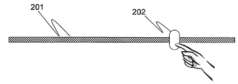
- FIG. 2 is a diagram illustrating an example of the slide bar 107.
- the slide bar 107 includes a bar 201 that indicates a range in which the set value can be adjusted, and a knob 202 that moves along the bar 201. The position of the knob 202 indicates the current set value.
- the display input control unit 102 detects a touch position where a touch operation is performed on the display screen 106 and notifies the control unit 104 of the touch position.
- the storage unit 103 stores the current set value and the adjustable range of the set value.
- the control unit 104 detects a predetermined first operation and second operation performed on the display screen 106 based on the touch position notified from the display input control unit 102.
- the first operation is a drag operation in the direction along the slide bar 107, and the control unit 104 detects that the touch position has moved along the slide bar 107 as having been performed.
- the second operation is not particularly limited as long as it is different from the first operation.
- the second operation is an operation in which the touch position moves in the normal direction of the slide bar 107.
- the second operation is a drag operation in the normal direction of the slide bar 107, and the control unit 104 performs the second operation indicating that the touch position has moved in the normal direction of the slide bar. Detect as a thing.
- the slide bar 107 is assumed to be the one shown in FIG. 2, the direction along the slide bar 107 is referred to as the parallel direction of the slide bar 107, and the normal direction of the slide bar 107 is the slide bar 107. It shall be expressed as the vertical direction.
- the slide bar control unit 105 generates display information indicating the slide bar 107 based on the set value and the adjustable range stored in the storage unit 103, and sends the display information to the display input control unit 102 via the control unit 104. Notice. More specifically, the display information indicates the length of the bar 201, the size of the knob 202, the position of the knob 202 on the bar 201, and the like.
- the slide bar control unit 105 updates the display information and adjusts the setting value stored in the storage unit 103 according to the operation contents of the first operation and the second operation detected by the control unit 104. .
- the slide bar control unit 105 when the first operation is detected, the slide bar control unit 105 generates and displays display information in which the position of the knob 202 is changed by the same distance as the parallel movement distance that is the movement distance of the touch position by the first operation. Notify the input control unit 102. Then, the slide bar control unit 105 changes the setting value stored in the storage unit 103 to a value indicated by the changed position of the knob 202.
- the slide bar control unit 105 When the second operation is detected, the slide bar control unit 105 generates display information in which the position of the knob 202 is changed by a distance corresponding to the vertical movement distance that is the movement distance of the touch position by the second operation. To the display input control unit 102. Then, the slide bar control unit 105 changes the setting value stored in the storage unit 103 to a value indicated by the changed position of the knob 202.
- the user can intuitively understand that the set value can be adjusted by performing the first operation of dragging the knob 202 in the parallel direction of the bar 201.
- the setting value can be adjusted by dragging the knob 202 in the vertical direction of the bar 201.
- the slide bar 107 in FIG. 2 is designed as a side view of a bolt into which a nut is screwed. More specifically, diagonal lines simulating bolt threads are drawn on the bar 201.
- the slide bar 107 By applying the above design to the slide bar 107, it is possible to urge the user to move the nut along the bolt by rotating the nut. Therefore, the user can intuitively grasp that the setting value can be adjusted by moving the knob 202 in the parallel direction of the bar 201 by dragging the knob 202 in the vertical direction of the bar 201.
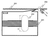
- FIG. 3 is an enlarged view of the vicinity of the knob 202 of the slide bar 107.
- the diagonal lines 211 of the bar 201 are provided at regular intervals.
- an angle formed by the oblique line 211 and the tangent line of the slide bar 107 is a.
- the angle formed by the oblique line 211 and the tangent to the slide bar 107 may be referred to as an inclination angle.
- the rate of change of the movement distance C of the knob 202 with respect to the vertical movement distance B changes in accordance with the oblique line inclination angle a, and becomes smaller as the oblique line inclination angle a approaches 90 degrees, and the oblique line inclination angle a becomes smaller. The closer to 0 degrees, the larger.
- the coefficient n and the inclination angle a may be set by the user.
- the coefficient n and the inclination angle a are preferably set so that n ⁇ c / b is smaller than 1.
- the change rate of the set value with respect to the vertical movement distance is smaller than the change rate of the set value with respect to the parallel movement distance.
- the user can roughly adjust the setting value by performing a drag operation in the parallel direction of the slide bar 107, and can finely adjust the setting value by performing a drag operation in the vertical direction of the slide bar 107. become.
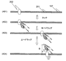
- FIG. 4 is an explanatory diagram showing the state of the slide bar and the user operation in the setting value adjustment operation by the mobile terminal 100
- FIG. 5 is a flowchart showing the flow of the setting value adjustment operation by the mobile terminal 100.
- the slide bar control unit 105 acquires the set value and the adjustable range from the storage unit 103 via the control unit 104, and based on the set value and the adjustable range. Display information indicating a slide bar is generated and notified to the display input control unit 102.
- the display input control unit 102 displays the slide bar 107 on the display screen 106 of the touch panel 101 according to the notified display information (state 401).
- the display input control unit 102 detects the touch position and notifies the control unit 104 (step 501).
- the control unit 104 determines whether or not the knob 202 of the slide bar 107 is touched based on the notified touch position. For example, the control unit 104 identifies the display area of the knob 202 from the display information generated by the slide bar control unit 105. If the touch position is included in the display area, the control unit 104 determines that the knob 202 has been touched, and displays the display. If the touch position is not included in the area, it is determined that the knob 202 is not touched (step 502).
- the control unit 104 determines whether or not the touch position notified from the display input control unit 102 has moved. When the touch position moves, the control unit 104 determines that the user has performed a drag operation (step 503), and confirms the moving direction of the touch position (step 504). When the notification of the touch position is completed without moving the touch position, the control unit 104 determines that the setting value is not adjusted and ends the process.
- the control unit 104 obtains the movement distance of the touch position as a parallel movement distance, and notifies the slide bar control unit 105 of the parallel movement distance.
- the slide bar control unit 105 determines the notified parallel movement distance as the movement distance of the knob (step 505).
- the control unit 104 obtains the movement distance of the touch position as the vertical movement distance and notifies the slide bar control unit 105 of the vertical movement distance.
- the slide bar control unit 105 determines the movement distance of the knob 202 according to the notified vertical movement distance (step 506).
- the coefficient n, the oblique angle a, and the oblique lengths b and c are stored in advance in the storage unit 103, for example, and the slide bar control unit 105 refers to the stored information.
- the slide bar control unit 105 changes the set value in the storage unit 103 based on the movement distance of the knob 202. Further, the slide bar control unit 105 generates display information in which the position of the knob 202 is changed, and notifies the display information to the display input control unit 102 via the control unit 104.
- the display input control unit 102 displays the slide bar 107 on the display screen 106 of the touch panel 101 according to the notified display information (step 506).
- control unit 104 confirms whether or not the notification of the touch position has ended, and determines whether or not the user has released the knob 202 (step 507).
- control unit 104 determines that the user has not released the knob 202, and returns to the process of step 503. On the other hand, when the notification of the touch position is completed, the control unit 104 determines that the user has released the knob 202. Thereby, the set value is confirmed (step 508), and the process is terminated.
- the slide in which the knob 202 has moved to the right as in the state 403 is displayed on the display screen 106.
- the slide bar 107 in which the knob 202 is further moved is displayed on the display screen as in the state 404. become.
- the slide bar control unit 105 may change the moving direction of the knob 202 in accordance with the changing direction of the touch position. For example, in the first operation, the slide bar control unit 105 moves the knob 202 to the left when the touch position changes to the left, and moves the knob 202 to the right when the touch position changes to the right. In the second operation, the slide bar control unit 105 moves the knob 202 to the right when the touch position changes upward, and moves the knob 202 to the left when the touch position changes downward. In the second operation, the slide bar control unit 105 may move the knob 202 to the left when the touch position changes upward, and may move the knob 202 to the right when the touch position changes downward.
- the drag operation and the movement of the knob 202 may be performed in real time.
- an animation for rotating the knob may be added so that the nut rotates with respect to the bolt.
- the control unit 104 determines that the first operation and the second operation are performed simultaneously, and the slide bar control unit 105 determines the parallel movement distance and the vertical operation.
- the knob 202 may be moved by the total movement distance of the knob 202 corresponding to each movement distance.
- the setting value is adjusted when the knob 202 is touched in Step 502
- the setting value may be adjusted even when the bar 201 is touched.
- the slide bar control unit 105 moves the knob 202 to the touch position, and then determines whether or not the touch position has moved.
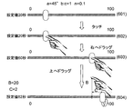
- FIG. 6 is a diagram for explaining a specific example of the operation of the mobile terminal 100.
- the set value is the reproduction start time of the music data.
- the adjustable range of the set value is 0 to 100 seconds
- the set value corresponding to the left end position of the slide bar 107 is 0 seconds
- the set value corresponding to the right end position of the slide bar 107 is 100 seconds.
- the coefficient n is 0.1.
- the reproduction start time can be adjusted in 10 steps with respect to a drag operation in the parallel direction of the slide bar 107. That is, it is assumed that the playback start time can be adjusted in units of 10 seconds in response to a drag operation in the parallel direction of the slide bar 107.
- the initial value of the reproduction start time is assumed to be 20 seconds.
- the user When the user changes the playback start time from 20 seconds to 62 seconds, the user first displays the slide bar 107 (state 601), and then touches the knob 202 of the slide bar 107 to adjust the playback start time. Is started (state 602).
- the user performs a drag operation in the vertical direction of the slide bar 107.
- the display input control unit 102 displays the slide bar 107 for adjusting the setting value on the display screen 106 and performs the touch operation performed on the display screen 106.
- Detect position Based on the touch position detected by the display input control unit 102, the control unit 104 performs a first operation that is a drag operation in the parallel direction of the slide bar 107 and a second operation that is different from the first operation for the slide bar 107. Detects operations.
- the slide bar control unit 105 changes the setting value according to the parallel movement distance that is the movement distance of the touch position by the first operation and the operation content of the second operation.
- the user can finely adjust the setting value by performing the second operation. Therefore, it is possible to reduce the labor required for fine adjustment of the set value, and it is possible to adjust the set value easily, quickly and accurately.
- the second operation is an operation in which the touch position moves in the vertical direction of the slide bar 107. For this reason, since the user can continuously perform the first operation and the second operation without removing the finger from the touch panel 101, the set value can be quickly and easily set to a desired value. become.
- the rate of change of the set value with respect to the vertical movement distance is smaller than the rate of change of the set value with respect to the parallel movement distance. For this reason, the user can roughly adjust the setting value in the drag operation of the slide bar 107 in the parallel direction, and can finely adjust the setting value in the drag operation of the slide bar 107 in the vertical direction.
- the slide bar 107 is drawn with a diagonal line in which the angle formed with the tangent line of the slide bar 107 is determined according to the change rate of the set value with respect to the vertical movement amount. In this case, the user can intuitively grasp the amount of change in the set value according to the vertical movement distance.
- the relationship between the vertical movement distance by the drag operation of the slide bar 107 in the vertical direction and the movement distance (change amount of the setting value) of the knob 202 is clearly indicated by the slanted inclination angle.
- the relationship between the vertical movement distance and the movement distance of the knob 202 may be clearly indicated by another method.
- the size of the knob 202 is determined according to the change rate of the movement distance of the knob 202 (change rate of the set value) with respect to the vertical movement distance.
- the slide bar control unit 105 may add an animation for rotating the knob 202 around the slide bar 107 as a rotation axis at a rotation speed corresponding to the change rate of the set value with respect to the vertical movement amount.
- the second operation is a drag operation of the slide bar 107 in the vertical direction, and the operation content of the second operation is the vertical movement distance.
- the second operation and the content of the operation may be different.
- the second operation may be a click operation or a long press operation on the bar 201 or the knob 202.
- the slide bar control unit 105 changes the setting value according to, for example, the number of click operations, the length of time the button is pressed, and the like.
- the second operation may be a flick operation that moves the touch position quickly by a short distance.
- the slide bar control unit 105 changes the setting value according to the moving speed of the touch position in the flick operation.
- the slide bar control unit 105 moves the slide bar 107 in the vertical direction instead of changing the setting value according to the vertical movement distance.
- the set value may be changed according to the moving speed or moving acceleration of the touch position, or the set value may be changed according to a predetermined combination of the vertical moving distance, moving speed, and moving acceleration.
- the slide bar control unit 105 may change the set value according to the product B ⁇ B ′ of the vertical movement distance B and the movement speed B ′. Good.
- the user can change the setting value greatly as the user drags quickly. For this reason, for example, when the range of setting values that can be adjusted by the second operation is wide, the user quickly drags to change the setting value to a desired value, and then the user slowly drags to set the desired value. The value can be Therefore, the set value can be set to a desired value quickly and easily.
- the shape of the bar 201 of the slide bar 107 is linear, but may be other shapes.
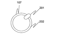
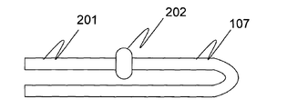
- the bar 201 may have a circular shape as shown in FIG. 8, or may have a shape bent at a certain position as shown in FIG.
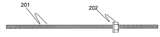
- the shape of the knob 202 is represented by an elliptical shape, it may be a shape closer to the side view of the nut as shown in FIG.
- the electronic device is not limited to the portable terminal 100 and can be changed as appropriate.
- the display input control unit 102 may simultaneously display a plurality of slide bars 107 for adjusting each of a plurality of setting values on the display screen 106.
- the second operation the operation in which the touch position is moved mainly in the normal direction of the slide bar 107 has been described as an example.
- the second operation is not limited to such an operation, and can be appropriately changed.
Landscapes
- Engineering & Computer Science (AREA)
- General Engineering & Computer Science (AREA)
- Theoretical Computer Science (AREA)
- Human Computer Interaction (AREA)
- Physics & Mathematics (AREA)
- General Physics & Mathematics (AREA)
- User Interface Of Digital Computer (AREA)
- Position Input By Displaying (AREA)
Abstract
Description
Claims (9)
- 表示画面を備え、前記表示画面に対するタッチ操作を受け付ける表示入力部と、
設定値を調整するためのスライドバーを前記表示画面に表示するとともに、前記表示画面上の前記タッチ操作が行われたタッチ位置を検出する表示入力制御部と、
前記表示入力制御部にて検出されたタッチ位置に基づいて、前記スライドバーに沿った方向へのドラッグ操作である第1操作と、前記表示画面に対する前記第1操作と異なる所定の第2操作とを検出する制御部と、
前記第1操作による前記タッチ位置の移動距離である平行移動距離と、前記第2操作の操作内容とに応じて前記設定値を変化させるスライドバー制御部と、を有する電子機器。 - 請求項1に記載の電子機器において、
前記第2操作は、前記タッチ位置が前記スライドバーの法線方向に移動するような操作である、電子機器。 - 請求項2に記載の電子機器において、
前記操作内容は、前記法線方向への前記タッチ位置の移動距離である垂直移動距離と、前記法線方向への前記タッチ位置の移動速度と、前記法線方向への前記タッチ位置の移動加速度との少なくとも一つを含む、電子機器。 - 請求項3に記載の電子機器において、
前記垂直移動距離に対する前記設定値の変化率は、前記平行移動距離に対する前記設定値の変化率より小さい、電子機器。 - 請求項3または4に記載の電子機器において、
前記操作内容は、前記垂直移動距離および前記移動速度の積である、電子機器。 - 請求項3ないし5のいずれか1項に記載の電子機器において、
前記スライドバーには、当該スライドバーの接線との成す角度が前記垂直移動量に対する前記設定値の変化率に応じて定められた斜線が描かれている、電子機器。 - 請求項3ないし5のいずれか1項に記載の電子機器において、
前記スライドバーは、大きさが前記垂直移動量に対する前記設定値の変化率に応じて定められたつまみを有する、電子機器。 - 請求項7に記載の電子機器において、
前記スライドバー制御部は、前記垂直移動量に対する前記設定値の変化率に応じた回転速度で、前記つまみを前記スライドバーを回転軸として回転させる、電子機器。 - 表示画面を備える電子機器の設定値調整方法であって、
設定値を調整するためのスライドバーを前記表示画面に表示し、
前記表示画面上の前記タッチ操作が行われたタッチ位置を検出し、
前記タッチ位置に基づいて、前記表示画面に対して前記スライドバーに沿った方向へのドラッグ操作である第1操作と、前記スライドバーに対する前記第1操作と異なる所定の第2操作とを検出し、
前記第1操作による前記タッチ位置の移動距離である平行移動距離と、前記第2操作の操作内容とに応じて前記設定値を変化させる、設定値調整方法。
Priority Applications (4)
| Application Number | Priority Date | Filing Date | Title |
|---|---|---|---|
| US13/704,219 US9058073B2 (en) | 2010-06-17 | 2011-04-15 | Electronic device and adjustment method for adjusting setting value |
| EP11795457.8A EP2584442A4 (en) | 2010-06-17 | 2011-04-15 | ELECTRONIC DEVICE AND SETUP METHOD THEREFOR |
| CN201180029870.6A CN102971697B (zh) | 2010-06-17 | 2011-04-15 | 电子设备和用于调整设置值的调整方法 |
| JP2012520312A JP5819820B2 (ja) | 2010-06-17 | 2011-04-15 | 電子機器およびその設定値調整方法 |
Applications Claiming Priority (2)
| Application Number | Priority Date | Filing Date | Title |
|---|---|---|---|
| JP2010-138707 | 2010-06-17 | ||
| JP2010138707 | 2010-06-17 |
Publications (1)
| Publication Number | Publication Date |
|---|---|
| WO2011158549A1 true WO2011158549A1 (ja) | 2011-12-22 |
Family
ID=45347961
Family Applications (1)
| Application Number | Title | Priority Date | Filing Date |
|---|---|---|---|
| PCT/JP2011/059365 Ceased WO2011158549A1 (ja) | 2010-06-17 | 2011-04-15 | 電子機器およびその設定値調整方法 |
Country Status (5)
| Country | Link |
|---|---|
| US (1) | US9058073B2 (ja) |
| EP (1) | EP2584442A4 (ja) |
| JP (2) | JP5819820B2 (ja) |
| CN (1) | CN102971697B (ja) |
| WO (1) | WO2011158549A1 (ja) |
Cited By (3)
| Publication number | Priority date | Publication date | Assignee | Title |
|---|---|---|---|---|
| JP2015002471A (ja) * | 2013-06-17 | 2015-01-05 | キヤノン株式会社 | 表示制御装置、方法及びプログラム並びに記憶媒体 |
| JP2016004411A (ja) * | 2014-06-17 | 2016-01-12 | 東芝ライテック株式会社 | 操作装置および照明装置 |
| JP2018041491A (ja) * | 2017-10-26 | 2018-03-15 | オリンパス株式会社 | 電子機器、アイコン表示方法およびアイコン表示用プログラム |
Families Citing this family (26)
| Publication number | Priority date | Publication date | Assignee | Title |
|---|---|---|---|---|
| JP5971033B2 (ja) * | 2012-08-29 | 2016-08-17 | 富士ゼロックス株式会社 | 情報処理装置及び情報処理プログラム |
| KR101505832B1 (ko) * | 2013-08-19 | 2015-03-25 | 삼성전자주식회사 | 의료 영상을 표시하는 방법 및 이를 위한 장치 |
| JP2015106174A (ja) * | 2013-11-28 | 2015-06-08 | 京セラ株式会社 | 電子機器 |
| WO2015097860A1 (ja) * | 2013-12-27 | 2015-07-02 | 楽天株式会社 | 情報処理装置、情報処理方法、および情報処理プログラム |
| CN104978125B (zh) * | 2014-04-04 | 2018-06-08 | 宏碁股份有限公司 | 电子装置以及用户界面控制方法 |
| CN104156149B (zh) | 2014-07-18 | 2016-04-13 | 小米科技有限责任公司 | 拍摄参数调节方法及装置 |
| US10425575B2 (en) * | 2014-08-12 | 2019-09-24 | Sony Corporation | Information processing device, program, and information processing method |
| US9992115B2 (en) * | 2014-08-22 | 2018-06-05 | Xiaomi Inc. | Method and device for controlling traffic of mobile router |
| DE102014116075A1 (de) * | 2014-11-04 | 2016-05-04 | Vorwerk & Co. Interholding Gmbh | Elektrisches Küchengerät |
| KR101642947B1 (ko) * | 2015-01-16 | 2016-08-10 | 네이버 주식회사 | 만화 데이터 생성 장치, 방법, 컴퓨터 프로그램 및 만화 데이터 표시 장치 |
| JP6202082B2 (ja) * | 2015-12-22 | 2017-09-27 | ダイキン工業株式会社 | 設定値変更装置 |
| DE102016112338A1 (de) * | 2016-07-06 | 2018-01-11 | Miele & Cie. Kg | Bedienvorrichtung mit einem Berührbildschirm für ein elektrisches Gerät |
| JP6890991B2 (ja) * | 2017-01-31 | 2021-06-18 | キヤノン株式会社 | 画像処理装置、制御方法及びプログラム |
| CN108829332B (zh) * | 2018-05-22 | 2023-10-03 | 珠海格力电器股份有限公司 | 触摸滑条的控制方法、遥控器、家用电器、计算机可读存储介质及触摸滑条装置 |
| US10643365B1 (en) * | 2018-11-20 | 2020-05-05 | Adobe Inc. | Deformation mesh control for a computer animated artwork |
| US11194461B2 (en) * | 2019-01-15 | 2021-12-07 | Fujifilm Medical Systems U.S.A., Inc. | Smooth image scrolling with dynamic scroll extension |
| CN109946990B (zh) * | 2019-04-19 | 2020-07-14 | 北京远鼎科技有限公司 | 一种交互方法、交互终端及智能家居系统 |
| CN109946989B (zh) * | 2019-04-19 | 2020-07-14 | 北京远鼎科技有限公司 | 一种交互终端及智能家居系统 |
| CN110244888A (zh) * | 2019-06-11 | 2019-09-17 | 惠州Tcl移动通信有限公司 | 一种行为模式的设置方法、装置、存储介质及终端 |
| JP7037196B2 (ja) * | 2019-12-27 | 2022-03-16 | タグル株式会社 | アスレチック情報処理システム |
| JP2021149439A (ja) * | 2020-03-18 | 2021-09-27 | 富士フイルムビジネスイノベーション株式会社 | 情報処理装置及び情報処理プログラム |
| CN112083869A (zh) * | 2020-08-27 | 2020-12-15 | 小米数字科技有限公司 | 数字输入方法、数字输入装置及存储介质 |
| CN112083868A (zh) * | 2020-08-27 | 2020-12-15 | 小米数字科技有限公司 | 数字输入方法、数字输入装置及存储介质 |
| JP7639316B2 (ja) * | 2020-12-11 | 2025-03-05 | セイコーエプソン株式会社 | ソフトウェアスイッチプログラム、選択肢の選択方法および情報処理装置 |
| US11693551B2 (en) | 2021-05-21 | 2023-07-04 | Huawei Technologies Co., Ltd. | Methods and systems for providing feedback for multi-precision mid-air gestures on a gesture-controlled device |
| US11579769B1 (en) * | 2021-12-14 | 2023-02-14 | International Business Machines Corporation | Graphic device for controlling displayed object movement and/or screen scrolling |
Citations (3)
| Publication number | Priority date | Publication date | Assignee | Title |
|---|---|---|---|---|
| JP2005244360A (ja) * | 2004-02-24 | 2005-09-08 | Kyocera Mita Corp | 画像処理装置 |
| JP2009230468A (ja) * | 2008-03-24 | 2009-10-08 | Seiko Epson Corp | 再生装置、再生装置の制御方法および制御プログラム |
| JP2009295147A (ja) | 2008-05-07 | 2009-12-17 | Hoya Corp | スクロール表示可能な情報処理装置 |
Family Cites Families (10)
| Publication number | Priority date | Publication date | Assignee | Title |
|---|---|---|---|---|
| JPH0382855A (ja) | 1989-08-24 | 1991-04-08 | Takaramoto Shoji Kk | 意匠糸及びその製造方法 |
| JP3145773B2 (ja) | 1992-03-30 | 2001-03-12 | シャープ株式会社 | 画像形成装置を制御するcpuの暴走検知方法 |
| JP3082855B1 (ja) | 1999-08-24 | 2000-08-28 | 高温酸性ガス固定化技術研究組合 | ハイドロガーネットの製造法及びハイドロガーネットによる高温酸性排ガスの除去法 |
| AU4595501A (en) * | 2000-03-22 | 2001-10-03 | Sony Electronics Inc. | Data entry user interface |
| US6922816B1 (en) | 2000-08-24 | 2005-07-26 | International Business Machines Corporation | Method and system for adjusting settings with slider controls having variable sensitivity |
| JP2008048105A (ja) | 2006-08-14 | 2008-02-28 | Fujitsu Ten Ltd | 音響装置および音響装置における音量制御方法 |
| KR100837283B1 (ko) * | 2007-09-10 | 2008-06-11 | (주)익스트라스탠다드 | 터치스크린을 구비한 휴대용 단말기 |
| KR101446521B1 (ko) | 2008-08-12 | 2014-11-03 | 삼성전자주식회사 | 터치 스크린의 정보 스크롤 제어 방법 및 장치 |
| KR101565378B1 (ko) * | 2008-09-03 | 2015-11-03 | 엘지전자 주식회사 | 이동단말기 및 그 제어 방법 |
| US8984431B2 (en) * | 2009-03-16 | 2015-03-17 | Apple Inc. | Device, method, and graphical user interface for moving a current position in content at a variable scrubbing rate |
-
2011
- 2011-04-15 WO PCT/JP2011/059365 patent/WO2011158549A1/ja not_active Ceased
- 2011-04-15 EP EP11795457.8A patent/EP2584442A4/en not_active Withdrawn
- 2011-04-15 JP JP2012520312A patent/JP5819820B2/ja not_active Expired - Fee Related
- 2011-04-15 US US13/704,219 patent/US9058073B2/en not_active Expired - Fee Related
- 2011-04-15 CN CN201180029870.6A patent/CN102971697B/zh not_active Expired - Fee Related
-
2015
- 2015-09-29 JP JP2015192041A patent/JP2016026357A/ja not_active Ceased
Patent Citations (3)
| Publication number | Priority date | Publication date | Assignee | Title |
|---|---|---|---|---|
| JP2005244360A (ja) * | 2004-02-24 | 2005-09-08 | Kyocera Mita Corp | 画像処理装置 |
| JP2009230468A (ja) * | 2008-03-24 | 2009-10-08 | Seiko Epson Corp | 再生装置、再生装置の制御方法および制御プログラム |
| JP2009295147A (ja) | 2008-05-07 | 2009-12-17 | Hoya Corp | スクロール表示可能な情報処理装置 |
Non-Patent Citations (1)
| Title |
|---|
| See also references of EP2584442A4 |
Cited By (3)
| Publication number | Priority date | Publication date | Assignee | Title |
|---|---|---|---|---|
| JP2015002471A (ja) * | 2013-06-17 | 2015-01-05 | キヤノン株式会社 | 表示制御装置、方法及びプログラム並びに記憶媒体 |
| JP2016004411A (ja) * | 2014-06-17 | 2016-01-12 | 東芝ライテック株式会社 | 操作装置および照明装置 |
| JP2018041491A (ja) * | 2017-10-26 | 2018-03-15 | オリンパス株式会社 | 電子機器、アイコン表示方法およびアイコン表示用プログラム |
Also Published As
| Publication number | Publication date |
|---|---|
| EP2584442A1 (en) | 2013-04-24 |
| JP2016026357A (ja) | 2016-02-12 |
| EP2584442A4 (en) | 2014-04-30 |
| CN102971697B (zh) | 2016-08-24 |
| CN102971697A (zh) | 2013-03-13 |
| US20130093709A1 (en) | 2013-04-18 |
| JP5819820B2 (ja) | 2015-11-24 |
| JPWO2011158549A1 (ja) | 2013-08-19 |
| US9058073B2 (en) | 2015-06-16 |
Similar Documents
| Publication | Publication Date | Title |
|---|---|---|
| JP5819820B2 (ja) | 電子機器およびその設定値調整方法 | |
| US9442649B2 (en) | Optimal display and zoom of objects and text in a document | |
| JP5489379B1 (ja) | スクロール装置、スクロール方法及びプログラム | |
| CN103941875B (zh) | 一种翻页方法、装置及终端 | |
| JP5304577B2 (ja) | 携帯情報端末および表示制御方法 | |
| EP2801020B1 (en) | Panning animations of a displayed user interface | |
| KR20120066122A (ko) | 타임라인 바를 이용한 터치스크린 제어방법, 장치 및 이를 위한 프로그램이 기록된 기록매체 및 사용자 단말 | |
| US20110304584A1 (en) | Touch screen control method and touch screen device using the same | |
| US10656817B2 (en) | Display control device, display control method, and program | |
| US20130007666A1 (en) | Electronic device with touch screen device, method of moving function icon and computer readable storage media comprising computer executable instructions | |
| EP2530573B1 (en) | Touch control method and electronic apparatus | |
| CN103631419B (zh) | 基于遥控触摸板的光标定位方法及系统 | |
| CN103176744B (zh) | 一种显示设备及其信息处理方法 | |
| WO2015154338A1 (zh) | 一种基于手势操作调整终端窗口显示的方法及装置 | |
| JP2011081440A5 (ja) | 表示制御装置、表示制御方法及び表示制御プログラム | |
| JP2013114558A5 (ja) | ||
| JP2009295147A (ja) | スクロール表示可能な情報処理装置 | |
| JP2014038560A5 (ja) | 情報処理装置、情報処理装置の制御方法及びプログラム | |
| US20120134641A1 (en) | Electronic Apparatus and Method of Displaying Bar | |
| KR101090322B1 (ko) | 터치스크린 제어방법, 이를 이용하는 터치스크린 장치, 및 이를 포함하는 모바일 기기 | |
| JP5514264B2 (ja) | 電子機器、表示方法 | |
| JP2012194727A (ja) | 電子機器 | |
| JP6213125B2 (ja) | 電子機器、電子機器の制御方法及びプログラム | |
| JP2012137917A (ja) | 表示装置、方法及びプログラム | |
| KR20120053802A (ko) | 휴대용 기기에서 화면 제어 방법 |
Legal Events
| Date | Code | Title | Description |
|---|---|---|---|
| WWE | Wipo information: entry into national phase |
Ref document number: 201180029870.6 Country of ref document: CN |
|
| 121 | Ep: the epo has been informed by wipo that ep was designated in this application |
Ref document number: 11795457 Country of ref document: EP Kind code of ref document: A1 |
|
| REEP | Request for entry into the european phase |
Ref document number: 2011795457 Country of ref document: EP |
|
| WWE | Wipo information: entry into national phase |
Ref document number: 2011795457 Country of ref document: EP |
|
| WWE | Wipo information: entry into national phase |
Ref document number: 2012520312 Country of ref document: JP |
|
| WWE | Wipo information: entry into national phase |
Ref document number: 13704219 Country of ref document: US |
|
| NENP | Non-entry into the national phase |
Ref country code: DE |