WO2011162060A1 - 車体前部構造 - Google Patents
車体前部構造 Download PDFInfo
- Publication number
- WO2011162060A1 WO2011162060A1 PCT/JP2011/061765 JP2011061765W WO2011162060A1 WO 2011162060 A1 WO2011162060 A1 WO 2011162060A1 JP 2011061765 W JP2011061765 W JP 2011061765W WO 2011162060 A1 WO2011162060 A1 WO 2011162060A1
- Authority
- WO
- WIPO (PCT)
- Prior art keywords
- dashboard
- center frame
- vehicle body
- vertical wall
- joined
- Prior art date
- Legal status (The legal status is an assumption and is not a legal conclusion. Google has not performed a legal analysis and makes no representation as to the accuracy of the status listed.)
- Ceased
Links
Images




Classifications
-
- B—PERFORMING OPERATIONS; TRANSPORTING
- B62—LAND VEHICLES FOR TRAVELLING OTHERWISE THAN ON RAILS
- B62D—MOTOR VEHICLES; TRAILERS
- B62D25/00—Superstructure or monocoque structure sub-units; Parts or details thereof not otherwise provided for
- B62D25/08—Front or rear portions
-
- B—PERFORMING OPERATIONS; TRANSPORTING
- B62—LAND VEHICLES FOR TRAVELLING OTHERWISE THAN ON RAILS
- B62D—MOTOR VEHICLES; TRAILERS
- B62D25/00—Superstructure or monocoque structure sub-units; Parts or details thereof not otherwise provided for
- B62D25/08—Front or rear portions
- B62D25/14—Dashboards as superstructure sub-units
Definitions
- the present invention relates to a vehicle body front part structure.
- This application claims priority based on Japanese Patent Application No. 2010-143870 filed in Japan on June 24, 2010, the contents of which are incorporated herein by reference.
- the vehicle body includes a cabin (cabinet) in which an occupant gets in, an engine room that is disposed in front of the cabin and houses an engine, and a floor portion that is provided on the lower surface of the cabin.
- a pair of hinge pillars that support the side doors via hinges extend in the vertical direction at both corners in the front vehicle width direction of the cabin, and between the upper portions of both hinge pillars, the closed doors extend in the vehicle width direction.
- a cowl with a cross-sectional structure is stretched over.
- a dashboard that partitions the engine room and the cabin is provided in a portion surrounded by the floor portion, the pair of hinge pillars, and the cowl.
- the dashboard is a component that only partitions the engine room and the cabin, the dashboard is often formed of a thin plate for weight reduction. For this reason, there is a possibility that the dashboard vibrates during traveling. Therefore, in order to suppress this membrane vibration, a reinforcing member extending in the vertical direction is provided on the dashboard. This may increase the rigidity of the dashboard.
- the reinforcing member is formed in the shape of a U-shaped section with the dashboard side open, and a closed section is configured by joining a flange provided at the open end to the dashboard. The upper end of the reinforcing member extends to the cowl, and is joined to the lower surface of the cowl (see, for example, Patent Document 1).
- an object of the present invention is to provide a vehicle body front structure that can effectively suppress dashboard membrane vibration.
- a vehicle body front portion structure includes a center frame that extends along the vertical direction of the vehicle body and has an upper end flange portion that is bent rearward at the upper end;
- a dashboard lower having a vertical wall and a bent portion bent toward the rear at the upper edge of the first vertical wall; and the upper end flange portion and the bent portion overlap each other.
- a closed cross-section structure portion is formed between the center frame and the bent portion.
- the vehicle body front structure according to (1) further includes a windshield support panel having a second vertical wall formed on the same plane as the first vertical wall; and the bending of the dashboard lower It is preferable that the second vertical wall of the windshield support panel is joined to the portion.
- a lower end flange portion is formed at a lower end of the center frame; a tunnel portion is provided at a lower center of the dashboard lower in the width direction of the vehicle body; Preferably, the lower end flange portion is joined to the tunnel portion.
- the vehicle body front structure according to (3) further includes a dashboard cross member extending along a vehicle width direction on the dashboard lower; the dashboard cross member and the center frame are joined to each other.
- a dashboard cross member extending along a vehicle width direction on the dashboard lower; the dashboard cross member and the center frame are joined to each other.
- the center frame has a pair of side walls facing each other and a bottom wall connecting the lower ends of the pair of side walls, and is directed rearward. It is preferable that the ridgeline of the center frame, which is a connecting portion between the side wall and the bottom wall, is formed linearly.
- the closed cross-section structure portion is formed between the bending portion that is the starting point of the membrane vibration of the first vertical wall of the dashboard lower and the center frame.
- the rigidity of the part can be increased. Thereby, it becomes possible to effectively suppress the membrane vibration of the dashboard lower.
- the rigidity of the bent portion can be further increased by using the second vertical wall of the windshield panel having high rigidity. For this reason, it becomes possible to suppress the membrane vibration of the dashboard lower more reliably.
- the lower end of the center frame can be supported by the highly rigid tunnel part. For this reason, the rigidity of the center frame can be increased, and the membrane vibration of the dashboard lower can be more reliably suppressed.
- the rigidity of the entire dashboard lower can be further increased. Furthermore, since the front collision load transmitted from the dashboard cross member is transmitted to the tunnel portion via the center frame, the front collision load can be dispersed.
- the support effect of the center frame with respect to the dashboard lower can be enhanced by tilting the center frame.
- the ridgeline of the center frame is formed linearly, the effect of supporting the center frame with respect to the dashboard lower can be further enhanced.
- the front collision load is efficiently transmitted to the tunnel portion via the center frame, the front body structure of the vehicle body can disperse the front collision load.
- FIG. 2 is a cross-sectional perspective view taken along line AA in FIG. 1.
- FIG. 3 is a sectional view taken along line BB in FIG. 2.
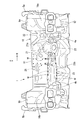
- FIG. 1 is a perspective view of the dashboard lower as seen from the cabin side
- FIG. 2 is a plan view of the dashboard lower as seen from the cabin side
- FIG. 3 is a plan view of the dashboard lower as seen from the engine room side. is there.
- the vehicle body front structure 1 includes front side frames 4 a and 4 b, front pillars 5 a and 5 b, upper members 6 a and 6 b, a dashboard lower 10, and a floor panel 9. ing.
- the front side frames 4 a and 4 b are arranged in front and constitute left and right frame portions of the engine room 2.
- the front pillars 5a and 5b are arranged behind the front side frames 4a and 4b and on the left and right outer sides, and extend in the vertical direction.
- the upper members 6a and 6b are disposed above the front side frames 4a and 4b.
- the front ends are joined to the front ends of the front side frames 4a and 4b, and the rear ends are joined to the front pillars 5a and 5b. .
- the dashboard lower 10 divides the engine room 2 and the cabin 3 disposed behind the dashboard, and is joined to the front side frames 4a and 4b, the front pillars 5a and 5b, and the upper members 6a and 6b.
- the floor panel 9 is joined to the lower edge of the dashboard lower 10.
- the dashboard lower 10 is formed by pressing a flat metal member or the like, and has a vertical wall (first vertical wall) 11 along the vertical direction, and a downward slope from the lower part of the vertical wall 11 toward the rear. And an inclined wall 12 extending in the direction. Further, wheel house portions 16a and 16b are provided on the left and right sides of the dashboard lower 10, respectively.
- Each wheel house portion 16a, 16b is formed to bulge toward the cabin 3 side.
- Gussets 18a and 18b are provided on the upper portions of the wheel house portions 16a and 16b, respectively.
- the rear ends of the front side frames 4a and 4b are joined by spot welding to the vehicle width direction center ends of the gussets 18a and 18b with the dashboard lower 10 interposed therebetween.
- front pillars 5a and 5b are joined to the outer ends of the gussets 18a and 18b in the vehicle width direction by spot welding, respectively.
- a tunnel portion 13 bulging upward is integrally formed at the inclined wall 12 of the dashboard lower 10, that is, at the lower portion of the dashboard lower 10 at the center in the vehicle width direction. ing.
- a driver seat side step unit 14 is disposed on the left side of the tunnel unit 13, and a passenger seat side step unit 15 is disposed on the right side.
- a steering opening 20 that connects the engine room 2 and the cabin 3 is formed at the boundary between the vertical wall 11 and the inclined wall 12 in the driver seat side step portion 14.
- the steering opening 20 is formed for inserting a steering shaft (not shown) or a universal joint connected to the steering shaft.
- a steering joint cover 21 that closes the steering opening 20 is attached to the steering opening 20 from the engine room 2 side.
- the steering joint cover 21 is formed in a cup shape bulging toward the engine room 2 side, and a joint insertion port 22 is formed for inserting a steering shaft and a universal joint (not shown).
- a dashboard cross member extending in the vehicle width direction, that is, along the left and right front side frames 4a and 4b, at a position corresponding to the steering joint cover 21. 23 is provided.
- the dashboard cross member 23 increases the rigidity of the dashboard lower 10 and disperses the front collision load.
- the cross-sectional shape of the dashboard cross member 23 as viewed in a cross section perpendicular to the length direction is formed in a substantially hat shape.
- the opening side of the dashboard cross member 23 is joined to the dashboard lower 10 side by spot welding to form a closed cross-section structure portion 24 (see FIGS. 5 and 6).
- the dashboard cross member 23 has a closed cross-section structure portion 24 that is a closed cross-section structure.
- the dashboard cross member 23 is divided into left and right parts with the steering joint cover 21 interposed therebetween. That is, the dashboard cross member 23 includes a left cross member 23a and a right cross member 23b. One end of each of the left cross member 23a and the right cross member 23b is joined to the steering joint cover 21 by spot welding. That is, the left cross member 23 a and the right cross member 23 b are connected via the steering joint cover 21. On the other hand, the other ends of the left cross member 23a and the right cross member 23b are joined to the corresponding left and right front side frames 4a and 4b by spot welding.
- a recess 31 is formed on the surface of the dashboard lower 10 on the cabin 3 side so as to be elongated in the left-right direction at a portion corresponding to the right cross member 23b.
- the recess 31 is formed by bulging the dashboard lower 10 toward the engine room 2 side. Thereby, the rigidity of the site
- an accelerator pedal bracket 32 for attaching an accelerator pedal (not shown) is provided on the surface of the vertical wall 11 of the dashboard lower 10 on the cabin 3 side on the upper right side of the steering opening 20. Furthermore, a mounting hole 33 for attaching a brake master cylinder (not shown) is formed in the vertical wall 11 on the upper left side of the steering opening 20.
- a master cylinder stiffener 25 is provided on the surface of the vertical wall 11 on the cabin 3 side at a position corresponding to the mounting hole 33.
- the master cylinder stiffener 25 is formed with unevenness by pressing a flat metal member or the like, and a brake master cylinder (not shown) is attached thereto.
- a damping material fixing panel 26 is provided on the upper side of the vertical wall 11 on the right side of the tunnel portion 13. The damping material fixing panel 26 fixes a not-shown Mel sheet affixed as a damping material of the dashboard lower 10, and has a flat metal member subjected to pressing or the like to form irregularities.
- a bent portion 27 is formed at the upper edge of the vertical wall 11 so as to bend and extend rearward.
- a center frame 28 extending in the vertical direction of the vehicle body is provided between the bent portion 27 of the vertical wall 11 and the tunnel portion 13.
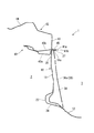
- FIG. 4 is a front view of the center frame
- FIG. 5 is a perspective view of the center frame
- FIG. 6 is a cross-sectional perspective view taken along the line AA of FIG. 1, and FIG. It is sectional drawing which follows the BB line.
- the cross-sectional shape of the center frame 28 viewed in a cross section perpendicular to the longitudinal direction is formed in a substantially hat shape, and the bent portion 27 and the tunnel portion 13 of the vertical wall 11 are formed. It is formed so as to straddle. That is, the center frame 28 includes a frame main body 36 having a substantially U-shaped cross section, and flange portions 29 that bend and extend outward from both side edges of the frame main body 36.
- the center frame 28 has a pair of side walls 36b that face each other and a bottom wall 36a that connects the pair of side walls 36b.
- the frame body 36 is disposed in a downward slope with the opening side facing the vertical wall 11 and the bottom wall 36a of the frame body 36 facing rearward.
- the height of the side wall 36b of the frame main body 36 is set so as to be gradually higher toward the lower side and along the unevenness of the vertical wall 11 so as to correspond to the downward slope of the bottom wall 36a.
- the center frame 28 has the flange portion 29 superimposed on the vertical wall 11 while the bottom wall 36a is inclined downward toward the rear.
- a ridge line portion (ridge line) 37 that is a connection portion between the bottom wall 36a and the side wall 36b is linearly formed.
- a plurality of bead portions 39 are formed on the left and right side walls 36b, 36b and the flange portion 29, respectively.
- the plurality of bead portions 39 increase the rigidity of the center frame 28.
- the flange portion 29 formed in this way is joined by spot welding in a state of being superimposed on the vertical wall 11, and a closed cross-section structure portion 38 is formed between the vertical wall 11 and the center frame 28.
- an upper end flange portion 34 a that is bent and extends rearward is formed at the upper end of the center frame 28 so as to overlap the bent portion 27 of the vertical wall 11.
- the upper end flange portion 34a and the bent portion 27 are overlapped with each other and joined by spot welding.
- a closed cross-section structure portion 35 is formed between the center frame 28 and the bent portion 27.
- a lower end flange portion 34 b extending along the top surface of the tunnel portion 13 is formed at the lower end of the flange portion 29.
- the lower end flange portion 34b is superposed on the top surface of the tunnel portion 13 and joined by spot welding.
- a symbol M shown in FIG. 3 indicates a spot welded portion between the dashboard lower 10, the steering joint cover 21, the dashboard cross member 23, the master cylinder stiffener 25, the damping material fixing panel 26, and the center frame 28. .
- the dashboard upper assembly 40 includes a lower panel 40a and an upper panel 40b formed by pressing a flat metal member, and the lower panel 40a and the upper panel 40b are stacked one above the other. It is configured.
- the lower panel 40a and the upper panel 40b form a closed cross-sectional structure.
- a flange portion 41a and a flange portion 41b are formed on the periphery of the lower panel 40a and the upper panel 40b, respectively.
- the dashboard upper assembly 40 is formed by spot welding with the flange portion 41a and the flange portion 41b overlapped.
- the bent portion 27 of the dashboard lower 10 is joined to the flange portion 41 by spot welding.
- the windshield support panel 42 is formed by pressing a flat metal member or the like, and includes a vertical wall (second vertical wall) 43 and an extending portion 44.
- the bent portion 27 of the dashboard lower 10 is connected to the vertical wall 43 of the windshield support panel 42 with the dashboard upper assembly 40 interposed therebetween.
- the vertical wall 43 is formed on the same plane as the vertical wall 11 of the dashboard lower 10.
- the extending portion 44 is bent and extended forward from the upper edge of the vertical wall 43.
- a flange portion 45 that bends and extends rearward is formed at the lower edge of the vertical wall 43, and the bent portion 27 of the dashboard lower 10 is spotted on the flange portion 45 with the dashboard upper assembly 40 interposed therebetween. They are joined by welding.
- the upper end flange portion 34a of the center frame 28 is joined to the bent portion 27 formed at the upper edge portion of the dashboard lower 10 so that the bent portion 27 and the center frame 28 are connected to each other. Since the closed cross-section structure portion 35 is formed therebetween (see FIG. 7), the rigidity of the bent portion 27 can be effectively increased. For this reason, for example, when the vehicle is traveling, it is possible to effectively suppress membrane vibration starting from the bent portion 27 of the dashboard lower 10.
- the bent portion 27 of the dashboard lower 10 is connected to the windshield support panel 42 with the dashboard upper assembly 40 interposed therebetween. That is, the flange portion 45 is formed on the vertical wall 43 of the windshield support panel 42 having high rigidity. By joining the bent portion 27 of the dashboard lower 10 to the flange portion 45, the rigidity of the bent portion 27 can be further increased. For this reason, the membrane vibration of the dashboard lower 10 can be more reliably suppressed.
- a lower end flange portion 34b extending along the top surface of the tunnel portion 13 is formed at the lower end of the flange portion 29, and the lower end flange portion 34b is spot welded to the top surface of the tunnel portion 13. It is joined. That is, the lower end of the center frame 28 is supported by the tunnel portion 13 having high rigidity. For this reason, the rigidity of the center frame 28 can be increased, and the dashboard lower 10 membrane vibration can be more reliably suppressed.
- the bottom wall 36a of the frame body 36 of the center frame 28 is disposed so as to have a downward slope toward the rear, and a ridge line portion 37 between the bottom wall 36a and the side wall 36b constituting the frame body 36 is provided. It is formed linearly. As the center frame 28 is inclined in this way, the support effect of the center frame 28 on the dashboard lower 10 can be reliably increased. Furthermore, the front collision load transmitted from the dashboard cross member 23 can be efficiently transmitted to the tunnel portion 13 via the center frame 28.
- the left and right front side frames 4a and 4b are joined to the left and right gussets 18 and 19 at the center side end in the vehicle width direction, respectively.
- the left and right front pillars 5a and 5b are joined to the outer ends in the vehicle width direction (see FIGS. 1 and 3). For this reason, the front collision load transmitted from the left left front side frame 4a is transmitted to the left front pillar 5a via the left gusset 18a, so that the vehicle body front structure 1 can disperse the load. . Further, since the front collision load transmitted from the right front side frame 4b on the right side is transmitted to the right front pillar 5b via the right gusset 18b, the vehicle body front structure 1 can disperse the load.
- the present invention is not limited to the above-described embodiment, and includes various modifications made to the above-described embodiment without departing from the spirit of the present invention.
- the dashboard upper assembly 40 to which the bent portion 27 of the dashboard lower 10 is connected has been described using a configuration in which the lower panel 40a and the upper panel 40b are overlapped.
- the present invention is not limited to this, and a dashboard upper composed of only one flat metal member may be used in place of the dashboard upper assembly 40.
- the present invention is not limited to this, and conventionally known metal welding methods such as TIG (tungsten inert gas) welding, MIG (metal inert gas) welding, arc welding such as plasma welding, laser welding, and electron beam welding. Can be adopted as appropriate.
- TIG tungsten inert gas
- MIG metal inert gas
- arc welding such as plasma welding, laser welding, and electron beam welding.
- SYMBOLS 1 Vehicle body front part structure 10 ... Dashboard lower 11, 43 ... Vertical wall 13 ... Tunnel part 23 ... Dashboard cross member 27 ... Bending part 28 ... Center frame 34a ... Upper end flange part 34b ... Lower end flange part 37 ... Ridge line part ( Edge) 42 ... Windshield support panel
Landscapes
- Engineering & Computer Science (AREA)
- Chemical & Material Sciences (AREA)
- Combustion & Propulsion (AREA)
- Transportation (AREA)
- Mechanical Engineering (AREA)
- Body Structure For Vehicles (AREA)
Abstract
Description
本願は、2010年06月24日に、日本に出願された特願2010-143870号に基づき優先権を主張し、その内容をここに援用する。
補強部材は、ダッシュボード側が開放された断面Uの字状に形成されており、開放側端部に設けられたフランジをダッシュボードに接合させることで閉断面を構成している。また、補強部材の上端はカウルまで延設されており、このカウルの下面に接合されている(例えば、特許文献1参照)。
すなわち、
(1)本発明の一態様に係る車体前部構造は、車体の上下方向に沿って延在し、上端に、後方に向かって曲折された上端フランジ部が形成されたセンタフレームと;第1縦壁を有し、この第1縦壁の上縁に、後方に向かって曲折された屈曲部が形成されたダッシュボードロアと;を備え、前記上端フランジ部と前記屈曲部とが互いに重ね合せて接合され、前記センタフレームと前記屈曲部との間に閉断面構造部が形成されている。
次に、この発明の実施形態を図面に基づいて説明する。以下の説明において、車両の進行方向前方を単に前方、進行方向後方を単に後方、車幅方向右方を単に右方、車幅方向左方を単に左方、重力方向上方を単に上方、重力方向下方を単に下方などと表現して説明する場合がある。
図1は、ダッシュボードロアをキャビン側からみた斜視図であり、図2は、ダッシュボードロアをキャビン側からみた平面図であり、図3は、ダッシュボードロアをエンジンルーム側からみた平面図である。
フロントサイドフレーム4a,4bは、前方に配置されてエンジンルーム2の左右枠部を構成している。フロントピラー5a,5bは、これらフロントサイドフレーム4a,4bの後方であって、かつ左右外側に配置され、上下方向に延びている。アッパメンバ6a,6bは、両フロントサイドフレーム4a,4bの上方に配置され、各々前端がフロントサイドフレーム4a,4bの前端に接合されると共に、各々後端がフロントピラー5a,5bに接合されている。ダッシュボードロア10は、エンジンルーム2とこの後方に配置されているキャビン3とを仕切り、フロントサイドフレーム4a,4b、フロントピラー5a,5b、およびアッパメンバ6a,6bに接合されている。フロアパネル9は、ダッシュボードロア10の下縁に接合されている。
各ガセット18a,18bの車幅方向中央側端部には、ダッシュボードロア10を挟んで各フロントサイドフレーム4a,4bの後端がスポット溶接により接合されている。一方、各ガセット18a,18bの車幅方向外側端部には、それぞれフロントピラー5a,5bがスポット溶接により接合されている。
ステアリングジョイントカバー21は、エンジンルーム2側に向かって膨出形成されたカップ状であって、不図示のステアリングシャフトやユニバーサルジョイントを挿通するために、ジョイント挿入口22が形成されている。
そして、それぞれ左クロスメンバ23a,右クロスメンバ23bそれぞれの一端がステアリングジョイントカバー21にスポット溶接により接合されている。すなわち、左クロスメンバ23a,右クロスメンバ23bは、ステアリングジョイントカバー21を介して連結されている。一方、左クロスメンバ23a,右クロスメンバ23bそれぞれの他端がそれぞれ対応する左右のフロントサイドフレーム4a,4bにスポット溶接により接合されている。
さらに、縦壁11の、トンネル部13よりも右側の上部に、制振材固定パネル26が設けられている。制振材固定パネル26は、ダッシュボードロア10の制振材として貼付された不図示のメルシートを固定し、平板状の金属部材にプレス加工等を施して凹凸が形成されている。
図4は、センタフレームの正面図であり、図5は、センタフレームの斜視図であり、図6は、図1のA-A線に沿う断面斜視図であり、図7は、図2のB-B線に沿う断面図である。
図4~図7に示すように、センタフレーム28の長さ方向に垂直な断面で見た場合の断面形状は、略ハット型に形成され、かつ、縦壁11の屈曲部27とトンネル部13とに跨るように形成されている。つまり、センタフレーム28は、断面略Uの字状に形成されたフレーム本体36と、フレーム本体36の両側縁から外側に向かって屈曲延出するフランジ部29とにより構成されている。
フレーム本体36は、開口側を縦壁11側に向けた状態で、かつフレーム本体36の底壁36aが後方に向けて下り勾配に配置されている。また、フレーム本体36の側壁36bの高さは、底壁36aの下り勾配に対応するように、下方に向かうに従って漸次高く、かつ縦壁11の凹凸に沿うように設定されている。
これにより、センタフレーム28は、底壁36aが後方に向けて下り勾配になりつつ、フランジ部29が縦壁11に重ね合わさる。また、底壁36aと側壁36bとの接続部である稜線部(稜線)37が直線的に形成されている。
一方、フランジ部29の下端には、トンネル部13の頂面に沿うように延出された下端フランジ部34bが形成されている。この下端フランジ部34bをトンネル部13の頂面に重ね合わせ、スポット溶接により接合している。
図3に示す符号Mは、ダッシュボードロア10と、ステアリングジョイントカバー21、ダッシュボードクロスメンバ23、マスタシリンダスチフナ25、制振材固定パネル26、およびセンタフレーム28とのスポット溶接部を示している。
縦壁43は、ダッシュボードロア10の縦壁11と同一面上に形成されている。延出部44は、縦壁43の上縁から前方に向かって屈曲し延出されている。
縦壁43の下縁には、後方に向かって屈曲延出するフランジ部45が形成されており、このフランジ部45に、ダッシュボードアッパアッシー40を挟んでダッシュボードロア10の屈曲部27がスポット溶接により接合されている。
したがって、上述の実施形態によれば、ダッシュボードロア10の上縁部に形成された屈曲部27に、センタフレーム28の上端フランジ部34aを接合することにより、屈曲部27とセンタフレーム28との間に閉断面構造部35が形成されているので(図7参照)、屈曲部27の剛性を効果的に高めることができる。このため、例えば車両走行時などに、ダッシュボードロア10の屈曲部27を起点とした膜振動を効果的に抑制することが可能になる。
例えば、上述の実施形態では、ダッシュボードロア10の屈曲部27が接続されるダッシュボードアッパアッシー40として、ロアパネル40aとアッパーパネル40bとを重ね合わせた構成を用いて説明した。しかしながら、これに限らず、1枚の平板状の金属部材のみで構成したダッシュボードアッパをダッシュボードアッパアッシー40に代わって用いてもよい。
10…ダッシュボードロア
11,43…縦壁
13…トンネル部
23…ダッシュボードクロスメンバ
27…屈曲部
28…センタフレーム
34a…上端フランジ部
34b…下端フランジ部
37…稜線部(稜線)
42…フロントガラスサポートパネル
Claims (5)
- 車体の上下方向に沿って延在し、上端に、後方に向かって曲折された上端フランジ部が形成されたセンタフレームと;
第1縦壁を有し、この第1縦壁の上縁に、後方に向かって曲折された屈曲部が形成されたダッシュボードロアと;
を備え、
前記上端フランジ部と前記屈曲部とが互いに重ね合せて接合され、前記センタフレームと前記屈曲部との間に閉断面構造部が形成されている
ことを特徴とする車体前部構造。 - 前記第1縦壁と同一面上に形成された第2縦壁を有するフロントガラスサポートパネルをさらに備え;
前記ダッシュボードロアの前記屈曲部に、前記フロントガラスサポートパネルの前記第2縦壁が接合されている;
ことを特徴とする請求項1に記載の車体前部構造。 - 前記センタフレームの下端に下端フランジ部が形成され;
前記車体の幅方向の前記ダッシュボードロアの下部中央にトンネル部が設けられ;
前記トンネル部に、前記下端フランジ部が接合されている;
ことを特徴とする請求項1に記載の車体前部構造。 - 前記ダッシュボードロアに車幅方向に沿って延在するダッシュボードクロスメンバをさらに備え;
このダッシュボードクロスメンバと前記センタフレームとが接合されている;
ことを特徴とする請求項3に記載の車体前部構造。 - 前記センタフレームが、互いに対向する一対の側壁と、これら一対の側壁の下端同士をつなぐ底壁とを有し、かつ、後方に向けて下り勾配に配置され;
前記側壁と前記底壁との接続部である前記センタフレームの稜線が直線的に形成されている;
ことを特徴とする請求項3に記載の車体前部構造。
Priority Applications (4)
| Application Number | Priority Date | Filing Date | Title |
|---|---|---|---|
| JP2012521381A JP5352741B2 (ja) | 2010-06-24 | 2011-05-23 | 車体前部構造 |
| CN2011800303672A CN102947169A (zh) | 2010-06-24 | 2011-05-23 | 车身前部构造 |
| US13/704,727 US8801082B2 (en) | 2010-06-24 | 2011-05-23 | Vehicle body front part structure |
| EP11797947.6A EP2586681A4 (en) | 2010-06-24 | 2011-05-23 | STRUCTURE FOR A VEHICLE FRONT SECTION |
Applications Claiming Priority (2)
| Application Number | Priority Date | Filing Date | Title |
|---|---|---|---|
| JP2010143870 | 2010-06-24 | ||
| JP2010-143870 | 2010-06-24 |
Publications (1)
| Publication Number | Publication Date |
|---|---|
| WO2011162060A1 true WO2011162060A1 (ja) | 2011-12-29 |
Family
ID=45371257
Family Applications (1)
| Application Number | Title | Priority Date | Filing Date |
|---|---|---|---|
| PCT/JP2011/061765 Ceased WO2011162060A1 (ja) | 2010-06-24 | 2011-05-23 | 車体前部構造 |
Country Status (5)
| Country | Link |
|---|---|
| US (1) | US8801082B2 (ja) |
| EP (1) | EP2586681A4 (ja) |
| JP (1) | JP5352741B2 (ja) |
| CN (1) | CN102947169A (ja) |
| WO (1) | WO2011162060A1 (ja) |
Families Citing this family (5)
| Publication number | Priority date | Publication date | Assignee | Title |
|---|---|---|---|---|
| JP5560328B2 (ja) * | 2010-05-25 | 2014-07-23 | 本田技研工業株式会社 | 前部車体構造 |
| JP5664497B2 (ja) * | 2011-08-10 | 2015-02-04 | トヨタ自動車株式会社 | 車両前部構造 |
| JP2015136988A (ja) * | 2014-01-21 | 2015-07-30 | 本田技研工業株式会社 | 車体前部構造 |
| CN107264644A (zh) * | 2017-07-27 | 2017-10-20 | 东风小康汽车有限公司重庆分公司 | 一种汽车车身驾驶舱总成结构 |
| KR20230129652A (ko) * | 2022-03-02 | 2023-09-11 | 현대자동차주식회사 | 로드패스 연결성이 강화된 대쉬 판넬 차체구조 |
Citations (6)
| Publication number | Priority date | Publication date | Assignee | Title |
|---|---|---|---|---|
| JPS60117224U (ja) * | 1984-01-19 | 1985-08-08 | 三菱自動車工業株式会社 | 自動車のロ−ルストツパ支持構造 |
| JPS6297885U (ja) * | 1985-12-12 | 1987-06-22 | ||
| JPH0428178U (ja) * | 1990-06-29 | 1992-03-05 | ||
| JPH04297382A (ja) * | 1991-03-26 | 1992-10-21 | Suzuki Motor Corp | 車体構造 |
| JP2006096091A (ja) * | 2004-09-28 | 2006-04-13 | Nissan Motor Co Ltd | ダッシュパネル部構造 |
| JP2009073305A (ja) * | 2007-09-20 | 2009-04-09 | Honda Motor Co Ltd | ブレーキマスタシリンダ取付構造 |
Family Cites Families (23)
| Publication number | Priority date | Publication date | Assignee | Title |
|---|---|---|---|---|
| JPS60117224A (ja) | 1983-11-29 | 1985-06-24 | Asahi Optical Co Ltd | カメラの絞り値手動設定回路 |
| JPS6297885A (ja) | 1985-10-25 | 1987-05-07 | Nippon Telegr & Teleph Corp <Ntt> | レ−ザビ−ム記録部材とその製造方法 |
| JPH0428178A (ja) | 1990-05-23 | 1992-01-30 | Fujitsu Ltd | コネクタの端子構造 |
| JP2531718Y2 (ja) * | 1990-11-09 | 1997-04-09 | マツダ株式会社 | 自動車の前部車体構造 |
| JPH04348983A (ja) | 1991-05-16 | 1992-12-03 | Tokyo Electric Co Ltd | ドットプリンタ |
| JP2589552Y2 (ja) * | 1993-12-28 | 1999-01-27 | トヨタ車体株式会社 | 車体の前部構造 |
| JP4297382B2 (ja) | 1996-09-09 | 2009-07-15 | 大日本印刷株式会社 | 多色ホログラム記録体の製造方法 |
| JP3995315B2 (ja) | 1997-09-16 | 2007-10-24 | 富士重工業株式会社 | 車両の前部車体構造 |
| JP2000033884A (ja) * | 1998-05-13 | 2000-02-02 | Toyota Auto Body Co Ltd | チルト式キャブオーバー型車の車体前部構造 |
| JP2004106704A (ja) * | 2002-09-18 | 2004-04-08 | Fuji Heavy Ind Ltd | 自動車の車体前部構造 |
| JP4348983B2 (ja) | 2003-03-31 | 2009-10-21 | マツダ株式会社 | 自動車の前部車体構造 |
| JP3962003B2 (ja) * | 2003-10-16 | 2007-08-22 | 本田技研工業株式会社 | 車体構造 |
| JP4096940B2 (ja) | 2004-12-06 | 2008-06-04 | 日産自動車株式会社 | 車体後部構造 |
| JP2007030627A (ja) * | 2005-07-25 | 2007-02-08 | Mazda Motor Corp | 自動車の前部車体構造 |
| JP4853101B2 (ja) * | 2006-05-12 | 2012-01-11 | マツダ株式会社 | 自動車の前部車体構造 |
| JP2008037153A (ja) * | 2006-08-02 | 2008-02-21 | Mazda Motor Corp | 自動車の前部構造 |
| DE602008000247D1 (de) * | 2007-09-10 | 2009-12-10 | Honda Motor Co Ltd | Vorderteilkonstruktion eines Fahrzeuges |
| CN201296297Y (zh) * | 2008-10-21 | 2009-08-26 | 比亚迪股份有限公司 | 车身前围板加强结构和车身前围板总成 |
| JP4677025B2 (ja) * | 2008-10-30 | 2011-04-27 | 本田技研工業株式会社 | 車体前部構造 |
| KR20100058973A (ko) * | 2008-11-25 | 2010-06-04 | 현대자동차주식회사 | 차량 대시패널의 프레임 |
| KR20100060286A (ko) * | 2008-11-27 | 2010-06-07 | 현대자동차주식회사 | 대쉬패널 보강구조 |
| US8733822B2 (en) * | 2009-09-02 | 2014-05-27 | Toyota Jidosha Kabushiki Kaisha | Vehicle front structure |
| CN101734291A (zh) * | 2010-01-04 | 2010-06-16 | 重庆长安汽车股份有限公司 | 具有加强结构的汽车前壁板 |
-
2011
- 2011-05-23 JP JP2012521381A patent/JP5352741B2/ja not_active Expired - Fee Related
- 2011-05-23 CN CN2011800303672A patent/CN102947169A/zh active Pending
- 2011-05-23 WO PCT/JP2011/061765 patent/WO2011162060A1/ja not_active Ceased
- 2011-05-23 EP EP11797947.6A patent/EP2586681A4/en not_active Withdrawn
- 2011-05-23 US US13/704,727 patent/US8801082B2/en active Active
Patent Citations (6)
| Publication number | Priority date | Publication date | Assignee | Title |
|---|---|---|---|---|
| JPS60117224U (ja) * | 1984-01-19 | 1985-08-08 | 三菱自動車工業株式会社 | 自動車のロ−ルストツパ支持構造 |
| JPS6297885U (ja) * | 1985-12-12 | 1987-06-22 | ||
| JPH0428178U (ja) * | 1990-06-29 | 1992-03-05 | ||
| JPH04297382A (ja) * | 1991-03-26 | 1992-10-21 | Suzuki Motor Corp | 車体構造 |
| JP2006096091A (ja) * | 2004-09-28 | 2006-04-13 | Nissan Motor Co Ltd | ダッシュパネル部構造 |
| JP2009073305A (ja) * | 2007-09-20 | 2009-04-09 | Honda Motor Co Ltd | ブレーキマスタシリンダ取付構造 |
Non-Patent Citations (1)
| Title |
|---|
| See also references of EP2586681A4 * |
Also Published As
| Publication number | Publication date |
|---|---|
| US8801082B2 (en) | 2014-08-12 |
| US20130093216A1 (en) | 2013-04-18 |
| CN102947169A (zh) | 2013-02-27 |
| JPWO2011162060A1 (ja) | 2013-08-19 |
| EP2586681A4 (en) | 2013-11-13 |
| JP5352741B2 (ja) | 2013-11-27 |
| EP2586681A1 (en) | 2013-05-01 |
Similar Documents
| Publication | Publication Date | Title |
|---|---|---|
| CN109421818B (zh) | 车辆后部结构 | |
| JP4677025B2 (ja) | 車体前部構造 | |
| JP5075949B2 (ja) | 車体前部構造 | |
| JP5352740B2 (ja) | 車体前部構造 | |
| JP4918153B2 (ja) | 車体前部構造 | |
| JPH1045034A (ja) | 車体前部構造 | |
| JP2015113083A (ja) | 車両後部構造 | |
| JP5372164B2 (ja) | 車体前部構造 | |
| JP6188761B2 (ja) | 車体前部構造 | |
| JP5352741B2 (ja) | 車体前部構造 | |
| JP5478724B2 (ja) | 車体前部構造 | |
| JP2015182627A (ja) | 車体のパネル構造 | |
| JP2022043805A (ja) | 車両 | |
| JP5687479B2 (ja) | 自動車のフロア構造 | |
| JP5179544B2 (ja) | 車体前部構造 | |
| JP5081279B2 (ja) | 車体前部構造 | |
| JP2010105536A (ja) | 車体前部構造 | |
| JP2016147640A (ja) | 車体のパネル構造 | |
| JP2012171539A (ja) | 車両後部構造 |
Legal Events
| Date | Code | Title | Description |
|---|---|---|---|
| WWE | Wipo information: entry into national phase |
Ref document number: 201180030367.2 Country of ref document: CN |
|
| 121 | Ep: the epo has been informed by wipo that ep was designated in this application |
Ref document number: 11797947 Country of ref document: EP Kind code of ref document: A1 |
|
| WWE | Wipo information: entry into national phase |
Ref document number: 2012521381 Country of ref document: JP |
|
| WWE | Wipo information: entry into national phase |
Ref document number: 13704727 Country of ref document: US |
|
| NENP | Non-entry into the national phase |
Ref country code: DE |
|
| WWE | Wipo information: entry into national phase |
Ref document number: 1201006643 Country of ref document: TH |
|
| WWE | Wipo information: entry into national phase |
Ref document number: 2011797947 Country of ref document: EP |