WO2012001739A1 - 風力発電システム及び風力発電システムの制御方法 - Google Patents
風力発電システム及び風力発電システムの制御方法 Download PDFInfo
- Publication number
- WO2012001739A1 WO2012001739A1 PCT/JP2010/004299 JP2010004299W WO2012001739A1 WO 2012001739 A1 WO2012001739 A1 WO 2012001739A1 JP 2010004299 W JP2010004299 W JP 2010004299W WO 2012001739 A1 WO2012001739 A1 WO 2012001739A1
- Authority
- WO
- WIPO (PCT)
- Prior art keywords
- power
- wind
- power generation
- generator
- generation system
- Prior art date
- Legal status (The legal status is an assumption and is not a legal conclusion. Google has not performed a legal analysis and makes no representation as to the accuracy of the status listed.)
- Ceased
Links
Images






Classifications
-
- H—ELECTRICITY
- H02—GENERATION; CONVERSION OR DISTRIBUTION OF ELECTRIC POWER
- H02J—ELECTRIC POWER NETWORKS; CIRCUIT ARRANGEMENTS OR SYSTEMS FOR SUPPLYING OR DISTRIBUTING ELECTRIC POWER; SYSTEMS FOR STORING ELECTRIC ENERGY
- H02J3/00—Circuit arrangements for AC mains or AC distribution networks
- H02J3/38—Arrangements for feeding a single network from two or more generators or sources in parallel; Arrangements for feeding already energised networks from additional generators or sources in parallel
- H02J3/381—Dispersed generators
-
- F—MECHANICAL ENGINEERING; LIGHTING; HEATING; WEAPONS; BLASTING
- F03—MACHINES OR ENGINES FOR LIQUIDS; WIND, SPRING, OR WEIGHT MOTORS; PRODUCING MECHANICAL POWER OR A REACTIVE PROPULSIVE THRUST, NOT OTHERWISE PROVIDED FOR
- F03D—WIND MOTORS
- F03D9/00—Adaptations of wind motors for special use; Combinations of wind motors with apparatus driven thereby; Wind motors specially adapted for installation in particular locations
- F03D9/20—Wind motors characterised by the driven apparatus
- F03D9/25—Wind motors characterised by the driven apparatus the apparatus being an electrical generator
- F03D9/255—Wind motors characterised by the driven apparatus the apparatus being an electrical generator connected to electrical distribution networks; Arrangements therefor
-
- H—ELECTRICITY
- H02—GENERATION; CONVERSION OR DISTRIBUTION OF ELECTRIC POWER
- H02J—ELECTRIC POWER NETWORKS; CIRCUIT ARRANGEMENTS OR SYSTEMS FOR SUPPLYING OR DISTRIBUTING ELECTRIC POWER; SYSTEMS FOR STORING ELECTRIC ENERGY
- H02J9/00—Circuit arrangements for emergency or stand-by power supply, e.g. for emergency lighting
- H02J9/04—Circuit arrangements for emergency or stand-by power supply, e.g. for emergency lighting in which the distribution system is disconnected from the normal source and connected to a standby source
- H02J9/06—Circuit arrangements for emergency or stand-by power supply, e.g. for emergency lighting in which the distribution system is disconnected from the normal source and connected to a standby source with automatic change-over, e.g. UPS systems
- H02J9/062—Circuit arrangements for emergency or stand-by power supply, e.g. for emergency lighting in which the distribution system is disconnected from the normal source and connected to a standby source with automatic change-over, e.g. UPS systems for AC powered loads
-
- H—ELECTRICITY
- H02—GENERATION; CONVERSION OR DISTRIBUTION OF ELECTRIC POWER
- H02P—CONTROL OR REGULATION OF ELECTRIC MOTORS, ELECTRIC GENERATORS OR DYNAMO-ELECTRIC CONVERTERS; CONTROLLING TRANSFORMERS, REACTORS OR CHOKE COILS
- H02P9/00—Arrangements for controlling electric generators for the purpose of obtaining a desired output
- H02P9/14—Arrangements for controlling electric generators for the purpose of obtaining a desired output by variation of field
- H02P9/36—Arrangements for controlling electric generators for the purpose of obtaining a desired output by variation of field using armature-reaction-excited machines
-
- H—ELECTRICITY
- H02—GENERATION; CONVERSION OR DISTRIBUTION OF ELECTRIC POWER
- H02P—CONTROL OR REGULATION OF ELECTRIC MOTORS, ELECTRIC GENERATORS OR DYNAMO-ELECTRIC CONVERTERS; CONTROLLING TRANSFORMERS, REACTORS OR CHOKE COILS
- H02P9/00—Arrangements for controlling electric generators for the purpose of obtaining a desired output
- H02P9/14—Arrangements for controlling electric generators for the purpose of obtaining a desired output by variation of field
- H02P9/38—Self-excitation by current derived from rectification of both output voltage and output current of generator
-
- H—ELECTRICITY
- H02—GENERATION; CONVERSION OR DISTRIBUTION OF ELECTRIC POWER
- H02P—CONTROL OR REGULATION OF ELECTRIC MOTORS, ELECTRIC GENERATORS OR DYNAMO-ELECTRIC CONVERTERS; CONTROLLING TRANSFORMERS, REACTORS OR CHOKE COILS
- H02P9/00—Arrangements for controlling electric generators for the purpose of obtaining a desired output
- H02P9/48—Arrangements for obtaining a constant output value at varying speed of the generator, e.g. on vehicle
-
- F—MECHANICAL ENGINEERING; LIGHTING; HEATING; WEAPONS; BLASTING
- F05—INDEXING SCHEMES RELATING TO ENGINES OR PUMPS IN VARIOUS SUBCLASSES OF CLASSES F01-F04
- F05B—INDEXING SCHEME RELATING TO WIND, SPRING, WEIGHT, INERTIA OR LIKE MOTORS, TO MACHINES OR ENGINES FOR LIQUIDS COVERED BY SUBCLASSES F03B, F03D AND F03G
- F05B2270/00—Control
- F05B2270/10—Purpose of the control system
- F05B2270/107—Purpose of the control system to cope with emergencies
-
- F—MECHANICAL ENGINEERING; LIGHTING; HEATING; WEAPONS; BLASTING
- F05—INDEXING SCHEMES RELATING TO ENGINES OR PUMPS IN VARIOUS SUBCLASSES OF CLASSES F01-F04
- F05B—INDEXING SCHEME RELATING TO WIND, SPRING, WEIGHT, INERTIA OR LIKE MOTORS, TO MACHINES OR ENGINES FOR LIQUIDS COVERED BY SUBCLASSES F03B, F03D AND F03G
- F05B2270/00—Control
- F05B2270/10—Purpose of the control system
- F05B2270/107—Purpose of the control system to cope with emergencies
- F05B2270/1071—Purpose of the control system to cope with emergencies in particular sudden load loss
- F05B2270/10711—Purpose of the control system to cope with emergencies in particular sudden load loss applying a low voltage ride through method
-
- F—MECHANICAL ENGINEERING; LIGHTING; HEATING; WEAPONS; BLASTING
- F05—INDEXING SCHEMES RELATING TO ENGINES OR PUMPS IN VARIOUS SUBCLASSES OF CLASSES F01-F04
- F05B—INDEXING SCHEME RELATING TO WIND, SPRING, WEIGHT, INERTIA OR LIKE MOTORS, TO MACHINES OR ENGINES FOR LIQUIDS COVERED BY SUBCLASSES F03B, F03D AND F03G
- F05B2270/00—Control
- F05B2270/30—Control parameters, e.g. input parameters
- F05B2270/337—Electrical grid status parameters, e.g. voltage, frequency or power demand
-
- H—ELECTRICITY
- H02—GENERATION; CONVERSION OR DISTRIBUTION OF ELECTRIC POWER
- H02J—ELECTRIC POWER NETWORKS; CIRCUIT ARRANGEMENTS OR SYSTEMS FOR SUPPLYING OR DISTRIBUTING ELECTRIC POWER; SYSTEMS FOR STORING ELECTRIC ENERGY
- H02J2101/00—Supply or distribution of decentralised, dispersed or local electric power generation
- H02J2101/20—Dispersed power generation using renewable energy sources
- H02J2101/28—Wind energy
-
- H—ELECTRICITY
- H02—GENERATION; CONVERSION OR DISTRIBUTION OF ELECTRIC POWER
- H02P—CONTROL OR REGULATION OF ELECTRIC MOTORS, ELECTRIC GENERATORS OR DYNAMO-ELECTRIC CONVERTERS; CONTROLLING TRANSFORMERS, REACTORS OR CHOKE COILS
- H02P9/00—Arrangements for controlling electric generators for the purpose of obtaining a desired output
- H02P9/007—Control circuits for doubly fed generators
-
- Y—GENERAL TAGGING OF NEW TECHNOLOGICAL DEVELOPMENTS; GENERAL TAGGING OF CROSS-SECTIONAL TECHNOLOGIES SPANNING OVER SEVERAL SECTIONS OF THE IPC; TECHNICAL SUBJECTS COVERED BY FORMER USPC CROSS-REFERENCE ART COLLECTIONS [XRACs] AND DIGESTS
- Y02—TECHNOLOGIES OR APPLICATIONS FOR MITIGATION OR ADAPTATION AGAINST CLIMATE CHANGE
- Y02B—CLIMATE CHANGE MITIGATION TECHNOLOGIES RELATED TO BUILDINGS, e.g. HOUSING, HOUSE APPLIANCES OR RELATED END-USER APPLICATIONS
- Y02B10/00—Integration of renewable energy sources in buildings
- Y02B10/70—Hybrid systems, e.g. uninterruptible or back-up power supplies integrating renewable energies
-
- Y—GENERAL TAGGING OF NEW TECHNOLOGICAL DEVELOPMENTS; GENERAL TAGGING OF CROSS-SECTIONAL TECHNOLOGIES SPANNING OVER SEVERAL SECTIONS OF THE IPC; TECHNICAL SUBJECTS COVERED BY FORMER USPC CROSS-REFERENCE ART COLLECTIONS [XRACs] AND DIGESTS
- Y02—TECHNOLOGIES OR APPLICATIONS FOR MITIGATION OR ADAPTATION AGAINST CLIMATE CHANGE
- Y02E—REDUCTION OF GREENHOUSE GAS [GHG] EMISSIONS, RELATED TO ENERGY GENERATION, TRANSMISSION OR DISTRIBUTION
- Y02E10/00—Energy generation through renewable energy sources
- Y02E10/70—Wind energy
- Y02E10/72—Wind turbines with rotation axis in wind direction
-
- Y—GENERAL TAGGING OF NEW TECHNOLOGICAL DEVELOPMENTS; GENERAL TAGGING OF CROSS-SECTIONAL TECHNOLOGIES SPANNING OVER SEVERAL SECTIONS OF THE IPC; TECHNICAL SUBJECTS COVERED BY FORMER USPC CROSS-REFERENCE ART COLLECTIONS [XRACs] AND DIGESTS
- Y02—TECHNOLOGIES OR APPLICATIONS FOR MITIGATION OR ADAPTATION AGAINST CLIMATE CHANGE
- Y02E—REDUCTION OF GREENHOUSE GAS [GHG] EMISSIONS, RELATED TO ENERGY GENERATION, TRANSMISSION OR DISTRIBUTION
- Y02E10/00—Energy generation through renewable energy sources
- Y02E10/70—Wind energy
- Y02E10/76—Power conversion electric or electronic aspects
Definitions
- the present invention relates to a wind power generation system and a wind power generation system control method, and more particularly to a control power source.
- Wind power generation systems are attracting a great deal of attention as a means of producing renewable energy along with solar power generation systems.
- the wind power generation system performs power generation operation by rotating a blade by wind force and rotating a rotor of a generator by using the energy to rotate.
- control is performed on the pitch angle of the blades and the horizontal rotation angle of the blades according to the wind direction and wind speed in order to efficiently use the wind force for power generation operation.
- a control device that controls the wind turbine including these controls is called an auxiliary machine, and the driving power of the auxiliary machine is generally covered by electric power supplied from the power system side.
- auxiliary power supply when the auxiliary power supply is covered by the power supplied from the power system side, for example, when the voltage on the power system side greatly decreases due to lightning strikes, ground faults, etc., it is possible to obtain the auxiliary power source. As a result, it becomes impossible to continue driving the auxiliary machine. When the driving of the auxiliary machine cannot be continued, it is difficult to continue the power generation operation itself. However, for example, if a wind power generation system, which is a power supply source, cannot perform a power generation operation every time a lightning strike or ground fault occurs, a stable power supply becomes difficult. It is desired to have resistance against a voltage drop on the power system side (LVRT: Low Voltage Ride Through).
- LVRT Low Voltage Ride Through
- examples of realizing the LVRT as described above include those described in Patent Document 1 and Patent Document 2.
- Patent Document 1 describes that an auxiliary power supply is provided by using an uninterruptible power supply (UPS) when the voltage on the power system side is reduced as described above.
- UPS uninterruptible power supply
- Patent Document 2 includes an emergency power supply system having an emergency generator and an emergency changeover switch. When an abnormality occurs when the system voltage decreases, the emergency changeover switch is changed over to control the pitch control mechanism, the main control device, etc. Is provided by an emergency power supply system.
- Patent Document 1 it is necessary to provide a UPS for power system abnormality, and the configuration may be complicated.
- Patent Document 2 when the power system is normal, the auxiliary power source is covered only from the power system side, and at the time of switching, it is necessary to shift to the power source of the wind turbine during power generation operation. There was a risk of difficulty or complicated equipment due to a smooth transition.
- an object of the present invention is to perform a smooth transition at the time of power supply switching without leading to complication of the apparatus.
- a method for controlling a wind power generation system is a method for controlling a wind power generation system including a windmill that receives wind to generate power and a control device that controls the windmill, During the power generation operation of the windmill, the control device is driven by the generated power of the windmill regardless of the state of the power system.
- a wind power generation system includes a wind turbine including a wing that rotates by receiving wind and a generator that generates power by rotating a rotor by the rotational force of the wing.
- a wind power generation system comprising a control device for controlling a windmill, wherein the generator is provided with a main winding for generating power to be supplied to the power system and an auxiliary winding, and is generated from the main winding.
- the electric power to be supplied or the electric power supplied from the electric power system and the electric power generated from the auxiliary winding are electrically connected, and the control device is driven by the electrically connected electric power.
- FIG. 1 is a single line connection diagram of a wind power generation system according to Embodiment 1.
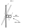
- FIG. It is a top view which shows a mode that the windmill concerning Example 1 rotates centering on a support
- It is detail drawing of the switch 7 which concerns on Example 1.
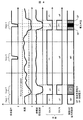
- FIG. It is a figure which shows the time change of the supply destination of auxiliary power supply when abnormality arises in the wind power generation system which concerns on Example 1.
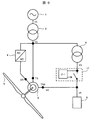
- FIG. It is a single wire connection diagram of the wind power generation system which concerns on Example 2.
- FIG. It is detail drawing of the switch 7 which concerns on Example 2.
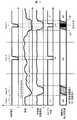
- FIG. It is a figure which shows the time change of the supply destination of auxiliary machine power supply when abnormality arises in the wind power generation system which concerns on Example 2.
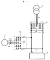
- FIG. 6 is a detailed view of a power conversion device 12 according to a third embodiment. It is a single wire connection diagram of the wind power generation system which concerns on Example 4.
- FIG. 6 is a detailed diagram of a diode rectifier circuit according to Embodiment 4.
- FIG. It is a single wire connection diagram of the wind power generation system which concerns on Example 5.
- FIG. 6 is a detailed view of a power conversion device 12 according to a third embodiment. It is a single wire connection diagram of the wind power generation system which concerns on Example 4.
- FIG. 6 is a detailed diagram of a diode rectifier circuit according to Embodiment 4.
- FIG. It is a single wire connection diagram of the wind power generation system which concerns on Example 5.
- FIG. 6 is a detailed view of a power conversion device 12 according to a third embodiment. It is a single wire connection diagram of the wind power generation system which concerns on Example 4.
- FIG. 6 is a detailed diagram of a diode rectifier circuit according to Embodiment 4.
- Embodiment 1 according to the present invention will be described with reference to FIGS.
- the wind power generation system includes a wind turbine that includes blades 5 and that generates power by receiving wind, an auxiliary machine 8 that is a general term for a control device that controls the wind turbine, and a power system 1.
- a main transformer 2 connected to the side, an auxiliary transformer 6 connected between the main transformer 2 and the auxiliary machine 8, and a switch 7 for switching the side electrically connected to the auxiliary machine 8, It is roughly composed of
- the high voltage (V1) side terminal of the main transformer 2 is connected to the power system 1.
- the low voltage (V2) side terminal of the main transformer 2 is connected to the stator winding terminal TS of the generator 3, the power control device 4, and the high voltage (V2) side terminal of the auxiliary transformer 6.
- An auxiliary machine 8 is connected to the low voltage side terminal of the auxiliary machine transformer 6 via a switch 7.
- the auxiliary machine 8 is also connected to the winding terminal TS ⁇ b> 2 of the auxiliary generator 11 through the switch 7.
- the windmill mainly includes the blade 5 described above, a nacelle 9 on which the generator 3 rotated by the blade 5 is mounted, a support column 10 connected to the nacelle 9 to support the windmill, and an auxiliary generator 11.
- the blade 5 is composed of three blades that are evenly arranged at intervals of 120 degrees when viewed from the front of the windmill.
- the nacelle 9 also stores a device for controlling the rotation angle of the windmill. The rotation angle of the windmill can be rotated 360 degrees in the horizontal direction around the support 10 and the nacelle 9 is rotated according to the wind direction.
- FIG. 2 shows an example of a downwind wind turbine in which the blades 5 are located on the leeward side when viewed from the column 10.
- the downwind wind turbine has a feature that allows free yaw control due to its structure. Free yaw control is to change the rotation angle of the windmill by the wind force without using rotational power. The inclination of each blade of the blade 5 is controlled by a pitch angle control device.
- the auxiliary machine 8 shown in FIG. 1 includes the above-described rotation angle control device and pitch angle control device. Further, the rotor winding terminal TR of the generator 3 is connected to the low voltage side terminal of the main transformer 2 via the power control device 4. The rotor (not shown) of the generator 3 is connected to the wing 5, and the rotator 5 also rotates when the wing 5 rotates upon receiving wind.
- a secondary excitation type AC generator is used as the generator 3 in the present embodiment.
- the power control device 4 is connected to the rotor winding terminal TR of the generator 3, and the power control device 4 is connected to the low voltage (V2) side of the main transformer 2 as described above. That is, an exciting current for power generation operation is conducted from the power system 1 side to the rotor via the power control device 4. Thereby, the magnetic field is changed by rotating the rotor as the blades 5 are rotated by receiving wind, and as a result, an induced electromotive force is generated mainly on the stator side, and the power generation operation is performed.
- the stator winding terminal TS is connected to the power system 1 side via the main transformer 2, and the generated power is sent to the power system side.
- the wind turbine in this embodiment also includes an auxiliary generator 11, and the auxiliary generator 11 receives the wind and the blades 5 rotate, so that the rotor of the auxiliary generator 11 and the rotor of the generator 3 are rotated. Rotate to generate electricity.
- the auxiliary generator 11 has its output terminal TS2 connected to the switch 7.
- the switch 7 includes a measurement transformer 71, a control device 72, a switch circuit 73, a switch circuit 74, and a signal logic inverter 75.
- the terminal voltage TS ⁇ b> 2 of the auxiliary generator 11 is detected by the measuring transformer 71.
- a control device 72 that determines an undervoltage is connected to the secondary side terminal of the measurement transformer 71. Opening / closing of the switch circuit 73 is controlled by an output signal of the control device 72. Further, the logic of the output signal of the control device 72 is inverted by the logic inverter 75, and the opening / closing of the switch circuit 74 is controlled. That is, the switch circuit 73 and the switch circuit 74 operate complementarily.
- the operation as the switch 7 is controlled such that the switch circuit 73 is turned on and the switch circuit 74 is turned off when the voltage V4 is higher than a predetermined voltage.
- the switch circuit 73 is controlled to be off and the switch circuit 74 is controlled to be on.
- the voltage of each part in FIG. 1 there are a main transformer 2 and an auxiliary transformer 6, which handle AC voltages having different voltage amplitudes.
- the voltage V1 between the power system 1 and the main transformer 2 is about 6 to 33 kV. This is a classification of high voltage and extra high voltage in Japan.
- the voltage V2 between the main transformer 2 and the generator 3 is about 600 to 1500V.
- the main transformer 2 plays a role of boosting the generated voltage generated by the generator 3 for power transportation.
- the auxiliary transformer 6 is connected to the low-voltage side terminal of the main transformer 2 and steps down the voltage V2.
- Auxiliary transformer 6 may step down voltage V ⁇ b> 1 between power system 1 and main transformer 2.
- the low voltage side terminal voltage V3 of the auxiliary transformer 6 may be a voltage value required by the auxiliary machine 8, and is therefore a low voltage of 400V or less. It should be noted that the numerical values of the voltages and the voltage ranges described here are shown to assist the understanding of the present specification, and needless to say, do not limit the operating range of the present invention.
- the wind power generation system according to this embodiment performs power generation operation by performing nacelle rotation angle control, pitch angle control, and the like while constantly monitoring the wind speed, the output voltage of the generator, and the like.
- the power supply is switched, so that the state before and after the switching is adjusted. It is possible to switch the power supply without switching, and it is not necessary to adjust the state before and after switching compared to the case where the windmill switches the power supply during power generation operation, so the switching operation can be performed smoothly It becomes like.
- the voltage V1 of the electric power system 1 may decrease for 0.1 second to 1.5 seconds.
- the operation in this case is shown in Case 3 and Case 4 in FIG. Case 3 in FIG. 4 represents an operation in the case where the voltage of the power system 1 is lowered when the windmill is within the range of the wind speed at which the power generation operation is possible.
- the driving power of the auxiliary machine 8 is supplied from the auxiliary generator 11 side and is not affected by the power system 1 side. Accordingly, a power source for driving the auxiliary machine 8 can be secured regardless of the state of the power system 1, and an auxiliary machine power source can be secured even when the power system 1 is abnormal, thereby realizing LVRT. You can also
- Case 4 in FIG. 4 represents an operation when the voltage of the electric power system 1 is further lowered when the wind turbine is outside the range of wind speed at which power generation operation is possible.
- the wind turbine stops the power generation operation, and the driving power of the auxiliary machine 8 changes so as to cover the power system 1 side.
- the power supply source of the auxiliary machine 8 is in a state where the voltage is lowered, and the auxiliary machine 8 is in a stopped state. Therefore, LVRT cannot be realized, but since the wind turbine is outside the range of wind speed at which power generation operation is possible and the wind power generation system is an event that occurs when power generation is stopped, the effect on the power system 1 side is small.
- the auxiliary machine 8 stops when the voltage of the power system 1 decreases in this embodiment.
- the wind turbine rotation angle can be changed by free yaw control even when the auxiliary machine 8 is stopped. it can.
- the auxiliary machine 8 is a general term for control devices that control the windmill. More specifically, the auxiliary machine 8 includes a motor drive device for controlling the rotation angle of the windmill, and a motor for pitch angle control. There are devices with relatively high power consumption such as drive devices and oil pump devices for circulating lubricating oil, and devices with low power consumption such as control circuit boards of control devices. As a power supply voltage of a device that consumes a large amount of power, for example, a voltage requiring 200 to 400 V is often used. In addition, as a power supply for the control board, there are many power supplies with 100 V required.
- Auxiliary equipment 8 composed of the above device group is divided into two groups, and one group can receive power from the power system 1 side, and the other group can receive power from the auxiliary generator 11 It is. If only the control circuit board with low power consumption is used as a device for supplying power from the auxiliary generator 11, the generated power of the auxiliary generator 11 can be reduced, and the generator can be downsized. In addition, if a device with small fluctuations in power consumption is selected as a device that supplies power from the auxiliary generator 11, fluctuations in the received voltage of the auxiliary machine 8 can be suppressed.
- the driving power of the auxiliary machine 8 is controlled to be different according to the output voltage of the auxiliary generator 11, but the windmill can be operated for power generation according to the wind speed instead of the output voltage of the auxiliary generator 11.
- the driving power of the auxiliary machine 8 may be controlled to be different depending on whether the wind speed is within the range or outside the range.
- the auxiliary generator 8 is supplied with power by the auxiliary generator 11, but may be performed by forming an auxiliary winding on the generator 3.
- any alternative can be used as long as it can generate generated power.
- the change in the wind speed is not instantaneous, but gradually changes, so that it can be predicted, and the instantaneous opening / closing operation is not necessarily required. Therefore, as a type of switch, not only a switch that can be opened and closed at high speed (as an example, a thyristor switch) but also an electromagnetic contactor can be used.
- Example 2 according to the present invention will be described with reference to FIGS.
- the power of the auxiliary machine 8 is covered by the power generated by the auxiliary generator 11, and the wind turbine is outside the range of wind speed at which power generation operation is possible.
- the switch 7 is switched to cover the power supply of the auxiliary machine 8 from the power system 1 side, and either the power generated by the auxiliary generator 11 or the power supplied from the power system 1 side of the auxiliary machine 8 is used. I covered the power.
- the power supplied from the power system 1 side is also constantly supplied to the auxiliary machine. I try to connect.
- the power of the auxiliary machine 8 is supplied from the power generated from the auxiliary winding and the power system 1 side. Will be funded by any of the generated power.
- the generator 3 is provided with an auxiliary winding, and the auxiliary winding is wound so as to interlink with the rotating magnetic flux inside the generator 3, and when the excitation current is supplied.
- an alternating voltage is induced at the auxiliary winding terminal TSA.
- the number of turns of the auxiliary winding is determined so that the generated voltage V4 induced at the auxiliary winding terminal TSA becomes a voltage value required by the auxiliary machine 8 (for example, a low voltage of 400 V or less).
- the auxiliary winding is assembled so that the phase of the voltage V4 and the phase of the low-voltage side voltage V3 of the auxiliary transformer 6 are the same.
- the auxiliary winding of the generator 3 may be wound in the slot in which the stator winding of the generator 3 is wound.
- the phases of the alternating voltage induced at the stator winding terminal TS of the generator 3 and the alternating voltage induced at the terminal TSA are matched by winding in the same slot.
- the AC voltage induced at the stator winding terminal TS of the generator 3 needs to be supplied to the power system 1 side, it coincides with the voltage V2 at the low voltage side terminal of the main transformer 2 on average. To be controlled. Therefore, the induced voltage of the auxiliary winding wound in the same slot (the voltage at the terminal TSA) is in phase with the voltage V2.
- the switch 17 includes a measurement transformer 171, a control device 172, a gate driver 173, and a switch circuit 174. Then, the low voltage side terminal voltage V 3 of the auxiliary transformer 6 is detected by the measuring transformer 171 inside the switch 17. A control device 172 that determines an undervoltage is connected to the secondary side terminal of the measurement transformer 171. The output signal of the control device 172 is connected to the gate driver 173. The switch circuit 174 is driven by the gate driver 173. In FIG. 6, the switch circuit 174 shows a thyristor switch in which two thyristor elements are connected in antiparallel. As the operation of the switch 17, the thyristor is turned on when the voltage V3 is normal, and the thyristor is turned off when the voltage V3 falls below a predetermined value.
- control device 172 When the wind turbine is within the range of wind speed at which power generation operation is possible and the power system 1 side is normal, that is, Case 1 in FIG. 7, generated power is generated at the auxiliary winding terminal TSA, and Undervoltage has not occurred in measurement transformer 171, control device 172 does not issue a command to issue an open signal to gate driver 173, and switch circuit 174 is also in a closed state. Therefore, in the above case, the auxiliary winding terminal TSA and the voltage V3 on the power system 1 side are electrically connected to cover the power of the auxiliary machine 8. At this time, as described above, since the AC voltage of the auxiliary winding terminal TSA and the AC voltage supplied from the power system 1 side have the same phase, no current flows between the two, which is efficient. In addition, the power of the auxiliary machine 8 can be covered.
- the current flowing from the power system side to the auxiliary winding terminal TSA can be reduced by electrically disconnecting between the auxiliary winding terminal TSA and the auxiliary machine 8. This can reduce the loss of the windmill system.
- LVRT can be realized as in the first embodiment.
- the LVRT is realized as in the first embodiment.
- the wind turbine is outside the range of the wind speed at which power generation operation is possible and the wind power generation system is an event that occurs when power generation is stopped, the influence on the power system 1 side is small.
- the auxiliary power supply is originally covered by both the power supplied from the auxiliary winding terminal TSA and the power supplied from the power system 1, and the supply from one side is interrupted. Even if it does, it does not change to a new power supply, but since the power supplied originally continues to be supplied, the switching operation can be performed more smoothly than in the first embodiment.
- the auxiliary power supply is covered by both the power supplied from the auxiliary winding terminal TSA and the power supplied from the power system 1 side, so that efficient auxiliary power supply can be performed.
- the auxiliary winding of the generator 3 is wound around the slot in which the stator winding of the generator 3 is wound, and the phase of the auxiliary transformer 6 is phased by the voltage on the primary side and the secondary side. If a method in which the angle is not displaced is selected, the phase of the voltage V4 and the phase of the low-voltage side voltage V3 of the auxiliary transformer 6 can be made the same phase. Therefore, it is possible to efficiently supply auxiliary machine power. Furthermore, since the phase is the same between the auxiliary winding terminal TSA and the power system 1 from the time of power generation without newly using phase control means or the like, the configuration of the wind power generation system can be simplified. Can be obtained, and further advantages can be obtained.
- abnormalities in the power system 1 are often unpredictable and occur in a short time, such as a lightning strike or a ground fault, and the switch 17 requires a high-speed response.
- the thyristor switch is provided in the switch circuit 174, switching at high speed is possible, which is more preferable.
- the electromagnetic contactor can be used in place of the thyristor switch, although the response is lowered.
- a thyristor switch is taken as an example as a switch for high-speed switching, it goes without saying that the switch is not limited to a thyristor switch, and a similar effect can be obtained if it is a switch capable of high-speed response. Not even.
- Example 3 according to the present invention will be described with reference to FIGS.
- an auxiliary generator is separately provided as in the present embodiment, and the power converter 12 is used as a phase control unit. And can be connected to the power system 1 side.
- Other portions are the same as those in the second embodiment, and redundant description is omitted.
- the power converter 12 includes a rectifier circuit 121 that rectifies alternating current on the generator 3 side, a DC link capacitor 122 that is connected to a DC output of the rectifier circuit 121, and a boost chopper circuit 123 that boosts the voltage of the DC link capacitor 122. And a DC link capacitor 124 connected to the output voltage of the step-up chopper circuit 123, and a voltage type inverter circuit 125 that converts the voltage of the DC link capacitor 124 into AC.
- the generated voltage V4 ′ is rectified into a DC voltage in the power converter 12 and converted into an AC voltage again in the voltage type inverter circuit 125. At this time, it is possible to prevent the current from flowing by controlling the AC side voltage of the voltage type inverter circuit 125 so that the voltage V3 matches the voltage amplitude, frequency, and phase.
- the power converter 12 By inserting the power converter 12 between the output terminal TS2 of the auxiliary generator 11 and the auxiliary machine 8, it is not necessary to match the generated voltage and frequency of the auxiliary generator 11 with the voltage V3 of the auxiliary transformer 6. The selection of the auxiliary generator 11 is facilitated. Further, since it is not necessary to match the phase of the AC voltage, the auxiliary generator 11 can be easily installed.
- the power generated by the auxiliary winding or the auxiliary generator is electrically connected to the power system 1 side, and other than the power necessary for driving the auxiliary machine 8.
- the surplus power By supplying the surplus power to the power system 1 side, it is possible to improve the power generation efficiency.
- Example 4 according to the present invention will be described with reference to FIGS.
- the auxiliary machine 8 is connected to the low voltage side terminal of the auxiliary machine transformer 6 through the diode rectifier circuit 13a.
- the output terminal TS2 of the auxiliary generator 11 is connected to the auxiliary machine 8 through the diode rectifier circuit 13b.
- the diode rectifier circuit 13a or 13b includes a three-phase diode rectifier circuit and a smoothing capacitor that smoothes a DC voltage.
- the voltage across the smoothing capacitor is the DC side terminal of the diode rectifier circuit.
- the DC side terminal of the diode rectifier circuit 13a is referred to as a first DC side terminal.
- the DC side terminal of the diode rectifier circuit 13b is referred to as a second DC side terminal.
- the two DC voltage terminals are connected to each other as shown in FIG. 11 and further connected to the power supply terminal of the auxiliary machine 8. In the present embodiment, power is supplied to the auxiliary machine 8 by direct current.
- the higher AC voltage is supplied from the AC side terminal voltage of the diode rectifier circuit 13a or the AC side terminal voltage of the diode rectifier circuit 13b.
- the driving energy of the auxiliary machine 8 can be supplied from the side that is running.
- the magnitude relationship between the low-voltage side voltage V3 of the auxiliary transformer 6 and the generated voltage V4 ′ of the auxiliary generator 11 is large.
- V4 '> V3 (however, V3> 0, V4'> 0)
- the power generation constant of the auxiliary generator is selected so that Since the power generation voltage V4 ′ of the auxiliary generator 11 is high, the diode of the diode rectifier circuit 13a does not have a condition for conducting the diode, and therefore no current flows.
- the driving energy of the auxiliary machine 8 is supplied from the auxiliary generator 11.
- the DC voltage V5 ′ supplied to the auxiliary machine 8 is determined by the voltage V4 ′ having a high voltage value.
- the power generation voltage V4 ′ of the auxiliary generator 11 decreases.
- the magnitude relationship between the voltage V4 'and the voltage V3 is reversed.
- the switching operation is performed when the wind turbine is out of the range of the wind speed at which the power generation operation can be performed, and the power source can be switched without adjusting the state before and after the switching as in the first embodiment. Compared with the case where the wind turbine switches the power source during the power generation operation, it is not necessary to adjust the state before and after the switching, so that the switching operation can be performed smoothly.
- the AC voltage of the auxiliary transformer 6 and the auxiliary generator 11 is converted into a DC voltage by a rectifier circuit, and both are connected to the auxiliary machine 8.
- the switch 7 or the switch 17 it is not necessary to use the switch 7 or the switch 17 as in the above embodiments.
- the measurement transformer 71 and the control device 72 which are necessary for the control of the switch can be omitted.
- the structure of a wind power generation system can be simplified and the reliability of a system can be raised.
- Example 5 according to the present invention will be described with reference to FIG. In each of the above embodiments, the case where an excitation generator is used as the generator 3 has been described. However, a permanent magnet synchronous generator can also be used as in this embodiment.
- the stator winding terminal TS of the generator 3 is connected to the low-voltage side terminal of the main transformer 2 via the power control device 14 and controls the output voltage and the like.
- switches, circuit breakers, arresters, surge absorbing elements, and the like are omitted in order to prevent complication, but this does not mean that these are unnecessary.
- a downwind type windmill has been described as an example.
- the present invention is not intended to limit the content of the invention, but is an upwind type windmill that generates power with its wings facing upwards during power generation operation. Needless to say, this is applicable.
Landscapes
- Engineering & Computer Science (AREA)
- Power Engineering (AREA)
- Business, Economics & Management (AREA)
- Emergency Management (AREA)
- Life Sciences & Earth Sciences (AREA)
- Sustainable Development (AREA)
- Sustainable Energy (AREA)
- Chemical & Material Sciences (AREA)
- Combustion & Propulsion (AREA)
- Mechanical Engineering (AREA)
- General Engineering & Computer Science (AREA)
- Control Of Eletrric Generators (AREA)
Abstract
Description
V4′>V3(ただし、V3>0,V4′>0)
となるように補助発電機の発電定数を選定する。補助発電機11の発電電圧V4′が高いため、ダイオード整流回路13aのダイオードは、ダイオードが導通する条件にならないため、電流が流れない。その結果、補機8の駆動エネルギーは、補助発電機11から供給されることとなる。その際、補機8に供給される直流電圧V5′は、電圧値の高い電圧V4′によって決まる。
V3>V4′
となる。補機変圧器6の低圧側電圧V3が電圧V4′より高くなるため、ダイオード整流回路13bのダイオードは、ダイオードが導通する条件にならず、電流が流れない。その結果、補機8の駆動エネルギーは、電力系統1側から供給される。その際、直流電圧V5′は、電圧値の高い電圧V3によって決まる。
2 主変圧器
3 発電機
4,14 電力制御装置
5 翼
6 補機変圧器
7,17 開閉器
8 補機
9 ナセル
10 支柱
11 補助発電機
12 電力変換装置
13a,13b ダイオード整流回路
33 永久磁石同期発電機
71,171 計測用変圧器
72,172 制御装置
73,74,174 スイッチ回路
75 論理反転器
173 ゲートドライバ
Claims (20)
- 風を受けて発電運転する風車と、該風車を制御する制御装置とを備える風力発電システムの制御方法であって、
前記風車の発電運転中には、電力系統の状態に関わらず、前記風車の発電電力によって前記制御装置を駆動することを特徴とする風力発電システムの制御方法。 - 請求項1に記載の風力発電システムの制御方法であって、
前記風車が発電運転可能な風速範囲内にある場合には、電力系統の状態に関わらず、前記風車の発電電力によって前記制御装置を駆動することを特徴とする風力発電システムの制御方法。 - 請求項1に記載の風力発電システムの制御方法であって、
前記風力発電システムは、発電機を備えており、
該発電機の出力電圧が所定の電圧以上の場合には、電力系統の状態に関わらず、前記風車の発電電力によって前記制御装置を駆動することを特徴とする風力発電システムの制御方法。 - 請求項1に記載の風力発電システムの制御方法であって、
前記風車が発電運転可能な風速範囲外にある場合には、電力系統側から供給される電力によって前記制御装置を駆動することを特徴とする風力発電システムの制御方法。 - 請求項1に記載の風力発電システムの制御方法であって、
前記風力発電システムは、発電機を備えており、
該発電機の出力電圧が所定の電圧未満の場合には、電力系統側から供給される電力によって前記制御装置を駆動することを特徴とする風力発電システムの制御方法。 - 風を受けて発電運転する風車と、該風車を制御する制御装置とを備える風力発電システムの制御方法であって、
前記風車の発電運転中には、前記風車の発電電力及び電力系統側から供給される電力によって前記制御装置を駆動することを特徴とする風力発電システムの制御方法。 - 請求項6に記載の風力発電システムの制御方法であって、
前記風車の発電電力または前記電力系統側から供給される電力の一方が供給されなくなった場合には、他方によって供給される電力によって、前記制御装置を駆動することを特徴とする風力発電システムの制御方法。 - 請求項6または請求項7に記載の風力発電システムの制御方法であって、前記風車の発電電力及び前記電力系統側から供給される電力がいずれも前記制御装置に供給されている場合には、両者の交流電圧の位相が一致していることを特徴とする風力発電システムの制御方法。
- 請求項8に記載の風力発電システムの制御方法であって、前記風車の発電電力及び前記電力系統側から供給される電力がいずれも前記制御装置に供給されている場合には、位相制御手段により両者の交流電圧の位相を一致させることにより、両者が供給する電力の位相は一致していることを特徴とする風力発電システムの制御方法。
- 請求項6ないし請求項9のいずれか一つに記載の風力発電システムの制御方法であって、
前記風車の発電電力のうち、前記制御装置を駆動するための電力以外の剰余電力は、電力系統側に供給されることを特徴とする風力発電システムの制御方法。 - 風を受けて発電運転する風車と、該風車を制御する制御装置とを備える風力発電システムの制御方法であって、
前記制御装置は、常時電力系統側と接続されており、さらに前記風車の発電電力または電力系統側から供給される電力のうち、高い電圧を有する方から供給される電力によって駆動されることを特徴とする風力発電システムの制御方法。 - 請求項11に記載の風力発電システムの制御方法であって、前記風車の発電電力または電力系統側から供給される電力のうち、高い電圧を有する方のみを前記制御装置に供給する電力選定手段を用いることで、前記制御装置は前記風車の発電電力または電力系統側から供給される電力のうち、高い電圧を有する方から供給される電力によって駆動されることを特徴とする風力発電システムの制御方法。
- 風を受けて回転する翼と、該翼の回転力によって回転子を回転させて発電を行う発電機とを有する風車と、該風車を制御する制御装置とを備える風力発電システムであって、
前記発電機には電力系統に供給する電力が発生する固定子巻線と、該固定子巻線が置かれるスロットと同じスロットに補助巻線とが設けられており、
前記主巻線から発生される電力若しくは前記電力系統から供給される電力、及び前記補助巻線から発生される電力は電気的に接続されており、該電気的に接続された電力により前記制御装置を駆動することを特徴とする風力発電システム。 - 風を受けて回転する翼と、該翼の回転力によって回転子を回転させて発電を行う発電機とを有する風車と、該風車を制御する制御装置と、補助発電機とを備える風力発電システムであって、
前記補助発電機により発生される交流電圧は、位相制御手段を介して前記発電機により発生される交流電圧または前記電力系統から供給される交流電圧と電気的に同位相で接続されており、前記制御装置は該電気的に接続された電力により前記制御装置を駆動することを特徴とする風力発電システム。 - 請求項13または請求項14に記載の風力発電システムであって、前記電力系統側と前記電気的に接続された位置との間には、スイッチが設けてあり、該スイッチは前記電力系統側の電圧に応じてスイッチを開閉することを特徴とする風力発電システム。
- 請求項15に記載の風力発電システムであって、前記スイッチはサイリスタスイッチであることを特徴とする風力発電システム。
- 風を受けて回転する翼と、該翼の回転力によって回転子を回転させて発電を行う発電機とを有する風車と、該風車を制御する制御装置と、前記発電機に設けられる補助巻線または補助発電機と、前記発電機に発生する交流電力または前記電力系統から供給される交流電力を直流電力に変換する第一の整流回路と、前記補助巻線または前記補助発電機に発生する交流電力を直流電力に変換する第二の整流回路とを備える風力発電システムであって、
前記第一の整流回路は、前記発電機に発生する交流電圧または前記電力系統から供給される交流電圧が印加される第一の交流側端子と、変換後の直流電圧が印加される第一の直流側端子を備えており、
前記第二の整流回路は、前記補助巻線または前記補助発電機に発生する交流電圧が印加される第二の交流側端子と、変換後の直流電圧が印加される第二の直流側端子を備えており、
前記第一の直流側端子と前記第二の直流側端子とは接続点で電気的に接続されており、
前記制御装置には、該接続点に接続されており、前記第一の交流側端子電圧または前記第二の交流側端子電圧のうち、高い方の電圧を有する側の変換後の直流電力により駆動されることを特徴とする風力発電システム。 - 請求項17に記載の風力発電システムであって、前記整流回路はダイオード整流回路であることを特徴とする風力発電システム。
- 請求項13ないし請求項18のいずれか一つに記載の風力発電システムであって、前記発電機は励磁式の発電機であり、該励磁式の発電機は該励磁式の発電機自身または前記電力系統側と電気的に接続されており、自身の発電電力または前記電力系統側から供給される電力によって励磁電流を賄うことを特徴とする風力発電システム。
- 請求項13ないし請求項18のいずれか一つに記載の風力発電システムであって、前記発電機は永久磁石式の発電機であることを特徴とする風力発電システム。
Priority Applications (4)
| Application Number | Priority Date | Filing Date | Title |
|---|---|---|---|
| EP10854039.4A EP2589799B1 (en) | 2010-06-30 | 2010-06-30 | Wind power generation system and wind power generation system controlling method |
| JP2012522352A JP5672301B2 (ja) | 2010-06-30 | 2010-06-30 | 風力発電システム及び風力発電システムの制御方法 |
| US13/807,709 US9203334B2 (en) | 2010-06-30 | 2010-06-30 | Wind power generator system, and control method for the same |
| PCT/JP2010/004299 WO2012001739A1 (ja) | 2010-06-30 | 2010-06-30 | 風力発電システム及び風力発電システムの制御方法 |
Applications Claiming Priority (1)
| Application Number | Priority Date | Filing Date | Title |
|---|---|---|---|
| PCT/JP2010/004299 WO2012001739A1 (ja) | 2010-06-30 | 2010-06-30 | 風力発電システム及び風力発電システムの制御方法 |
Publications (1)
| Publication Number | Publication Date |
|---|---|
| WO2012001739A1 true WO2012001739A1 (ja) | 2012-01-05 |
Family
ID=45401501
Family Applications (1)
| Application Number | Title | Priority Date | Filing Date |
|---|---|---|---|
| PCT/JP2010/004299 Ceased WO2012001739A1 (ja) | 2010-06-30 | 2010-06-30 | 風力発電システム及び風力発電システムの制御方法 |
Country Status (4)
| Country | Link |
|---|---|
| US (1) | US9203334B2 (ja) |
| EP (1) | EP2589799B1 (ja) |
| JP (1) | JP5672301B2 (ja) |
| WO (1) | WO2012001739A1 (ja) |
Cited By (2)
| Publication number | Priority date | Publication date | Assignee | Title |
|---|---|---|---|---|
| EP2654162A2 (en) * | 2012-04-17 | 2013-10-23 | General Electric Company | Systems and methods for limiting voltage on an auxiliary bus |
| JP2015510083A (ja) * | 2012-03-16 | 2015-04-02 | ヴォッベン プロパティーズ ゲーエムベーハーWobben Properties Gmbh | 利用可能なネット支援なしで風力発電装置を制御する方法 |
Families Citing this family (10)
| Publication number | Priority date | Publication date | Assignee | Title |
|---|---|---|---|---|
| CN103518060A (zh) * | 2011-04-25 | 2014-01-15 | 株式会社日立制作所 | 风力发电系统、利用风力发电系统的装置以及它们的运转方法 |
| US9208529B2 (en) * | 2012-04-06 | 2015-12-08 | International Business Machines Corporation | Smoothing power output from a wind farm |
| CA2898139A1 (en) * | 2013-01-14 | 2014-07-17 | The Governors Of The University Of Alberta | Grid-connected induction machine with controllable power factor |
| JP6200748B2 (ja) | 2013-09-30 | 2017-09-20 | 株式会社日立製作所 | 風力発電設備 |
| US9334749B2 (en) | 2013-10-18 | 2016-05-10 | Abb Technology Ag | Auxiliary power system for turbine-based energy generation system |
| US9614457B2 (en) | 2013-10-18 | 2017-04-04 | Abb Schweiz Ag | Modular thyristor-based rectifier circuits |
| US9577557B2 (en) | 2013-10-18 | 2017-02-21 | Abb Schweiz Ag | Turbine-generator system with DC output |
| DE102015202440A1 (de) * | 2015-02-11 | 2016-08-11 | Robert Bosch Gmbh | Verfahren zum Betreiben eines an eine elektrische Maschine angeschlossenen aktiven Umrichters und Mittel zu dessen Implementierung |
| JP6573923B2 (ja) * | 2017-02-10 | 2019-09-11 | エムエイチアイ ヴェスタス オフショア ウィンド エー/エス | 風力発電施設および風力発電施設の運転方法 |
| US10615608B2 (en) | 2017-04-07 | 2020-04-07 | General Electric Company | Low-wind operation of clustered doubly fed induction generator wind turbines |
Citations (4)
| Publication number | Priority date | Publication date | Assignee | Title |
|---|---|---|---|---|
| US6921985B2 (en) | 2003-01-24 | 2005-07-26 | General Electric Company | Low voltage ride through for wind turbine generators |
| JP2007239599A (ja) | 2006-03-08 | 2007-09-20 | Mitsubishi Heavy Ind Ltd | 風力発電システム、及び風力発電システムの非常用電力供給方法 |
| JP2007252028A (ja) * | 2006-03-14 | 2007-09-27 | Hitachi Ltd | 風力発電水素製造装置 |
| JP2008104286A (ja) * | 2006-10-19 | 2008-05-01 | Nasu Denki Tekko Co Ltd | 風力発電機のバッテリーレス制御方法及び装置 |
Family Cites Families (17)
| Publication number | Priority date | Publication date | Assignee | Title |
|---|---|---|---|---|
| FR2218681B1 (ja) * | 1973-02-21 | 1977-07-29 | Anvar | |
| JP2585409B2 (ja) * | 1988-12-16 | 1997-02-26 | 株式会社日立製作所 | 超電導マグネット装置、その冷却システム及びこれらを備えた磁気浮上走行装置 |
| JPH08322297A (ja) * | 1995-05-24 | 1996-12-03 | Yamaha Motor Co Ltd | 風力発電装置 |
| JP2001190096A (ja) | 1999-10-27 | 2001-07-10 | Mitsubishi Heavy Ind Ltd | 風力発電装置 |
| JP2003129935A (ja) | 2001-10-26 | 2003-05-08 | Mitsubishi Heavy Ind Ltd | 風力発電装置 |
| US7115066B1 (en) * | 2002-02-11 | 2006-10-03 | Lee Paul Z | Continuously variable ratio transmission |
| DE102004024563B4 (de) * | 2004-05-18 | 2008-01-10 | Nordex Energy Gmbh | Verfahren zur Erzeugung von Notstrom für eine Windenergieanlage mit einem Hilfsgenerator |
| DE202004009071U1 (de) * | 2004-05-18 | 2004-08-12 | Nordex Energy Gmbh | Windenergieanlage mit einem Hilfsgenerator |
| AT504818A1 (de) * | 2004-07-30 | 2008-08-15 | Windtec Consulting Gmbh | Triebstrang einer windkraftanlage |
| ES2265771B1 (es) * | 2005-07-22 | 2008-01-16 | GAMESA INNOVATION & TECHNOLOGY, S.L. | Metodo para mantener operativos los componentes de una turbina eolica y una turbina eolica con componentes que permitan el mantenimiento operativo. |
| US7425771B2 (en) | 2006-03-17 | 2008-09-16 | Ingeteam S.A. | Variable speed wind turbine having an exciter machine and a power converter not connected to the grid |
| JP4365394B2 (ja) | 2006-09-20 | 2009-11-18 | 株式会社日立製作所 | 風力発電システムおよびその運転方法 |
| US7709972B2 (en) * | 2007-08-30 | 2010-05-04 | Mitsubishi Heavy Industries, Ltd. | Wind turbine system for satisfying low-voltage ride through requirement |
| JP4759587B2 (ja) * | 2008-04-15 | 2011-08-31 | 株式会社日立エンジニアリング・アンド・サービス | 風力発電所 |
| ES2589908T3 (es) | 2008-09-19 | 2016-11-17 | Vestas Wind Systems A/S | Parque eólico que tiene una fuente de alimentación auxiliar |
| US8258906B2 (en) * | 2009-08-12 | 2012-09-04 | General Electric Company | Superconducting magnetizer |
| JP5401383B2 (ja) | 2010-03-30 | 2014-01-29 | 株式会社日立製作所 | 風力発電システム及びその制御装置 |
-
2010
- 2010-06-30 US US13/807,709 patent/US9203334B2/en not_active Expired - Fee Related
- 2010-06-30 EP EP10854039.4A patent/EP2589799B1/en not_active Not-in-force
- 2010-06-30 WO PCT/JP2010/004299 patent/WO2012001739A1/ja not_active Ceased
- 2010-06-30 JP JP2012522352A patent/JP5672301B2/ja active Active
Patent Citations (4)
| Publication number | Priority date | Publication date | Assignee | Title |
|---|---|---|---|---|
| US6921985B2 (en) | 2003-01-24 | 2005-07-26 | General Electric Company | Low voltage ride through for wind turbine generators |
| JP2007239599A (ja) | 2006-03-08 | 2007-09-20 | Mitsubishi Heavy Ind Ltd | 風力発電システム、及び風力発電システムの非常用電力供給方法 |
| JP2007252028A (ja) * | 2006-03-14 | 2007-09-27 | Hitachi Ltd | 風力発電水素製造装置 |
| JP2008104286A (ja) * | 2006-10-19 | 2008-05-01 | Nasu Denki Tekko Co Ltd | 風力発電機のバッテリーレス制御方法及び装置 |
Non-Patent Citations (1)
| Title |
|---|
| See also references of EP2589799A4 |
Cited By (2)
| Publication number | Priority date | Publication date | Assignee | Title |
|---|---|---|---|---|
| JP2015510083A (ja) * | 2012-03-16 | 2015-04-02 | ヴォッベン プロパティーズ ゲーエムベーハーWobben Properties Gmbh | 利用可能なネット支援なしで風力発電装置を制御する方法 |
| EP2654162A2 (en) * | 2012-04-17 | 2013-10-23 | General Electric Company | Systems and methods for limiting voltage on an auxiliary bus |
Also Published As
| Publication number | Publication date |
|---|---|
| EP2589799A4 (en) | 2014-08-27 |
| JP5672301B2 (ja) | 2015-02-18 |
| EP2589799B1 (en) | 2016-11-02 |
| US9203334B2 (en) | 2015-12-01 |
| EP2589799A1 (en) | 2013-05-08 |
| US20130113212A1 (en) | 2013-05-09 |
| JPWO2012001739A1 (ja) | 2013-08-22 |
Similar Documents
| Publication | Publication Date | Title |
|---|---|---|
| JP5672301B2 (ja) | 風力発電システム及び風力発電システムの制御方法 | |
| US9941687B2 (en) | Methods for operating wind turbine system having dynamic brake | |
| EP2448079B1 (en) | Method and System for Providing Increased Turbine Output for Doubly Fed Induction Generator | |
| JP5836401B2 (ja) | 風力発電システム | |
| DK177553B1 (en) | Wind Turbine with a Primary and a Secondary Generator and Method of Operating such Wind Turbine | |
| WO2012111416A1 (ja) | 風力発電用マトリクスコンバータ装置、風力発電装置、ウィンドファームおよび風車の製造方法 | |
| CA2973534A1 (en) | Method for operating a wind farm | |
| WO2010095240A1 (ja) | 風力発電装置 | |
| EP3893383A1 (en) | System and method for controlling wind turbine converters during high voltage ride through events | |
| US10186996B1 (en) | Methods for operating electrical power systems | |
| US20090021020A1 (en) | Variable speed drive system | |
| US10790770B2 (en) | Methods for operating electrical power systems | |
| US11394324B2 (en) | Selective crowbar response for a power converter to mitigate device failure | |
| JP6453107B2 (ja) | 発電システム | |
| US10823148B2 (en) | Wind turbines and methods | |
| JP5333677B2 (ja) | 風力発電用マトリクスコンバータ装置、風力発電装置、ウィンドファームおよび風車の製造方法 | |
| EP3503381A1 (en) | Methods for providing electrical power to wind turbine components | |
| KR20100114387A (ko) | 선택적 발전방식을 사용하는 풍력 발전기 및 그의 발전 제어방법 |
Legal Events
| Date | Code | Title | Description |
|---|---|---|---|
| 121 | Ep: the epo has been informed by wipo that ep was designated in this application |
Ref document number: 10854039 Country of ref document: EP Kind code of ref document: A1 |
|
| WWE | Wipo information: entry into national phase |
Ref document number: 2012522352 Country of ref document: JP |
|
| REEP | Request for entry into the european phase |
Ref document number: 2010854039 Country of ref document: EP |
|
| WWE | Wipo information: entry into national phase |
Ref document number: 2010854039 Country of ref document: EP |
|
| WWE | Wipo information: entry into national phase |
Ref document number: 13807709 Country of ref document: US |
|
| NENP | Non-entry into the national phase |
Ref country code: DE |