WO2012001847A1 - 空気調和機 - Google Patents
空気調和機 Download PDFInfo
- Publication number
- WO2012001847A1 WO2012001847A1 PCT/JP2011/001979 JP2011001979W WO2012001847A1 WO 2012001847 A1 WO2012001847 A1 WO 2012001847A1 JP 2011001979 W JP2011001979 W JP 2011001979W WO 2012001847 A1 WO2012001847 A1 WO 2012001847A1
- Authority
- WO
- WIPO (PCT)
- Prior art keywords
- refrigerant
- air conditioner
- control means
- alarm
- refrigerant leakage
- Prior art date
- Legal status (The legal status is an assumption and is not a legal conclusion. Google has not performed a legal analysis and makes no representation as to the accuracy of the status listed.)
- Ceased
Links
Images


Classifications
-
- F—MECHANICAL ENGINEERING; LIGHTING; HEATING; WEAPONS; BLASTING
- F24—HEATING; RANGES; VENTILATING
- F24F—AIR-CONDITIONING; AIR-HUMIDIFICATION; VENTILATION; USE OF AIR CURRENTS FOR SCREENING
- F24F1/00—Room units for air-conditioning, e.g. separate or self-contained units or units receiving primary air from a central station
- F24F1/0007—Indoor units, e.g. fan coil units
- F24F1/009—Indoor units, e.g. fan coil units characterised by heating arrangements
-
- F—MECHANICAL ENGINEERING; LIGHTING; HEATING; WEAPONS; BLASTING
- F28—HEAT EXCHANGE IN GENERAL
- F28F—DETAILS OF HEAT-EXCHANGE AND HEAT-TRANSFER APPARATUS, OF GENERAL APPLICATION
- F28F27/00—Control arrangements or safety devices specially adapted for heat-exchange or heat-transfer apparatus
-
- F—MECHANICAL ENGINEERING; LIGHTING; HEATING; WEAPONS; BLASTING
- F24—HEATING; RANGES; VENTILATING
- F24F—AIR-CONDITIONING; AIR-HUMIDIFICATION; VENTILATION; USE OF AIR CURRENTS FOR SCREENING
- F24F11/00—Control or safety arrangements
- F24F11/0001—Control or safety arrangements for ventilation
-
- F—MECHANICAL ENGINEERING; LIGHTING; HEATING; WEAPONS; BLASTING
- F24—HEATING; RANGES; VENTILATING
- F24F—AIR-CONDITIONING; AIR-HUMIDIFICATION; VENTILATION; USE OF AIR CURRENTS FOR SCREENING
- F24F11/00—Control or safety arrangements
- F24F11/30—Control or safety arrangements for purposes related to the operation of the system, e.g. for safety or monitoring
- F24F11/32—Responding to malfunctions or emergencies
- F24F11/36—Responding to malfunctions or emergencies to leakage of heat-exchange fluid
-
- F—MECHANICAL ENGINEERING; LIGHTING; HEATING; WEAPONS; BLASTING
- F24—HEATING; RANGES; VENTILATING
- F24F—AIR-CONDITIONING; AIR-HUMIDIFICATION; VENTILATION; USE OF AIR CURRENTS FOR SCREENING
- F24F11/00—Control or safety arrangements
- F24F11/30—Control or safety arrangements for purposes related to the operation of the system, e.g. for safety or monitoring
- F24F11/46—Improving electric energy efficiency or saving
-
- F—MECHANICAL ENGINEERING; LIGHTING; HEATING; WEAPONS; BLASTING
- F24—HEATING; RANGES; VENTILATING
- F24F—AIR-CONDITIONING; AIR-HUMIDIFICATION; VENTILATION; USE OF AIR CURRENTS FOR SCREENING
- F24F11/00—Control or safety arrangements
- F24F11/50—Control or safety arrangements characterised by user interfaces or communication
- F24F11/52—Indication arrangements, e.g. displays
- F24F11/526—Indication arrangements, e.g. displays giving audible indications
-
- F—MECHANICAL ENGINEERING; LIGHTING; HEATING; WEAPONS; BLASTING
- F24—HEATING; RANGES; VENTILATING
- F24F—AIR-CONDITIONING; AIR-HUMIDIFICATION; VENTILATION; USE OF AIR CURRENTS FOR SCREENING
- F24F11/00—Control or safety arrangements
- F24F11/62—Control or safety arrangements characterised by the type of control or by internal processing, e.g. using fuzzy logic, adaptive control or estimation of values
- F24F11/63—Electronic processing
- F24F11/64—Electronic processing using pre-stored data
-
- F—MECHANICAL ENGINEERING; LIGHTING; HEATING; WEAPONS; BLASTING
- F24—HEATING; RANGES; VENTILATING
- F24F—AIR-CONDITIONING; AIR-HUMIDIFICATION; VENTILATION; USE OF AIR CURRENTS FOR SCREENING
- F24F11/00—Control or safety arrangements
- F24F11/70—Control systems characterised by their outputs; Constructional details thereof
- F24F11/72—Control systems characterised by their outputs; Constructional details thereof for controlling the supply of treated air, e.g. its pressure
- F24F11/74—Control systems characterised by their outputs; Constructional details thereof for controlling the supply of treated air, e.g. its pressure for controlling air flow rate or air velocity
-
- F—MECHANICAL ENGINEERING; LIGHTING; HEATING; WEAPONS; BLASTING
- F24—HEATING; RANGES; VENTILATING
- F24F—AIR-CONDITIONING; AIR-HUMIDIFICATION; VENTILATION; USE OF AIR CURRENTS FOR SCREENING
- F24F11/00—Control or safety arrangements
- F24F11/70—Control systems characterised by their outputs; Constructional details thereof
- F24F11/72—Control systems characterised by their outputs; Constructional details thereof for controlling the supply of treated air, e.g. its pressure
- F24F11/79—Control systems characterised by their outputs; Constructional details thereof for controlling the supply of treated air, e.g. its pressure for controlling the direction of the supplied air
-
- F—MECHANICAL ENGINEERING; LIGHTING; HEATING; WEAPONS; BLASTING
- F24—HEATING; RANGES; VENTILATING
- F24F—AIR-CONDITIONING; AIR-HUMIDIFICATION; VENTILATION; USE OF AIR CURRENTS FOR SCREENING
- F24F11/00—Control or safety arrangements
- F24F11/89—Arrangement or mounting of control or safety devices
-
- F—MECHANICAL ENGINEERING; LIGHTING; HEATING; WEAPONS; BLASTING
- F24—HEATING; RANGES; VENTILATING
- F24F—AIR-CONDITIONING; AIR-HUMIDIFICATION; VENTILATION; USE OF AIR CURRENTS FOR SCREENING
- F24F2110/00—Control inputs relating to air properties
- F24F2110/10—Temperature
-
- F—MECHANICAL ENGINEERING; LIGHTING; HEATING; WEAPONS; BLASTING
- F24—HEATING; RANGES; VENTILATING
- F24F—AIR-CONDITIONING; AIR-HUMIDIFICATION; VENTILATION; USE OF AIR CURRENTS FOR SCREENING
- F24F2140/00—Control inputs relating to system states
Definitions
- the present invention relates to an air conditioner that can improve energy efficiency and safety.
- HFC-based chlorofluorocarbon refrigerants that do not destroy the ozone layer are used as refrigerants for air conditioners and the like.
- this HFC refrigerant has a very high global warming potential and is subject to emission regulations to prevent global warming. Therefore, the use of natural refrigerants such as HFC refrigerants and hydrocarbon refrigerants having a low global warming potential as refrigerants for refrigeration air conditioners has been studied.
- hydrocarbon refrigerants and HFC refrigerants such as R32 which have relatively little influence on global warming, are flammable in nature. Therefore, in order to prevent danger at the time of refrigerant leakage, a primary side cycle using a flammable refrigerant and a secondary side cycle using brine have been used (see, for example, Patent Document 1).
- the conventional air conditioner is configured by a primary side cycle using a combustible refrigerant and a secondary side cycle using brine, and is not a configuration considering energy efficiency.
- the electrical input of the brine circulation pump increased and the energy efficiency decreased.
- an object of the present invention is to provide an air conditioner that can improve energy efficiency and safety when a combustible refrigerant is used as a refrigerant.
- an air conditioner includes a temperature distribution detection unit that detects a temperature distribution of a room, a refrigerant leak detection unit that detects a refrigerant leak, a blow control unit that controls the blow unit, and a blow unit.
- the wind direction control means for controlling the wind direction of the air is provided, and when the refrigerant leakage detection means detects the refrigerant leakage, the air blowing control means and / or the wind direction control means diffuses the leaked refrigerant.
- the occupant and the heat source device can be detected by the temperature distribution detecting means, and the refrigerant can be diffused in a direction different from that of the resident and the heat source device.
- an air conditioner with high energy efficiency can be realized and safety can be improved.
- the installation figure which shows the installation example of the air conditioner in the 1st Embodiment of this invention The block diagram which implement
- movement of the air conditioner in this Embodiment The block diagram which implement
- movement of the air conditioner in this Embodiment The block diagram which implement
- movement of the air conditioner in this Embodiment The figure which shows the relationship between the refrigerant
- the 1st invention controls the temperature direction detection means which detects the temperature distribution of a room, the refrigerant
- the refrigerant leak detection means includes a refrigerant leak alarm means that issues an alarm when the refrigerant leak detection means detects a refrigerant leak, and the refrigerant leak alarm means generates an alarm by voice and / or light. Therefore, the resident can be informed of the abnormality and the danger can be prevented.
- the third invention is the first or second invention, comprising communication means for communicating with another device, and controlling the operation of the other device. Therefore, the ventilation fan or fan having the communication means is operated, the leaked refrigerant is diffused in a direction different from that of the occupants and the heat source device, the heat source device having the communication means is stopped, the refrigerant stays and the refrigerant by the heat source device Can be prevented. Furthermore, an alarm can be generated from an alarm device or the like connected by means of communication with other devices, so that the resident can be notified of the abnormality and the danger can be prevented.
- the storage battery provided in parallel with the main body power supply of the air conditioner as the power supply of the refrigerant leak detection means and the refrigerant leak alarm means, and the energization of the air conditioner are confirmed.
- An energization confirmation circuit and a power supply determination circuit for selecting a power supply device for the refrigerant leak detection means and the refrigerant leak alarm means by a signal from the energization confirmation circuit are provided. Therefore, when refrigerant leakage is detected at the time of operation stop or power outage, power can be supplied from the storage battery and an alarm can be issued, and the danger prevention effect is great.
- At least one of the refrigerant leakage warning unit, the air flow control unit, the wind direction control unit, and the communication unit is selected according to the refrigerant concentration detected by the refrigerant leakage detection unit.
- Control means for controlling one operation is provided. Therefore, even if the concentration is lower than the concentration setting value provided to prevent erroneous detection of refrigerant leakage, the refrigerant leakage alarm means, air blow control means, wind direction control means, and communication means are operated to notify the occupants of the abnormality. Can prevent danger.
- the sixth invention uses a flammable refrigerant in any one of the first to fifth inventions. Therefore, when the flammable refrigerant leaks, it can be diffused in a direction different from that of the occupants and the heat source device, and the stagnation of the refrigerant and the ignition of the flammable refrigerant by the heat source device can be prevented.
- the combustible refrigerant is an HFC type refrigerant, a single refrigerant of a hydrogen fluoride type refrigerant having a carbon double bond, or a mixed refrigerant containing them as a main component. Therefore, when the flammable refrigerant leaks, it can be diffused in a direction different from that of the occupants and the heat source device, and the stagnation of the refrigerant and the ignition of the flammable refrigerant by the heat source device can be prevented. Moreover, the influence on global warming can be reduced.
- the combustible refrigerant is a hydrocarbon single refrigerant or a mixed refrigerant containing them as a main component. Therefore, when the flammable refrigerant leaks, it can be diffused in a direction different from that of the occupants and the heat source device, and the stagnation of the refrigerant and the ignition of the flammable refrigerant by the heat source device can be prevented. Moreover, the influence on global warming can be reduced.
- a single refrigerant or 2 so that the global warming potential is 5 or more and 750 or less, preferably 350 or less, and more preferably 150 or less.
- a refrigerant mixed with three or three components is used. Therefore, when the flammable refrigerant leaks, it can be diffused in a direction different from that of the occupants and the heat source device, and the stagnation of the refrigerant and the ignition of the flammable refrigerant by the heat source device can be prevented. It can also contribute to the prevention of global warming.
- the refrigerating machine oil includes polyoxyalkylene glycols, polyvinyl ethers, poly (oxy) alkylene glycol or a copolymer of a monoether thereof and polyvinyl ether,
- a synthetic oil mainly containing an oxygen-containing compound of any of polyol esters and polycarbonates, a synthetic oil mainly containing alkylbenzenes and ⁇ -olefins, or mineral oil is used. Therefore, ignition of the combustible refrigerant can be prevented. Moreover, it can contribute to the improvement of the reliability of an air conditioner. Below, one Example of the air conditioner of this invention is described. Note that the present invention is not limited to the embodiments.
- FIG. 1 is an installation diagram showing an installation example of an air conditioner according to the first embodiment of the present invention.
- the air conditioner 10 is installed on the wall of a room 1.
- the air conditioner 10 includes a refrigeration cycle circuit including a compressor, an indoor heat exchanger, a decompressor, an outdoor heat exchanger, and the like.
- the refrigeration cycle circuit is filled with flammable refrigerants such as R32, R152a, and R161, and HFC refrigerants such as HFO-1234yf, HFO-1234ze, and HFO-1243zf. Has been.
- the air conditioner 10 includes an alarm sound generating means 11a that emits an alarm sound such as a buzzer when a refrigerant leaks from the air conditioner 10 main body and a refrigerant pipe (not shown), and an alarm light generating means 11b that emits an alarm light.
- the temperature distribution detecting means 12 for detecting the temperature distribution in the room 1 is provided.
- the temperature distribution detecting means 12 uses, for example, a sensor composed of a pyroelectric element that reacts to an object having a high temperature and a Fresnel lens that expands the visual field range for detecting infrared rays, or arranges a large number of pyroelectric elements.
- the temperature distribution in the room 1 is detected using an infrared image sensor that detects a thermal image in the room 1.
- a heat source device 4 such as a stove or a stove
- a ventilation fan 21 such as a fan
- a fan 22 such as a fan
- an alarm device 23 is installed outside the room 1, for example, in another room.
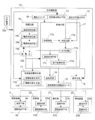
- FIG. 2 is a block diagram for realizing refrigerant leakage control of the air conditioner of the present embodiment.
- the air conditioner 10 is provided with refrigerant leakage detection means 13 for detecting refrigerant leakage in addition to the temperature distribution detection means 12.
- the air conditioner 10 includes a refrigerant leakage warning unit 11, a blowing unit 14 that blows air into the room 1, a wind direction changing blade drive motor 15 that changes the blowing direction from the blowing unit 14 up and down, left and right, and the outside. Communication means 16 for outputting signals.
- the refrigerant leakage warning means 11 is constituted by an alarm sound generating means 11a and / or an alarm light generating means 11b.
- the air blowing means 14 includes a fan such as a cross flow fan or a turbo fan and a motor for driving the fan.
- the air conditioner 10 receives signals from the temperature distribution detection means 12 and the refrigerant leakage detection means 13 and inputs signals to the refrigerant leakage alarm means 11, the blower means 14, the wind direction changing blade drive motor 15, and the communication means 16. Control means 17 for outputting is provided.
- the control means 17 determines the refrigerant leakage based on the output signals of the temperature distribution detection means 12 and the refrigerant leakage detection means 13, the output circuit 17b outputs an operation signal based on the signal of the determination circuit 17a, and the signal of the output circuit 17b.
- An air blowing control means 17c and a wind direction control means 17d are provided.
- the control means 17 includes a storage circuit 17e that stores information necessary for determination by the determination circuit 17a and output information after the determination. That is, the density setting value is stored in the storage circuit 17e as information necessary for the determination.
- the stored concentration setting value includes a normal refrigerant concentration setting value for determining refrigerant leakage, or a low concentration refrigerant concentration setting used for determination when the heat source device 4 is detected by the temperature distribution detection means 12. There is a value.
- the output information after the determination stored in the storage circuit 17e includes the output contents of the refrigerant leakage alarm means 11, the control contents of the air blow control means 17c and the wind direction control means 17d, and the output contents of the communication means 16. is there.
- the output circuit 17 b also outputs a signal to the refrigerant leakage warning unit 11 and the communication unit 16.
- the air blowing control means 17c receives the signal from the temperature distribution detecting means 12 together with the signal from the output circuit 17b, and controls the operation, stop and rotation speed of the air blowing means 14.
- the wind direction control means 17d receives the signal from the temperature distribution detection means 12 together with the signal from the output circuit 17b, operates the wind direction changing blade drive motor 15, and moves the wind direction blown from the blower means 14 up and down. Change to left or right.
- the operation switch 18 operates the refrigerant leakage warning function, but may be linked to an operation switch that operates the normal air conditioning function, and is the same switch as the operation switch that operates the normal air conditioning function. But you can.
- the heat source device 4 includes a communication unit 4a that receives a signal from the communication unit 16, and an operation control unit 4b that stops operation when the communication unit 4a receives a refrigerant leakage signal.
- the ventilation fan 21 includes a communication unit 21a that receives a signal from the communication unit 16, and an operation control unit 21b that performs a refrigerant leakage operation when the communication unit 21a receives a refrigerant leakage signal.
- the electric fan 22 includes a communication unit 22a that receives a signal from the communication unit 16, and an operation control unit 22b that performs a refrigerant leakage operation when the communication unit 22a receives a refrigerant leakage signal.
- the alarm device 23 includes a communication unit 23a that receives a signal from the communication unit 16, and an alarm unit 23b that issues an alarm for refrigerant leakage when the communication unit 23a receives a refrigerant leakage signal.
- FIG. 3 is a flowchart showing the refrigerant leakage detection operation of the air conditioner according to the first embodiment.
- the refrigerant leakage detection means 13 starts detecting refrigerant leakage in step 2.
- the operation switch 18 is interlocked with or the same as the switch for operating the normal air conditioning function, the driving of the compressor, the air blowing means 14 and the like is started, and the operation of the refrigeration cycle is started.
- the output signal from the refrigerant leakage detection means 13 is compared with the refrigerant concentration set value stored in the storage circuit 17e, and the refrigerant leakage is determined by the determination circuit 17a (steps 3 and 4).
- step 3 The determination in step 3 is compared with the low concentration refrigerant concentration set value, and the determination in step 4 is compared with the normal concentration refrigerant concentration set value.
- step 3 when the detected value in the refrigerant leakage detection means 13 is lower than the low concentration set value, it is determined that there is no refrigerant leakage, the process returns to step 2 and the detection by the refrigerant leakage detection means 13 is continued. .
- step 3 when the detected value in the refrigerant leakage detection means 13 is higher than the low concentration set value, it is determined in step 4 whether or not the normal concentration or higher.
- step 4 If it is determined in step 4 that the concentration is equal to or higher than the normal concentration, a refrigerant leak alarm is issued by the refrigerant leak alarm means 11 and an operation command signal is transmitted to other devices (step 5). If it is determined in step 4 that the concentration is less than the normal concentration, the temperature distribution of the room 1 is measured by the temperature distribution detecting means 12 (step 6). Based on the detection in step 6, the determination circuit 17a determines whether the resident 3 is present or whether the heat source device 4 is in operation (step 7). In step 7, when the determination circuit 17a detects the presence of the resident 3 and the heat source device 4 being operated, in step 5, the refrigerant leakage alarm is performed by the refrigerant leakage alarm means 11, and an operation command signal is sent to other devices.
- the output of the blower / wind direction in step 8 is determined.
- the determination circuit 17a in step 7 the position of the resident 3 and the position of the heat source device 4 being operated are also determined.
- the output circuit 17b in step 8 based on the determination result in the determination circuit 17a, an output is generated so that air is blown from the air outlet of the air conditioner 10 in a direction different from the occupant 3 and the heat source device 4 with a predetermined air volume. It is determined.
- the air blowing control means 17c and the wind direction control means 17d are controlled, and the air blowing means 14 and the air direction control means 15 are operated by signals from the air blowing control means 17c and the wind direction control means 17d (step). 9).
- step 7 when the determination circuit 17a detects that the resident 3 does not exist and the heat source device 4 is not operated, in step 5, the refrigerant leakage alarm means 11 performs a refrigerant leakage alarm and operates on other devices. Send command signal.
- the refrigerant leakage alarm by the refrigerant leakage alarm means 11 in step 5 an alarm sound is emitted from the alarm sound generating means 11a, and the LED of the alarm light generating means 11b is blinked.
- the resident 3 is warned of the risk of refrigerant leakage.
- the alarm sound from the alarm sound generating means 11a and the LED blinking in the alarm light generating means 11b are normal refrigerant leakage in step 4, low-concentration refrigerant leakage determined to be a resident or heat source in step 7, and step 7
- the low-concentration refrigerant leaks determined to have no resident or no heat source are different outputs.
- the communication means 16 stops the operation of the heat source device 4 such as a stove or stove having the communication means 4a or cuts off the power supply (Step 10). Further, in transmission to other devices in step 5, the communication unit 16 operates the fan 22 having the communication unit 22a or the ventilation fan 21 having the communication unit 21a, and the leaked refrigerant is transferred to the resident 3 or the heat source device 4. The refrigerant is diffused in a different direction to prevent the refrigerant from staying, the refrigerant from being decomposed by the heat source device 4, and the ignition of the combustible refrigerant (step 11).
- a room different from the room 1 in which the refrigerant leaks is generated by causing the communication means 16 to generate an alarm from the alarm device 23 having the communication means 23a installed in the other room. Even if there is a resident 3 in the room, an abnormality is notified to the resident 3 in another room to prevent danger (step 12).
- the air conditioner 10 having high energy efficiency can be realized, and when the refrigerant leakage occurs, the occupant 3 and the heat source device 4 are detected by the temperature distribution detecting means 12, and the occupant 3 and the heat source are detected.
- the refrigerant can be diffused in a direction different from that of the device 4 to prevent the refrigerant from staying or being decomposed by the heat source device 4. Furthermore, in the case of a flammable refrigerant, the flammable refrigerant can be prevented from being ignited by the heat source device 4.
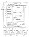
- FIG. 4 is a block diagram for realizing refrigerant leakage control of the air conditioner according to the second embodiment of the present invention.
- the air conditioner 10 shown in FIG. 4 is provided with a storage battery 19b in parallel with the main body power supply 19a.
- the energization circuit 19 in this embodiment includes an energization confirmation circuit 19c that confirms the energization state of the air conditioner 10, and a power determination circuit 19d that selects the main body power supply 19a or the storage battery 19b based on a signal from the energization confirmation circuit 19c.
- a power supply circuit 19e that supplies power using the main body power supply 19a or the storage battery 19b selected by the power supply determination circuit 19d is provided. Electricity is supplied from the storage battery 19b to the energization circuit 19 or the energization confirmation circuit 19c when the main body power supply 19a is not supplied.
- the state where the main body power supply 19a is not supplied is a state where the air conditioner 10 is not connected to a commercial power outlet or a state where power is not supplied to the commercial power source such as a power failure.
- the power supply circuit 19e supplies power to the storage battery 19b to the refrigerant leakage alarm unit 11, the refrigerant leakage detection unit 13, the communication unit 16, and the control unit 17.
- the operation switch 18 in the present embodiment is the same as the switch that performs the operation of the refrigerant leakage alarm function and the operation of the normal air conditioning function or the operation switch that operates the normal air conditioning function. Switch.
- FIG. 5 is a flowchart showing the refrigerant leakage detection operation of the air conditioner according to the second embodiment.
- movement as 1st Embodiment the same step number is attached
- the energization confirmation circuit 19c always confirms the energization state of the air conditioner 10 (step 21).
- the confirmation of the energized state in step 21 detects the supply power from the main body power supply 19a, and detects the state where the air conditioner 10 is not connected to the outlet of the commercial power supply or the state where the commercial power supply is not supplied due to a power failure. To do.
- step 22 it is determined by the energization confirmation circuit 19c whether or not energization from the main body power source 19a is performed. If it is determined in step 22 that the main power source 19a is energized, the instruction on the operation switch 18 is confirmed (step 23). In step 23, when the operation is instructed by the operation switch 18, the operation is started (step 1). That is, driving of the compressor, the air blowing means 14 and the like is started, and the operation of the refrigeration cycle is started. In step 23, when the operation switch 18 is not instructed to operate, the process proceeds to step 2, and the refrigerant leakage detection means 13 starts detecting refrigerant leakage.
- the power supply circuit 19e supplies power by the storage battery 19b (step 24).
- the power supply from the storage battery 19b in step 24 is performed to the refrigerant leak warning means 11, the refrigerant leak detection means 13, the communication means 16, and the control means 17.
- the storage battery operation is started (step 25).
- detection of refrigerant leakage is started by the refrigerant leakage detection means 13 in step 26.
- the output signal from the refrigerant leakage detection means 13 is compared with the refrigerant concentration set value stored in the storage circuit 17e, and the refrigerant leakage is determined by the determination circuit 17a (step 27).
- step 27 when the detection value in the refrigerant leak detection means 13 is lower than the concentration set value, it is determined that there is no refrigerant leak, the process returns to step 26, and the detection by the refrigerant leak detection means 13 is continued.
- step 27 if the detected value in the refrigerant leakage detection means 13 is higher than the concentration set value, the refrigerant leakage alarm is issued by the refrigerant leakage alarm means 11 and an operation command signal is transmitted to other devices (step 5). ).
- the storage battery 19b since the storage battery 19b is provided in parallel with the main body power supply 19a, the storage battery 19b is operated by operating the storage battery 19b when the power to the air conditioner 10 is not turned on or during a power failure.
- the leakage warning means 11 By operating the leakage warning means 11, the communication means 16, and the control means 17, the resident 3 can be notified of the risk of refrigerant leakage.
- the operation switch 18 is not instructed to perform the operation, the refrigerant leakage can be detected and alarmed.
- the storage battery 19b can be used to detect and alarm the refrigerant leakage.
- FIG. 6 is a block diagram for realizing the refrigerant leakage control of the air conditioner in the third embodiment of the present invention
- FIG. 7 is a flowchart showing the refrigerant leakage detection operation of the air conditioner according to the third embodiment. It is. It should be noted that the same functions as those of the configuration according to the embodiment already described are denoted by the same reference numerals and description thereof is omitted. In addition, the same operation as that of the embodiment already described is denoted by the same step number and the description thereof is omitted. As shown in FIG. 6, in this embodiment, a control means power supply actuating means 19f is provided.
- the power supply of the storage battery 19b by the power supply circuit 19e is not limited to the refrigerant leakage alarm means 11, the refrigerant leakage detection means 13, the communication means 16, and the control means 17, but also the temperature distribution detection means 12, This is also performed for the blowing means 14 and the wind direction changing blade drive motor 15. That is, the power supply of the storage battery 19b by the power supply circuit 19e is performed to the air conditioner 10.
- step 23 If it is determined in step 22 that the main power source 19a is energized, the instruction on the operation switch 18 is confirmed (step 23). In step 23, when the operation is instructed by the operation switch 18, the operation is started (step 1). In step 31, if the operation switch 18 is not instructed to operate, the process proceeds to step 2, and the refrigerant leakage detection means 13 starts detecting refrigerant leakage.
- the control means 17 When power is supplied from the storage battery 19b in step 24, the control means 17 is operated by the control means power supply operating means 19f (step 25). The power supply from the storage battery 19b in step 24 is performed to the refrigerant leak detection means 13 and the control means 17.
- step 25 when the control means 17 or the like is operated by the control means power supply operating means 19f, the refrigerant leakage detection means 13 starts detecting refrigerant leakage in step 26.
- step 27 when the detected value in the refrigerant leakage detection means 13 is higher than the concentration set value, the storage battery operation in which the power supply from the storage battery 19b is performed to the indoor unit or the air conditioner 10 is started ( Step 28), go to step 4.
- the refrigerant leakage can be detected and alarmed even when the operation switch 18 is not instructed to operate.
- the main power supply 19a when the main power supply 19a is not energized, power is supplied only to the refrigerant leakage detection means 13 and the control means 17 to detect refrigerant leakage. There is no waste. That is, the power supply from the storage battery 19b is performed to the refrigerant leak warning unit 11, the refrigerant leak detection unit 13, the communication unit 16, and the control unit 17, so that a long-time operation can be performed with limited power.
- FIG. 8 is a block diagram for realizing the refrigerant leakage control of the air conditioner according to the fourth embodiment of the present invention
- FIG. 9 is a flowchart showing the refrigerant leakage detection operation of the air conditioner according to the fourth embodiment. It is. It should be noted that the same functions as those of the configuration according to the embodiment already described are denoted by the same reference numerals and description thereof is omitted. In addition, the same operation as that of the embodiment already described is denoted by the same step number and the description thereof is omitted.
- a control means power supply actuating means 19f is provided. In the present embodiment, the power supply of the storage battery 19b by the power supply circuit 19e is also performed to the refrigerant leakage alarm unit 11, the refrigerant leakage detection unit 13, the communication unit 16, and the control unit 17.
- step 31 If it is determined in step 22 that the main power source 19a is energized, the instruction on the operation switch 18 is confirmed (step 31). In step 31, when the operation is instructed by the operation switch 18, the operation is started (step 1). In step 31, when the operation is not instructed by the operation switch 18, the control means 17 is operated by the control means power supply operating means 19f (step 41). The power supply at this time is performed with respect to the refrigerant leakage warning means 11, the refrigerant leakage detection means 13, the communication means 16, and the control means 17. In step 41, when the control means 17 or the like is operated by the control means power supply actuating means 19f, the refrigerant leakage detection means 13 in step 2 starts detecting refrigerant leakage.
- the power supply from the storage battery 19b in step 24 is performed to the refrigerant leakage alarm unit 11, the refrigerant leakage detection unit 13, the communication unit 16, and the control unit 17.
- the storage battery operation is started (step 25).
- the refrigerant leakage can be detected and alarmed even when the operation switch 18 is not instructed to operate.
- the storage battery 19b can be used to detect and alarm the refrigerant leakage.
- the power supply from the main body power supply 19a is performed to the refrigerant leakage warning unit 11, the refrigerant leakage detection unit 13, the communication unit 16, and the control unit 17, so that standby power can be reduced.
- the storage circuit 17e is provided with a constant refrigerant concentration setting value to prevent erroneous detection of refrigerant leakage. And when the refrigerant
- a plurality of refrigerant concentration setting values are provided in the memory circuit 17e, and the operation of any one of the refrigerant leakage alarm means 11, the air blow control means 17c, the wind direction control means 17d, and the communication means 16 is controlled according to the detected concentration. You may make it do.
- the refrigerant leak alarm means 11 and the air blow control means 16 By operating 17c, the wind direction control means 17d, and the communication means 16, it is possible to notify the occupant 3 of the abnormality and prevent danger.
- the alarm sound generating means 11a is not limited to a signal sound such as a buzzer sound, and a higher risk prevention effect can be obtained if the words stored in the memory of the storage circuit 17e are generated by voice synthesis. be able to. Moreover, you may enable it to select freely the word which the resident 3 considers effective from several words memorize
- HFC refrigerants such as R32, R152a, and R161
- fluorocarbon refrigerants having carbon double bonds such as HFO-1234yf, HFO-1234ze, and HFO-1243zf
- hydrocarbon refrigerants such as propane and isobutane are used.
- a mixed refrigerant may be used.
- R32 with HFO-1234yf as a basic component a two-component mixture such that the global warming potential (GWP) is 5 or more and 750 or less, preferably 5 or more and 350 or less, and more preferably 150 or less, or A refrigerant in which three components are mixed may be used.
- GWP global warming potential
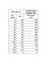
- FIG. 10 is a characteristic diagram showing the global warming potential according to the mixing ratio of the refrigerant in which two components of HFO-1234yf and R32 are mixed.
- R32 is mixed at 51 wt% or less.
- R32 is mixed at 21 wt% or less.
- the refrigerant is a single refrigerant of HFO-1234yf, it becomes GWP4 and shows a very good value.
- the air conditioner 10 since the refrigerating capacity is reduced because the specific volume is larger than the refrigerant mixed with the HFC refrigerant, the air conditioner 10 may be increased in size.
- a fluorocarbon refrigerant having a double bond between carbon and carbon is used as a basic component and a refrigerant mixed with an HFC refrigerant not having a double bond is used, a double bond is formed between carbon and carbon.
- the ratio of the HFC refrigerant including the single refrigerant in the refrigerant to be sealed may be appropriately selected according to conditions such as GWP restrictions.
- the compressor (not shown) constituting the refrigeration cycle of the air conditioner 10 includes polyoxyalkylene glycols, polyvinyl ethers, poly (oxy) alkylene glycols or monoethers thereof and polyvinyl ethers as refrigeration oils.
- the refrigerant leakage warning means is provided in an air conditioner having a temperature distribution detection function at low cost and easily, and is installed in various devices such as a dehumidifier having a refrigeration cycle using a refrigerant and a refrigerator. It is possible and the danger can be avoided.
Landscapes
- Engineering & Computer Science (AREA)
- Mechanical Engineering (AREA)
- General Engineering & Computer Science (AREA)
- Chemical & Material Sciences (AREA)
- Combustion & Propulsion (AREA)
- Physics & Mathematics (AREA)
- Signal Processing (AREA)
- Fuzzy Systems (AREA)
- Mathematical Physics (AREA)
- Human Computer Interaction (AREA)
- Fluid Mechanics (AREA)
- Thermal Sciences (AREA)
- Air Conditioning Control Device (AREA)
Abstract
Description
これによって、冷媒漏洩が発生した時に、温度分布検出手段により居住者や熱源装置を検出し、居住者や熱源装置とは異なる方向へ冷媒を拡散させることができる。
3 居住者
4 熱源装置
10 空気調和機
11 冷媒漏洩警報手段
11a 警報音発生手段
11b 警報光発生手段
12 温度分布検出手段
13 冷媒漏洩検出手段
16 通信手段
17 制御手段
17a 判定回路
17b 出力回路
17c 送風制御手段
17d 風向制御手段
17e 記憶回路
18 運転スイッチ
19 通電回路
19a 本体電源
19b 蓄電池
19c 通電確認回路
19d 電源判定回路
19e 電源供給回路
19f 制御手段電源作動手段
21 通信手段を有する換気扇(他の機器)
22 通信手段を有する扇風機(他の機器)
23 通信手段を有する警報装置(他の機器)
以下に、本発明の空気調和機の一実施例について説明する。なお、この実施の形態によって本発明が限定されるものではない。
図1において、空気調和機10は、部屋1の壁に設置されている。空気調和機10は、圧縮機、室内熱交換器、減圧器、室外熱交換器などから構成される冷凍サイクル回路を備えている。冷凍サイクル回路には、可燃性冷媒であるR32、R152a、R161等のHFC系冷媒や、HFO-1234yf、HFO-1234ze、HFO-1243zf等の炭素の二重結合を持つフッ化炭素系冷媒が封入されている。
また、空気調和機10には、空気調和機10本体や冷媒配管(図示せず)からの冷媒漏洩時に、ブザー等の警報音を発する警報音発生手段11a、警報光を発する警報光発生手段11b、部屋1内の温度分布を検出する温度分布検出手段12を設けている。
温度分布検出手段12は、例えば、温度が高い物体に反応する焦電素子と、赤外線を検出する視野範囲を広げるフレネルレンズで構成されたセンサを用いて、又は多数の焦電素子を配列することで部屋1内の熱画像を検出する赤外線画像センサを用いて、部屋1内の温度分布を検知するようになっている。
部屋1内には、居住者3、ストーブやコンロ等の熱源装置4、換気扇21、及び扇風機22が存在する。また、部屋1の外、例えば、他の部屋には警報装置23が設置されている。
空気調和機10は、温度分布検出手段12の他に冷媒漏洩を検出する冷媒漏洩検出手段13を設けている。また、空気調和機10は、冷媒漏洩警報手段11、部屋1内に空気を送風する送風手段14、送風手段14からの送風方向を上下、左右に変更する風向変更羽根駆動モータ15、外部に対して信号を出力する通信手段16を設けている。冷媒漏洩警報手段11は、警報音発生手段11a及び/又は警報光発生手段11bで構成される。送風手段14は、クロスフローファン、ターボファンなどのファンとこのファンを駆動するモータから構成される。
空気調和機10は、温度分布検出手段12及び冷媒漏洩検出手段13からの信号を入力とし、冷媒漏洩警報手段11、送風手段14、風向変更羽根駆動モータ15、及び通信手段16に対して信号を出力する制御手段17を備えている。
また、記憶回路17eに記憶されている判定後の出力情報には、冷媒漏洩警報手段11での出力内容、送風制御手段17c及び風向制御手段17dでの制御内容、通信手段16での出力内容がある。
出力回路17bは、冷媒漏洩警報手段11及び通信手段16に対しても信号を出力する。送風制御手段17cは、出力回路17bからの信号とともに温度分布検出手段12からの信号を受信して、送風手段14の運転、停止や回転数の制御を行う。また風向制御手段17dは、出力回路17bからの信号とともに温度分布検出手段12からの信号を受信して、風向変更羽根駆動モータ15を動作させ、送風手段14から吹き出される風の方向を上下、左右に変更する。
なお、運転スイッチ18は、冷媒漏洩警報機能を動作させるものであるが、通常の空気調和機能を動作させる運転スイッチと連動したものでもよく、通常の空気調和機能を動作させる運転スイッチと同一のスイッチでもよい。
図3は、第1の実施の形態による空気調和機の冷媒漏洩検知動作を示すフロー図である。
ステップ1において、運転スイッチ18により運転動作が指示されると、ステップ2において、冷媒漏洩検出手段13で冷媒漏洩の検出が開始される。なお、運転スイッチ18が通常の空気調和機能を動作させるスイッチと連動または同一である場合には、圧縮機、送風手段14等の駆動を開始し、冷凍サイクルの運転が開始される。
冷媒漏洩検出手段13からの出力信号が記憶回路17eに記憶されている冷媒濃度設定値と比較されて判定回路17aにより冷媒漏洩が判定される(ステップ3、ステップ4)。ステップ3における判定は低濃度の冷媒濃度設定値と比較され、ステップ4における判定は通常濃度の冷媒濃度設定値と比較される。
ステップ3において、冷媒漏洩検出手段13での検出値が、低濃度設定値よりも低い場合には、冷媒漏洩では無いと判断して、ステップ2に戻り、冷媒漏洩検出手段13による検出を継続する。
ステップ3において、冷媒漏洩検出手段13での検出値が、低濃度設定値よりも高い場合には、ステップ4において、通常濃度以上か否かが判断される。
ステップ4において、通常濃度未満であると判断されると、温度分布検出手段12により部屋1の温度分布を計測する(ステップ6)。
ステップ6における検出を基に判定回路17aでは、居住者3の存在や熱源装置4が運転されているかを判定する(ステップ7)。
ステップ7において、判定回路17aが居住者3の存在や熱源装置4が運転されていることを検出すると、ステップ5において、冷媒漏洩警報手段11による冷媒漏洩警報を行い、他の機器に動作指令信号を送信するとともに、ステップ8における送風・風向の出力が決定される。
ステップ7における判定回路17aでは、居住者3の位置や、運転されている熱源装置4の位置についても判定する。ステップ8における出力回路17bでは、判定回路17aでの判定結果に基づいて、居住者3や熱源装置4とは異なる方向に、所定風量で空気調和機10の吹出口から送風されるように出力が決定される。
ステップ8で決定された出力に基づいて、送風制御手段17c及び風向制御手段17dが制御され、送風制御手段17c及び風向制御手段17dからの信号によって送風手段14及び風向制御手段15が動作する(ステップ9)。
ステップ5における冷媒漏洩警報手段11による冷媒漏洩警報は、警報音発生手段11aから警報音が発せられ、警報光発生手段11bのLEDが点滅される。このように、空気調和機10又は冷媒配管より冷媒が漏れている場合に、居住者3に冷媒漏洩の危険が警報される。
なお、警報音発生手段11aからの警報音や、警報光発生手段11bでのLED点滅は、ステップ4における通常冷媒漏洩、ステップ7における居住者又は熱源有りと判断した低濃度冷媒漏洩、及びステップ7における居住者又は熱源無しと判断した低濃度冷媒漏洩では、それぞれ異なる出力とする。
さらに、ステップ5における他の機器への送信では、通信手段16により、通信手段22aを有する扇風機22や、通信手段21aを有する換気扇21を動作させ、漏洩した冷媒を、居住者3や熱源装置4とは異なる方向へ拡散させ、冷媒の滞留や熱源装置4による冷媒の分解や可燃性冷媒の着火を防止する(ステップ11)。
さらに、ステップ5における他の機器への送信では、通信手段16により、他の部屋に設置された通信手段23aを有する警報装置23から警報を発生させ、冷媒漏洩が発生した部屋1とは異なる部屋に居住者3が居る場合でも、他の部屋に居る居住者3に異常を知らせ、危険を防止する(ステップ12)。
図4に示す空気調和機10には、本体電源19aと並列に蓄電池19bが設けられている。本実施の形態における通電回路19は、空気調和機10の通電状態を確認する通電確認回路19cと、この通電確認回路19cの信号により、本体電源19aか蓄電池19bの選択を行う電源判定回路19dと、電源判定回路19dによって選択された本体電源19a又は蓄電池19bを用いた電源供給を行う電源供給回路19eとが設けられている。
通電回路19又は通電確認回路19cには、本体電源19aが供給されていない状態では蓄電池19bから電力が供給される。ここで、本体電源19aが供給されていない状態とは、空気調和機10が商用電源のコンセントにつながっていない状態や、停電など商用電源に電力供給がされていない状態である。
電源供給回路19eによる蓄電池19bの電力供給は、冷媒漏洩警報手段11、冷媒漏洩検出手段13、通信手段16、及び制御手段17に対して行われる。
なお、本実施の形態における運転スイッチ18は、冷媒漏洩警報機能の動作と、通常の空気調和機能の動作とを連動して行うスイッチ、または、通常の空気調和機能を動作させる運転スイッチと同一のスイッチである。
図5は、第2の実施の形態による空気調和機の冷媒漏洩検知動作を示すフロー図である。なお、第1の実施の形態と同一動作については、同一ステップ番号を付して説明を省略する。
通電確認回路19cは、常に空気調和機10の通電状態を確認している(ステップ21)。ステップ21における通電状態の確認は、本体電源19aからの供給電力を検知し、空気調和機10が商用電源のコンセントにつながっていない状態や、停電による商用電源に電力供給がされていない状態を検知する。
ステップ22では、通電確認回路19cにより、本体電源19aからの通電がなされているか否かを判断する。
ステップ22において、本体電源19aからの通電がなされていると判断された場合には、運転スイッチ18での指示が確認される(ステップ23)。
ステップ23において、運転スイッチ18で運転が指示されている場合には、運転が開始される(ステップ1)。つまり、圧縮機、送風手段14等の駆動を開始し、冷凍サイクルの運転が開始される。ステップ23において、運転スイッチ18で運転が指示されていない場合には、ステップ2に進み、冷媒漏洩検出手段13で冷媒漏洩の検出が開始される。
ステップ24における蓄電池19bからの電力供給は、冷媒漏洩警報手段11、冷媒漏洩検出手段13、通信手段16、及び制御手段17に対して行われる。
ステップ24における蓄電池19bからの電力供給が行われると、蓄電池運転が開始される(ステップ25)。
ステップ25における蓄電池運転が開始されると、ステップ26において、冷媒漏洩検出手段13で冷媒漏洩の検出が開始される。
冷媒漏洩検出手段13からの出力信号が記憶回路17eに記憶されている冷媒濃度設定値と比較されて判定回路17aにより冷媒漏洩が判定される(ステップ27)。
ステップ27において、冷媒漏洩検出手段13での検出値が、濃度設定値よりも低い場合には、冷媒漏洩では無いと判断して、ステップ26に戻り、冷媒漏洩検出手段13による検出を継続する。
ステップ27において、冷媒漏洩検出手段13での検出値が、濃度設定値よりも高い場合には、冷媒漏洩警報手段11による冷媒漏洩警報を行い、他の機器に動作指令信号を送信する(ステップ5)。
また、本実施の形態では、運転スイッチ18で運転が指示されていない場合にも、冷媒漏洩の検出と警報を行うことができる。
特に、本体電源19aからの通電がなされていない場合でも、蓄電池19bを用いて冷媒漏洩の検出と警報を行うことができる。
図6は、本発明の第3の実施の形態における空気調和機の冷媒漏洩制御を実現するブロック図、図7は、第3の実施の形態による空気調和機の冷媒漏洩検知動作を示すフロー図である。なお、既に説明した実施の形態による構成と同一機能には同一符号を付して説明を省略する。また、既に説明した実施の形態と同一動作については、同一ステップ番号を付して説明を省略する。
図6に示すように、本実施の形態では、制御手段電源作動手段19fを備えている。また、本実施の形態では、電源供給回路19eによる蓄電池19bの電力供給は、冷媒漏洩警報手段11、冷媒漏洩検出手段13、通信手段16、及び制御手段17だけでなく、温度分布検出手段12、送風手段14、及び風向変更羽根駆動モータ15に対しても行われる。すなわち、電源供給回路19eによる蓄電池19bの電力供給は空気調和機10に対して行われる。
ステップ22において、本体電源19aからの通電がなされていると判断された場合には、運転スイッチ18での指示が確認される(ステップ23)。
ステップ23において、運転スイッチ18で運転が指示されている場合には、運転が開始される(ステップ1)。ステップ31において、運転スイッチ18で運転が指示されていない場合には、ステップ2に進み、冷媒漏洩検出手段13で冷媒漏洩の検出が開始される。
また、ステップ24における蓄電池19bからの電力供給が行われると、制御手段電源作動手段19fによって制御手段17などを動作させる(ステップ25)。
なお、ステップ24における蓄電池19bからの電力供給は、冷媒漏洩検出手段13及び制御手段17に対して行われる。
ステップ25において、制御手段電源作動手段19fによって制御手段17などが動作すると、ステップ26において、冷媒漏洩検出手段13で冷媒漏洩の検出が開始される。
ステップ27において、冷媒漏洩検出手段13での検出値が、濃度設定値よりも高い場合には、蓄電池19bからの電力供給が室内機または空気調和機10に対して行われる蓄電池運転を開始し(ステップ28)、ステップ4に進む。
特に、本体電源19aからの通電がなされていない場合には、まず、冷媒漏洩検出手段13と制御手段17のみに電力供給を行ない、冷媒漏洩の検出を行うので、限られた蓄電池19bの電力を無駄に消費することがない。つまり、蓄電池19bからの電力供給は、冷媒漏洩警報手段11、冷媒漏洩検出手段13、通信手段16、及び制御手段17に対して行うことで、限られた電力で長時間の運転を行える。
さらに、冷媒漏洩が検出された場合には、室内機または空気調和機10に対して電力供給を行ない、送風手段14や風向変更羽根駆動モータ15により、居住者3や熱源装置4とは異なる方向へ冷媒を拡散させることもできる。
図8は、本発明の第4の実施の形態における空気調和機の冷媒漏洩制御を実現するブロック図、図9は、第4の実施の形態による空気調和機の冷媒漏洩検知動作を示すフロー図である。なお、既に説明した実施の形態による構成と同一機能には同一符号を付して説明を省略する。また、既に説明した実施の形態と同一動作については、同一ステップ番号を付して説明を省略する。
図8に示すように、本実施の形態では、制御手段電源作動手段19fを備えている。なお、本実施の形態では、電源供給回路19eによる蓄電池19bの電力供給は、冷媒漏洩警報手段11、冷媒漏洩検出手段13、通信手段16、及び制御手段17に対しても行われる。
ステップ22において、本体電源19aからの通電がなされていると判断された場合には、運転スイッチ18での指示が確認される(ステップ31)。
ステップ31において、運転スイッチ18で運転が指示されている場合には、運転が開始される(ステップ1)。ステップ31において、運転スイッチ18で運転が指示されていない場合には、制御手段電源作動手段19fによって制御手段17などを動作させる(ステップ41)。なお、この際の電力供給は、冷媒漏洩警報手段11、冷媒漏洩検出手段13、通信手段16、及び制御手段17に対して行われる。
ステップ41において、制御手段電源作動手段19fによって制御手段17などが動作すると、ステップ2における冷媒漏洩検出手段13で冷媒漏洩の検出が開始される。
なお、ステップ24における蓄電池19bからの電力供給は、冷媒漏洩警報手段11、冷媒漏洩検出手段13、通信手段16、及び制御手段17に対して行われる。
ステップ24における蓄電池19bからの電力供給が行われると、蓄電池運転が開始される(ステップ25)。
特に、本体電源19aからの通電がなされていない場合でも、蓄電池19bを用いて冷媒漏洩の検出と警報を行うことができる。
また、本体電源19aからの電力供給は、冷媒漏洩警報手段11、冷媒漏洩検出手段13、通信手段16、及び制御手段17に対して行うことで、待機電力の低減を図ることができる。
なお、警報音発生手段11aは、ブザー音等の信号音に限らず、記憶回路17eのメモリに記憶された言葉を、音声合成による声で発生するようにすれば、より高い危険防止効果を得ることができる。又、予め記憶された複数の言葉の中から居住者3が有効と考える言葉を自由に選択できるようにしてもよい。
例えば、HFO-1234yfを基本成分にR32を、地球温暖化係数(GWP)が5以上で750以下、望ましくは5以上で350以下、さらに望ましくは150以下、となるようにそれぞれ2成分混合、もしくは3成分混合した冷媒であってもよい。
また、冷媒をHFO-1234yfの単一冷媒とした時にはGWP4となり、極めて良好な値を示す。しかしながら、HFC系冷媒と混合した冷媒に比べて比容積が大きいことなどから冷凍能力が低くなるため、空気調和機10が大型化する恐れがある。換言すれば、炭素と炭素間に2重結合を有するフッ化炭素系冷媒を基本成分とし、2重結合を有しないHFC系冷媒を混合した冷媒を用いれば、炭素と炭素間に2重結合を有するフッ化炭素系冷媒の単一冷媒と比較して、冷凍能力などの所定の特性を改善して冷媒として使用しやすくすることができる。したがって、封入する冷媒中の、単一冷媒を含めたHFC系冷媒の割合は、GWPの制限などの条件に応じて適宜選択すればよい。
また、空気調和機10の冷凍サイクルを構成する圧縮機(図示せず)には、冷凍機油として、ポリオキシアルキレングリコール類、ポリビニルエーテル類、ポリ(オキシ)アルキレングリコールまたはそのモノエーテルとポリビニルエーテルの共重合体、ポリオールエステル類、またはポリカーボネート類のいずれかの含酸素化合物を主成分とする合成油、アルキルベンゼン類またはαオレフィン類を主成分とする合成油、または、鉱油を用い、空気調和機10の信頼性の向上に貢献することができる。
Claims (10)
- 部屋の温度分布を検出する温度分布検出手段と、冷媒漏洩を検出する冷媒漏洩検出手段と、送風手段と、前記送風手段を制御する送風制御手段と、前記送風手段の風向を制御する風向制御手段とを備え、前記冷媒漏洩検出手段が冷媒漏洩を検出した時に前記送風制御手段かつ/または前記風向制御手段により、漏洩した冷媒を拡散させることを特徴とする空気調和機。
- 前記冷媒漏洩検出手段が冷媒漏洩を検出した時に警報を発する冷媒漏洩警報手段を備え、前記冷媒漏洩警報手段は、音声かつ/または光で警報を発生させることを特徴とする請求項1に記載の空気調和機。
- 他の機器と通信する通信手段を備え、前記他の機器の動作を制御することを特徴とする請求項1または2に記載の空気調和機。
- 前記冷媒漏洩検出手段および前記冷媒漏洩警報手段の電源として前記空気調和機の本体電源と並列に設けられた蓄電池と、前記空気調和機の通電を確認する通電確認回路と、前記通電確認回路の信号により前記冷媒漏洩検出手段および前記冷媒漏洩警報手段の電源装置の選択を行う電源判定回路とを設けることを特徴とする請求項2または3に記載の空気調和機。
- 前記冷媒漏洩検出手段により検出された冷媒濃度に応じて、前記冷媒漏洩警報手段、前記送風制御手段、前記風向制御手段、前記通信手段の少なくとも1つの動作を制御する制御手段を設けることを特徴とする請求項1~4のいずれか1項に記載の空気調和機。
- 可燃性冷媒を使用したことを特徴とする請求項1~5のいずれか1項に記載の空気調和機。
- 前記可燃性冷媒はHFC系冷媒または炭素の二重結合を持つフッ化水素系冷媒の単一冷媒またはそれらを主成分とする混合冷媒であることを特徴とする請求項6に記載の空気調和機。
- 前記可燃性冷媒は炭化水素の単一冷媒またはそれらを主成分とする混合冷媒であることを特徴とする請求項6に記載の空気調和機。
- 前記可燃性冷媒として、地球温暖化係数が5以上、750以下となるように、望ましくは350以下、さらに望ましくは150以下となるように、前記単一冷媒または2成分混合もしくは3成分混合した冷媒を用いたことを特徴とする請求項7または8に記載の空気調和機。
- 冷凍機油として、ポリオキシアルキレングリコール類、ポリビニルエーテル類、ポリ(オキシ)アルキレングリコールまたはそのモノエーテルとポリビニルエーテルの共重合体、ポリオールエステル類、またはポリカーボネート類のいずれかの含酸素化合物を主成分とする合成油、アルキルベンゼン類またはαオレフィン類を主成分とする合成油、または、鉱油を用いることを特徴とする請求項1~9のいずれか1項に記載の空気調和機。
Priority Applications (4)
| Application Number | Priority Date | Filing Date | Title |
|---|---|---|---|
| AU2011272701A AU2011272701B2 (en) | 2010-07-02 | 2011-04-01 | Air conditioner |
| US13/807,105 US20130098576A1 (en) | 2010-07-02 | 2011-04-01 | Air conditioner |
| CN201180032871.6A CN102971596B (zh) | 2010-07-02 | 2011-04-01 | 空气调节机 |
| EP11800326.8A EP2589900B1 (en) | 2010-07-02 | 2011-04-01 | Air conditioner |
Applications Claiming Priority (2)
| Application Number | Priority Date | Filing Date | Title |
|---|---|---|---|
| JP2010-151770 | 2010-07-02 | ||
| JP2010151770A JP2012013348A (ja) | 2010-07-02 | 2010-07-02 | 空気調和機 |
Publications (1)
| Publication Number | Publication Date |
|---|---|
| WO2012001847A1 true WO2012001847A1 (ja) | 2012-01-05 |
Family
ID=45401599
Family Applications (1)
| Application Number | Title | Priority Date | Filing Date |
|---|---|---|---|
| PCT/JP2011/001979 Ceased WO2012001847A1 (ja) | 2010-07-02 | 2011-04-01 | 空気調和機 |
Country Status (6)
| Country | Link |
|---|---|
| US (1) | US20130098576A1 (ja) |
| EP (1) | EP2589900B1 (ja) |
| JP (1) | JP2012013348A (ja) |
| CN (1) | CN102971596B (ja) |
| AU (1) | AU2011272701B2 (ja) |
| WO (1) | WO2012001847A1 (ja) |
Cited By (7)
| Publication number | Priority date | Publication date | Assignee | Title |
|---|---|---|---|---|
| CN103322641A (zh) * | 2012-03-21 | 2013-09-25 | 广东美芝精密制造有限公司 | 使用可燃性冷媒空调器的安全控制方法 |
| CN103673207A (zh) * | 2012-09-24 | 2014-03-26 | 珠海格力电器股份有限公司 | 碳氢冷媒浓度控制系统及碳氢空调及控制冷媒浓度的方法 |
| JP2016090110A (ja) * | 2014-10-31 | 2016-05-23 | ダイキン工業株式会社 | 空気調和機 |
| WO2016132906A1 (ja) * | 2015-02-18 | 2016-08-25 | ダイキン工業株式会社 | 空調システム |
| CN106052038A (zh) * | 2016-07-04 | 2016-10-26 | 珠海格力电器股份有限公司 | 空调系统、空调控制方法和装置 |
| JP2016211762A (ja) * | 2015-04-30 | 2016-12-15 | ダイキン工業株式会社 | 空調換気システム |
| JP2022087617A (ja) * | 2020-12-01 | 2022-06-13 | パナソニックIpマネジメント株式会社 | 空気調和システム |
Families Citing this family (92)
| Publication number | Priority date | Publication date | Assignee | Title |
|---|---|---|---|---|
| CN103392102B (zh) * | 2011-09-14 | 2016-08-10 | 松下电器产业株式会社 | 空气调节机 |
| WO2013145014A1 (ja) * | 2012-03-29 | 2013-10-03 | 三菱電機株式会社 | 室内機及びそれを備えた空気調和装置 |
| JPWO2013145012A1 (ja) * | 2012-03-29 | 2015-08-03 | 三菱電機株式会社 | 室外機及びその室外機を備えた空気調和装置 |
| WO2013145013A1 (ja) * | 2012-03-29 | 2013-10-03 | 三菱電機株式会社 | 分流コントローラー及びそれを備えた空気調和装置 |
| WO2013145012A1 (ja) * | 2012-03-29 | 2013-10-03 | 三菱電機株式会社 | 室外機及びその室外機を備えた空気調和装置 |
| JP2014035171A (ja) * | 2012-08-10 | 2014-02-24 | Mitsubishi Electric Corp | 空気調和機、空気調和方法及びプログラム |
| JP5734263B2 (ja) * | 2012-11-16 | 2015-06-17 | 三菱電機株式会社 | 空気調和機の室内機 |
| JP6164400B2 (ja) * | 2013-02-28 | 2017-07-19 | アイシン精機株式会社 | エンジン駆動式空調装置 |
| JP2015021683A (ja) * | 2013-07-22 | 2015-02-02 | パナソニック株式会社 | 冷凍装置 |
| CN105452784B (zh) * | 2013-08-01 | 2017-06-13 | 三菱电机株式会社 | 热源单元 |
| JP5812081B2 (ja) * | 2013-11-12 | 2015-11-11 | ダイキン工業株式会社 | 室内機 |
| JP2015094513A (ja) * | 2013-11-12 | 2015-05-18 | ダイキン工業株式会社 | 空気調和機 |
| JP2015117931A (ja) * | 2013-11-14 | 2015-06-25 | ダイキン工業株式会社 | 室内機 |
| JP6293557B2 (ja) * | 2014-04-01 | 2018-03-14 | 東芝キヤリア株式会社 | 冷凍サイクル装置 |
| JP2016003783A (ja) | 2014-06-13 | 2016-01-12 | 三菱電機株式会社 | ヒートポンプ装置 |
| US10060645B2 (en) | 2014-06-19 | 2018-08-28 | Mitsubishi Electric Corporation | Indoor unit of air-conditioning apparatus and air-conditioning apparatus including the indoor unit |
| JP6302809B2 (ja) * | 2014-09-25 | 2018-03-28 | 東芝キヤリア株式会社 | 冷凍サイクル装置 |
| JP6408324B2 (ja) * | 2014-09-29 | 2018-10-17 | 日立ジョンソンコントロールズ空調株式会社 | 空気調和機の室内機 |
| JP6412395B2 (ja) * | 2014-10-14 | 2018-10-24 | 日立ジョンソンコントロールズ空調株式会社 | 空気調和機の室内機 |
| JP5987887B2 (ja) | 2014-10-31 | 2016-09-07 | ダイキン工業株式会社 | 空気調和機の室内機 |
| JP6020534B2 (ja) | 2014-10-31 | 2016-11-02 | ダイキン工業株式会社 | 空気調和機 |
| WO2016079801A1 (ja) | 2014-11-18 | 2016-05-26 | 三菱電機株式会社 | 空気調和装置 |
| CN107003049B (zh) * | 2014-11-25 | 2020-01-17 | 三菱电机株式会社 | 冷冻循环装置 |
| JP2016109356A (ja) | 2014-12-05 | 2016-06-20 | ダイキン工業株式会社 | 空気調和機 |
| JP6431366B2 (ja) * | 2014-12-26 | 2018-11-28 | 日立ジョンソンコントロールズ空調株式会社 | 空気調和システム |
| JP6528446B2 (ja) * | 2015-02-18 | 2019-06-12 | ダイキン工業株式会社 | 空気調和装置 |
| NZ733257A (en) * | 2015-03-26 | 2019-06-28 | Mitsubishi Electric Corp | Indoor unit of air-conditioning apparatus |
| JP6222252B2 (ja) * | 2015-03-30 | 2017-11-01 | ダイキン工業株式会社 | 空気調和装置の室内機 |
| JP6565273B2 (ja) * | 2015-03-31 | 2019-08-28 | ダイキン工業株式会社 | 冷凍装置 |
| JP6582496B2 (ja) * | 2015-03-31 | 2019-10-02 | ダイキン工業株式会社 | 空調室内ユニット |
| JP6497195B2 (ja) * | 2015-04-28 | 2019-04-10 | ダイキン工業株式会社 | 空調装置 |
| WO2017002216A1 (ja) * | 2015-06-30 | 2017-01-05 | 三菱電機株式会社 | 冷媒漏洩検知装置 |
| JP6498289B2 (ja) * | 2015-06-30 | 2019-04-10 | 三菱電機株式会社 | 冷凍サイクルシステム |
| JP6463478B2 (ja) * | 2015-07-17 | 2019-02-06 | 三菱電機株式会社 | 空気調和装置 |
| WO2017026014A1 (ja) * | 2015-08-07 | 2017-02-16 | 三菱電機株式会社 | 冷凍サイクル装置 |
| JP6168113B2 (ja) * | 2015-08-11 | 2017-07-26 | ダイキン工業株式会社 | 空調室内機 |
| JP6613734B2 (ja) | 2015-09-04 | 2019-12-04 | ダイキン工業株式会社 | 空調システム |
| JP6637702B2 (ja) * | 2015-09-08 | 2020-01-29 | 日立ジョンソンコントロールズ空調株式会社 | 空気調和システム |
| JP6580160B2 (ja) * | 2015-12-15 | 2019-09-25 | 三菱電機株式会社 | 除湿機 |
| CN108474580A (zh) * | 2016-01-19 | 2018-08-31 | 开利公司 | 用于制冷剂检测的传感器阵列 |
| EP3428555B1 (en) * | 2016-03-10 | 2022-08-31 | Mitsubishi Electric Corporation | Refrigeration cycle device |
| CN209101501U (zh) * | 2016-03-28 | 2019-07-12 | 三菱电机株式会社 | 空调机的室内机 |
| WO2017175300A1 (ja) * | 2016-04-05 | 2017-10-12 | 三菱電機株式会社 | 空気調和装置 |
| JP6584649B2 (ja) * | 2016-04-19 | 2019-10-02 | 三菱電機株式会社 | 空気調和機 |
| EP3460346A4 (en) * | 2016-05-17 | 2019-05-08 | Mitsubishi Electric Corporation | AIR CONDITIONER |
| WO2018020992A1 (ja) * | 2016-07-28 | 2018-02-01 | パナソニックIpマネジメント株式会社 | 圧縮機 |
| JP6380500B2 (ja) * | 2016-10-17 | 2018-08-29 | ダイキン工業株式会社 | 冷凍装置 |
| JP6636173B2 (ja) | 2016-11-22 | 2020-01-29 | 三菱電機株式会社 | 空気調和装置及び空気調和システム |
| JP7105538B2 (ja) * | 2017-01-16 | 2022-07-25 | ダイキン工業株式会社 | 空気調和装置の室内ユニット |
| WO2018154652A1 (ja) * | 2017-02-22 | 2018-08-30 | 三菱電機株式会社 | リモコン装置、空調機及び空調システム |
| CN110382966B (zh) | 2017-03-10 | 2021-04-09 | 三菱电机株式会社 | 制冷剂检测装置 |
| JP6289702B2 (ja) * | 2017-03-23 | 2018-03-07 | 三菱電機株式会社 | 空気調和装置 |
| JP6477767B2 (ja) | 2017-03-31 | 2019-03-06 | ダイキン工業株式会社 | 冷凍装置 |
| ES2968240T3 (es) * | 2017-05-24 | 2024-05-08 | Mitsubishi Electric Corp | Sistema de acondicionamiento de aire |
| JP7176175B2 (ja) * | 2017-06-30 | 2022-11-22 | 三菱電機株式会社 | 空気調和機 |
| US10514176B2 (en) | 2017-12-01 | 2019-12-24 | Johnson Controls Technology Company | Systems and methods for refrigerant leak management |
| JP6906685B2 (ja) * | 2018-03-13 | 2021-07-21 | 三菱電機株式会社 | 空気調和システム |
| JP7009624B2 (ja) * | 2018-05-21 | 2022-02-10 | 三菱電機株式会社 | 空気調和機および空気調和機の梱包セット |
| JP7256248B2 (ja) * | 2018-05-21 | 2023-04-11 | 三菱電機株式会社 | 空気調和機の梱包セット |
| US11879650B2 (en) * | 2018-08-06 | 2024-01-23 | Daikin Industries, Ltd. | Air conditioning system |
| CN108954666A (zh) * | 2018-08-21 | 2018-12-07 | 珠海格力电器股份有限公司 | 一种机组、隔离装置及冷媒泄漏处理方法、装置 |
| WO2020055685A1 (en) * | 2018-09-10 | 2020-03-19 | Carrier Corporation | Gas monitoring apparatus and method |
| JP2020051736A (ja) * | 2018-09-28 | 2020-04-02 | ダイキン工業株式会社 | 熱負荷処理システム |
| US11959675B2 (en) | 2018-11-28 | 2024-04-16 | Mitsubishi Electric Corporation | Air-conditioning apparatus |
| JP2019070518A (ja) * | 2019-01-08 | 2019-05-09 | 三菱重工サーマルシステムズ株式会社 | 室内機ユニットおよび空気調和装置 |
| EP3896356B1 (en) * | 2019-01-18 | 2023-01-04 | Mitsubishi Electric Corporation | Air conditioner and control method |
| CN110107984A (zh) * | 2019-04-29 | 2019-08-09 | 广东美的制冷设备有限公司 | 空调的冷媒泄漏控制方法、系统及空调 |
| CN110173812A (zh) * | 2019-05-29 | 2019-08-27 | 广东美的制冷设备有限公司 | 空调器及空调器的控制方法、装置 |
| WO2020220667A1 (zh) * | 2019-04-29 | 2020-11-05 | 广东美的制冷设备有限公司 | 空调器及空调器的控制方法、装置 |
| CN110044033A (zh) * | 2019-04-29 | 2019-07-23 | 广东美的制冷设备有限公司 | 空调的制冷剂泄漏检测方法、系统及空调 |
| CN110057055A (zh) * | 2019-04-30 | 2019-07-26 | 广东美的制冷设备有限公司 | 空调器及其控制方法与装置 |
| US11662109B2 (en) | 2019-06-05 | 2023-05-30 | Carrier Corporation | Enclosure for gas detector |
| US11435101B2 (en) | 2019-09-26 | 2022-09-06 | Rheem Manufacturing Company | Air mover refrigerant leak detection and risk mitigation |
| JP7157722B2 (ja) | 2019-09-30 | 2022-10-20 | ダイキン工業株式会社 | 空調換気システム |
| JP2021081139A (ja) * | 2019-11-20 | 2021-05-27 | パナソニックIpマネジメント株式会社 | 空調システム |
| JP7439517B2 (ja) * | 2020-01-07 | 2024-02-28 | 三菱電機株式会社 | 送風装置及び送風システム |
| JP7403079B2 (ja) * | 2020-02-20 | 2023-12-22 | パナソニックIpマネジメント株式会社 | 空気調和装置 |
| EP3875861B1 (en) * | 2020-03-06 | 2023-05-17 | Daikin Industries, Ltd. | Air-conditioner, air-conditioning system, and method for monitoring air-conditioner |
| JP7474923B2 (ja) * | 2020-06-25 | 2024-04-26 | パナソニックIpマネジメント株式会社 | 空気調和機 |
| JP7641506B2 (ja) * | 2021-02-15 | 2025-03-07 | パナソニックIpマネジメント株式会社 | 空気調和機 |
| EP4148358A1 (en) | 2021-09-08 | 2023-03-15 | Carrier Corporation | Refrigerated display cabinet |
| CN115143591B (zh) * | 2022-06-30 | 2024-03-01 | 海信空调有限公司 | 空调 |
| CN115313598A (zh) * | 2022-07-15 | 2022-11-08 | 广东美的白色家电技术创新中心有限公司 | 制冷剂泄漏检测单元的供电方法及装置 |
| CN115313602B (zh) * | 2022-07-15 | 2026-03-06 | 广东美的白色家电技术创新中心有限公司 | 制冷剂泄漏检测单元的供电方法及装置 |
| JP7557156B2 (ja) * | 2022-09-30 | 2024-09-27 | ダイキン工業株式会社 | 冷凍サイクル装置の管理装置 |
| USD1115569S1 (en) | 2022-11-28 | 2026-03-03 | Danfoss A/S | Gas detection sensor |
| USD1119637S1 (en) | 2023-02-09 | 2026-03-24 | Danfoss A/S | Gas detection sensor |
| USD1115570S1 (en) | 2023-08-15 | 2026-03-03 | Danfoss A/S | Gas detection sensor |
| US12504190B2 (en) * | 2023-10-17 | 2025-12-23 | Trane International Inc. | Air conditioning unit with a leak ventilation inducer |
| US12516839B2 (en) * | 2023-10-17 | 2026-01-06 | Trane International Inc. | Ventilation air valve, and air conditioning unit thereof |
| JP2026000652A (ja) * | 2024-06-18 | 2026-01-06 | 日本キヤリア株式会社 | 冷媒漏えい検知システム |
| US20260052659A1 (en) * | 2024-08-15 | 2026-02-19 | Vertiv Corporation | A2l gas sensor service backup safety |
Citations (7)
| Publication number | Priority date | Publication date | Assignee | Title |
|---|---|---|---|---|
| JPH07159010A (ja) * | 1993-12-09 | 1995-06-20 | Matsushita Electric Ind Co Ltd | 空気調和機 |
| JPH1035266A (ja) | 1996-07-25 | 1998-02-10 | Zexel Corp | 自動車用空調装置 |
| JP2000200395A (ja) * | 1999-01-07 | 2000-07-18 | Matsushita Electric Ind Co Ltd | 防火システム |
| JP2002240535A (ja) * | 2001-02-13 | 2002-08-28 | Sanyo Electric Co Ltd | 車内監視システム |
| JP2005003220A (ja) * | 2003-06-09 | 2005-01-06 | Sanden Corp | 空調冷媒ガス漏洩警報装置 |
| JP2005009857A (ja) * | 1998-07-01 | 2005-01-13 | Daikin Ind Ltd | 冷凍装置および冷媒漏洩検出方法 |
| JP2007538115A (ja) * | 2004-04-29 | 2007-12-27 | ハネウェル・インターナショナル・インコーポレーテッド | テトラフルオロプロペンおよびハイドロフルオロカーボンの共沸混合物様組成物 |
Family Cites Families (25)
| Publication number | Priority date | Publication date | Assignee | Title |
|---|---|---|---|---|
| US3778634A (en) * | 1973-05-18 | 1973-12-11 | Foxboro Co | Power supply with battery backup |
| US4671458A (en) * | 1985-02-25 | 1987-06-09 | Kabushiki Kaisha Toshiba | Air conditioning apparatus |
| US5684463A (en) * | 1994-05-23 | 1997-11-04 | Diercks; Richard Lee Roi | Electronic refrigeration and air conditioner monitor and alarm |
| US5918475A (en) * | 1995-10-11 | 1999-07-06 | Denso Corporation | Air conditioning apparatus for vehicle, using a flammable refrigerant |
| JPH09318208A (ja) * | 1996-06-03 | 1997-12-12 | Daikin Ind Ltd | 可燃性冷媒を用いた冷凍装置 |
| JPH09324928A (ja) * | 1996-06-05 | 1997-12-16 | Daikin Ind Ltd | 可燃性冷媒を用いた空気調和機 |
| KR100509153B1 (ko) * | 1997-04-17 | 2005-10-24 | 산요덴키가부시키가이샤 | 공기조화기 |
| JPH1137619A (ja) * | 1997-07-16 | 1999-02-12 | Daikin Ind Ltd | 自然冷媒を用いた空気調和装置 |
| JPH11230648A (ja) * | 1998-02-13 | 1999-08-27 | Matsushita Electric Ind Co Ltd | 可燃性冷媒を用いた冷凍機器の冷媒漏洩警報装置 |
| JP3775920B2 (ja) * | 1998-04-23 | 2006-05-17 | 松下電器産業株式会社 | 空気調和機 |
| JP3810960B2 (ja) * | 1999-09-07 | 2006-08-16 | 松下電器産業株式会社 | 換気システム |
| CN1161570C (zh) * | 2000-09-26 | 2004-08-11 | 大金工业株式会社 | 空调机 |
| JP4639451B2 (ja) * | 2000-09-26 | 2011-02-23 | ダイキン工業株式会社 | 空気調和機 |
| JP4599699B2 (ja) * | 2000-09-26 | 2010-12-15 | ダイキン工業株式会社 | 空気調和機 |
| US20040099838A1 (en) * | 2002-08-08 | 2004-05-27 | Leck Thomas J | Refrigerant compositions comprising performance enhancing additives |
| CN2663854Y (zh) | 2003-06-30 | 2004-12-15 | 海尔集团公司 | 燃气泄漏报警空调器 |
| JP2005241052A (ja) * | 2004-02-24 | 2005-09-08 | Mitsubishi Electric Corp | 除湿機および除湿機の梱包箱 |
| KR101150177B1 (ko) * | 2004-04-16 | 2012-05-29 | 허니웰 인터내셔널 인코포레이티드 | 테트라플루오로프로펜과 트리플루오로요오드메탄으로 이루어진 공비-성 조성물 |
| FR2910016B1 (fr) * | 2006-12-19 | 2009-02-20 | Arkema France | Compositions utilisables comme fluide frigorigene |
| KR20110042284A (ko) * | 2008-07-16 | 2011-04-26 | 다우 글로벌 테크놀로지스 엘엘씨 | 윤활제로서 실릴 종결된 폴리알킬렌 글라이콜을 포함하는 냉매 조성물 및 그의 제조 방법 |
| JP4864059B2 (ja) * | 2008-09-29 | 2012-01-25 | 三菱電機株式会社 | ヒートポンプ給湯機 |
| CN101900449B (zh) | 2009-06-01 | 2013-04-24 | 海尔集团公司 | 一种采用丙烷作为冷媒的制冷循环系统 |
| CN201589544U (zh) | 2009-06-24 | 2010-09-22 | 海尔集团公司 | 一种换热器 |
| CN201724464U (zh) | 2010-06-28 | 2011-01-26 | 海尔集团公司 | 空调器 |
| CN201875842U (zh) | 2010-07-07 | 2011-06-22 | 海尔集团公司 | 使用可燃性制冷剂的空调器 |
-
2010
- 2010-07-02 JP JP2010151770A patent/JP2012013348A/ja active Pending
-
2011
- 2011-04-01 AU AU2011272701A patent/AU2011272701B2/en not_active Ceased
- 2011-04-01 CN CN201180032871.6A patent/CN102971596B/zh not_active Expired - Fee Related
- 2011-04-01 US US13/807,105 patent/US20130098576A1/en not_active Abandoned
- 2011-04-01 EP EP11800326.8A patent/EP2589900B1/en active Active
- 2011-04-01 WO PCT/JP2011/001979 patent/WO2012001847A1/ja not_active Ceased
Patent Citations (7)
| Publication number | Priority date | Publication date | Assignee | Title |
|---|---|---|---|---|
| JPH07159010A (ja) * | 1993-12-09 | 1995-06-20 | Matsushita Electric Ind Co Ltd | 空気調和機 |
| JPH1035266A (ja) | 1996-07-25 | 1998-02-10 | Zexel Corp | 自動車用空調装置 |
| JP2005009857A (ja) * | 1998-07-01 | 2005-01-13 | Daikin Ind Ltd | 冷凍装置および冷媒漏洩検出方法 |
| JP2000200395A (ja) * | 1999-01-07 | 2000-07-18 | Matsushita Electric Ind Co Ltd | 防火システム |
| JP2002240535A (ja) * | 2001-02-13 | 2002-08-28 | Sanyo Electric Co Ltd | 車内監視システム |
| JP2005003220A (ja) * | 2003-06-09 | 2005-01-06 | Sanden Corp | 空調冷媒ガス漏洩警報装置 |
| JP2007538115A (ja) * | 2004-04-29 | 2007-12-27 | ハネウェル・インターナショナル・インコーポレーテッド | テトラフルオロプロペンおよびハイドロフルオロカーボンの共沸混合物様組成物 |
Non-Patent Citations (1)
| Title |
|---|
| See also references of EP2589900A1 |
Cited By (11)
| Publication number | Priority date | Publication date | Assignee | Title |
|---|---|---|---|---|
| CN103322641A (zh) * | 2012-03-21 | 2013-09-25 | 广东美芝精密制造有限公司 | 使用可燃性冷媒空调器的安全控制方法 |
| CN103322641B (zh) * | 2012-03-21 | 2016-06-01 | 广东美芝精密制造有限公司 | 使用可燃性冷媒空调器的安全控制方法 |
| CN103673207A (zh) * | 2012-09-24 | 2014-03-26 | 珠海格力电器股份有限公司 | 碳氢冷媒浓度控制系统及碳氢空调及控制冷媒浓度的方法 |
| JP2016090110A (ja) * | 2014-10-31 | 2016-05-23 | ダイキン工業株式会社 | 空気調和機 |
| US10126012B2 (en) | 2014-10-31 | 2018-11-13 | Daikin Industries, Ltd. | Air conditioner |
| WO2016132906A1 (ja) * | 2015-02-18 | 2016-08-25 | ダイキン工業株式会社 | 空調システム |
| US10488072B2 (en) | 2015-02-18 | 2019-11-26 | Daikin Industries, Ltd. | Air conditioning system with leak protection control |
| JP2016211762A (ja) * | 2015-04-30 | 2016-12-15 | ダイキン工業株式会社 | 空調換気システム |
| CN106052038A (zh) * | 2016-07-04 | 2016-10-26 | 珠海格力电器股份有限公司 | 空调系统、空调控制方法和装置 |
| JP2022087617A (ja) * | 2020-12-01 | 2022-06-13 | パナソニックIpマネジメント株式会社 | 空気調和システム |
| JP7576771B2 (ja) | 2020-12-01 | 2024-11-01 | パナソニックIpマネジメント株式会社 | 空気調和システム |
Also Published As
| Publication number | Publication date |
|---|---|
| AU2011272701A1 (en) | 2013-01-24 |
| US20130098576A1 (en) | 2013-04-25 |
| EP2589900B1 (en) | 2018-08-08 |
| CN102971596B (zh) | 2015-06-24 |
| AU2011272701B2 (en) | 2016-11-17 |
| CN102971596A (zh) | 2013-03-13 |
| JP2012013348A (ja) | 2012-01-19 |
| EP2589900A1 (en) | 2013-05-08 |
| EP2589900A4 (en) | 2014-09-17 |
Similar Documents
| Publication | Publication Date | Title |
|---|---|---|
| WO2012001847A1 (ja) | 空気調和機 | |
| US11898763B2 (en) | Air conditioning system with refrigerant leak management | |
| AU2010364873B2 (en) | Air-conditioning apparatus | |
| EP2631570A2 (en) | Safe operation of space conditioning systems using flammable refrigerants | |
| JP2018173266A (ja) | 冷媒漏洩箇所の探知方法 | |
| JP6911441B2 (ja) | 環境監視装置 | |
| JPWO2012049710A1 (ja) | 室外機および空気調和装置 | |
| JPWO2017163321A1 (ja) | 冷凍サイクル装置 | |
| JP2016070594A (ja) | 空気調和装置 | |
| WO2019077696A1 (ja) | 空気調和機 | |
| JP2019060517A (ja) | 空気調和機 | |
| JP2017083083A (ja) | 冷凍サイクル装置 | |
| WO2020031234A1 (ja) | 空気調和システム | |
| JPWO2012073294A1 (ja) | 冷凍サイクル装置の部品交換方法および冷凍サイクル装置 | |
| JP2021085643A (ja) | 空気調和装置 | |
| JP6584649B2 (ja) | 空気調和機 | |
| JP2016166680A (ja) | 空気調和装置 | |
| JP2016038107A (ja) | ヒートポンプ | |
| JP6272149B2 (ja) | 空気調和装置 | |
| JP7522960B2 (ja) | 空気調和機 | |
| JP2015215111A (ja) | ヒートポンプ機器 | |
| JP7243132B2 (ja) | ヒートポンプ装置 | |
| JP6984660B2 (ja) | 環境監視装置 | |
| JP2025088696A (ja) | ルームエアコンディショナ | |
| WO2023210734A1 (ja) | 冷凍サイクル装置 |
Legal Events
| Date | Code | Title | Description |
|---|---|---|---|
| WWE | Wipo information: entry into national phase |
Ref document number: 201180032871.6 Country of ref document: CN |
|
| 121 | Ep: the epo has been informed by wipo that ep was designated in this application |
Ref document number: 11800326 Country of ref document: EP Kind code of ref document: A1 |
|
| WWE | Wipo information: entry into national phase |
Ref document number: 2011800326 Country of ref document: EP |
|
| WWE | Wipo information: entry into national phase |
Ref document number: 13807105 Country of ref document: US |
|
| NENP | Non-entry into the national phase |
Ref country code: DE |
|
| ENP | Entry into the national phase |
Ref document number: 2011272701 Country of ref document: AU Date of ref document: 20110401 Kind code of ref document: A |