WO2012001943A1 - 複合磁性体とその製造方法 - Google Patents
複合磁性体とその製造方法 Download PDFInfo
- Publication number
- WO2012001943A1 WO2012001943A1 PCT/JP2011/003666 JP2011003666W WO2012001943A1 WO 2012001943 A1 WO2012001943 A1 WO 2012001943A1 JP 2011003666 W JP2011003666 W JP 2011003666W WO 2012001943 A1 WO2012001943 A1 WO 2012001943A1
- Authority
- WO
- WIPO (PCT)
- Prior art keywords
- molded body
- component
- magnetic
- powder
- metal magnetic
- Prior art date
- Legal status (The legal status is an assumption and is not a legal conclusion. Google has not performed a legal analysis and makes no representation as to the accuracy of the status listed.)
- Ceased
Links
Classifications
-
- H—ELECTRICITY
- H01—ELECTRIC ELEMENTS
- H01F—MAGNETS; INDUCTANCES; TRANSFORMERS; SELECTION OF MATERIALS FOR THEIR MAGNETIC PROPERTIES
- H01F41/00—Apparatus or processes specially adapted for manufacturing or assembling magnets, inductances or transformers; Apparatus or processes specially adapted for manufacturing materials characterised by their magnetic properties
- H01F41/02—Apparatus or processes specially adapted for manufacturing or assembling magnets, inductances or transformers; Apparatus or processes specially adapted for manufacturing materials characterised by their magnetic properties for manufacturing cores, coils, or magnets
- H01F41/0253—Apparatus or processes specially adapted for manufacturing or assembling magnets, inductances or transformers; Apparatus or processes specially adapted for manufacturing materials characterised by their magnetic properties for manufacturing cores, coils, or magnets for manufacturing permanent magnets
- H01F41/0266—Moulding; Pressing
-
- C—CHEMISTRY; METALLURGY
- C22—METALLURGY; FERROUS OR NON-FERROUS ALLOYS; TREATMENT OF ALLOYS OR NON-FERROUS METALS
- C22C—ALLOYS
- C22C33/00—Making ferrous alloys
- C22C33/02—Making ferrous alloys by powder metallurgy
- C22C33/0257—Making ferrous alloys by powder metallurgy characterised by the range of the alloying elements
- C22C33/0278—Making ferrous alloys by powder metallurgy characterised by the range of the alloying elements with at least one alloying element having a minimum content above 5%
-
- C—CHEMISTRY; METALLURGY
- C22—METALLURGY; FERROUS OR NON-FERROUS ALLOYS; TREATMENT OF ALLOYS OR NON-FERROUS METALS
- C22C—ALLOYS
- C22C38/00—Ferrous alloys, e.g. steel alloys
- C22C38/002—Ferrous alloys, e.g. steel alloys containing In, Mg, or other elements not provided for in one single group C22C38/001 - C22C38/60
-
- C—CHEMISTRY; METALLURGY
- C22—METALLURGY; FERROUS OR NON-FERROUS ALLOYS; TREATMENT OF ALLOYS OR NON-FERROUS METALS
- C22C—ALLOYS
- C22C38/00—Ferrous alloys, e.g. steel alloys
- C22C38/02—Ferrous alloys, e.g. steel alloys containing silicon
-
- C—CHEMISTRY; METALLURGY
- C22—METALLURGY; FERROUS OR NON-FERROUS ALLOYS; TREATMENT OF ALLOYS OR NON-FERROUS METALS
- C22C—ALLOYS
- C22C38/00—Ferrous alloys, e.g. steel alloys
- C22C38/06—Ferrous alloys, e.g. steel alloys containing aluminium
-
- C—CHEMISTRY; METALLURGY
- C22—METALLURGY; FERROUS OR NON-FERROUS ALLOYS; TREATMENT OF ALLOYS OR NON-FERROUS METALS
- C22C—ALLOYS
- C22C38/00—Ferrous alloys, e.g. steel alloys
- C22C38/08—Ferrous alloys, e.g. steel alloys containing nickel
-
- C—CHEMISTRY; METALLURGY
- C22—METALLURGY; FERROUS OR NON-FERROUS ALLOYS; TREATMENT OF ALLOYS OR NON-FERROUS METALS
- C22C—ALLOYS
- C22C38/00—Ferrous alloys, e.g. steel alloys
- C22C38/14—Ferrous alloys, e.g. steel alloys containing titanium or zirconium
-
- C—CHEMISTRY; METALLURGY
- C22—METALLURGY; FERROUS OR NON-FERROUS ALLOYS; TREATMENT OF ALLOYS OR NON-FERROUS METALS
- C22C—ALLOYS
- C22C38/00—Ferrous alloys, e.g. steel alloys
- C22C38/18—Ferrous alloys, e.g. steel alloys containing chromium
- C22C38/34—Ferrous alloys, e.g. steel alloys containing chromium with more than 1.5% by weight of silicon
-
- H—ELECTRICITY
- H01—ELECTRIC ELEMENTS
- H01F—MAGNETS; INDUCTANCES; TRANSFORMERS; SELECTION OF MATERIALS FOR THEIR MAGNETIC PROPERTIES
- H01F1/00—Magnets or magnetic bodies characterised by the magnetic materials therefor; Selection of materials for their magnetic properties
- H01F1/01—Magnets or magnetic bodies characterised by the magnetic materials therefor; Selection of materials for their magnetic properties of inorganic materials
- H01F1/03—Magnets or magnetic bodies characterised by the magnetic materials therefor; Selection of materials for their magnetic properties of inorganic materials characterised by their coercivity
- H01F1/12—Magnets or magnetic bodies characterised by the magnetic materials therefor; Selection of materials for their magnetic properties of inorganic materials characterised by their coercivity of soft-magnetic materials
- H01F1/14—Magnets or magnetic bodies characterised by the magnetic materials therefor; Selection of materials for their magnetic properties of inorganic materials characterised by their coercivity of soft-magnetic materials metals or alloys
- H01F1/20—Magnets or magnetic bodies characterised by the magnetic materials therefor; Selection of materials for their magnetic properties of inorganic materials characterised by their coercivity of soft-magnetic materials metals or alloys in the form of particles, e.g. powder
- H01F1/22—Magnets or magnetic bodies characterised by the magnetic materials therefor; Selection of materials for their magnetic properties of inorganic materials characterised by their coercivity of soft-magnetic materials metals or alloys in the form of particles, e.g. powder pressed, sintered, or bound together
- H01F1/24—Magnets or magnetic bodies characterised by the magnetic materials therefor; Selection of materials for their magnetic properties of inorganic materials characterised by their coercivity of soft-magnetic materials metals or alloys in the form of particles, e.g. powder pressed, sintered, or bound together the particles being insulated
- H01F1/26—Magnets or magnetic bodies characterised by the magnetic materials therefor; Selection of materials for their magnetic properties of inorganic materials characterised by their coercivity of soft-magnetic materials metals or alloys in the form of particles, e.g. powder pressed, sintered, or bound together the particles being insulated by macromolecular organic substances
-
- H—ELECTRICITY
- H01—ELECTRIC ELEMENTS
- H01F—MAGNETS; INDUCTANCES; TRANSFORMERS; SELECTION OF MATERIALS FOR THEIR MAGNETIC PROPERTIES
- H01F41/00—Apparatus or processes specially adapted for manufacturing or assembling magnets, inductances or transformers; Apparatus or processes specially adapted for manufacturing materials characterised by their magnetic properties
- H01F41/02—Apparatus or processes specially adapted for manufacturing or assembling magnets, inductances or transformers; Apparatus or processes specially adapted for manufacturing materials characterised by their magnetic properties for manufacturing cores, coils, or magnets
- H01F41/0206—Manufacturing of magnetic cores by mechanical means
- H01F41/0246—Manufacturing of magnetic circuits by moulding or by pressing powder
-
- B—PERFORMING OPERATIONS; TRANSPORTING
- B22—CASTING; POWDER METALLURGY
- B22F—WORKING METALLIC POWDER; MANUFACTURE OF ARTICLES FROM METALLIC POWDER; MAKING METALLIC POWDER; APPARATUS OR DEVICES SPECIALLY ADAPTED FOR METALLIC POWDER
- B22F2998/00—Supplementary information concerning processes or compositions relating to powder metallurgy
- B22F2998/10—Processes characterised by the sequence of their steps
-
- B—PERFORMING OPERATIONS; TRANSPORTING
- B22—CASTING; POWDER METALLURGY
- B22F—WORKING METALLIC POWDER; MANUFACTURE OF ARTICLES FROM METALLIC POWDER; MAKING METALLIC POWDER; APPARATUS OR DEVICES SPECIALLY ADAPTED FOR METALLIC POWDER
- B22F2999/00—Aspects linked to processes or compositions used in powder metallurgy
-
- C—CHEMISTRY; METALLURGY
- C22—METALLURGY; FERROUS OR NON-FERROUS ALLOYS; TREATMENT OF ALLOYS OR NON-FERROUS METALS
- C22C—ALLOYS
- C22C2202/00—Physical properties
- C22C2202/02—Magnetic
Definitions
- the present invention relates to a composite magnetic body used for inductors, choke coils, transformers, and the like of electronic equipment and a method for manufacturing the same.
- Inductance components which are one of the important electronic components used for these, require a high-performance magnetic material that can realize a small and highly efficient magnetic element. Therefore, ferrite cores and dust cores are used as magnetic bodies in choke coils and the like used in the high frequency region.
- the saturation magnetic flux density of a ferrite core made of a relatively inexpensive metal oxide is small.
- a dust core produced by molding metal magnetic powder has a significantly higher saturation magnetic flux density than a ferrite core.
- the dust core has a large core loss. Core loss includes hysteresis loss and eddy current loss.
- Eddy current loss increases in proportion to the square of the frequency and the square of the size through which the eddy current flows.
- the hysteresis loss increases by molding the dust core with a pressure of several ton / cm 2 or more. This is because distortion of the dust core as a magnetic material increases and the relative permeability decreases.
- the soft magnetic alloy powder is more advantageous for direct current superposition characteristics because the higher the iron (Fe) component, the higher the saturation magnetic flux density.
- Fe iron
- the more Fe component the more rust is generated at high temperature and high humidity.
- the rust may drop onto the board, causing circuit malfunction.
- the surface of the metal magnetic powder is coated with an organic electrical insulating material or an inorganic electrical insulating material.
- the insulating material on the side surface of the molded body that comes into contact with the mold surface is easily peeled off. Therefore, rust is remarkably generated at the location where the insulating material is peeled off in the final product.
- the shape of the molded body is different and the size is larger, for example, in the case of a molded body having an E shape of 15 mm 2 or more, it is longer than the small molded body when the molded body is released from the mold. Time and extraction pressure are concentrated locally. Therefore, the insulating layer on the surface of the metal magnetic powder on the side surface of the molded body in contact with the mold is more easily peeled off, and rust is easily generated.
- Patent Document 2 describes the addition of Cr having a corrosion resistance effect as a magnetic alloy.
- the cause is not clear, but the magnetic properties are significantly reduced.
- the composite magnetic body of the present invention comprises a step of mixing a metal magnetic powder and an insulating binder to produce a mixed powder, a step of pressure-molding the mixed powder to produce a molded body, and a molded body of 80 And a step of forming an oxide film on the surface of the molded body by heat treatment in an oxidizing atmosphere of at least 400 ° C and at most 400 ° C.
- the metal magnetic powder is composed of Si, Fe, and component A, and by weight, 5.5% ⁇ Si ⁇ 9.5%, 10% ⁇ Si + component A ⁇ 13.5%, and the balance is Fe.
- Component A consists of at least one of Ni, Al, Ti, and Mg.
- the method for producing a composite magnetic body of the present invention includes a step of mixing a metal magnetic powder and an insulating binder to produce a mixed powder, and a step of pressing the mixed powder to produce a molded body. And a step of heat-treating the molded body in an oxidizing atmosphere of 80 ° C. or higher and 400 ° C. or lower to form an oxide film on the surface of the molded body.
- the metal magnetic powder is composed of Si, Fe, and component A, and by weight, 5.5% ⁇ Si ⁇ 9.5%, 10% ⁇ Si + component A ⁇ 13.5%, and the balance is Fe.
- Component A consists of at least one of Ni, Al, Ti, and Mg.
- a composite magnetic body having excellent direct current superposition characteristics and corrosion resistance and a method for producing the same can be realized even in a composition having a large amount of iron (Fe) components such as metal magnetic powder and easily generating rust.
- the method of manufacturing a composite magnetic body includes a step of mixing a metal magnetic powder and an insulating binder to obtain a mixed powder, a step of pressing the mixed powder to obtain a molded body, and a molded body at 80 ° C. or higher. And a step of forming an oxide film on the surface of the molded body by heat treatment in an oxidizing atmosphere of 400 ° C. or lower.
- the metal magnetic powder used is composed of Si, Fe, and component A.
- the weight percentage is 5.5% ⁇ Si ⁇ 9.5%, 10% ⁇ Si + component A ⁇ 13.5%, and the balance is Fe.
- Component A consists of at least one of Ni, Al, Ti, and Mg.
- the metal magnetic powder and the insulating binder are mixed and kneaded with a solvent such as toluene.
- a solvent such as toluene.
- an insulation aid or the like may be added as necessary.
- the insulating binder is configured to cover the surface of the metal magnetic powder, and remains as an oxide even after heat treatment at a high temperature, so it remains as an insulating material, and the metal magnetic powder is in contact with the outside air even after pressure forming and heat treatment. It plays the role which prevents rust which generate
- the component A contains at least Al, more preferably Al.
- Al As the metal magnetic powder, it is easy to form a stable oxide film without impairing the magnetic properties as compared with other elements.
- the average particle diameter of the metal magnetic powder to be used is 1 micrometer or more and 100 micrometers or less. By using a metal magnetic powder having an average particle diameter in the above range, an eddy current can be reduced, and a composite magnetic body exhibiting excellent magnetic properties in a high frequency region can be obtained. When the average particle size is smaller than 1 ⁇ m, the molding density of the molded body is lowered and the relative magnetic permeability is lowered.
- the average particle size is larger than 100 ⁇ m, the eddy current loss in the high frequency region increases. More preferably, the average particle size is 50 ⁇ m or less. As a result, a composite magnetic body having further excellent magnetic properties can be obtained.
- the insulating binder it is preferable to use a silane, titanium, chromium, aluminum coupling agent, silicone resin or the like. Since these materials remain as oxides even after heat treatment at a high temperature, they are highly effective as insulating materials. It is also possible to add an epoxy resin, an acrylic resin, a butyral resin, a phenol resin, or the like as an auxiliary agent.
- various oxides such as aluminum oxide, titanium oxide, zirconium oxide and magnesium oxide, various nitrides such as boron nitride, silicon nitride and aluminum nitride, various minerals such as talc, mica and kaolin should be further added to the metal magnetic powder. Is also possible. By adding these, the insulating properties are further improved. However, these materials are preferably up to a content of about 15 vol%.
- the mixed powder obtained by mixing the metal magnetic powder and the insulating binder is filled in a predetermined mold, and pressure-molded to form a molded body.
- the pressure during pressure molding is preferably about 5 to 15 ton / cm 2 .
- the temperature condition for the heat treatment in the oxidizing atmosphere is preferably 80 ° C. or higher and 400 ° C. or lower. An oxidation treatment at a temperature higher than 400 ° C. is not preferable because diffusion of oxygen or the like deteriorates the magnetic properties of the metal magnetic powder.
- the oxide film is not sufficiently formed, which is not preferable.
- the oxidizing atmosphere refers to an atmospheric atmosphere. However, it is not always necessary to be in an air atmosphere, and it is sufficient that the oxygen concentration is equal to or higher than the equilibrium oxygen concentration of component A at the oxidation treatment temperature. In particular, the oxygen concentration is preferably 0.1 atm% or more. By performing the oxidation treatment in such an atmosphere, an oxide film can be stably formed on the surface of the molded body. Further, the oxidation treatment time is preferably 30 minutes or more, although it depends on the temperature conditions.
- the molded body on which the oxide film is formed is heat-treated in a non-oxidizing atmosphere.
- the heat treatment temperature is preferably 600 ° C. or higher and 900 ° C. or lower.
- the non-oxidizing atmosphere is preferably an inert gas atmosphere such as nitrogen. Thereby, the distortion made to the molded object can be removed.
- the heat treatment time is preferably 30 minutes or more, although it depends on the temperature condition.
- the forming step for heat treatment in an oxidizing atmosphere may be performed after the pressure forming step, and the heat treatment step in a non-oxidizing atmosphere is not particularly selected before and after.
- the saturation magnetic flux density of the composite magnetic body is 0.9 T or more.
- the thickness of the oxide film formed in the step of heat treatment in an oxidizing atmosphere is preferably 30 nm or more and 200 nm or less.
- the thickness of the oxide film formed by the heat treatment is 30 nm or more and 200 nm or less even if the insulating material on the side surface of the molded body coming into contact with the mold surface is peeled off. If so, a composite magnetic material having excellent corrosion resistance can be obtained without impairing magnetic properties.
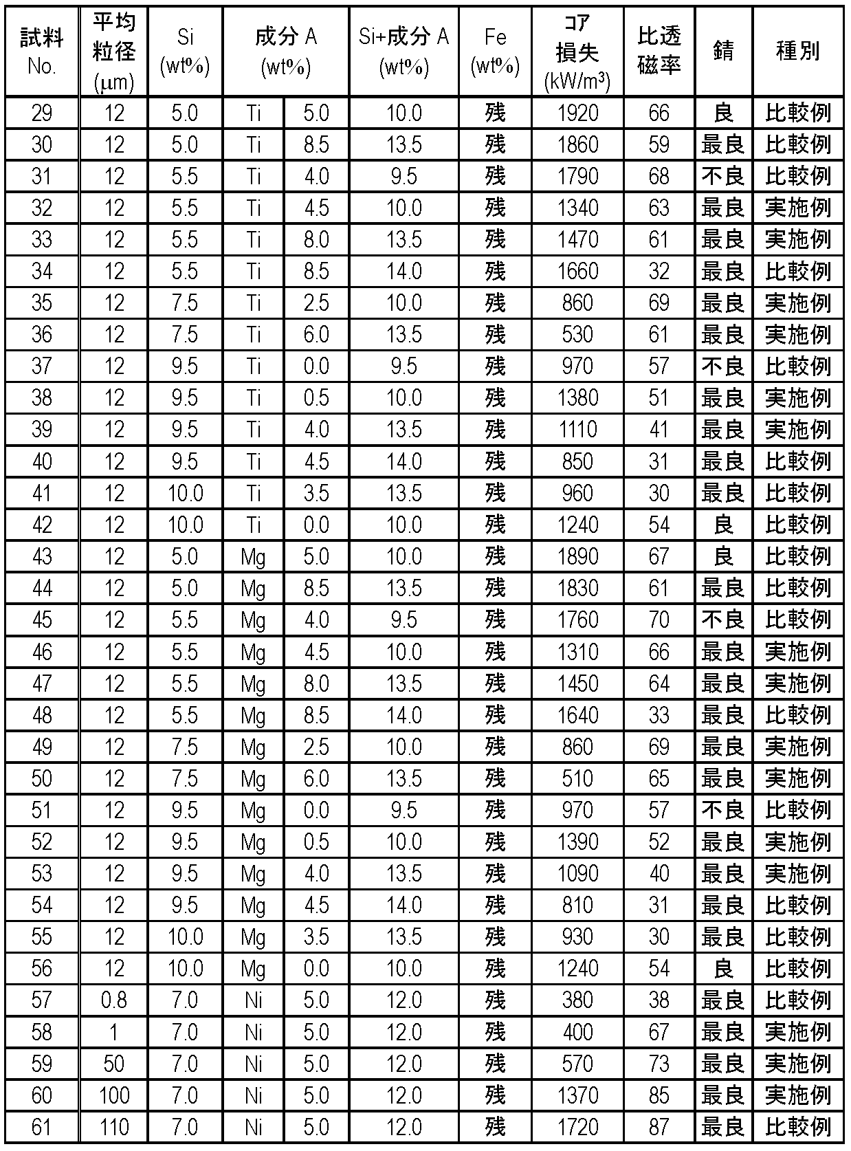
- Various metal magnetic powders described in 1-61 are prepared. To 100 parts by weight of the prepared metal magnetic powder, 0.5 part by weight of silicone resin as an insulating binder and 1.0 part by weight of butyral resin as a binding aid are added, and then a small amount of toluene is added and mixed and kneaded. . Thereafter, the mixture is sized through a sieve to form a mixed powder. The obtained mixed powder is filled in a predetermined mold and pressure-molded at 12 ton / cm 2 to form a molded body. The obtained molded body is heat-treated at 340 ° C. for 60 minutes in an air atmosphere to form an oxide film on the surface of the molded body.
- a toroidal core-shaped molded body having an outer diameter of 14 mm, an inner diameter of 10 mm, and a height of about 2 mm and an E-shaped core-shaped molded body having a side of about 15 mm and a height of about 5 mm are prepared for each sample.
- the toroidal core shaped compact is used for measuring magnetic properties, and the E shaped core compact is used for a corrosion resistance test.
- a magnetic characteristic and corrosion resistance are measured, respectively.
- relative permeability and core loss are measured.
- the relative magnetic permeability is measured at a measurement frequency of 10 kHz using an LCR meter.
- the core loss is measured using an AC BH curve measuring machine at a measurement frequency of 120 kHz and a measurement magnetic flux density of 0.1 T.
- relative permeability 40 or more and core loss 1500 kW / m ⁇ 3 > or less are preferable.
- the corrosion resistance is measured by a corrosion resistance test with a test time of 1000 hours under a high temperature and high humidity condition of a temperature of 85 ° C. and a humidity of 85%. The results are evaluated by examining the appearance of the molded body after the test with an optical microscope and visual observation. “Best” means that the rust cannot be confirmed visually with an optical microscope, “good” means that the rust can be confirmed with the optical microscope but cannot be confirmed with the naked eye, and “bad” means that the rust can be confirmed with both the optical microscope and the naked eye. To do. In the corrosion resistance test in the state of being mounted on a circuit board, rust cannot be confirmed with the naked eye, that is, “best” and “good” samples have no rust dropping on the board, and there is no practical problem.
- the metal magnetic powder is composed of Si, Fe, and component A, and the composition is 5% by weight, and 5.5% ⁇ Si ⁇ 9.5% and 10%.
- ⁇ Si + component A ⁇ 13.5%
- the balance is made of Fe
- the component A shows excellent magnetic properties and corrosion resistance in a composite magnetic material made of one of Ni, Al, Ti, and Mg. .
- the composition of the metal magnetic powder is 5% by weight, 5.5% ⁇ Si ⁇ 7.5%, 10% ⁇ Si + component A ⁇ 13.5%, and the balance is Fe, and component A is:
- component A is:
- a composite magnetic body made of at least one of Ni, Al, Ti, and Mg the magnetic properties and corrosion resistance with higher magnetic permeability are shown.
- the component A is composed of two or more of Ni, Al, Ti, and Mg, the same as long as the total metal magnetic powder is within the composition range of 10% ⁇ Si + component A ⁇ 13.5%. Needless to say, an effect can be obtained. Needless to say, the metal magnetic powder contains a small amount of impurities or additives, but the same effect can be obtained within a few percent.
- a plurality of samples having different saturation magnetic flux densities are produced by changing the pressure at the time of forming the molded body.
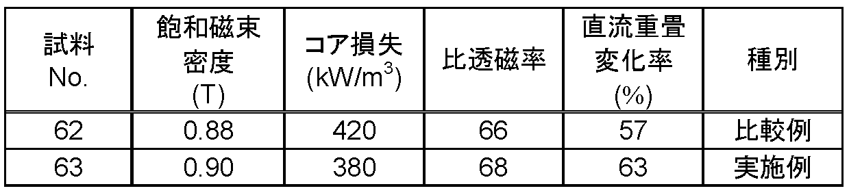
- a metal magnetic powder comprising an average particle diameter of 18 ⁇ m, a composition of 5.0% Ni, 7.5% Si and the remaining Fe by weight is prepared. Then, after adding 1.5 parts by weight of a silicone resin as an insulating binder to 100 parts by weight of the metal magnetic powder, a small amount of toluene is added and mixed and kneaded. Thereafter, the mixture is sized through a sieve to produce a mixed powder. The obtained mixed powder was filled in a predetermined mold, and sample No. 62 and no. Each of 63 is pressure-molded at a pressure of 5 to 15 ton / cm 2 to produce a molded body. The obtained molded body is oxidized at 280 ° C.
- the molded body is formed in a toroidal core shape having an outer diameter of 14 mm, an inner diameter of 10 mm, and a height of about 2 mm.
- the relative permeability, core loss, DC superposition characteristics, and saturation magnetic flux density are measured.
- the relative magnetic permeability is measured at a measurement frequency of 10 kHz using an LCR meter.
- the core loss is measured using an AC BH curve measuring machine at a measurement frequency of 120 kHz and a measurement magnetic flux density of 0.1 T.
- the DC superposition characteristics are evaluated by determining the change rate of the relative permeability when the DC magnetic field is 2400 A / m and the measurement frequency is 10 kHz with an LCR meter.
- the saturation magnetic flux density is determined using a VSM (sample vibration magnetometer) when the magnetic field is 1.2 MA / m.
- the relative permeability is 40 or more
- the core loss is 1500 kW / m 3 or less
- the rate of change of the DC superposition characteristics is 60% or more. Preferably there is.
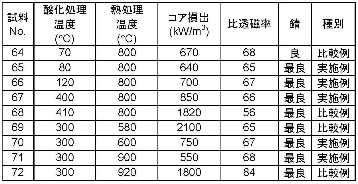
- a plurality of samples are manufactured by changing the heat treatment temperature in the heat treatment in the oxidizing atmosphere and the heat treatment temperature in the non-oxidizing atmosphere.
- a metal magnetic powder having an average particle diameter of 25 ⁇ m and a composition of 4.5% Al, 6.5% Si and the remaining Fe by weight% is prepared.
- To 100 parts by weight of the prepared metal magnetic powder 0.9 parts by weight of silicone resin as an insulating binder and 1.0 part by weight of acrylic resin as a binding aid are added, and a small amount of toluene is added and mixed and kneaded. To do. Thereafter, the particles are sized to produce a mixed powder.
- the obtained mixed powder is filled in a predetermined mold and pressed at a pressure of 10 ton / cm 2 to produce a molded body.
- a step of oxidizing the molded body in an oxidizing atmosphere and a heat treatment step in a non-oxidizing atmosphere are performed.
- the oxidation treatment time is 90 minutes and the heat treatment time is 30 minutes.
- a toroidal core-shaped molded body having an outer diameter of 14 mm, an inner diameter of 10 mm, and a height of about 2 mm is formed for measuring magnetic properties
- an E-shaped core-shaped molded body having a side of about 15 mm and a height of about 5 mm is formed for corrosion resistance testing.
- Samples 65-67 and 70-71 show excellent magnetic properties and corrosion resistance. This is because the treatment in the above temperature range can remove the distortion of the formed body during the molding in the heat treatment step, and in the oxidation treatment step, a stable oxide film is formed on the surface of the metal magnetic powder. This is because it can be formed.
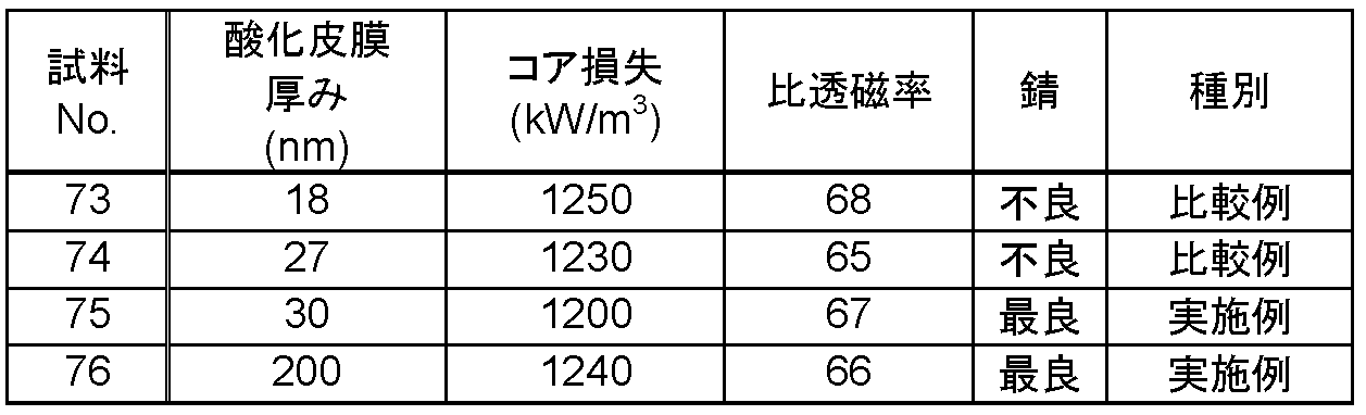
- a plurality of samples are produced by changing the treatment time in the oxidation treatment.
- a metal magnetic powder having an average particle size of 23 ⁇ m and a composition of 5.0% by weight, 5.0% Al, 6.5% Si, and the remaining Fe is prepared.
- a silicone resin as an insulating binder is added to 100 parts by weight of the prepared metal magnetic powder.
- a small amount of toluene is added and dispersed to prepare a mixed powder.
- the obtained mixed powder is filled in a predetermined mold and pressed at a pressure of 13 ton / cm 2 to produce a molded body. Thereafter, the molded body is subjected to an oxidation treatment by changing the treatment time under the condition of 380 ° C. in an air atmosphere. Further, heat treatment is performed at 840 ° C. for 30 minutes in a nitrogen atmosphere.
- a toroidal core shape having an outer diameter of 14 mm, an inner diameter of 10 mm, and a height of about 2 mm is prepared for measuring magnetic characteristics, and an E-shaped shape having a side of about 15 mm and a height of about 5 mm is used for the corrosion resistance test.
- Make a core shape For each sample, a toroidal core shape having an outer diameter of 14 mm, an inner diameter of 10 mm, and a height of about 2 mm is prepared for measuring magnetic characteristics, and an E-shaped shape having a side of about 15 mm and a height of about 5 mm is used for the corrosion resistance test. Make a core shape.
- the thickness of the oxide film is evaluated by measuring the thickness of the metal oxide film exposed on the outermost surface of the core in contact with the mold surface of the E-shaped core of the final product, using Auger electron spectroscopy (AES). .
- AES Auger electron spectroscopy
- Other magnetic property measurements and corrosion resistance tests are performed under the same measurement conditions as in Example 1. The measurement results are shown in (Table 4).
- the thickness of the metal oxide film is 30 nm or more as in Sample 75-76, a stable oxide film is formed on the surface of the metal magnetic powder, so that the composite magnetic material has excellent magnetic properties. It can be seen that it shows corrosion resistance.
- the composite magnetic material produced by the production method according to the present invention has excellent magnetic properties and corrosion resistance, and is particularly useful as a magnetic material used for transformer cores, choke coils and the like.
Landscapes
- Chemical & Material Sciences (AREA)
- Engineering & Computer Science (AREA)
- Mechanical Engineering (AREA)
- Materials Engineering (AREA)
- Metallurgy (AREA)
- Organic Chemistry (AREA)
- Power Engineering (AREA)
- Manufacturing & Machinery (AREA)
- Spectroscopy & Molecular Physics (AREA)
- Dispersion Chemistry (AREA)
- Physics & Mathematics (AREA)
- Soft Magnetic Materials (AREA)
- Powder Metallurgy (AREA)
Abstract
Description

Claims (6)
- 金属磁性粉末と絶縁性結着材とを混合して混合粉を作製するステップと、
前記混合粉を加圧成形して成形体を作製するステップと、
前記成形体を80℃以上400℃以下の酸化雰囲気下で熱処理して前記成形体の表面に酸化皮膜を形成するステップとによって製造される複合磁性体であって、
前記金属磁性粉末がSi、Fe、成分Aからなり、組成が重量%で、5.5%≦Si≦9.5%、10%≦Si+成分A≦13.5%、残部がFeであり、成分Aは、Ni、Al、Ti、Mgの内の少なくとも一つからなる複合磁性体。 - 金属磁性粉末と絶縁性結着材とを混合して混合粉を作製するステップと、
前記混合粉を加圧成形して成形体を作製するステップと、
前記成形体を80℃以上400℃以下の酸化雰囲気下で熱処理して前記成形体の表面に酸化皮膜を形成するステップと、を含み、
前記金属磁性粉末がSi、Fe、成分Aからなり、組成が重量%で、5.5%≦Si≦9.5%、10%≦Si+成分A≦13.5%、残部がFeであり、成分Aは、Ni、Al、Ti、Mgの内の少なくとも一つからなる複合磁性体の製造方法。 - 前記複合磁性体の飽和磁束密度が、0.9T以上であることを特徴とする請求項2記載の複合磁性体の製造方法。
- 前記酸化皮膜の厚みが、30nm以上200nm以下であることを特徴とする請求項2記載の複合磁性体の製造方法。
- 前記金属磁性粉末の平均粒径が1μm以上100μm以下であることを特徴とする請求項2記載の複合磁性体の製造方法。
- 前記成分AはAlである
請求項2に記載の複合磁性体の製造方法。
Priority Applications (4)
| Application Number | Priority Date | Filing Date | Title |
|---|---|---|---|
| EP11800413.4A EP2589450B1 (en) | 2010-06-30 | 2011-06-28 | Composite magnetic material and process for production thereof |
| US13/700,675 US8999075B2 (en) | 2010-06-30 | 2011-06-28 | Composite magnetic material and process for production |
| JP2012522457A JP5903665B2 (ja) | 2010-06-30 | 2011-06-28 | 複合磁性体の製造方法 |
| CN201180031448.4A CN102971100B (zh) | 2010-06-30 | 2011-06-28 | 复合磁性体及其制造方法 |
Applications Claiming Priority (2)
| Application Number | Priority Date | Filing Date | Title |
|---|---|---|---|
| JP2010148739 | 2010-06-30 | ||
| JP2010-148739 | 2010-06-30 |
Publications (1)
| Publication Number | Publication Date |
|---|---|
| WO2012001943A1 true WO2012001943A1 (ja) | 2012-01-05 |
Family
ID=45401685
Family Applications (1)
| Application Number | Title | Priority Date | Filing Date |
|---|---|---|---|
| PCT/JP2011/003666 Ceased WO2012001943A1 (ja) | 2010-06-30 | 2011-06-28 | 複合磁性体とその製造方法 |
Country Status (5)
| Country | Link |
|---|---|
| US (1) | US8999075B2 (ja) |
| EP (1) | EP2589450B1 (ja) |
| JP (1) | JP5903665B2 (ja) |
| CN (1) | CN102971100B (ja) |
| WO (1) | WO2012001943A1 (ja) |
Cited By (9)
| Publication number | Priority date | Publication date | Assignee | Title |
|---|---|---|---|---|
| WO2013108643A1 (ja) * | 2012-01-17 | 2013-07-25 | 株式会社日立産機システム | 圧粉軟磁性体 |
| JP2015026749A (ja) * | 2013-07-27 | 2015-02-05 | 株式会社豊田中央研究所 | 軟磁性粉末、圧粉磁心および軟磁性合金 |
| JPWO2014013896A1 (ja) * | 2012-07-20 | 2016-06-30 | 株式会社村田製作所 | 積層コイル部品の製造方法 |
| WO2017082027A1 (ja) * | 2015-11-10 | 2017-05-18 | 住友電気工業株式会社 | 圧粉成形体、電磁部品、及び圧粉成形体の製造方法 |
| JP2018012883A (ja) * | 2016-07-11 | 2018-01-25 | 大同特殊鋼株式会社 | 軟磁性合金 |
| JP2021002684A (ja) * | 2015-11-10 | 2021-01-07 | 住友電気工業株式会社 | 圧粉成形体の製造方法 |
| JP2021165416A (ja) * | 2020-04-07 | 2021-10-14 | 大同特殊鋼株式会社 | 軟磁性合金粉末、その製造方法、及び圧粉磁心 |
| JP2021185622A (ja) * | 2020-10-05 | 2021-12-09 | 住友電気工業株式会社 | 圧粉成形体、及び電磁部品 |
| US11482355B2 (en) | 2016-07-11 | 2022-10-25 | Daido Steel Co., Ltd. | Soft magnetic alloy |
Families Citing this family (3)
| Publication number | Priority date | Publication date | Assignee | Title |
|---|---|---|---|---|
| WO2016039267A1 (ja) | 2014-09-08 | 2016-03-17 | トヨタ自動車株式会社 | 圧粉磁心、磁心用粉末およびそれらの製造方法 |
| JP6378156B2 (ja) * | 2015-10-14 | 2018-08-22 | トヨタ自動車株式会社 | 圧粉磁心、圧粉磁心用粉末、および圧粉磁心の製造方法 |
| CN111745152B (zh) * | 2019-03-28 | 2024-03-12 | 新东工业株式会社 | 软磁性合金粉末、电子部件以及其制造方法 |
Citations (6)
| Publication number | Priority date | Publication date | Assignee | Title |
|---|---|---|---|---|
| JPH06342714A (ja) | 1993-05-31 | 1994-12-13 | Tokin Corp | 圧粉磁芯およびその製造方法 |
| JPH10144512A (ja) * | 1996-11-13 | 1998-05-29 | Tokin Corp | 圧粉磁心の製造方法 |
| JPH1197228A (ja) * | 1997-09-19 | 1999-04-09 | Tokin Corp | 圧粉磁芯及びその製造方法 |
| JP2000331814A (ja) * | 1999-05-18 | 2000-11-30 | Tokin Corp | 圧粉磁芯及び該圧粉磁芯を用いたチョークコイル |
| JP2001011563A (ja) * | 1999-06-29 | 2001-01-16 | Matsushita Electric Ind Co Ltd | 複合磁性材料の製造方法 |
| JP2003160847A (ja) | 2001-11-26 | 2003-06-06 | Matsushita Electric Ind Co Ltd | 複合磁性材料およびそれを用いた磁性素子とその製造方法 |
Family Cites Families (15)
| Publication number | Priority date | Publication date | Assignee | Title |
|---|---|---|---|---|
| DE69031250T2 (de) * | 1989-06-09 | 1997-12-04 | Matsushita Electric Ind Co Ltd | Magnetisches Material |
| DE69028360T2 (de) * | 1989-06-09 | 1997-01-23 | Matsushita Electric Ind Co Ltd | Verbundmaterial sowie Verfahren zu seiner Herstellung |
| JPH07211531A (ja) * | 1994-01-20 | 1995-08-11 | Tokin Corp | 圧粉磁芯の製造方法 |
| JP3722391B2 (ja) | 1996-09-05 | 2005-11-30 | Necトーキン株式会社 | 複合磁性体およびそれを用いた電磁干渉抑制体 |
| JP4115612B2 (ja) * | 1997-12-25 | 2008-07-09 | 松下電器産業株式会社 | 複合磁性体とその製造方法 |
| SG78328A1 (en) | 1997-12-25 | 2001-02-20 | Matsushita Electric Industrial Co Ltd | Magnetic composite article and manufacturing method of the same and soft magnetic powder of fe-al-si system alloy used in the composite article |
| JP2000049008A (ja) * | 1998-07-29 | 2000-02-18 | Tdk Corp | 圧粉コア用強磁性粉末、圧粉コアおよびその製造方法 |
| US6558565B1 (en) * | 1999-02-10 | 2003-05-06 | Matsushita Electric Industrial Co., Ltd. | Composite magnetic material |
| JP4684461B2 (ja) | 2000-04-28 | 2011-05-18 | パナソニック株式会社 | 磁性素子の製造方法 |
| JP2003332114A (ja) * | 2002-05-09 | 2003-11-21 | Mitsubishi Materials Corp | 室温および高温における機械的強度並びに耐キャビテーション損傷性が共に優れたボンド軟磁性体およびその製造方法 |
| JP2004214418A (ja) * | 2002-12-27 | 2004-07-29 | Neomax Co Ltd | 圧粉磁芯とその合金粉末並びに製造方法 |
| US20080003126A1 (en) * | 2004-09-06 | 2008-01-03 | Mitsubishi Materials Pmg Corporation | Method for Producing Soft Magnetic Metal Powder Coated With Mg-Containing Oxide Film and Method for Producing Composite Soft Magnetic Material Using Said Powder |
| JP2007299871A (ja) * | 2006-04-28 | 2007-11-15 | Matsushita Electric Ind Co Ltd | 複合磁性体の製造方法およびそれを用いて得られた複合磁性体 |
| JP2009117651A (ja) * | 2007-11-07 | 2009-05-28 | Mitsubishi Materials Pmg Corp | 高強度軟磁性複合圧密焼成材およびその製造方法 |
| CN102473501A (zh) * | 2009-08-04 | 2012-05-23 | 松下电器产业株式会社 | 复合磁性体及其制造方法 |
-
2011
- 2011-06-28 EP EP11800413.4A patent/EP2589450B1/en active Active
- 2011-06-28 WO PCT/JP2011/003666 patent/WO2012001943A1/ja not_active Ceased
- 2011-06-28 CN CN201180031448.4A patent/CN102971100B/zh active Active
- 2011-06-28 US US13/700,675 patent/US8999075B2/en active Active
- 2011-06-28 JP JP2012522457A patent/JP5903665B2/ja active Active
Patent Citations (6)
| Publication number | Priority date | Publication date | Assignee | Title |
|---|---|---|---|---|
| JPH06342714A (ja) | 1993-05-31 | 1994-12-13 | Tokin Corp | 圧粉磁芯およびその製造方法 |
| JPH10144512A (ja) * | 1996-11-13 | 1998-05-29 | Tokin Corp | 圧粉磁心の製造方法 |
| JPH1197228A (ja) * | 1997-09-19 | 1999-04-09 | Tokin Corp | 圧粉磁芯及びその製造方法 |
| JP2000331814A (ja) * | 1999-05-18 | 2000-11-30 | Tokin Corp | 圧粉磁芯及び該圧粉磁芯を用いたチョークコイル |
| JP2001011563A (ja) * | 1999-06-29 | 2001-01-16 | Matsushita Electric Ind Co Ltd | 複合磁性材料の製造方法 |
| JP2003160847A (ja) | 2001-11-26 | 2003-06-06 | Matsushita Electric Ind Co Ltd | 複合磁性材料およびそれを用いた磁性素子とその製造方法 |
Cited By (12)
| Publication number | Priority date | Publication date | Assignee | Title |
|---|---|---|---|---|
| WO2013108643A1 (ja) * | 2012-01-17 | 2013-07-25 | 株式会社日立産機システム | 圧粉軟磁性体 |
| JPWO2014013896A1 (ja) * | 2012-07-20 | 2016-06-30 | 株式会社村田製作所 | 積層コイル部品の製造方法 |
| JP2015026749A (ja) * | 2013-07-27 | 2015-02-05 | 株式会社豊田中央研究所 | 軟磁性粉末、圧粉磁心および軟磁性合金 |
| WO2017082027A1 (ja) * | 2015-11-10 | 2017-05-18 | 住友電気工業株式会社 | 圧粉成形体、電磁部品、及び圧粉成形体の製造方法 |
| JP2017092225A (ja) * | 2015-11-10 | 2017-05-25 | 住友電気工業株式会社 | 圧粉成形体、電磁部品、及び圧粉成形体の製造方法 |
| JP2021002684A (ja) * | 2015-11-10 | 2021-01-07 | 住友電気工業株式会社 | 圧粉成形体の製造方法 |
| JP2018012883A (ja) * | 2016-07-11 | 2018-01-25 | 大同特殊鋼株式会社 | 軟磁性合金 |
| US11482355B2 (en) | 2016-07-11 | 2022-10-25 | Daido Steel Co., Ltd. | Soft magnetic alloy |
| JP2021165416A (ja) * | 2020-04-07 | 2021-10-14 | 大同特殊鋼株式会社 | 軟磁性合金粉末、その製造方法、及び圧粉磁心 |
| JP7505237B2 (ja) | 2020-04-07 | 2024-06-25 | 大同特殊鋼株式会社 | 軟磁性合金粉末、その製造方法、及び圧粉磁心 |
| JP2021185622A (ja) * | 2020-10-05 | 2021-12-09 | 住友電気工業株式会社 | 圧粉成形体、及び電磁部品 |
| JP7386832B2 (ja) | 2020-10-05 | 2023-11-27 | 住友電気工業株式会社 | 圧粉成形体、及び電磁部品 |
Also Published As
| Publication number | Publication date |
|---|---|
| EP2589450A1 (en) | 2013-05-08 |
| US20130136933A1 (en) | 2013-05-30 |
| JP5903665B2 (ja) | 2016-04-13 |
| EP2589450A4 (en) | 2017-12-06 |
| EP2589450B1 (en) | 2019-08-28 |
| CN102971100B (zh) | 2016-03-09 |
| US8999075B2 (en) | 2015-04-07 |
| CN102971100A (zh) | 2013-03-13 |
| JPWO2012001943A1 (ja) | 2013-08-22 |
Similar Documents
| Publication | Publication Date | Title |
|---|---|---|
| JP5903665B2 (ja) | 複合磁性体の製造方法 | |
| JP4613622B2 (ja) | 軟磁性材料および圧粉磁心 | |
| US8328955B2 (en) | Process for producing composite magnetic material, dust core formed from same, and process for producing dust core | |
| CN105917422B (zh) | 磁芯以及使用磁芯的线圈部件 | |
| JP5022999B2 (ja) | 圧粉磁心及びその製造方法 | |
| JP5368686B2 (ja) | 軟磁性材料、圧粉磁心、軟磁性材料の製造方法、および圧粉磁心の製造方法 | |
| JP6358491B2 (ja) | 圧粉磁心、それを用いたコイル部品および圧粉磁心の製造方法 | |
| JP6365670B2 (ja) | 磁心、磁心の製造方法およびコイル部品 | |
| JP5926011B2 (ja) | 磁性材料およびそれを用いたコイル部品 | |
| WO2013073180A1 (ja) | 複合磁性材料とそれを用いたコイル埋設型磁性素子およびその製造方法 | |
| WO2013005454A1 (ja) | 磁性材料およびそれを用いたコイル部品 | |
| EP2434502A1 (en) | Composite magnetic body and method for producing the same | |
| CN106537527A (zh) | 磁芯的制造方法、磁芯以及使用该磁芯的线圈部件 | |
| JP2009185312A (ja) | 複合軟磁性材料、それを用いた圧粉磁心、およびそれらの製造方法 | |
| CN100439012C (zh) | 铁基软磁粉末 | |
| EP1077454A1 (en) | Composite magnetic material | |
| JP5023041B2 (ja) | 圧粉磁心及びその製造方法 | |
| JP2019201155A (ja) | 圧粉磁芯およびインダクタ素子 | |
| CN108698124A (zh) | 新组合物和方法 | |
| CN102171776B (zh) | 复合磁性材料及其制造方法 | |
| JP5439888B2 (ja) | 複合磁性材料およびその製造方法 | |
| JP7045905B2 (ja) | 軟磁性粉末及びその製造方法 | |
| JP6460505B2 (ja) | 圧粉磁心の製造方法 | |
| JP6229166B2 (ja) | インダクタ用複合磁性材料とその製造方法 | |
| CN109716454B (zh) | 磁芯及线圈部件 |
Legal Events
| Date | Code | Title | Description |
|---|---|---|---|
| WWE | Wipo information: entry into national phase |
Ref document number: 201180031448.4 Country of ref document: CN |
|
| 121 | Ep: the epo has been informed by wipo that ep was designated in this application |
Ref document number: 11800413 Country of ref document: EP Kind code of ref document: A1 |
|
| WWE | Wipo information: entry into national phase |
Ref document number: 2012522457 Country of ref document: JP |
|
| WWE | Wipo information: entry into national phase |
Ref document number: 13700675 Country of ref document: US |
|
| WWE | Wipo information: entry into national phase |
Ref document number: 2011800413 Country of ref document: EP |
|
| NENP | Non-entry into the national phase |
Ref country code: DE |