WO2012002534A1 - 惰行制御装置 - Google Patents
惰行制御装置 Download PDFInfo
- Publication number
- WO2012002534A1 WO2012002534A1 PCT/JP2011/065182 JP2011065182W WO2012002534A1 WO 2012002534 A1 WO2012002534 A1 WO 2012002534A1 JP 2011065182 W JP2011065182 W JP 2011065182W WO 2012002534 A1 WO2012002534 A1 WO 2012002534A1
- Authority
- WO
- WIPO (PCT)
- Prior art keywords
- clutch
- coasting control
- amount
- cylinder chamber
- oil
- Prior art date
- Legal status (The legal status is an assumption and is not a legal conclusion. Google has not performed a legal analysis and makes no representation as to the accuracy of the status listed.)
- Ceased
Links
Images


Classifications
-
- F—MECHANICAL ENGINEERING; LIGHTING; HEATING; WEAPONS; BLASTING
- F16—ENGINEERING ELEMENTS AND UNITS; GENERAL MEASURES FOR PRODUCING AND MAINTAINING EFFECTIVE FUNCTIONING OF MACHINES OR INSTALLATIONS; THERMAL INSULATION IN GENERAL
- F16D—COUPLINGS FOR TRANSMITTING ROTATION; CLUTCHES; BRAKES
- F16D48/00—External control of clutches
- F16D48/06—Control by electric or electronic means, e.g. of fluid pressure
-
- F—MECHANICAL ENGINEERING; LIGHTING; HEATING; WEAPONS; BLASTING
- F02—COMBUSTION ENGINES; HOT-GAS OR COMBUSTION-PRODUCT ENGINE PLANTS
- F02D—CONTROLLING COMBUSTION ENGINES
- F02D11/00—Arrangements for, or adaptations to, non-automatic engine control initiation means, e.g. operator initiated
- F02D11/04—Arrangements for, or adaptations to, non-automatic engine control initiation means, e.g. operator initiated characterised by mechanical control linkages
-
- F—MECHANICAL ENGINEERING; LIGHTING; HEATING; WEAPONS; BLASTING
- F02—COMBUSTION ENGINES; HOT-GAS OR COMBUSTION-PRODUCT ENGINE PLANTS
- F02D—CONTROLLING COMBUSTION ENGINES
- F02D29/00—Controlling engines, such controlling being peculiar to the devices driven thereby, the devices being other than parts or accessories essential to engine operation, e.g. controlling of engines by signals external thereto
- F02D29/02—Controlling engines, such controlling being peculiar to the devices driven thereby, the devices being other than parts or accessories essential to engine operation, e.g. controlling of engines by signals external thereto peculiar to engines driving vehicles; peculiar to engines driving variable pitch propellers
-
- F—MECHANICAL ENGINEERING; LIGHTING; HEATING; WEAPONS; BLASTING
- F02—COMBUSTION ENGINES; HOT-GAS OR COMBUSTION-PRODUCT ENGINE PLANTS
- F02D—CONTROLLING COMBUSTION ENGINES
- F02D41/00—Electrical control of supply of combustible mixture or its constituents
- F02D41/02—Circuit arrangements for generating control signals
- F02D41/04—Introducing corrections for particular operating conditions
- F02D41/12—Introducing corrections for particular operating conditions for deceleration
-
- F—MECHANICAL ENGINEERING; LIGHTING; HEATING; WEAPONS; BLASTING
- F16—ENGINEERING ELEMENTS AND UNITS; GENERAL MEASURES FOR PRODUCING AND MAINTAINING EFFECTIVE FUNCTIONING OF MACHINES OR INSTALLATIONS; THERMAL INSULATION IN GENERAL
- F16D—COUPLINGS FOR TRANSMITTING ROTATION; CLUTCHES; BRAKES
- F16D48/00—External control of clutches
- F16D48/06—Control by electric or electronic means, e.g. of fluid pressure
- F16D48/066—Control of fluid pressure, e.g. using an accumulator
-
- F—MECHANICAL ENGINEERING; LIGHTING; HEATING; WEAPONS; BLASTING
- F16—ENGINEERING ELEMENTS AND UNITS; GENERAL MEASURES FOR PRODUCING AND MAINTAINING EFFECTIVE FUNCTIONING OF MACHINES OR INSTALLATIONS; THERMAL INSULATION IN GENERAL
- F16D—COUPLINGS FOR TRANSMITTING ROTATION; CLUTCHES; BRAKES
- F16D48/00—External control of clutches
- F16D48/02—Control by fluid pressure
- F16D2048/0227—Source of pressure producing the clutch engagement or disengagement action within a circuit; Means for initiating command action in power assisted devices
- F16D2048/0254—Double actuation, i.e. two actuation means can produce independently an engagement or disengagement of the clutch
-
- F—MECHANICAL ENGINEERING; LIGHTING; HEATING; WEAPONS; BLASTING
- F16—ENGINEERING ELEMENTS AND UNITS; GENERAL MEASURES FOR PRODUCING AND MAINTAINING EFFECTIVE FUNCTIONING OF MACHINES OR INSTALLATIONS; THERMAL INSULATION IN GENERAL
- F16D—COUPLINGS FOR TRANSMITTING ROTATION; CLUTCHES; BRAKES
- F16D2500/00—External control of clutches by electric or electronic means
- F16D2500/10—System to be controlled
- F16D2500/102—Actuator
- F16D2500/1021—Electrical type
- F16D2500/1023—Electric motor
- F16D2500/1024—Electric motor combined with hydraulic actuation
-
- F—MECHANICAL ENGINEERING; LIGHTING; HEATING; WEAPONS; BLASTING
- F16—ENGINEERING ELEMENTS AND UNITS; GENERAL MEASURES FOR PRODUCING AND MAINTAINING EFFECTIVE FUNCTIONING OF MACHINES OR INSTALLATIONS; THERMAL INSULATION IN GENERAL
- F16D—COUPLINGS FOR TRANSMITTING ROTATION; CLUTCHES; BRAKES
- F16D2500/00—External control of clutches by electric or electronic means
- F16D2500/10—System to be controlled
- F16D2500/104—Clutch
- F16D2500/10406—Clutch position
- F16D2500/10412—Transmission line of a vehicle
-
- F—MECHANICAL ENGINEERING; LIGHTING; HEATING; WEAPONS; BLASTING
- F16—ENGINEERING ELEMENTS AND UNITS; GENERAL MEASURES FOR PRODUCING AND MAINTAINING EFFECTIVE FUNCTIONING OF MACHINES OR INSTALLATIONS; THERMAL INSULATION IN GENERAL
- F16D—COUPLINGS FOR TRANSMITTING ROTATION; CLUTCHES; BRAKES
- F16D2500/00—External control of clutches by electric or electronic means
- F16D2500/30—Signal inputs
- F16D2500/304—Signal inputs from the clutch
- F16D2500/30401—On-off signal indicating the engage or disengaged position of the clutch
-
- F—MECHANICAL ENGINEERING; LIGHTING; HEATING; WEAPONS; BLASTING
- F16—ENGINEERING ELEMENTS AND UNITS; GENERAL MEASURES FOR PRODUCING AND MAINTAINING EFFECTIVE FUNCTIONING OF MACHINES OR INSTALLATIONS; THERMAL INSULATION IN GENERAL
- F16D—COUPLINGS FOR TRANSMITTING ROTATION; CLUTCHES; BRAKES
- F16D2500/00—External control of clutches by electric or electronic means
- F16D2500/30—Signal inputs
- F16D2500/305—Signal inputs from the clutch cooling
- F16D2500/3055—Cooling oil properties
- F16D2500/3058—Cooling oil pressure
-
- F—MECHANICAL ENGINEERING; LIGHTING; HEATING; WEAPONS; BLASTING
- F16—ENGINEERING ELEMENTS AND UNITS; GENERAL MEASURES FOR PRODUCING AND MAINTAINING EFFECTIVE FUNCTIONING OF MACHINES OR INSTALLATIONS; THERMAL INSULATION IN GENERAL
- F16D—COUPLINGS FOR TRANSMITTING ROTATION; CLUTCHES; BRAKES
- F16D2500/00—External control of clutches by electric or electronic means
- F16D2500/30—Signal inputs
- F16D2500/306—Signal inputs from the engine
- F16D2500/3067—Speed of the engine
-
- F—MECHANICAL ENGINEERING; LIGHTING; HEATING; WEAPONS; BLASTING
- F16—ENGINEERING ELEMENTS AND UNITS; GENERAL MEASURES FOR PRODUCING AND MAINTAINING EFFECTIVE FUNCTIONING OF MACHINES OR INSTALLATIONS; THERMAL INSULATION IN GENERAL
- F16D—COUPLINGS FOR TRANSMITTING ROTATION; CLUTCHES; BRAKES
- F16D2500/00—External control of clutches by electric or electronic means
- F16D2500/30—Signal inputs
- F16D2500/308—Signal inputs from the transmission
- F16D2500/30806—Engaged transmission ratio
-
- F—MECHANICAL ENGINEERING; LIGHTING; HEATING; WEAPONS; BLASTING
- F16—ENGINEERING ELEMENTS AND UNITS; GENERAL MEASURES FOR PRODUCING AND MAINTAINING EFFECTIVE FUNCTIONING OF MACHINES OR INSTALLATIONS; THERMAL INSULATION IN GENERAL
- F16D—COUPLINGS FOR TRANSMITTING ROTATION; CLUTCHES; BRAKES
- F16D2500/00—External control of clutches by electric or electronic means
- F16D2500/30—Signal inputs
- F16D2500/31—Signal inputs from the vehicle
- F16D2500/3101—Detection of a brake actuation by a sensor on the brake
-
- F—MECHANICAL ENGINEERING; LIGHTING; HEATING; WEAPONS; BLASTING
- F16—ENGINEERING ELEMENTS AND UNITS; GENERAL MEASURES FOR PRODUCING AND MAINTAINING EFFECTIVE FUNCTIONING OF MACHINES OR INSTALLATIONS; THERMAL INSULATION IN GENERAL
- F16D—COUPLINGS FOR TRANSMITTING ROTATION; CLUTCHES; BRAKES
- F16D2500/00—External control of clutches by electric or electronic means
- F16D2500/30—Signal inputs
- F16D2500/31—Signal inputs from the vehicle
- F16D2500/3108—Vehicle speed
-
- F—MECHANICAL ENGINEERING; LIGHTING; HEATING; WEAPONS; BLASTING
- F16—ENGINEERING ELEMENTS AND UNITS; GENERAL MEASURES FOR PRODUCING AND MAINTAINING EFFECTIVE FUNCTIONING OF MACHINES OR INSTALLATIONS; THERMAL INSULATION IN GENERAL
- F16D—COUPLINGS FOR TRANSMITTING ROTATION; CLUTCHES; BRAKES
- F16D2500/00—External control of clutches by electric or electronic means
- F16D2500/30—Signal inputs
- F16D2500/314—Signal inputs from the user
- F16D2500/31406—Signal inputs from the user input from pedals
- F16D2500/31413—Clutch pedal position
-
- F—MECHANICAL ENGINEERING; LIGHTING; HEATING; WEAPONS; BLASTING
- F16—ENGINEERING ELEMENTS AND UNITS; GENERAL MEASURES FOR PRODUCING AND MAINTAINING EFFECTIVE FUNCTIONING OF MACHINES OR INSTALLATIONS; THERMAL INSULATION IN GENERAL
- F16D—COUPLINGS FOR TRANSMITTING ROTATION; CLUTCHES; BRAKES
- F16D2500/00—External control of clutches by electric or electronic means
- F16D2500/30—Signal inputs
- F16D2500/314—Signal inputs from the user
- F16D2500/3146—Signal inputs from the user input from levers
- F16D2500/31466—Gear lever
-
- F—MECHANICAL ENGINEERING; LIGHTING; HEATING; WEAPONS; BLASTING
- F16—ENGINEERING ELEMENTS AND UNITS; GENERAL MEASURES FOR PRODUCING AND MAINTAINING EFFECTIVE FUNCTIONING OF MACHINES OR INSTALLATIONS; THERMAL INSULATION IN GENERAL
- F16D—COUPLINGS FOR TRANSMITTING ROTATION; CLUTCHES; BRAKES
- F16D2500/00—External control of clutches by electric or electronic means
- F16D2500/30—Signal inputs
- F16D2500/314—Signal inputs from the user
- F16D2500/3146—Signal inputs from the user input from levers
- F16D2500/31473—Parking brake lever
-
- F—MECHANICAL ENGINEERING; LIGHTING; HEATING; WEAPONS; BLASTING
- F16—ENGINEERING ELEMENTS AND UNITS; GENERAL MEASURES FOR PRODUCING AND MAINTAINING EFFECTIVE FUNCTIONING OF MACHINES OR INSTALLATIONS; THERMAL INSULATION IN GENERAL
- F16D—COUPLINGS FOR TRANSMITTING ROTATION; CLUTCHES; BRAKES
- F16D2500/00—External control of clutches by electric or electronic means
- F16D2500/30—Signal inputs
- F16D2500/314—Signal inputs from the user
- F16D2500/31493—Switches on the dashboard
-
- F—MECHANICAL ENGINEERING; LIGHTING; HEATING; WEAPONS; BLASTING
- F16—ENGINEERING ELEMENTS AND UNITS; GENERAL MEASURES FOR PRODUCING AND MAINTAINING EFFECTIVE FUNCTIONING OF MACHINES OR INSTALLATIONS; THERMAL INSULATION IN GENERAL
- F16D—COUPLINGS FOR TRANSMITTING ROTATION; CLUTCHES; BRAKES
- F16D2500/00—External control of clutches by electric or electronic means
- F16D2500/50—Problem to be solved by the control system
- F16D2500/502—Relating the clutch
- F16D2500/50293—Reduction of vibrations
-
- F—MECHANICAL ENGINEERING; LIGHTING; HEATING; WEAPONS; BLASTING
- F16—ENGINEERING ELEMENTS AND UNITS; GENERAL MEASURES FOR PRODUCING AND MAINTAINING EFFECTIVE FUNCTIONING OF MACHINES OR INSTALLATIONS; THERMAL INSULATION IN GENERAL
- F16D—COUPLINGS FOR TRANSMITTING ROTATION; CLUTCHES; BRAKES
- F16D2500/00—External control of clutches by electric or electronic means
- F16D2500/50—Problem to be solved by the control system
- F16D2500/504—Relating the engine
- F16D2500/5045—Control of engine at idle, i.e. controlling engine idle conditions, e.g. idling speed
-
- F—MECHANICAL ENGINEERING; LIGHTING; HEATING; WEAPONS; BLASTING
- F16—ENGINEERING ELEMENTS AND UNITS; GENERAL MEASURES FOR PRODUCING AND MAINTAINING EFFECTIVE FUNCTIONING OF MACHINES OR INSTALLATIONS; THERMAL INSULATION IN GENERAL
- F16D—COUPLINGS FOR TRANSMITTING ROTATION; CLUTCHES; BRAKES
- F16D2500/00—External control of clutches by electric or electronic means
- F16D2500/50—Problem to be solved by the control system
- F16D2500/508—Relating driving conditions
- F16D2500/50841—Hill hold
-
- F—MECHANICAL ENGINEERING; LIGHTING; HEATING; WEAPONS; BLASTING
- F16—ENGINEERING ELEMENTS AND UNITS; GENERAL MEASURES FOR PRODUCING AND MAINTAINING EFFECTIVE FUNCTIONING OF MACHINES OR INSTALLATIONS; THERMAL INSULATION IN GENERAL
- F16D—COUPLINGS FOR TRANSMITTING ROTATION; CLUTCHES; BRAKES
- F16D2500/00—External control of clutches by electric or electronic means
- F16D2500/50—Problem to be solved by the control system
- F16D2500/508—Relating driving conditions
- F16D2500/5085—Coasting
-
- F—MECHANICAL ENGINEERING; LIGHTING; HEATING; WEAPONS; BLASTING
- F16—ENGINEERING ELEMENTS AND UNITS; GENERAL MEASURES FOR PRODUCING AND MAINTAINING EFFECTIVE FUNCTIONING OF MACHINES OR INSTALLATIONS; THERMAL INSULATION IN GENERAL
- F16D—COUPLINGS FOR TRANSMITTING ROTATION; CLUTCHES; BRAKES
- F16D2500/00—External control of clutches by electric or electronic means
- F16D2500/70—Details about the implementation of the control system
- F16D2500/702—Look-up tables
- F16D2500/70205—Clutch actuator
- F16D2500/70217—Pressure
-
- F—MECHANICAL ENGINEERING; LIGHTING; HEATING; WEAPONS; BLASTING
- F16—ENGINEERING ELEMENTS AND UNITS; GENERAL MEASURES FOR PRODUCING AND MAINTAINING EFFECTIVE FUNCTIONING OF MACHINES OR INSTALLATIONS; THERMAL INSULATION IN GENERAL
- F16D—COUPLINGS FOR TRANSMITTING ROTATION; CLUTCHES; BRAKES
- F16D2500/00—External control of clutches by electric or electronic means
- F16D2500/70—Details about the implementation of the control system
- F16D2500/702—Look-up tables
- F16D2500/70252—Clutch torque
- F16D2500/7027—Engine speed
-
- F—MECHANICAL ENGINEERING; LIGHTING; HEATING; WEAPONS; BLASTING
- F16—ENGINEERING ELEMENTS AND UNITS; GENERAL MEASURES FOR PRODUCING AND MAINTAINING EFFECTIVE FUNCTIONING OF MACHINES OR INSTALLATIONS; THERMAL INSULATION IN GENERAL
- F16D—COUPLINGS FOR TRANSMITTING ROTATION; CLUTCHES; BRAKES
- F16D2500/00—External control of clutches by electric or electronic means
- F16D2500/70—Details about the implementation of the control system
- F16D2500/704—Output parameters from the control unit; Target parameters to be controlled
- F16D2500/70422—Clutch parameters
- F16D2500/70424—Outputting a clutch engaged-disengaged signal
-
- F—MECHANICAL ENGINEERING; LIGHTING; HEATING; WEAPONS; BLASTING
- F16—ENGINEERING ELEMENTS AND UNITS; GENERAL MEASURES FOR PRODUCING AND MAINTAINING EFFECTIVE FUNCTIONING OF MACHINES OR INSTALLATIONS; THERMAL INSULATION IN GENERAL
- F16D—COUPLINGS FOR TRANSMITTING ROTATION; CLUTCHES; BRAKES
- F16D2500/00—External control of clutches by electric or electronic means
- F16D2500/70—Details about the implementation of the control system
- F16D2500/704—Output parameters from the control unit; Target parameters to be controlled
- F16D2500/70446—Clutch cooling parameters
- F16D2500/70448—Clutch cooling parameters for regulating the amount of fluid flow
-
- Y—GENERAL TAGGING OF NEW TECHNOLOGICAL DEVELOPMENTS; GENERAL TAGGING OF CROSS-SECTIONAL TECHNOLOGIES SPANNING OVER SEVERAL SECTIONS OF THE IPC; TECHNICAL SUBJECTS COVERED BY FORMER USPC CROSS-REFERENCE ART COLLECTIONS [XRACs] AND DIGESTS
- Y02—TECHNOLOGIES OR APPLICATIONS FOR MITIGATION OR ADAPTATION AGAINST CLIMATE CHANGE
- Y02T—CLIMATE CHANGE MITIGATION TECHNOLOGIES RELATED TO TRANSPORTATION
- Y02T10/00—Road transport of goods or passengers
- Y02T10/60—Other road transportation technologies with climate change mitigation effect
Definitions
- the present invention relates to a coasting control device mounted on a vehicle equipped with a manual and automatic clutch system, and in particular, to reduce the uncomfortable feeling that a driver feels when the clutch pedal is depressed during coasting control.
- the present invention relates to a coasting control device capable of
- the state in which the engine does not work to the outside is not limited to the above-described idle when the clutch is disengaged, but also occurs while the vehicle is running. At this time, the engine simply rotates at an engine speed corresponding to the accelerator opening degree as in the case of flying, and does not contribute to acceleration / deceleration of the vehicle. Therefore, fuel is consumed only for rotating the engine, which is very wasteful.
- the present applicant has proposed a coasting control device that performs coasting control that reduces fuel consumption by disengaging the clutch and returning the engine to an idle state when the engine is rotating but does not work to the outside ( Patent Document 2).
- the coasting control can be applied to any vehicle that can automatically turn off the engine output (automatically engage / disengage the clutch) as described above. Therefore, the coasting control is not limited to a manual clutch system (manual T / M), but is also automatic. The same effect can be obtained also in other clutch systems (ordinary torque converter AT and AMT).
- the clutch may be disengaged even when the driver depresses the accelerator with the intention of accelerating, and the driver feels torque loss when shifting from deceleration to acceleration, and feels uncomfortable. is there.
- the present applicant creates a coasting control determination map using the accelerator opening and the clutch rotational speed as indices, and on this coasting control determination map, the coasting where the coordinate points of the accelerator opening and the clutch rotational speed are set in advance.
- a coasting control device is being proposed that starts coasting control when the control threshold line passes in the direction in which the accelerator opening decreases.
- the clutch master cylinder 53 mechanically coupled to the clutch pedal 52 supplies operating oil to the clutch-free operating cylinder 54. It has become.
- a clutch-free actuator unit 55 controlled by an electronic control unit (ECU) also supplies operating oil to the clutch-free operating cylinder 54.
- the clutch free operating cylinder 54 supplies operating oil to the clutch slave cylinder 56.
- the piston 56 a of the clutch slave cylinder 56 is mechanically connected to the movable part of the clutch 58.
- a clutch-free operating cylinder 54 As shown in FIG. 12, a clutch-free operating cylinder 54, a solenoid valve 62 constituting a clutch-free actuator unit 55, a relief valve 63, and a hydraulic pump 64 are provided in the clutch-free actuator 65.
- a primary piston 66 and a secondary piston 67 are arranged in series.
- the primary piston 66 When the primary piston 66 is stroked by the operating oil from the clutch master cylinder 53, the secondary piston 67 is caused to stroke. ing. Further, the secondary piston 67 is stroked by the operating oil supplied from the clutch free actuator unit 55 to the intermediate cylinder chamber 61a which is a cylinder chamber between the primary piston 66 and the secondary piston 67.
- the clutch slave cylinder 56 is supplied with operating oil in accordance with the stroke of the secondary piston 67. With such a configuration, when manual operation is performed, the clutch disengagement and engagement according to the manual operation is performed. When the manual operation is not performed, the clutch disengagement / engagement is performed as controlled by the clutch-free actuator unit 55 by the electronic control unit.
- the coasting control device executes coasting control if a predetermined condition is satisfied regardless of the driver's will, the driver is usually not aware that the coasting control is being performed. Therefore, the driver may step on the clutch pedal 52 during coasting control.
- an object of the present invention is to solve the above-mentioned problems, and in a coasting control device mounted on a vehicle having a manual type and automatic type clutch system, a driver when the clutch pedal is depressed during coasting control.
- An object of the present invention is to provide a coasting control device that can reduce a sense of incongruity.
- the present invention was devised to achieve the above object, and is a clutch system in which operating oil is supplied by depressing a clutch pedal or controlling an actuator, and the clutch is connected and disconnected according to the amount of the supplied operating oil.
- the clutch is disengaged by the actuator and coasting control is performed to reduce the engine speed to the idle speed.
- a clutch control unit is provided for controlling so that when the clutch pedal is depressed during coasting control, the supplied operating oil in an amount corresponding to the depression amount of the clutch pedal is discharged from the actuator.
- the coasting control device is provided for controlling so that when the clutch pedal is depressed during coasting control, the supplied operating oil in an amount corresponding to the depression amount of the clutch pedal is discharged from the actuator.
- a clutch pedal depression amount sensor for measuring a depression amount of the clutch pedal, wherein the clutch system includes a clutch-free operating cylinder having a primary piston and a secondary piston arranged in series;
- a hydraulic pump that supplies hydraulic oil to an intermediate cylinder chamber that is a cylinder chamber of the cylinder, and a solenoid valve that controls an amount of hydraulic oil discharged from the intermediate cylinder chamber, and the clutch control unit includes: According to the depression amount of the clutch pedal measured by the clutch pedal depression amount sensor, the amount of the working oil to be discharged from the intermediate cylinder chamber is obtained, and the determined amount of the working oil is discharged from the intermediate cylinder chamber.
- the actuator It may control the solenoid valve.
- the clutch system includes a clutch-free operating cylinder having a primary piston and a secondary piston arranged in series, and a hydraulic pump that supplies operating oil to an intermediate cylinder chamber that is a cylinder chamber between the primary piston and the secondary piston.
- the actuator having a solenoid valve that controls the amount of operating oil discharged from the intermediate cylinder chamber, and a hydraulic sensor that measures the hydraulic pressure of the operating oil in the intermediate cylinder chamber, and the clutch control unit includes: By controlling the solenoid valve of the actuator so that the oil pressure measured by the oil pressure sensor is constant, the amount of operating oil corresponding to the amount of depression of the clutch pedal is discharged from the intermediate cylinder chamber. May be.
- a coasting control device capable of reducing the uncomfortable feeling felt by the driver when the clutch pedal is depressed during coasting control.
- 1 is an input / output configuration diagram of a vehicle to which a coasting control device of the present invention is applied.
- 1 is a block configuration diagram of a vehicle clutch system to which a coasting control device of the present invention is applied.
- it is an operation
- it is a graph image figure of a coasting control determination map.
- it is a graph for demonstrating the fuel consumption reduction effect by coasting control.
- it is a figure of the coasting control determination map in which coasting control was actually performed. It is a flowchart explaining the control flow of the coasting control apparatus of this invention. In this invention, it is a figure explaining the state of the clutch system in coasting control.
- FIG. 2 is a block diagram of a manual and automatic clutch system.
- FIG. 12 is a more detailed block diagram of the clutch system of FIG. 11.
- FIG. 1 is an input / output configuration diagram of a vehicle to which the coasting control device according to the present embodiment is applied.
- the vehicle is provided with an electronic control unit 11 that mainly controls a transmission and a clutch, and an ECM (engine control module) 12 that mainly controls an engine.
- ECM engine control module
- the electronic control unit 11 includes a shift knob switch, a transmission shift sensor, a select sensor, a neutral switch, a T / M rotation sensor, a vehicle speed sensor, an idle switch, a manual changeover switch, a parking brake switch, a door switch, a brake switch, and a half clutch.
- the input signal lines of the adjustment switch, clutch sensor, and hydraulic switch are connected.
- a clutch pedal depression amount sensor 13 for measuring the depression amount of the clutch pedal 52 is provided, and an input signal line of the clutch pedal depression amount sensor 13 is also connected to the electronic control unit 11.
- the electronic control unit 11 is connected to the motor and solenoid valve 62 of the hydraulic pump 64 of the clutch system 51, the slope start assisting valve, and the output signal lines of the warning & meter.
- the ECM 12 is connected to various input signal lines and output signal lines used for engine control (not shown).
- the ECM 12 can transmit each signal of the engine speed, the accelerator opening degree, and the engine rotation change request to the electronic control unit 11 via a CAN (Controller Area Network) transmission path.
- CAN Controller Area Network
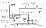
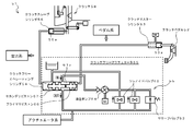
- the vehicle clutch system 51 is supplied with operating oil by depressing the clutch pedal 52 or controlling an actuator (clutch free actuator unit) 55, and the clutch is operated according to the amount of operating oil supplied.
- This is a manual and automatic clutch system that has a clutch-free operating cylinder 54 that connects and disconnects 58, and that can both connect and disconnect the clutch by the clutch pedal 52 and the clutch by the actuator.
- the vehicle clutch system 51 includes a clutch-free operating cylinder 54 having a primary piston 66 and a secondary piston 67 arranged in series, and an intermediate cylinder that is a cylinder chamber between the primary piston 66 and the secondary piston 67.
- a clutch-free actuator unit 55 serving as an actuator for supplying operating oil to the chamber 61a and a piston 53a mechanically connected to the clutch pedal 52 are provided, and the primary piston 66 side of the clutch-free operating cylinder 54 is moved by the stroke of the piston 53a.
- a clutch master cylinder 53 that supplies hydraulic oil to a cylinder chamber (pedal side cylinder chamber) 61b and a movable part of the clutch 58 are mechanically connected to a clutch-free operating cylinder 5
- the operation oil is supplied by the stroke of the secondary piston 67 includes a clutch slave cylinder 56 having a piston 56a which performs connection and disconnection of the clutch 58 according to the amount of operation oil is the supply, a.
- the clutch-free actuator unit 55 includes a hydraulic pump 64 that supplies operating oil to the intermediate cylinder chamber 61a, a solenoid valve 62 that controls the amount of operating oil discharged from the intermediate cylinder chamber 61a, and a relief valve 63.
- a free operating cylinder 54 and a clutch free actuator 65 are disposed.
- FIG. 2 shows that the clutch pedal 52 is not depressed and the clutch 58 is in contact.
- the piston 53a of the clutch master cylinder 53 is moved to the left side in the drawing according to the depression amount.
- the operating oil is supplied to the pedal side cylinder chamber 61b of the clutch free operating cylinder 54, and the primary piston 66 strokes to the left side in the drawing.
- the primary piston 66 is stroked by the operating oil from the clutch master cylinder 53
- the secondary piston 67 is stroked to the left side of the drawing along with the primary piston 66, and the operating oil in the cylinder chamber (clutch side cylinder chamber) 61c on the secondary piston side. Is pushed out and hydraulic oil is supplied to the clutch slave cylinder 56.
- the piston 56a strokes to the right side in the figure, and the clutch 58 is thereby disconnected.
- the hydraulic oil is supplied to the intermediate cylinder chamber 61a of the clutch-free operating cylinder 54 by the hydraulic pump 64 and discharged from the intermediate cylinder chamber 61a by the solenoid valve 62.
- Limit the amount of working oil the hydraulic pressure of the working oil in the intermediate cylinder chamber 61a increases, the secondary piston 67 strokes to the left in the figure, the working oil is supplied to the clutch slave cylinder 56, and the clutch 58 is disconnected by the stroke of the piston 56a.
- the amount of operating oil discharged from the intermediate cylinder chamber 61a is controlled by controlling the solenoid valve 62 by PWM (Pulse-Width Modulation) output.
- the vehicle has a coasting control device 1 that performs coasting control in which the clutch is disengaged and the engine rotational speed is reduced to the idle rotational speed (or the corresponding rotational speed) when the engine does not work outside while traveling. Is installed.
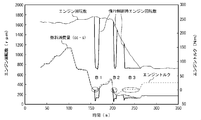
- the horizontal axis indicates time and the flow of control
- the vertical axis indicates the engine speed.
- coasting control If coasting control is not performed, the engine speed remains high as indicated by the broken line during the coasting control execution period, so that fuel is wasted, but coasting control is performed. Thus, the engine speed 72 becomes the idle speed and fuel is saved.
- the coasting control device 1 digitally samples the output signal of the accelerator opening sensor every predetermined time, and detects the accelerator opening that uses the moving average value as the accelerator opening every predetermined time.
- the accelerator opening speed is calculated by differentiating the part 2 and the accelerator opening for a predetermined time, the accelerator opening is negative, and the absolute value is smaller than a preset start reference value, The boundary between the negative condition where the engine output torque is negative and the positive area where the engine output torque is positive, with the determination condition detection unit 3 permitting the determination of coasting control start and the accelerator opening and the clutch rotational speed as indices.
- the coasting control determination map 4 in which the coasting control threshold line is set along the engine output torque zero line (no-load line) and the coasting control start determination are permitted.
- a coasting control execution determination unit 5 that starts coasting control when the coordinate point of the accelerator opening and the clutch rotational speed passes through the coasting control threshold line in the direction in which the accelerator opening decreases on the constant map 4 is provided. Yes.
- the clutch rotational speed is the rotational speed of the driven side of the clutch, and is the same as the rotational speed of the input shaft of the transmission.
- a clutch rotational speed sensor is provided on the input shaft, and the clutch rotational speed is detected from the rotational speed of the input shaft.
- the accelerator opening detection unit 2, the determination condition detection unit 3, the coasting control determination map 4, and the coasting control execution determination unit 5 are preferably mounted on the electronic control unit 11.
- Fig. 4 shows the coasting control determination map 4 as a graph image.
- the coasting control determination map 4 is created by measuring in advance the correlation between the accelerator opening and the clutch rotational speed for the engine in the clutch disengaged state.
- the coasting control determination map 4 is a map in which the horizontal axis is the accelerator opening and the vertical axis is the clutch rotational speed.
- the coasting control determination map 4 can be divided into a minus region M where the engine output torque is negative and a plus region P where the engine output torque is positive. That is, the minus region M is a region where the engine friction is larger than the engine required torque and the engine output torque is negative.
- the positive region P is a region where the engine output torque is positive because the engine required torque is larger than the engine friction.
- An engine output torque zero line (no-load line) Z that is a boundary between the minus region M and the plus region P indicates that the engine does not work to the outside and fuel is wasted.
- the coasting control threshold line T is set slightly to the left of the engine output torque zero line Z of the coasting control determination map 4 (on the side where the accelerator opening is small).
- a coasting controllable area CA having a finite width including the coasting control threshold line T is set between the minus area M and the plus area P.
- a lower limit threshold line U of the clutch rotational speed is set.
- the lower limit threshold line U defines the lower limit threshold value of the clutch rotational speed regardless of the accelerator opening.
- the lower limit threshold line U is set slightly higher than the clutch rotational speed in the idle state as shown in the figure.
- the coasting control device 1 starts coasting control when all the following four coasting start conditions are satisfied.
- the accelerator pedal operation speed is within the threshold range.
- the coasting control determination map 4 passes the coasting control threshold line T in the accelerator return direction.
- the plot point on the coasting control determination map 4 is coasting control.
- the coasting control device 1 is configured to end coasting control when at least one of the following two coasting termination conditions is satisfied.
- the accelerator pedal operating speed is outside the threshold range.
- the plot point on the coasting control determination map 4 is outside the coasting control possible area CA.
- coasting control shall not be performed.
- the engine speed transitions in the range of 1600 to 1700 rpm from about 30 s to about 200 s, and decreases from about 1700 rpm to about 700 rpm (idle speed) between about 200 s and about 260 s. .
- the engine torque increased from about 30 s to about 100 s, but then turned to decrease and continued to decrease to about 150 s.
- the engine torque is approximately 0 Nm at three locations from about 150 s to about 160 s (ellipse B1), from about 200 s to about 210 s (ellipse B2), and from about 220 s to about 260 s (ellipse B3).
- the fuel consumption (no vertical axis scale; for convenience, it is arranged so as to overlap with the engine torque) changes from about 50 s to about 200 s almost accompanying the transition of the engine torque. Even if the engine torque is approximately 0 Nm, the fuel consumption is not zero.
- coasting control the engine speed is controlled to the idle speed during a period in which the engine torque is approximately 0 Nm.
- the graph shows the engine speed line during thick coasting control (thick solid line) so as to be separated from the engine rotational speed line without solid coasting control (solid line).
- the coasting control was executed three times for ellipses B1, B2 and B3.
- the fuel consumption amount in the period when the coasting control is performed is lower than the fuel consumption amount when the coasting control is not performed, and it is understood that the fuel consumption is saved.
- FIG. 6 shows a coasting control determination map 100 in which coasting control is actually performed. Each point shows a plot point of the actually detected accelerator opening and clutch rotational speed.
- a negative region, a positive region, a coasting control threshold line (acceleration 0 threshold point, deceleration 0 threshold point), and a coasting controllable region are set.
- coasting control apparatus 1 discharges the amount of operating oil corresponding to the amount of depression of clutch pedal 52 from clutch-free operating cylinder 54 when clutch pedal 52 is depressed during coasting control.
- a clutch control unit 6 for controlling the clutch-free actuator unit 55 is further provided.
- the clutch control unit 6 obtains the amount of operating oil to be discharged from the intermediate cylinder chamber 61a according to the depression amount of the clutch pedal 52 measured by the clutch pedal depression amount sensor 13, and the amount of the obtained amount is determined.
- the solenoid valve 62 of the clutch-free actuator unit 55 is controlled so that the operating oil is discharged from the intermediate cylinder chamber 61a.
- the clutch control unit 6 is mounted on the electronic control unit 11 in the same manner as the accelerator opening detection unit 2, the determination condition detection unit 3, the coasting control determination map 4, and the coasting control execution determination unit 5.
- the clutch control unit 6 may be mounted on a unit other than the electronic control unit 11 (for example, the ECM 12), and the accelerator opening degree detection unit 2, the determination condition detection unit 3, the coasting control determination map 4, and the coasting control It may be mounted on a unit different from the unit on which the execution determination unit 5 is mounted.
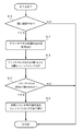
- the clutch control unit 6 first determines whether coasting control is being performed (step S1). If it is determined in step S1 that coasting control is not being performed (NO), the process ends.
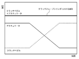
- step S2 If it is determined in step S1 that coasting control is being performed (YES), the clutch control unit 6 reads the depression amount of the clutch pedal 52 from the clutch pedal depression amount sensor 13 (step S2). As shown in FIG. 8, during coasting control, operating oil is supplied to the intermediate cylinder chamber 61a by the clutch-free actuator unit 55, and the secondary piston 67 is in a state of being stroked to the left side in the drawing, and the clutch slave cylinder 56 The piston 56a is stroked to the right in the figure, and the clutch 58 is disengaged.
- the clutch control unit 6 determines the amount of operating oil to be discharged from the intermediate cylinder chamber 61a based on the depression amount of the clutch pedal 52 read in step S2, and controls the solenoid valve 62 with the determined amount of operating oil.
- the intermediate cylinder chamber 61a is then discharged (step S3).
- the pedal-side cylinder chamber 61b is obtained by multiplying the depression amount of the clutch pedal 52 by a predetermined coefficient.
- the amount of operating oil supplied to the engine can be determined.
- the solenoid valve 62 is controlled so that the amount of operating oil equal to the amount of operating oil supplied to the pedal side cylinder chamber 61b by operating the clutch pedal 52 is discharged from the intermediate cylinder chamber 61a.
- the method of obtaining the amount of operating oil to be discharged from the intermediate cylinder chamber 61a is not limited to this.
- a map of the amount of operating oil to be discharged from the intermediate cylinder chamber 61a with respect to the depression amount of the clutch pedal 52 is created in advance.
- the amount of operating oil discharged from the intermediate cylinder chamber 61a may be obtained using the map.
- step S4 determines whether or not the clutch pedal 52 has been fully depressed (step S4), and if it is determined that the clutch pedal 52 has been fully depressed (YES), the solenoid valve 62 is opened. All the operating oil in the intermediate cylinder chamber 61a is discharged (step S5), and the process is terminated. If it is determined in step S4 that the clutch pedal 52 has not been fully depressed (NO), the process is terminated.
- the coasting control device 1 when the clutch pedal 52 is depressed during coasting control, the amount of operating oil corresponding to the depression amount of the clutch pedal 52 is reduced to the clutch-free operating cylinder 54.
- a clutch control unit 6 that controls the clutch-free actuator unit 55 so as to be discharged.
- the amount of operating oil discharged from the intermediate cylinder chamber 61a is obtained according to the depression amount of the clutch pedal 52 measured by the clutch pedal depression amount sensor 13, and the obtained amount of working oil is supplied to the intermediate cylinder chamber 61a.
- the present invention is not limited to this, and for example, a hydraulic sensor that measures the hydraulic pressure in the intermediate cylinder chamber 61a is provided, and the solenoid valve 62 is set so that the hydraulic pressure measured by the hydraulic sensor is constant. By controlling this, the amount of operating oil corresponding to the amount of depression of the clutch pedal 52 may be discharged from the intermediate cylinder chamber 61a.
- the hydraulic pressure sensor is provided, for example, in a pipe (a pipe through which the working oil passes) that connects the intermediate cylinder chamber 61a and the solenoid valve 62.
- a pipe a pipe through which the working oil passes
- the oil pressure of the clutch slave cylinder 56 can also be kept constant, so that the same effect as the coasting control device 1 described above can be obtained.
Landscapes
- Engineering & Computer Science (AREA)
- General Engineering & Computer Science (AREA)
- Mechanical Engineering (AREA)
- Chemical & Material Sciences (AREA)
- Combustion & Propulsion (AREA)
- Physics & Mathematics (AREA)
- Fluid Mechanics (AREA)
- Hydraulic Clutches, Magnetic Clutches, Fluid Clutches, And Fluid Joints (AREA)
Abstract
Description
(1)アクセルペダルの操作速度がしきい値範囲内
(2)惰行制御判定マップ4において惰行制御しきい線Tをアクセル戻し方向で通過
(3)惰行制御判定マップ4へのプロット点が惰行制御可能領域CA内
(4)惰行制御判定マップ4においてクラッチ回転数が下限しきい線U以上
(1)アクセルペダルの操作速度がしきい値範囲外
(2)惰行制御判定マップ4へのプロット点が惰行制御可能領域CA外
2 アクセル開度検出部
3 判定条件検出部
4 惰行制御判定マップ
5 惰行制御実行判定部
6 クラッチ制御部
13 クラッチペダル踏み込み量センサ
52 クラッチペダル
55 クラッチフリーアクチュエータユニット(アクチュエータ)
Claims (3)
- クラッチペダルの踏み込み、あるいはアクチュエータの制御により動作油が供給され、当該供給される動作油の量に応じてクラッチを断接するクラッチシステムを備えた車両に搭載され、
前記車両の走行中にエンジンが外部に対して仕事をしないときに、前記アクチュエータによりクラッチを断にすると共に、エンジン回転数をアイドル回転数に落とす惰行制御を行う惰行制御装置において、
惰行制御中に前記クラッチペダルが踏み込まれたとき、該クラッチペダルの踏み込み量に応じた量の前記供給された動作油が前記アクチュエータから排出されるように制御するクラッチ制御部を備えたことを特徴とする惰行制御装置。 - 前記クラッチペダルの踏み込み量を測定するクラッチペダル踏み込み量センサを備え、
前記クラッチシステムは、
直列配置されたプライマリピストンとセカンダリピストンとを有するクラッチフリーオペレーティングシリンダと、
前記プライマリピストンと前記セカンダリピストンとの間のシリンダ室である中間シリンダ室に動作油を供給する油圧ポンプと、前記中間シリンダ室から排出する動作油の量を制御するソレノイドバルブとを有する前記アクチュエータと、を備え、
前記クラッチ制御部は、前記クラッチペダル踏み込み量センサで測定した前記クラッチペダルの踏み込み量に応じて、前記中間シリンダ室から排出させる動作油の量を求め、当該求めた量の動作油を前記中間シリンダ室から排出させるように、前記アクチュエータの前記ソレノイドバルブを制御する請求項1記載の惰行制御装置。 - 前記クラッチシステムは、
直列配置されたプライマリピストンとセカンダリピストンとを有するクラッチフリーオペレーティングシリンダと、
前記プライマリピストンと前記セカンダリピストンとの間のシリンダ室である中間シリンダ室に動作油を供給する油圧ポンプと、前記中間シリンダ室から排出する動作油の量を制御するソレノイドバルブとを有する前記アクチュエータと、を備え、
前記中間シリンダ室における動作油の油圧を測定する油圧センサを備え、
前記クラッチ制御部は、前記油圧センサが測定する油圧が一定となるように、前記アクチュエータの前記ソレノイドバルブを制御することで、前記クラッチペダルの踏み込み量に応じた量の動作油を前記中間シリンダ室から排出するようにされる請求項1記載の惰行制御装置。
Priority Applications (4)
| Application Number | Priority Date | Filing Date | Title |
|---|---|---|---|
| EP11800996.8A EP2589830B1 (en) | 2010-07-02 | 2011-07-01 | Coasting control device |
| CN201180032256.5A CN102959268B (zh) | 2010-07-02 | 2011-07-01 | 滑行控制装置 |
| US13/807,787 US8781700B2 (en) | 2010-07-02 | 2011-07-01 | Coasting control device |
| AU2011272220A AU2011272220B2 (en) | 2010-07-02 | 2011-07-01 | Coasting control device |
Applications Claiming Priority (2)
| Application Number | Priority Date | Filing Date | Title |
|---|---|---|---|
| JP2010-152125 | 2010-07-02 | ||
| JP2010152125A JP5620169B2 (ja) | 2010-07-02 | 2010-07-02 | 惰行制御装置 |
Publications (1)
| Publication Number | Publication Date |
|---|---|
| WO2012002534A1 true WO2012002534A1 (ja) | 2012-01-05 |
Family
ID=45402236
Family Applications (1)
| Application Number | Title | Priority Date | Filing Date |
|---|---|---|---|
| PCT/JP2011/065182 Ceased WO2012002534A1 (ja) | 2010-07-02 | 2011-07-01 | 惰行制御装置 |
Country Status (6)
| Country | Link |
|---|---|
| US (1) | US8781700B2 (ja) |
| EP (1) | EP2589830B1 (ja) |
| JP (1) | JP5620169B2 (ja) |
| CN (1) | CN102959268B (ja) |
| AU (1) | AU2011272220B2 (ja) |
| WO (1) | WO2012002534A1 (ja) |
Cited By (1)
| Publication number | Priority date | Publication date | Assignee | Title |
|---|---|---|---|---|
| WO2014163111A1 (ja) * | 2013-04-02 | 2014-10-09 | 株式会社Osamu-Factory | 後付自動クラッチ装置 |
Families Citing this family (9)
| Publication number | Priority date | Publication date | Assignee | Title |
|---|---|---|---|---|
| JP5469010B2 (ja) * | 2010-07-30 | 2014-04-09 | いすゞ自動車株式会社 | 惰行制御装置 |
| CN104514822A (zh) * | 2014-10-08 | 2015-04-15 | 李家涛 | 一种汽车电控自动离合器 |
| CN104590011B (zh) * | 2014-12-30 | 2018-09-11 | 浙江正奥汽配有限公司 | 车辆滑行控制系统及控制方法 |
| CN104590012B (zh) * | 2014-12-30 | 2018-10-02 | 浙江正奥汽配有限公司 | 车辆滑行控制系统及其离合机构 |
| KR102324757B1 (ko) * | 2017-05-02 | 2021-11-10 | 현대자동차주식회사 | 차량용 클러치 제어방법 |
| JP2020008034A (ja) * | 2018-07-03 | 2020-01-16 | トヨタ自動車株式会社 | クラッチの断接装置 |
| IT201900007404A1 (it) * | 2019-05-28 | 2020-11-28 | Bcs Spa | Metodo di funzionamento di una frizione di un trattore e trattore con frizione servoassistita |
| JP7276374B2 (ja) | 2021-03-22 | 2023-05-18 | いすゞ自動車株式会社 | 格納箱状態特定システム |
| JP7476914B2 (ja) * | 2022-02-02 | 2024-05-01 | トヨタ自動車株式会社 | 車両 |
Citations (3)
| Publication number | Priority date | Publication date | Assignee | Title |
|---|---|---|---|---|
| JPH0867175A (ja) | 1994-08-31 | 1996-03-12 | Suzuki Motor Corp | エンジンの制御装置 |
| JP2006342832A (ja) | 2005-06-07 | 2006-12-21 | Isuzu Motors Ltd | 走行体の制御装置及び制御方法 |
| JP2007205445A (ja) * | 2006-02-01 | 2007-08-16 | Aisin Seiki Co Ltd | 油圧脈動吸収装置 |
Family Cites Families (5)
| Publication number | Priority date | Publication date | Assignee | Title |
|---|---|---|---|---|
| JPS6060334A (ja) * | 1983-09-13 | 1985-04-06 | Isuzu Motors Ltd | クラツチ操作装置 |
| EP0798480B1 (en) * | 1996-03-31 | 2000-07-12 | Isuzu Motors Limited | Automatic clutch unit for vehicle use |
| JPH11247890A (ja) * | 1998-02-27 | 1999-09-14 | Isuzu Motors Ltd | 半クラッチストローク値の特定方法及び異常診断方法 |
| DE102004015185A1 (de) * | 2004-03-24 | 2005-10-27 | Fte Automotive Gmbh & Co. Kg | Hydraulische Betätigungsvorrichtung für eine Kraftfahrzeug-Reibkupplung |
| JP5462092B2 (ja) * | 2010-07-02 | 2014-04-02 | いすゞ自動車株式会社 | 惰行制御装置 |
-
2010
- 2010-07-02 JP JP2010152125A patent/JP5620169B2/ja not_active Expired - Fee Related
-
2011
- 2011-07-01 EP EP11800996.8A patent/EP2589830B1/en active Active
- 2011-07-01 AU AU2011272220A patent/AU2011272220B2/en not_active Ceased
- 2011-07-01 WO PCT/JP2011/065182 patent/WO2012002534A1/ja not_active Ceased
- 2011-07-01 CN CN201180032256.5A patent/CN102959268B/zh active Active
- 2011-07-01 US US13/807,787 patent/US8781700B2/en active Active
Patent Citations (3)
| Publication number | Priority date | Publication date | Assignee | Title |
|---|---|---|---|---|
| JPH0867175A (ja) | 1994-08-31 | 1996-03-12 | Suzuki Motor Corp | エンジンの制御装置 |
| JP2006342832A (ja) | 2005-06-07 | 2006-12-21 | Isuzu Motors Ltd | 走行体の制御装置及び制御方法 |
| JP2007205445A (ja) * | 2006-02-01 | 2007-08-16 | Aisin Seiki Co Ltd | 油圧脈動吸収装置 |
Non-Patent Citations (1)
| Title |
|---|
| See also references of EP2589830A4 |
Cited By (1)
| Publication number | Priority date | Publication date | Assignee | Title |
|---|---|---|---|---|
| WO2014163111A1 (ja) * | 2013-04-02 | 2014-10-09 | 株式会社Osamu-Factory | 後付自動クラッチ装置 |
Also Published As
| Publication number | Publication date |
|---|---|
| CN102959268B (zh) | 2015-06-03 |
| JP2012013187A (ja) | 2012-01-19 |
| EP2589830A1 (en) | 2013-05-08 |
| JP5620169B2 (ja) | 2014-11-05 |
| EP2589830B1 (en) | 2019-09-04 |
| CN102959268A (zh) | 2013-03-06 |
| US20130103275A1 (en) | 2013-04-25 |
| US8781700B2 (en) | 2014-07-15 |
| AU2011272220B2 (en) | 2014-06-19 |
| AU2011272220A1 (en) | 2013-02-07 |
| EP2589830A4 (en) | 2018-03-28 |
Similar Documents
| Publication | Publication Date | Title |
|---|---|---|
| JP5620169B2 (ja) | 惰行制御装置 | |
| JP5694693B2 (ja) | 惰行制御装置 | |
| AU2011283966B2 (en) | Coasting control device | |
| JP5469010B2 (ja) | 惰行制御装置 | |
| JP5278134B2 (ja) | 惰行制御装置 | |
| JP5545736B2 (ja) | 惰行制御装置 | |
| JP5778396B2 (ja) | 惰行制御装置 | |
| JP5628587B2 (ja) | 惰行制御装置 | |
| JP5321223B2 (ja) | 燃費走行制御時の補助制御装置 | |
| JP5602522B2 (ja) | 惰行制御装置 | |
| JP5462101B2 (ja) | 惰行制御装置 | |
| JP5546988B2 (ja) | 惰行制御装置 | |
| JP2012013186A (ja) | 惰行制御装置 | |
| JP5462103B2 (ja) | 惰行制御装置 | |
| JP5602533B2 (ja) | 惰行制御装置 | |
| JP5462092B2 (ja) | 惰行制御装置 | |
| JP5332888B2 (ja) | 燃費走行制御時の補助制御装置 | |
| JP5616155B2 (ja) | 惰行制御装置 | |
| JP5240062B2 (ja) | 惰行制御装置 | |
| JP5462102B2 (ja) | 惰行制御装置 |
Legal Events
| Date | Code | Title | Description |
|---|---|---|---|
| WWE | Wipo information: entry into national phase |
Ref document number: 201180032256.5 Country of ref document: CN |
|
| 121 | Ep: the epo has been informed by wipo that ep was designated in this application |
Ref document number: 11800996 Country of ref document: EP Kind code of ref document: A1 |
|
| WWE | Wipo information: entry into national phase |
Ref document number: 13807787 Country of ref document: US |
|
| NENP | Non-entry into the national phase |
Ref country code: DE |
|
| WWE | Wipo information: entry into national phase |
Ref document number: 2011800996 Country of ref document: EP |
|
| ENP | Entry into the national phase |
Ref document number: 2011272220 Country of ref document: AU Date of ref document: 20110701 Kind code of ref document: A |