WO2012007998A1 - 燃料電池 - Google Patents
燃料電池 Download PDFInfo
- Publication number
- WO2012007998A1 WO2012007998A1 PCT/JP2010/004609 JP2010004609W WO2012007998A1 WO 2012007998 A1 WO2012007998 A1 WO 2012007998A1 JP 2010004609 W JP2010004609 W JP 2010004609W WO 2012007998 A1 WO2012007998 A1 WO 2012007998A1
- Authority
- WO
- WIPO (PCT)
- Prior art keywords
- gas
- flow path
- gas flow
- fuel cell
- recovery
- Prior art date
- Legal status (The legal status is an assumption and is not a legal conclusion. Google has not performed a legal analysis and makes no representation as to the accuracy of the status listed.)
- Ceased
Links
Images


Classifications
-
- H—ELECTRICITY
- H01—ELECTRIC ELEMENTS
- H01M—PROCESSES OR MEANS, e.g. BATTERIES, FOR THE DIRECT CONVERSION OF CHEMICAL ENERGY INTO ELECTRICAL ENERGY
- H01M8/00—Fuel cells; Manufacture thereof
- H01M8/04—Auxiliary arrangements, e.g. for control of pressure or for circulation of fluids
- H01M8/04082—Arrangements for control of reactant parameters, e.g. pressure or concentration
- H01M8/04089—Arrangements for control of reactant parameters, e.g. pressure or concentration of gaseous reactants
- H01M8/04104—Regulation of differential pressures
-
- H—ELECTRICITY
- H01—ELECTRIC ELEMENTS
- H01M—PROCESSES OR MEANS, e.g. BATTERIES, FOR THE DIRECT CONVERSION OF CHEMICAL ENERGY INTO ELECTRICAL ENERGY
- H01M8/00—Fuel cells; Manufacture thereof
- H01M8/02—Details
- H01M8/0202—Collectors; Separators, e.g. bipolar separators; Interconnectors
- H01M8/0258—Collectors; Separators, e.g. bipolar separators; Interconnectors characterised by the configuration of channels, e.g. by the flow field of the reactant or coolant
- H01M8/026—Collectors; Separators, e.g. bipolar separators; Interconnectors characterised by the configuration of channels, e.g. by the flow field of the reactant or coolant characterised by grooves, e.g. their pitch or depth
-
- H—ELECTRICITY
- H01—ELECTRIC ELEMENTS
- H01M—PROCESSES OR MEANS, e.g. BATTERIES, FOR THE DIRECT CONVERSION OF CHEMICAL ENERGY INTO ELECTRICAL ENERGY
- H01M8/00—Fuel cells; Manufacture thereof
- H01M8/04—Auxiliary arrangements, e.g. for control of pressure or for circulation of fluids
- H01M8/04082—Arrangements for control of reactant parameters, e.g. pressure or concentration
- H01M8/04089—Arrangements for control of reactant parameters, e.g. pressure or concentration of gaseous reactants
- H01M8/04119—Arrangements for control of reactant parameters, e.g. pressure or concentration of gaseous reactants with simultaneous supply or evacuation of electrolyte; Humidifying or dehumidifying
- H01M8/04156—Arrangements for control of reactant parameters, e.g. pressure or concentration of gaseous reactants with simultaneous supply or evacuation of electrolyte; Humidifying or dehumidifying with product water removal
-
- H—ELECTRICITY
- H01—ELECTRIC ELEMENTS
- H01M—PROCESSES OR MEANS, e.g. BATTERIES, FOR THE DIRECT CONVERSION OF CHEMICAL ENERGY INTO ELECTRICAL ENERGY
- H01M8/00—Fuel cells; Manufacture thereof
- H01M8/10—Fuel cells with solid electrolytes
- H01M8/1004—Fuel cells with solid electrolytes characterised by membrane-electrode assemblies [MEA]
-
- H—ELECTRICITY
- H01—ELECTRIC ELEMENTS
- H01M—PROCESSES OR MEANS, e.g. BATTERIES, FOR THE DIRECT CONVERSION OF CHEMICAL ENERGY INTO ELECTRICAL ENERGY
- H01M8/00—Fuel cells; Manufacture thereof
- H01M8/24—Grouping of fuel cells, e.g. stacking of fuel cells
- H01M8/241—Grouping of fuel cells, e.g. stacking of fuel cells with solid or matrix-supported electrolytes
-
- H—ELECTRICITY
- H01—ELECTRIC ELEMENTS
- H01M—PROCESSES OR MEANS, e.g. BATTERIES, FOR THE DIRECT CONVERSION OF CHEMICAL ENERGY INTO ELECTRICAL ENERGY
- H01M8/00—Fuel cells; Manufacture thereof
- H01M8/24—Grouping of fuel cells, e.g. stacking of fuel cells
- H01M8/2457—Grouping of fuel cells, e.g. stacking of fuel cells with both reactants being gaseous or vaporised
-
- H—ELECTRICITY
- H01—ELECTRIC ELEMENTS
- H01M—PROCESSES OR MEANS, e.g. BATTERIES, FOR THE DIRECT CONVERSION OF CHEMICAL ENERGY INTO ELECTRICAL ENERGY
- H01M8/00—Fuel cells; Manufacture thereof
- H01M8/24—Grouping of fuel cells, e.g. stacking of fuel cells
- H01M8/2465—Details of groupings of fuel cells
- H01M8/2483—Details of groupings of fuel cells characterised by internal manifolds
-
- H—ELECTRICITY
- H01—ELECTRIC ELEMENTS
- H01M—PROCESSES OR MEANS, e.g. BATTERIES, FOR THE DIRECT CONVERSION OF CHEMICAL ENERGY INTO ELECTRICAL ENERGY
- H01M8/00—Fuel cells; Manufacture thereof
- H01M8/10—Fuel cells with solid electrolytes
- H01M2008/1095—Fuel cells with polymeric electrolytes
-
- H—ELECTRICITY
- H01—ELECTRIC ELEMENTS
- H01M—PROCESSES OR MEANS, e.g. BATTERIES, FOR THE DIRECT CONVERSION OF CHEMICAL ENERGY INTO ELECTRICAL ENERGY
- H01M8/00—Fuel cells; Manufacture thereof
- H01M8/02—Details
- H01M8/0202—Collectors; Separators, e.g. bipolar separators; Interconnectors
- H01M8/0267—Collectors; Separators, e.g. bipolar separators; Interconnectors having heating or cooling means, e.g. heaters or coolant flow channels
-
- Y—GENERAL TAGGING OF NEW TECHNOLOGICAL DEVELOPMENTS; GENERAL TAGGING OF CROSS-SECTIONAL TECHNOLOGIES SPANNING OVER SEVERAL SECTIONS OF THE IPC; TECHNICAL SUBJECTS COVERED BY FORMER USPC CROSS-REFERENCE ART COLLECTIONS [XRACs] AND DIGESTS
- Y02—TECHNOLOGIES OR APPLICATIONS FOR MITIGATION OR ADAPTATION AGAINST CLIMATE CHANGE
- Y02E—REDUCTION OF GREENHOUSE GAS [GHG] EMISSIONS, RELATED TO ENERGY GENERATION, TRANSMISSION OR DISTRIBUTION
- Y02E60/00—Enabling technologies; Technologies with a potential or indirect contribution to GHG emissions mitigation
- Y02E60/30—Hydrogen technology
- Y02E60/50—Fuel cells
Definitions
- the present invention relates to a fuel cell that generates electricity electrochemically using a reaction gas, and more particularly, to a gas flow path for flowing a reaction gas inside the fuel cell.
- MEA membrane electrode assemblies
- electrode layers are bonded to both surfaces of an electrolyte membrane, and a separator that separates each of these membrane electrode assemblies. It is known that gas layers that are alternately stacked and a reaction gas flow is formed on the electrode surface of the MEA by a separator.
- the supply flow path that communicates with the reaction gas supply side and the recovery flow path that communicates with the reaction gas recovery side are each comb-like.
- a fuel cell formed so as to be engaged with each other for example, Patent Document 1.
- the generated water generated in the supply channel due to power generation moves to and stays in the closed region of the tip of the comb-shaped supply channel. Since the retained generated water hinders the supply of the reaction gas to the MEA, there is a problem that the power generation performance is deteriorated.
- the present invention aims to provide a technique for improving the power generation performance of a fuel cell based on the above-described problems.
- the present invention has been made to solve at least a part of the problems described above, and can be realized as the following forms or application examples.
- the fuel cell of Application Example 1 is a fuel cell, and a membrane electrode assembly in which an electrode layer is bonded to both surfaces of an electrolyte membrane and an array arranged side by side on at least one surface of the membrane electrode assembly
- a plurality of gas flow paths for flowing the reaction gas to the membrane electrode assembly from the reaction gas supply side toward the recovery side, and the plurality of gas flow paths are provided between the supply side and the recovery side. It includes a first gas channel that is a gas channel that communicates with each other, and a second gas channel that is a gas channel closed on the supply side.
- the reaction gas is moved from the supply side of the first gas flow path to the second gas flow path while being hidden, and generated on the recovery side of the first gas flow path. Water retention can be suppressed.
- the gas diffusion performance for diffusing the reaction gas to the membrane electrode assembly can be improved on the supply side in the plurality of gas flow paths, and the gas diffusion due to the retention of the generated water on the recovery side in the plurality of gas flow paths. A decrease in performance can be suppressed. As a result, the power generation performance of the fuel cell can be improved.
- the plurality of gas flow paths are provided on the anode side of the membrane electrode assembly, and face the direction of the oxidizing gas on the cathode side of the membrane electrode assembly Therefore, it is preferable to flow fuel gas to the anode side.
- the fuel gas is compared on the anode side on the downstream side of the cathode side by moving the membrane electrode assembly from the supply side of the first gas channel to the second gas channel. It is possible to humidify the fuel gas using a large amount of moisture.
- the membrane electrode assembly includes a diffusion layer that diffuses the reaction gas flowing through the plurality of gas flow paths into the electrode layer,
- the air permeability which is the degree to which the reaction gas permeates on the recovery side, is preferably larger than that on the supply side of the diffusion layer. According to the fuel cell of Application Example 3, it is possible to improve the gas diffusion performance on the recovery side in the plurality of gas flow paths.
- the thickness of the microporous layer on the collection side of the diffusion layer may be smaller than that on the supply side of the diffusion layer. Therefore, it is possible to easily realize a diffusion layer having a larger air permeability on the collection side than on the supply side.
- the diffusion layer includes a first diffusion layer provided on the supply side, and a second diffusion layer provided on the recovery side and having a larger air permeability than the first diffusion layer. May be included. Thereby, it is possible to easily realize a diffusion layer having a larger air permeability on the collection side than on the supply side.
- the compressive stress in the thickness direction on the recovery side of the diffusion layer may be smaller than that on the supply side of the diffusion layer. Therefore, it is possible to easily realize a diffusion layer having a larger air permeability on the collection side than on the supply side.
- the fuel cell according to any one of Application Examples 1 to 3 is further provided with a recovery flow path for recovering a reaction gas from the plurality of gas flow paths, and protruding from the recovery flow path.
- the pressure on the recovery side of the first gas flow path is increased more than the pressure on the recovery side of the second gas flow path, whereby the reaction gas is recovered on the recovery side of the first gas flow path.
- the membrane electrode assembly can be submerged and flowed to the second gas flow path. Thereby, the gas diffusion performance on the collection side in the plurality of gas flow paths can be improved.
- the plurality of gas flow paths may be configured by alternately arranging the first gas flow paths and the second gas flow paths. good. According to the fuel cell of Application Example 5, in a plurality of gas flow paths, it is possible to uniformly achieve improvement in gas diffusion performance on the supply side and suppression of retention of generated water on the recovery side.
- the plurality of gas flow paths may further include a third gas flow path that is a gas flow path with the recovery side blocked. good.
- the reaction gas can be moved from the recovery side of the third gas channel to the second gas channel while the membrane electrode assembly is hidden. Thereby, the gas diffusion performance on the collection side in the plurality of gas flow paths can be improved.
- the plurality of the plurality of gas cells may be arranged repeatedly in the order of the first gas channel, the second gas channel, the third gas channel, and the second gas channel.
- a gas flow path may be configured. According to the fuel cell of Application Example 7, in a plurality of gas flow paths, improvement in gas diffusion performance on the supply side and recovery side and suppression of retention of generated water on the recovery side can be realized uniformly. .
- the form of the present invention is not limited to the fuel cell, and may be applied to various forms such as a vehicle that travels using the power of the fuel cell, a power generation system that supplies the power of the fuel cell, and a method for manufacturing the fuel cell. It is also possible to do. Further, the present invention is not limited to the above-described embodiments, and it is needless to say that the present invention can be implemented in various forms without departing from the spirit of the present invention.
- FIG. 1 is an explanatory diagram showing the configuration of the fuel cell 10.
- the fuel cell 10 generates electricity electrochemically using a reaction gas.
- the fuel cell 10 is a solid polymer type fuel cell, and uses a fuel gas containing hydrogen and an oxidizing gas containing oxygen as reaction gases.
- the fuel gas used in the fuel cell 10 is hydrogen gas stored in a storage tank. However, in other embodiments, it may be hydrogen gas stored in a hydrogen storage alloy or carbonized. Hydrogen gas obtained by reforming a hydrogen fuel may be used.
- the oxidizing gas used in the fuel cell 10 is air taken from outside air.
- the fuel cell 10 includes a plurality of cells 15 that perform an electrochemical reaction that directly extracts electricity from a reaction gas, and the plurality of cells 15 are stacked on each other.
- the cell 15 of the fuel cell 10 includes a membrane electrode assembly (MEA) 20, an anode separator 30, and a cathode separator 50.
- MEA 20 is sandwiched between the anode separator 30 and the cathode separator 50.
- the MEA 20 of the fuel cell 10 includes an electrolyte membrane 210, an anode electrode 230, and a cathode electrode 250.
- the anode electrode 230 of the MEA 20 includes an anode catalyst layer 231 and an anode diffusion layer 235
- the cathode electrode 250 of the MEA 20 includes a cathode catalyst layer 251 and a cathode diffusion layer 255.
- An anode electrode 230 is bonded to one surface of the electrolyte membrane 210 by laminating an anode catalyst layer 231 and an anode diffusion layer 235 in this order.
- the cathode electrode 250 is bonded to the other surface of the electrolyte membrane 210 by laminating the cathode catalyst layer 251 and the cathode diffusion layer 255 in this order.
- the electrolyte membrane 210 of the MEA 20 is a proton conductor having proton conductivity, and is a perfluorosulfonic acid ion exchange membrane using an ionomer resin in this embodiment.
- the anode catalyst layer 231 and the cathode catalyst layer 251 of the MEA 20 are formed of a material having gas permeability and conductivity and supporting a catalyst (for example, platinum or platinum alloy) that promotes an electrochemical reaction between hydrogen and oxygen. In this embodiment, it is formed of a carbon support carrying a platinum-based catalyst.
- the anode diffusion layer 235 and the cathode diffusion layer 255 of the MEA 20 are formed of a material having gas permeability and conductivity.
- the anode diffusion layer 235 and the cathode diffusion layer 255 can be formed of carbon cloth or carbon paper which is a carbon porous body.
- the air permeability which is the degree to which the reaction gas permeates through the anode diffusion layer 235 and the cathode diffusion layer 255, is substantially uniform over the entire surface.
- the anode separator 30 of the fuel cell 10 has a plurality of gas passages 45 through which fuel gas flows on the surface of the anode diffusion layer 235 of the MEA 20, and the cathode separator 50 of the fuel cell 10 is the surface of the cathode diffusion layer 255 of the MEA 20.
- the anode separator 30 and the cathode separator 50 have sufficient conductivity for collecting electricity generated in the MEA 20, and have sufficient durability, heat resistance, and gas impermeability for flowing a reaction gas through the MEA 20.
- the anode separator 30 and the cathode separator 50 are made of carbon resin.
- the anode separator 30 and the cathode separator 50 may be made of stainless steel, titanium, a titanium alloy, or conductive ceramics. In this embodiment, the anode separator 30 and the cathode separator 50 are separately configured. However, in other embodiments, the anode separator 30 and the cathode separator 50 may be integrally configured.
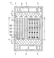
- FIG. 2 is an explanatory diagram showing a detailed configuration of the anode separator 30.
- FIG. 2 illustrates the shape of the anode separator 30 as viewed from the MEA 20 side.
- the anode separator 30 includes an outer wall portion 310, holes 311 to 316, a plurality of protrusions 322, a plurality of partition walls 350, a plurality of blocking portions 352, and a plurality of protrusions 382.
- the outer wall portion 310, the partition wall portion 350, and the blocking portion 352 of the anode separator 30 are portions that contact the anode diffusion layer 235 of the MEA 20.
- the anode separator 30 forms a supply flow path 42, a plurality of gas flow paths 45, and a recovery flow path 48 as flow paths partitioned by these portions.
- the shape of the anode separator 30 viewed from the MEA 20 side is a rectangle.
- the outer wall portion 310, the protruding portion 322, the partition wall portion 350, the closing portion 352, and the protruding portion 382 are hatched in order to facilitate shape recognition of the various flow paths formed by the anode separator 30.
- the holes 311 to 316 of the anode separator 30 form holes that penetrate the anode separator 30.
- the hole 311, the hole 312, and the hole 313 are sequentially provided along one short side of the rectangular anode separator 30, and the hole 314, the hole 315, and the hole 316 are the other of the rectangular anode separator 30.
- the hole 311 constitutes a part of a flow path for flowing fuel gas to be supplied to each of the plurality of cells 15 in the fuel cell 10
- the hole 316 is a plurality of cells in the fuel cell 10.
- 15 constitutes a part of the flow path through which the fuel gas recovered from each of the 15 flows.
- the hole 314 constitutes a part of a flow path for flowing an oxidizing gas to be supplied to each of the plurality of cells 15 in the fuel cell 10, and the hole 313 is a plurality of cells in the fuel cell 10.
- 15 constitutes a part of the flow path through which the oxidizing gas recovered from each of the 15 flows.
- the hole 312 constitutes a part of a flow path for flowing cooling water to be supplied to each of the plurality of cells 15 in the fuel cell 10
- the hole 315 is a plurality of cells in the fuel cell 10.
- 15 constitutes a part of the flow path through which the cooling water recovered from each of the 15 flows.
- the anode separator 30 and the cathode separator 50 are the same component, and the portion of the cathode separator 50 corresponding to the hole 316 of the anode separator 30 is supplied to each of the plurality of cells 15 in the fuel cell 10.
- the part of the cathode separator 50 corresponding to the hole 311 of the anode separator 30 is configured to flow the oxidizing gas recovered from each of the plurality of cells 15 in the fuel cell 10. It forms part of the road.
- the flow of the fuel gas in the plurality of gas flow paths 45 of the anode separator 30 is in a direction opposite to the flow of the oxidizing gas in the plurality of gas flow paths 65 of the cathode separator 50 with the MEA 20 interposed therebetween.
- the outer wall 310 of the anode separator 30 surrounds the power generation region 40 corresponding to the portion where power generation is performed in the MEA 20 in a state where the power generation region 40 communicates with the hole 311 and the hole 316.
- the plurality of partition walls 350 of the anode separator 30 extend to the power generation region 40 as streak-like ridges in a direction parallel to the long side of the rectangular anode separator 30 and are provided at equal intervals apart from each other.
- a plurality of gas flow paths 45 are formed between the portion 310 and the partition wall portion 350 and between the partition wall portions 350.
- the power generation region 40 is a rectangular region located at the center of the anode separator 30.
- a supply channel 42, a plurality of gas channels 45, and a recovery channel 48 are formed in this order from the hole 311 side to the hole 316 side.
- the supply flow path 42 of the anode separator 30 is formed along one side of the rectangular power generation region 40 on the hole 311 side, and distributes the fuel gas supplied from the hole 311 to each of the plurality of gas flow paths 45.
- the fuel gas is diffused into the anode diffusion layer 235 of the MEA 20 while being supplied.
- a plurality of projecting portions 322 are projected from the supply channel 42 toward the MEA 20 while being separated from each other.
- the recovery flow path 48 of the anode separator 30 is formed along one side of the rectangular power generation region 40 on the hole 316 side, and the fuel gas recovered from the plurality of gas flow paths 45 is discharged to the hole 316 while the MEA 20 The fuel gas is diffused in the anode diffusion layer 235.
- a plurality of projecting portions 382 project from the recovery channel 48 toward the MEA 20 in a state of being separated from each other in order to adjust the flow of fuel gas.
- the plurality of gas flow paths 45 of the anode separator 30 are formed between the supply flow path 42 and the recovery flow path 48 in the rectangular power generation region 40, and from the upstream portion Su on the supply flow path 42 side to the recovery flow path 48 side.
- the fuel gas is diffused in the anode diffusion layer 235 of the MEA 20 while flowing the fuel gas toward the downstream portion Sd.
- the plurality of gas flow paths 45 includes a gas flow path 45 a that is a first gas flow path that communicates between the supply flow path 42 and the recovery flow path 48, and a second flow path that is closed on the supply flow path 42 side by a closing portion 352. And a gas flow path 45b which is a gas flow path.
- the gas flow paths 45a and 45b are distinguished from each other, the gas flow paths are indicated by using symbols “45a” and “45b”, and the gas flow paths 45a and 45b are collectively referred to.
- the reference numeral “45” is used to indicate a gas flow path.
- the cross-sectional area of the gas flow channel 45 is substantially the same from the upstream portion Su to the downstream portion Sd.
- the gas flow paths 45a and the gas flow paths 45b are alternately arranged to configure the plurality of gas flow paths 45.
- at least one of the gas flow paths 45a and the gas flow paths 45b is provided. Two or more may be arranged in succession.
- the partition wall portion 350 and the closing portion 352 are integrally formed with the outer wall portion 310.
- at least one of the partition wall portion 350 and the closing portion 352 is formed as a separate member.
- the blocking portion 352 is provided at the end of the partition wall portion 350 on the supply channel 42 side.
- the closing portion 352 is not limited to this, and may be at least on the supply channel 42 side from the center of the partition wall portion 350. .
- the flow of fuel gas flowing through the power generation region 40 is illustrated using white arrows, and the flow of fuel gas that passes through the partition wall 350 and flows into the gas flow path 45 b is illustrated using black arrows. Illustrated. Since the gas flow path 45a communicates from the supply flow path 42 to the recovery flow path 48, the generated water generated in the gas flow path 45a due to power generation does not stay in the gas flow path 45a, and the recovery flow It is discharged to the path 48. On the supply flow path 42 side of the gas flow path 45b, the flow of the fuel gas is blocked by the closing portion 352, so that the partition wall 350 is dived into the gas flow path 45b through the anode diffusion layer 235 of the MEA 20 from the gas flow path 45a. Fuel gas flows in through.
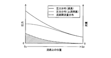
- FIG. 3 is an explanatory diagram showing the characteristics of the gas flow path 45 in the first embodiment.
- the position from the upstream portion Su to the downstream portion Sd in the gas flow path 45 is set on the horizontal axis, the pressure and flow rate of the fuel gas are set on the vertical axis, and the pressure distribution and flow in the gas flow path 45 are set.
- the flow distribution between roads is illustrated.
- the pressure distribution (communication) in FIG. 3 indicates the pressure distribution of the fuel gas flowing through the gas flow path 45a.
- the pressure distribution (upstream blockage) in FIG. 3 shows the pressure distribution of the fuel gas flowing through the gas flow path 45b.
- the flow rate distribution between the flow channels in FIG. 3 indicates the flow rate of the fuel gas that moves through the gas flow channel 45a from the gas flow channel 45a.
- the pressure of the gas flow path 45a is larger than the pressure of the gas flow path 45b in which the upstream portion Su is closed.
- the pressures in the gas flow path 45a and the gas flow path 45b decrease while narrowing the pressure difference between the two toward the downstream portion Sd, and become the same pressure in the downstream portion Sd.
- the flow rate distribution between the flow paths from the gas flow path 45a to the gas flow path 45b gradually decreases from the upstream section Su toward the downstream section Sd according to the pressure difference between the gas flow path 45a and the gas flow path 45b. To do.
- the reaction gas is moved from the supply flow path 42 side of the gas flow path 45a to the MEA 20 while moving to the gas flow path 45b, and the recovery flow of the gas flow path 45a is recovered.
- the retention of the produced water on the side of the path 48 can be suppressed.
- the gas diffusion performance of diffusing the reaction gas to the MEA 20 can be improved on the supply flow path 42 side in the plurality of gas flow paths 45, and the generated water is generated on the recovery flow path 48 side in the plurality of gas flow paths 45. It is possible to suppress a decrease in gas diffusion performance due to stagnation. As a result, the power generation performance of the fuel cell 10 can be improved.
- the plurality of gas flow paths 45 are configured by alternately arranging the gas flow paths 45a and the gas flow paths 45b, the gas diffusion performance on the supply flow path 42 side is improved and recovered in the plurality of gas flow paths 45. It is possible to uniformly realize the retention of generated water on the flow channel 48 side.
- the plurality of gas flow paths 45 flow the fuel gas to the anode side of the MEA 20 in a direction opposite to the flow of the oxidizing gas on the cathode side of the MEA 20, the fuel gas is supplied to the gas flow path 45a on the anode side.
- the fuel gas can be humidified using a relatively large amount of water downstream of the cathode side.
- FIG. 4 is an explanatory diagram showing a detailed configuration of the anode separator 30 in the second embodiment.
- FIG. 4 shows the shape of the anode separator 30 as viewed from the MEA 20 side, as in FIG.
- the anode separator 30 of the second embodiment is the same as that of the first embodiment except that the anode separator 30 includes a closing portion 354 that partitions a part of the plurality of gas flow paths 45.
- the closed portion 354 of the anode separator 30 is a portion that contacts the anode diffusion layer 235 of the MEA 20, similarly to the closed portion 352.
- a gas flow channel 45 a that is a first gas flow channel that communicates between the supply flow channel 42 and the recovery flow channel 48, and the supply flow channel 42 side is closed by a closing portion 352.
- a gas flow path 45c that is the third gas flow path with the recovery flow path 48 side closed by the closing portion 354 is provided.
- the reference numerals “45a”, “45b”, and “45c” are used to indicate the gas flow paths.
- the reference numeral “45” is used to indicate the gas flow paths.
- the cross-sectional area of the gas flow channel 45 is substantially the same from the upstream portion Su to the downstream portion Sd.
- the gas flow path 45a, the gas flow path 45b, the gas flow path 45c, and the gas flow path 45b are repeatedly arranged in this order to configure the plurality of gas flow paths 45.
- At least one of the channel 45a, the gas flow channel 45b, and the gas flow channel 45c may be continuously arranged, or the order may be changed.
- the partition wall 350, the blocking portion 352, and the blocking portion 354 are integrally formed with the outer wall portion 310.
- at least the partition wall 350, the blocking portion 352, and the blocking portion 354 are formed.
- One may be formed as a separate member.
- the blocking portion 354 is provided at the end of the partition wall 350 on the side of the recovery channel 48, but the present invention is not limited to this.
- the flow of the fuel gas flowing through the power generation region 40 is illustrated using white arrows, and the flow of the fuel gas that passes through the partition wall 350 and flows into the gas flow path 45b and the gas flow path 45c is shown in black. This is illustrated using the arrows. Since the gas flow path 45a communicates from the supply flow path 42 to the recovery flow path 48, the generated water generated in the gas flow path 45a due to power generation does not stay in the gas flow path 45a, and the recovery flow It is discharged to the path 48.
- the flow of the fuel gas is blocked by the closing portion 352, so that the partition wall 350 is dived into the gas flow path 45b through the anode diffusion layer 235 of the MEA 20 from the gas flow path 45a.
- Fuel gas flows in through. Since the flow of the fuel gas is blocked by the closing portion 354 on the recovery channel 48 side of the gas channel 45c, the recovery channel 48 side of the gas channel 45c is more than the recovery channel 48 side of the gas channel 45a. A lot of fuel gas passes through the partition wall 350 and flows into the gas flow path 45b.
- FIG. 5 is an explanatory diagram showing the characteristics of the gas flow path 45 in the second embodiment.
- the position from the upstream portion Su to the downstream portion Sd in the gas flow path 45 is set on the horizontal axis, the pressure and flow rate of the fuel gas are set on the vertical axis, and the pressure distribution and flow in the gas flow path 45 are set.
- the flow distribution between roads is illustrated.
- the pressure distribution (communication) in FIG. 5 indicates the pressure distribution of the fuel gas flowing through the gas flow path 45a.
- the pressure distribution (upstream blockage) in FIG. 5 indicates the pressure distribution of the fuel gas flowing through the gas flow path 45b.
- the pressure distribution (downstream blockage) in FIG. 5 indicates the pressure distribution of the fuel gas flowing through the gas flow path 45c.
- the flow rate distribution between the flow channels in FIG. 5 shows the flow rate of the fuel gas that moves through the gas flow channel 45a and the gas flow channel 45c from the gas flow channel 45a.
- the pressure of the gas flow path 45a is larger in the upstream portion Su than the pressure of the gas flow path 45b in which the upstream portion Su is closed.
- the pressures in the gas flow path 45a and the gas flow path 45b decrease while narrowing the pressure difference between the two toward the downstream portion Sd, and become the same pressure in the downstream portion Sd.
- the pressure of the gas flow path 45c in which the downstream portion Sd is blocked is the same pressure as that of the gas flow path 45a in the upstream portion Su, but decreases while widening the pressure difference with the gas flow path 45a toward the downstream portion Sd. In the downstream portion Sd, the pressure is higher than that of the gas flow path 45a and the gas flow path 45b.
- the flow rate distribution between the flow paths to the gas flow path 45b is compared with the flow volume distribution between the flow paths of the first embodiment because there is a pressure difference between the gas flow path 45b and the gas flow path 45c on the downstream portion Sd side. And increases on the downstream portion Sd side.
- the gas diffusion performance for diffusing the reaction gas into the MEA 20 is improved on the supply flow path 42 side in the plurality of gas flow paths 45 as in the first embodiment.
- the recovery flow path 48 side of the plurality of gas flow paths 45 it is possible to suppress a decrease in gas diffusion performance due to retention of generated water.
- the gas diffusion performance on the recovery flow channel 48 side in the plurality of gas flow channels 45 can be improved.
- the plurality of gas passages 45 are configured by repeatedly arranging the gas passage 45a, the gas passage 45b, the gas passage 45c, and the gas passage 45b in this order, the supply passage 42 in the plurality of gas passages 45 is provided.
- the gas diffusion performance on the side and the recovery channel 48 side can be improved, and the retention of the generated water on the recovery channel 48 side can be uniformly achieved.
- the fuel cell 10 of the third embodiment is the same as that of the first embodiment, except that the air permeability characteristics of the anode diffusion layer 235 of the MEA 20 are different.
- the air permeability of the anode diffusion layer 235 is substantially uniform over the entire surface.
- the recovery flow path 48 is more than the side corresponding to the supply flow path 42 of the anode separator 30. On the side corresponding to
- the thickness of the microporous layer mainly composed of a water repellent resin and a conductive material formed on the anode diffusion layer 235 is made smaller on the recovery flow channel 48 side than on the supply flow channel 42 side, An anode diffusion layer 235 having a larger air permeability on the recovery flow channel 48 side than on the supply flow channel 42 side is realized.
- a plurality of diffusion layer members having different air permeability are arranged from the supply channel 42 side to the recovery channel 48 side in ascending order of the air permeability to configure the anode diffusion layer 235, thereby supplying the supply flow. You may implement
- the thickness of at least one of the anode diffusion layer 235 and the anode separator 30 is made smaller on the recovery channel 48 side than on the supply channel 42 side, so that the anode diffusion layer 235 on the recovery channel 48 side.
- the anode diffusion layer 235 having a larger air permeability on the recovery channel 48 side than on the supply channel 42 side may be realized by reducing the compressive stress in the thickness direction on the supply channel 42 side.
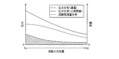
- FIG. 6 is an explanatory diagram showing the characteristics of the gas flow path 45 and the anode diffusion layer 235 in the third embodiment.
- the position from the upstream portion Su to the downstream portion Sd in the gas flow path 45 is set on the horizontal axis, the pressure and flow rate of the fuel gas, and the air permeability are set on the vertical axis.
- the pressure distribution and the flow rate distribution between the channels, and the diffusion layer air permeability distribution are illustrated.
- the pressure distribution (communication) in FIG. 6 indicates the pressure distribution of the fuel gas flowing through the gas flow path 45a.
- the pressure distribution (upstream blockage) in FIG. 6 indicates the pressure distribution of the fuel gas flowing through the gas flow path 45b.
- FIG. 6 shows the air permeability distribution of the anode diffusion layer 235.
- the flow rate distribution between the flow channels in FIG. 6 indicates the flow rate of the fuel gas that moves through the gas flow channel 45a from the gas flow channel 45a.
- the tendency of the pressure distribution in the gas channel 45a and the gas channel 45b is the same as that in the first embodiment, but the air permeability of the anode diffusion layer 235 increases from the upstream portion Su to the downstream portion Sd. Since the flow rate distribution increases toward the gas flow channel 45b, the flow channel flow distribution to the gas flow channel 45b increases on the downstream portion Sd side as compared with the flow channel flow distribution in the first embodiment.
- the gas diffusion performance for diffusing the reaction gas into the MEA 20 is improved on the supply flow path 42 side in the plurality of gas flow paths 45 as in the first embodiment.
- the recovery flow path 48 side of the plurality of gas flow paths 45 it is possible to suppress a decrease in gas diffusion performance due to retention of generated water.
- the gas diffusion performance on the recovery flow channel 48 side in the plurality of gas flow channels 45 can be improved.
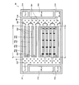
- FIG. 7 is an explanatory diagram showing a detailed configuration of the anode separator 30 in the fourth embodiment.
- FIG. 7 shows the shape of the anode separator 30 as viewed from the MEA 20 side, as in FIG.
- the anode separator 30 of the fourth embodiment is the same as that of the first embodiment except that the anode separator 30 includes a protruding portion 384 that protrudes from the recovery channel 48.
- the protrusion 384 of the anode separator 30 generates a larger pressure loss with respect to the fuel gas flowing out from the gas flow path 45a than the fuel gas flowing out from the gas flow path 45b.
- the protruding portion 384 is disposed on an extension line of the gas flow path 45a in the recovery flow path 48, has a larger elliptical column shape than the protruding portion 382, and the major axis direction thereof is the flow direction of the gas flow path 45a. They are orthogonal and the size in the major axis direction is larger than the width of the gas flow path 45a.
- the flow of the fuel gas flowing through the power generation region 40 is illustrated using white arrows, and the flow of the fuel gas that passes through the partition wall portion 350 and flows into the gas flow path 45 b and the gas flow path 45 c is illustrated in black. This is illustrated using the arrows. Since the gas flow path 45a communicates from the supply flow path 42 to the recovery flow path 48, the generated water generated in the gas flow path 45a due to power generation does not stay in the gas flow path 45a, and the recovery flow It is discharged to the path 48.
- FIG. 8 is an explanatory diagram showing the characteristics of the gas flow path 45 in the fourth embodiment.
- the position from the upstream portion Su to the downstream portion Sd in the gas flow path 45 is set on the horizontal axis, the pressure and flow rate of the fuel gas are set on the vertical axis, and the pressure distribution and flow in the gas flow path 45 are set.
- the flow distribution between roads is illustrated.
- the pressure distribution (communication) in FIG. 8 indicates the pressure distribution of the fuel gas flowing through the gas flow path 45a.
- the pressure distribution (upstream blockage) in FIG. 8 indicates the pressure distribution of the fuel gas flowing through the gas flow path 45b.
- the flow rate distribution between the flow channels in FIG. 8 indicates the flow rate of the fuel gas that moves through the gas flow channel 45a from the gas flow channel 45a.
- the pressure of the gas flow path 45a is higher in the upstream portion Su than in the gas flow path 45b in which the upstream portion Su is closed.
- the pressures in the gas flow channel 45a and the gas flow channel 45b decrease while narrowing the pressure difference between the two as it goes toward the downstream portion Sd.
- the pressure on the recovery flow path 48 side of the gas flow path 45a is larger than the pressure of the gas flow path 45b by the protruding portion 384 protruding from the recovery flow path 48.
- the inter-channel flow rate distribution to the gas channel 45b increases on the downstream portion Sd side as compared with the inter-channel flow rate distribution of the first embodiment.
- FIG. 9 is an explanatory diagram showing a detailed configuration of the anode separator 30 in the first modification of the fourth embodiment.
- the anode separator 30 of the first modification is the same as the anode separator 30 of FIG. 7 except that the shape of the protruding portion 384 is different.
- the protrusions 384 of the first modification are arranged on the extended line of the gas flow path 45a in the recovery flow path 48, and both ends of the wall surface orthogonal to the flow direction of the gas flow path 45a are bent toward the gas flow path 45b. In the same manner as the protruding portion 384 of FIG. 7, the fuel gas flowing out from the gas flow path 45a causes a larger pressure loss than the fuel gas flowing out from the gas flow path 45b.
- FIG. 10 is an explanatory diagram showing a detailed configuration of the anode separator 30 in the second modification of the fourth embodiment.
- the anode separator 30 of the second modification is the same as the anode separator 30 of FIG. 7 except that the shape of the protruding portion 384 is different.
- the projecting portion 384 of the second modified example is disposed on the extended line of the gas flow path 45a in the recovery flow path 48, and has a shape in which the apex of the “L” -shaped wall faces the gas flow path 45a. Similar to the protruding portion 384, the fuel gas flowing out from the gas flow path 45a causes a larger pressure loss than the fuel gas flowing out from the gas flow path 45b.
- the gas diffusion performance for diffusing the reaction gas into the MEA 20 is improved on the supply flow path 42 side in the plurality of gas flow paths 45 as in the first embodiment.
- the recovery flow path 48 side of the plurality of gas flow paths 45 it is possible to suppress a decrease in gas diffusion performance due to retention of generated water.
- the gas diffusion performance on the recovery flow channel 48 side in the plurality of gas flow channels 45 can be improved.
- anode diffusion layer 235 of the third embodiment may be applied to the fuel cell 10 of the second embodiment including the gas passage 45c closed on the recovery passage 48 side, or the protruding portion of the fourth embodiment. 384 may be applied.
- the cathode separator 50 is the same component as the anode separator 30 and the flow path configuration of both is the same.
- the flow path structure of the cathode separator 50 is mutually It may be a comb-shaped flow channel configuration that meshes with each other, may be a flow channel configuration formed of a porous body, or may be a flow channel configuration arranged in parallel to each other without being blocked. .
Landscapes
- Life Sciences & Earth Sciences (AREA)
- Engineering & Computer Science (AREA)
- Manufacturing & Machinery (AREA)
- Sustainable Development (AREA)
- Sustainable Energy (AREA)
- Chemical & Material Sciences (AREA)
- Chemical Kinetics & Catalysis (AREA)
- Electrochemistry (AREA)
- General Chemical & Material Sciences (AREA)
- Fuel Cell (AREA)
Abstract
Description
図1は、燃料電池10の構成を示す説明図である。燃料電池10は、反応ガスを用いて電気化学的に発電する。本実施例では、燃料電池10は、固体高分子型の燃料電池であり、水素を含有する燃料ガス、および酸素を含有する酸化ガスを反応ガスとして用いる。本実施例では、燃料電池10で用いられる燃料ガスは、貯蔵タンクに貯蔵された水素ガスであるが、他の実施形態において、水素吸蔵合金に貯蔵された水素ガスであっても良いし、炭化水素系燃料を改質して得られる水素ガスであっても良い。本実施例では、燃料電池10で用いられる酸化ガスは、外気から取り込まれた空気である。
第2実施例の燃料電池10は、アノードセパレータ30における複数のガス流路45の構成が異なる点を除き、第1実施例と同様である。図4は、第2実施例におけるアノードセパレータ30の詳細構成を示す説明図である。図4には、図2と同様に、MEA20側から見たアノードセパレータ30の形状を図示した。第2実施例のアノードセパレータ30は、複数のガス流路45の一部を区画する閉塞部354を備える点を除き、第1実施例と同様である。アノードセパレータ30の閉塞部354は、閉塞部352と同様に、MEA20のアノード拡散層235に当接する部位である。
第3実施例の燃料電池10は、MEA20のアノード拡散層235の透気度特性が異なる点を除き、第1実施例と同様である。第1実施例では、アノード拡散層235の透気度は、全面にわたって略均一であるとしたが、第3実施例では、アノードセパレータ30の供給流路42に対応する側よりも回収流路48に対応する側で大きくなる。
第4実施例の燃料電池10は、アノードセパレータ30における回収流路48の構成が異なる点を除き、第1実施例と同様である。図7は、第4実施例におけるアノードセパレータ30の詳細構成を示す説明図である。図7には、図2と同様に、MEA20側から見たアノードセパレータ30の形状を図示した。第4実施例のアノードセパレータ30は、回収流路48に突設された突出部384を備える点を除き、第1実施例と同様である。アノードセパレータ30の突出部384は、ガス流路45aから流出す燃料ガスに対して、ガス流路45bから流出する燃料ガスよりも大きな圧力損失を発生させる。本実施例では、突出部384は、回収流路48におけるガス流路45aの延長線上に配置され、突出部382よりも大きな楕円柱状であり、その長軸方向はガス流路45aの流れ方向に直交し、長軸方向の大きさはガス流路45aの幅よりも大きい。
以上、本発明の実施の形態について説明したが、本発明はこうした実施の形態に何ら限定されるものではなく、本発明の趣旨を逸脱しない範囲内において様々な形態で実施し得ることは勿論である。例えば、回収流路48側が閉塞されたガス流路45cを備える第2実施例の燃料電池10に、第3実施例のアノード拡散層235を適用しても良いし、第4実施例の突出部384を適用しても良い。
Claims (7)
- 燃料電池であって、
電解質膜の両面に電極層を接合した膜電極接合体と、
前記膜電極接合体の少なくとも一方の面に相互に並べて配列され、反応ガスの供給側から回収側に向けて前記膜電極接合体に前記反応ガスを流す複数のガス流路と
を備え、
前記複数のガス流路は、
前記供給側と前記回収側との間を連通するガス流路である第1ガス流路と、
前記供給側が閉塞されたガス流路である第2ガス流路と
を含む、燃料電池。 - 前記複数のガス流路は、前記膜電極接合体のアノード側に設けられ、前記膜電極接合体のカソード側における酸化ガスの流れに対向する方向で、前記アノード側に燃料ガスを流す請求項1に記載の燃料電池。
- 請求項1または請求項2に記載の燃料電池であって、
前記膜電極接合体は、前記複数のガス流路を流れる反応ガスを前記電極層に拡散させる拡散層を含み、
前記拡散層の前記回収側における反応ガスが透過する度合である透気度は、前記拡散層の前記供給側よりも大きい、燃料電池。 - 請求項1ないし請求項3のいずれか一項に記載の燃料電池であって、更に、
前記複数のガス流路から反応ガスを回収する回収流路と、
前記回収流路に突設され、前記第1ガス流路から流出する反応ガスに対して、前記第2ガス流路から流出する反応ガスよりも大きな圧力損失を発生させる突出部と
を備える燃料電池。 - 前記第1ガス流路および前記第2ガス流路を交互に配列して前記複数のガス流路を構成した請求項1ないし請求項4のいずれか一項に記載の燃料電池。
- 前記複数のガス流路は、更に、前記回収側が閉塞されたガス流路である第3ガス流路を含む、請求項1ないし請求項5のいずれか一項に記載の燃料電池。
- 前記第1ガス流路、前記第2ガス流路、前記第3ガス流路、前記第2ガス流路の順で繰り返し配列して前記複数のガス流路を構成した請求項6に記載の燃料電池。
Priority Applications (5)
| Application Number | Priority Date | Filing Date | Title |
|---|---|---|---|
| CN201080067337.4A CN103053057B (zh) | 2010-07-15 | 2010-07-15 | 燃料电池 |
| JP2012524346A JP5500254B2 (ja) | 2010-07-15 | 2010-07-15 | 燃料電池 |
| EP10854683.9A EP2595226B1 (en) | 2010-07-15 | 2010-07-15 | Fuel cell |
| US13/807,154 US8921000B2 (en) | 2010-07-15 | 2010-07-15 | Fuel cell |
| PCT/JP2010/004609 WO2012007998A1 (ja) | 2010-07-15 | 2010-07-15 | 燃料電池 |
Applications Claiming Priority (1)
| Application Number | Priority Date | Filing Date | Title |
|---|---|---|---|
| PCT/JP2010/004609 WO2012007998A1 (ja) | 2010-07-15 | 2010-07-15 | 燃料電池 |
Publications (1)
| Publication Number | Publication Date |
|---|---|
| WO2012007998A1 true WO2012007998A1 (ja) | 2012-01-19 |
Family
ID=45469024
Family Applications (1)
| Application Number | Title | Priority Date | Filing Date |
|---|---|---|---|
| PCT/JP2010/004609 Ceased WO2012007998A1 (ja) | 2010-07-15 | 2010-07-15 | 燃料電池 |
Country Status (5)
| Country | Link |
|---|---|
| US (1) | US8921000B2 (ja) |
| EP (1) | EP2595226B1 (ja) |
| JP (1) | JP5500254B2 (ja) |
| CN (1) | CN103053057B (ja) |
| WO (1) | WO2012007998A1 (ja) |
Cited By (2)
| Publication number | Priority date | Publication date | Assignee | Title |
|---|---|---|---|---|
| JP2012069447A (ja) * | 2010-09-27 | 2012-04-05 | Toyota Motor Corp | ガス流路の構造及びこの構造のガス流路を有する燃料電池 |
| JP2022128395A (ja) * | 2021-02-22 | 2022-09-01 | 財團法人工業技術研究院 | 閉端型燃料電池およびそのアノード双極板 |
Families Citing this family (12)
| Publication number | Priority date | Publication date | Assignee | Title |
|---|---|---|---|---|
| US11316181B2 (en) * | 2017-08-10 | 2022-04-26 | Nissan Motor Co., Ltd. | Fuel cell unit structure and method of controlling fuel cell unit structure |
| JP6605084B1 (ja) * | 2018-07-12 | 2019-11-13 | 日本碍子株式会社 | セルスタック装置 |
| CN109830720B (zh) * | 2019-01-21 | 2021-03-12 | 西安交通大学 | 一种物料传输逐级分散燃料电池及其工作方法 |
| CN110112435B (zh) * | 2019-06-10 | 2025-06-20 | 珠海格力电器股份有限公司 | 极板结构、单电池和燃料电池 |
| CN112968191B (zh) * | 2021-02-22 | 2022-06-21 | 西安交通大学 | 风冷燃料电池的阴极流场板结构和风冷燃料电池 |
| US11994061B2 (en) | 2021-05-14 | 2024-05-28 | Amogy Inc. | Methods for reforming ammonia |
| US11724245B2 (en) | 2021-08-13 | 2023-08-15 | Amogy Inc. | Integrated heat exchanger reactors for renewable fuel delivery systems |
| KR20240020274A (ko) | 2021-06-11 | 2024-02-14 | 아모지 인크. | 암모니아의 가공처리를 위한 시스템 및 방법 |
| US11539063B1 (en) | 2021-08-17 | 2022-12-27 | Amogy Inc. | Systems and methods for processing hydrogen |
| US11834334B1 (en) | 2022-10-06 | 2023-12-05 | Amogy Inc. | Systems and methods of processing ammonia |
| US11866328B1 (en) | 2022-10-21 | 2024-01-09 | Amogy Inc. | Systems and methods for processing ammonia |
| US11795055B1 (en) | 2022-10-21 | 2023-10-24 | Amogy Inc. | Systems and methods for processing ammonia |
Citations (7)
| Publication number | Priority date | Publication date | Assignee | Title |
|---|---|---|---|---|
| JPH11154523A (ja) * | 1997-11-19 | 1999-06-08 | Fuji Electric Co Ltd | 固体高分子電解質型燃料電池の単セルおよびスタック |
| JP2004296198A (ja) * | 2003-03-26 | 2004-10-21 | Nissan Motor Co Ltd | 燃料電池 |
| JP2004335147A (ja) * | 2003-04-30 | 2004-11-25 | Honda Motor Co Ltd | 燃料電池 |
| JP2005085626A (ja) | 2003-09-09 | 2005-03-31 | Nissan Motor Co Ltd | 燃料電池 |
| JP2005141979A (ja) * | 2003-11-05 | 2005-06-02 | Nissan Motor Co Ltd | 燃料電池 |
| JP2007294177A (ja) * | 2006-04-24 | 2007-11-08 | Honda Motor Co Ltd | 燃料電池 |
| JP2008123707A (ja) * | 2006-11-08 | 2008-05-29 | Mitsubishi Electric Corp | 燃料電池 |
Family Cites Families (11)
| Publication number | Priority date | Publication date | Assignee | Title |
|---|---|---|---|---|
| JPH1116591A (ja) | 1997-06-26 | 1999-01-22 | Matsushita Electric Ind Co Ltd | 固体高分子型燃料電池、固体高分子型燃料電池システム及び電気機器 |
| JP4233208B2 (ja) * | 2000-08-11 | 2009-03-04 | 三洋電機株式会社 | 燃料電池 |
| US7601451B2 (en) * | 2004-05-11 | 2009-10-13 | Gm Global Technologies Operations, Inc. | Variable active area for fuel cell |
| JP2006004702A (ja) | 2004-06-16 | 2006-01-05 | Nisshin Steel Co Ltd | 固体高分子型燃料電池用セパレータ |
| JP2006004808A (ja) * | 2004-06-18 | 2006-01-05 | Aisin Seiki Co Ltd | 燃料電池素材の加圧方法 |
| JP2006127770A (ja) | 2004-10-26 | 2006-05-18 | Toyota Motor Corp | 燃料電池 |
| CN100541891C (zh) * | 2005-01-13 | 2009-09-16 | 丰田自动车株式会社 | 燃料电池及燃料电池用隔板 |
| JP2006331916A (ja) * | 2005-05-27 | 2006-12-07 | Toyota Motor Corp | 燃料電池 |
| CN101366130B (zh) * | 2005-12-28 | 2011-12-28 | Utc电力公司 | 带有部分封闭的端部的燃料电池流场通道 |
| JP4412395B2 (ja) * | 2007-11-27 | 2010-02-10 | トヨタ自動車株式会社 | 燃料電池および燃料電池用ガスセパレータ |
| JP2010129347A (ja) * | 2008-11-27 | 2010-06-10 | Toyota Motor Corp | 燃料電池 |
-
2010
- 2010-07-15 WO PCT/JP2010/004609 patent/WO2012007998A1/ja not_active Ceased
- 2010-07-15 CN CN201080067337.4A patent/CN103053057B/zh not_active Expired - Fee Related
- 2010-07-15 US US13/807,154 patent/US8921000B2/en active Active
- 2010-07-15 EP EP10854683.9A patent/EP2595226B1/en not_active Not-in-force
- 2010-07-15 JP JP2012524346A patent/JP5500254B2/ja not_active Expired - Fee Related
Patent Citations (7)
| Publication number | Priority date | Publication date | Assignee | Title |
|---|---|---|---|---|
| JPH11154523A (ja) * | 1997-11-19 | 1999-06-08 | Fuji Electric Co Ltd | 固体高分子電解質型燃料電池の単セルおよびスタック |
| JP2004296198A (ja) * | 2003-03-26 | 2004-10-21 | Nissan Motor Co Ltd | 燃料電池 |
| JP2004335147A (ja) * | 2003-04-30 | 2004-11-25 | Honda Motor Co Ltd | 燃料電池 |
| JP2005085626A (ja) | 2003-09-09 | 2005-03-31 | Nissan Motor Co Ltd | 燃料電池 |
| JP2005141979A (ja) * | 2003-11-05 | 2005-06-02 | Nissan Motor Co Ltd | 燃料電池 |
| JP2007294177A (ja) * | 2006-04-24 | 2007-11-08 | Honda Motor Co Ltd | 燃料電池 |
| JP2008123707A (ja) * | 2006-11-08 | 2008-05-29 | Mitsubishi Electric Corp | 燃料電池 |
Cited By (4)
| Publication number | Priority date | Publication date | Assignee | Title |
|---|---|---|---|---|
| JP2012069447A (ja) * | 2010-09-27 | 2012-04-05 | Toyota Motor Corp | ガス流路の構造及びこの構造のガス流路を有する燃料電池 |
| JP2022128395A (ja) * | 2021-02-22 | 2022-09-01 | 財團法人工業技術研究院 | 閉端型燃料電池およびそのアノード双極板 |
| JP7313407B2 (ja) | 2021-02-22 | 2023-07-24 | 財團法人工業技術研究院 | 閉端型燃料電池およびそのアノード双極板 |
| US11978929B2 (en) | 2021-02-22 | 2024-05-07 | Industrial Technology Research Institute | Close-end fuel cell and anode bipolar plate thereof |
Also Published As
| Publication number | Publication date |
|---|---|
| EP2595226B1 (en) | 2018-10-17 |
| US20130101914A1 (en) | 2013-04-25 |
| JPWO2012007998A1 (ja) | 2013-09-05 |
| US8921000B2 (en) | 2014-12-30 |
| JP5500254B2 (ja) | 2014-05-21 |
| CN103053057B (zh) | 2016-09-14 |
| CN103053057A (zh) | 2013-04-17 |
| EP2595226A4 (en) | 2016-11-09 |
| EP2595226A1 (en) | 2013-05-22 |
Similar Documents
| Publication | Publication Date | Title |
|---|---|---|
| JP5500254B2 (ja) | 燃料電池 | |
| US9048469B2 (en) | Hollow-fiber membrane module for moisture exchange | |
| JP2011165559A (ja) | 燃料電池 | |
| JP2004039525A (ja) | 燃料電池 | |
| JP3551810B2 (ja) | 燃料電池用ガスセパレータおよび燃料電池並びに燃料電池におけるガスの流通方法 | |
| JP5321086B2 (ja) | 燃料電池 | |
| JP7192759B2 (ja) | 燃料電池用セパレータ | |
| KR102540924B1 (ko) | 연료전지 스택 | |
| JP2012064483A (ja) | 燃料電池のガス流路構造、燃料電池の流路構造、燃料電池用セパレータ、および、燃料電池の冷媒流量制御装置 | |
| CN112771700B (zh) | 流体引导流路及具备该流体引导流路的燃料电池 | |
| JP2007115525A (ja) | 燃料電池用セパレータおよび燃料電池 | |
| JP2001250568A (ja) | 固体高分子型燃料電池の集電板 | |
| JP4572252B2 (ja) | 燃料電池スタック | |
| JP5274908B2 (ja) | 燃料電池スタック | |
| JP5653867B2 (ja) | 燃料電池 | |
| JP2012018854A (ja) | 燃料電池 | |
| JP2006294503A (ja) | 燃料電池及び燃料電池用ガスセパレータ | |
| JP2005317416A (ja) | 燃料電池、及びその製造方法 | |
| JP5123824B2 (ja) | 燃料電池スタックおよび燃料電池スタックの運転方法 | |
| WO2008142557A2 (en) | Separator and fuel cell | |
| JP6403099B2 (ja) | 燃料電池モジュール | |
| JP2010034005A (ja) | 燃料電池 | |
| JP4736453B2 (ja) | 燃料電池用セパレータ | |
| JP5233184B2 (ja) | 燃料電池用セパレータ | |
| JP2017123249A (ja) | 固体高分子形燃料電池用セパレータ |
Legal Events
| Date | Code | Title | Description |
|---|---|---|---|
| WWE | Wipo information: entry into national phase |
Ref document number: 201080067337.4 Country of ref document: CN |
|
| 121 | Ep: the epo has been informed by wipo that ep was designated in this application |
Ref document number: 10854683 Country of ref document: EP Kind code of ref document: A1 |
|
| WWE | Wipo information: entry into national phase |
Ref document number: 2012524346 Country of ref document: JP |
|
| WWE | Wipo information: entry into national phase |
Ref document number: 13807154 Country of ref document: US |
|
| WWE | Wipo information: entry into national phase |
Ref document number: 2010854683 Country of ref document: EP |
|
| NENP | Non-entry into the national phase |
Ref country code: DE |