WO2012008375A1 - 手すり - Google Patents
手すり Download PDFInfo
- Publication number
- WO2012008375A1 WO2012008375A1 PCT/JP2011/065677 JP2011065677W WO2012008375A1 WO 2012008375 A1 WO2012008375 A1 WO 2012008375A1 JP 2011065677 W JP2011065677 W JP 2011065677W WO 2012008375 A1 WO2012008375 A1 WO 2012008375A1
- Authority
- WO
- WIPO (PCT)
- Prior art keywords
- handrail
- flat
- finger stop
- finger
- guide portion
- Prior art date
- Legal status (The legal status is an assumption and is not a legal conclusion. Google has not performed a legal analysis and makes no representation as to the accuracy of the status listed.)
- Ceased
Links
Images


Classifications
-
- E—FIXED CONSTRUCTIONS
- E04—BUILDING
- E04F—FINISHING WORK ON BUILDINGS, e.g. STAIRS, FLOORS
- E04F11/00—Stairways, ramps, or like structures; Balustrades; Handrails
- E04F11/18—Balustrades; Handrails
- E04F11/1802—Handrails mounted on walls, e.g. on the wall side of stairs
- E04F11/1808—Handrail members; Connections between handrail members
-
- E—FIXED CONSTRUCTIONS
- E04—BUILDING
- E04F—FINISHING WORK ON BUILDINGS, e.g. STAIRS, FLOORS
- E04F11/00—Stairways, ramps, or like structures; Balustrades; Handrails
- E04F11/18—Balustrades; Handrails
- E04F11/1802—Handrails mounted on walls, e.g. on the wall side of stairs
- E04F11/1804—Details of anchoring to the wall
Definitions
- the present invention relates to a handrail attached to a wall, hallway, stairs or the like.
- handrails have been attached to walls, corridors, stairs, etc. to assist the movement of elderly people, etc. who have difficulty walking, and various forms of handrails have been developed.
- Patent Document 1 describes a handrail with a flat top surface that can support the body while sliding the hand or elbow tip (FIG. 14).
- the handrail in FIG. 14 is not assumed to be grasped with fingers, and the user of the handrail can smoothly move his / her finger when walking by grabbing the handrail from various directions according to the position and muscle strength of the body. I can't give you guidance.
- Patent Document 2 describes a handrail that is assumed to be grasped by a hand (FIG. 15). However, even in the handrail shown in FIG. 15, when a hand is walking while grabbing a handrail, fingers are safely and smoothly guided. It has not been made possible.
- the handrail described in Patent Document 3 and Patent Document 4 is the same.
- the handrail Since handicapped people who are difficult to walk, such as elderly people and healthy people who are in poor physical condition, often have difficulty grasping the handrail, the handrail needs to be able to be easily grasped. Furthermore, when walking with a handrail, it is necessary to re-grab the handrail according to the movement of the body and change the gripping direction, so it is desirable that the shape of the handrail is to guide the finger smoothly However, such a handrail has not been found in the past.
- the present invention has an object to provide a handrail that can be easily grasped and that can smoothly guide fingers when walking while grabbing the handrail. It is another object of the present invention to provide a handrail having a shape familiar to the mounting location, which can be used even when a healthy person is in poor physical condition and cannot be seen as a handrail at first glance.
- a flat first flat portion extending in the front direction, a first finger stop portion extending 1 cm downward, and a flat second flat portion extending in the front direction are continuous with the top surface.
- a third guide part extending in an arcuate manner is continuous, and a boundary between the second guide part and the third guide part constitutes a third finger stop part extending upward. The problem is solved by a handrail applied to any one of the first finger stop portion, the second finger stop portion, and the third finger stop portion.
- the first finger stop portion is a step portion having a height of 1 cm at the boundary between the flat first flat portion and the second flat portion extending in parallel therewith.
- a flat first flat portion extending in the front direction, a first finger stop portion extending several millimeters downward, and a flat second flat portion extending in the front direction are continuous with the top surface.
- a third guide portion extending in a circular arc shape is continuous, and a boundary between the second guide portion and the third guide portion constitutes a third finger stop portion extending upward.
- the first finger stop portion is a stepped portion having a height of several millimeters at the boundary between the flat first flat portion and the second flat portion extending in parallel therewith.
- the material of the handrail may be anything that can be molded, such as wood, metal, or resin.
- a flat first flat portion extending in the front direction, a first finger stop portion extending 1 cm downward, and a flat second flat portion extending in the front direction are continuous with the top surface.
- a third guide portion extending in a circular arc shape is continuous, and a boundary between the second guide portion and the third guide portion constitutes a third finger stop portion extending upward.
- a handrail that has a finger applied to one of the first finger stop, the second finger stop, or the third finger stop, the upper end of which is attached to the handrail and is shaped like a leaf spring in the direction of the handrail Attach the bottom end of the handrail-side fitting that can be moved to the wall. There is inserted into the upper end of the wall fixture is biased in a plate spring-like in the wall direction, to solve the problem by handrail attached to the wall by fitting the handrail side fixture and wall fixture with one another.
- Injuries to fingers can be avoided by providing a first finger stop having a height of about several millimeters to 1 cm at a position parallel to the wall near the top wall.
- the height of the finger stop is preferably 5 mm or less.
- the shape of the handrail is very beautiful, and it is an appearance that cannot be identified as a handrail. Therefore, even if this is applied, it cannot be visually identified that it is a residence with a handrail. Rather, this handrail can be used as a design to add to the residence.
- the cross-sectional shape of the handrail concerning this invention is shown.
- the state which the user grabbed the handrail concerning this invention is shown.
- the state which the user grabbed the handrail concerning this invention is shown.
- the state which the user grabbed the handrail concerning this invention is shown.
- the attachment method to the wall of the handrail concerning this invention is shown.
- the attachment method to the wall of the handrail concerning this invention is shown.
- the photograph seen from the front of the handrail concerning the present invention is shown.
- the photograph seen from the back of the handrail concerning the present invention is shown.
- the photograph seen from the top surface of the handrail concerning the present invention is shown.
- the photograph seen from the bottom of the handrail concerning the present invention is shown.
- the photograph seen from the right side of the handrail concerning the present invention is shown.
- the photograph seen from the left side of the handrail concerning the present invention is shown.
- the handrail concerning a prior art example is shown.
- the handrail concerning a prior art example is shown.
- Example 1 shows the best mode.
- the ceiling direction when the handrail is attached is upward (or the top surface direction), the floor direction is downward, the handrail user side is the front surface, and the wall side is the back surface.
- the handrail (1) has a first flat portion (2) and a second flat portion (3) on the top surface.
- a first finger stop portion (7) is provided at the boundary between the first flat portion (2) and the second flat portion (3).
- the handrail (1) has a first guide part (4), a second guide part (5), and a third guide part (6) on the front, and the first guide part (4) and the second guide part.
- the second finger stop portion (8) is provided at the boundary of the portion (5)
- the third finger stop portion (9) is provided at the boundary between the second guide portion (5) and the third guide portion (6).
- the handrail (1) has a mounting portion (10) on the back surface that serves as a surface to be mounted on the wall.
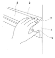
- FIGS. 2 to 4 show a state in which the user has grabbed the handrail according to the first embodiment.
- the user of the handrail grabs the handrail from various directions depending on the position of the body. Also, there are various ways of gripping depending on which part of the hand the handrail can be gripped strongly.
- the usage states shown in the figure are examples thereof.
- the thumb is applied to the third finger stop (9), and the forefinger, the middle finger, the ring finger, and the little finger are applied to the first finger stop (7).
- the thumb moves along the third guide portion (6) from the bottom to the top, stops at the third finger stop portion (9), and grips the entire handrail.
- the palm of the hand completely wraps the handrail along the second guide portion (5), and the index finger, the middle finger, the ring finger, and the little finger extend along the first flat portion (2). As a result, the handrail is firmly held using the entire hand.
- the tip of the thumb is applied to the first finger stop (7), and the tips of the index finger, the middle finger, the ring finger, and the little finger are applied to the third finger stop (9).
- the thumb extends so that the entire finger is along the first flat portion (2), and the index finger, the middle finger, the ring finger, and the little finger are moved to the first guide portion (4) and the second guide portion (5). It extends along and is not often used to hold the handrail. However, the handrail is firmly held using all five fingers.
- the second and third joints of the index finger are applied to the second finger stop portion (8), and the middle finger and the ring finger are applied to the third finger stop portion (9).
- the thumb extends so that the whole finger is along the first flat portion (2), and the base of the thumb of the palm extends so as to be along the first flat portion (2) and the first guide portion (4).
- the little fingers and the palms other than the base of the thumb are rarely used to hold the handrail.
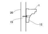
- the handrail (1) is firmly attached to the wall by the method shown in FIGS. In FIG. 5, it attaches with the attachment screw etc. (15) from both the inner side and the outer side (room side) of a wall.
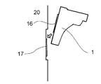
- the handrail is provided with an attachment hole (13) and attached from the outside of the wall with an attachment screw or the like (15). In FIG. 7, it is attached by a fitting tool.
- the lower end is attached to the wall (20), the upper end is a free end, and the attachment (17) is moved to a leaf spring in the direction of the wall, and the upper end is attached to the handrail (1) and the lower end is the free end in the handrail direction
- the fitting is composed of a fitting (16) that is biased in a leaf spring shape, and is attached by inserting the lower end of the fitting 16 from the upper end of the fitting 17 and fitting them together.
- the method of attaching to the wall is appropriately selected according to the strength and thickness of the wall or the material of the wall. According to the method shown in FIGS. 6 and 7, the handrail can be attached later after the room is completed.
- FIG. 8 Shows the six sides of the handrail with photos. 8 is the front surface, FIG. 9 is the back surface, FIG. 10 is the top surface, FIG. 11 is the bottom surface, FIG. 12 is the right side surface, and FIG.
- the handrail according to the present invention can be used by being attached to walls, corridors, stairs, etc. of elderly people or physically handicapped persons. In addition, because it is excellent in design and is not conscious of being a handrail, it can also be used for the residence of healthy people. It can be attached at the time of construction or renovation of the house, and can be retrofitted later.
- the handrail according to the present invention can be used in hospitals, elderly facilities, and the like.
Landscapes
- Engineering & Computer Science (AREA)
- Architecture (AREA)
- Civil Engineering (AREA)
- Structural Engineering (AREA)
- Steps, Ramps, And Handrails (AREA)
Abstract
容易に掴むことのできる手すりであって、手すりをつかみながら歩行する場合に、手指のスムーズな案内ができる手すりを提供することを課題とする。さらに健常者においても体調が不調な場合等に使用できる、一見して手すりとは見えないような、取り付け場所に馴染んだ形状の手すりを提供する事を課題とする。 頂面に、第一フラット部、前記第一フラット部と数mmの段差形状を介して連なる第二フラット部を有し、前記段差形状の部位が第一指止まり部を構成し、正面に、第一案内部、第二指止まり部、第二案内部、第三指止まり部及び第三案内部が順に連なっており、掴む際に手指が第一指止まり部、第二指止まり部又は第三指止まり部のいずれかにあてがわれるようにされている手すりによって課題を解決する。
Description
本発明は、壁、廊下、階段等に取り付ける手すりに関するものである。
従来より、高齢者等、歩行の困難な者等の移動を補助するために、壁、廊下、階段等に手すりを取り付けることが行われており、さまざまな形態の手すりが開発されている。
特許文献1には、手または肘先部分を滑らせつつ身体を支えることのできる、頂面がフラットにされた手すりが記載されている(図14)。しかし、図14の手すりは、手指で掴む場合を想定しておらず、手すりの使用者が、身体の位置や筋力に応じて様々な方向から手すりを掴んで歩行する場合の、指のスムーズな案内ができない。特許文献2には、手で掴む場合を想定した手すりが記載されているが(図15)、図15に示す手すりにおいても、手すりを掴みながら歩行する場合の、手指が安全でスムーズに案内ができるようにされていない。特許文献3、及び特許文献4に記載された手すりも同様である。
高齢者等、歩行の困難な障害者や、体調が不良な健常者は、手すりを掴むことも困難な場合が多いため、手すりは、容易に掴むことのできるものである必要がある。さらに、手すりを用いて歩行する際には、身体の動きに応じて手すりを掴み直し、掴む向きを変える必要があるため、手すりの形状が、指をスムーズに導くようにされていることが望ましいが、そのような手すりは、従来、見当たらなかった。
本発明は、容易に掴むことのできる手すりであって、手すりをつかみながら歩行する場合に、手指のスムーズな案内ができる手すりを提供することを課題とする。さらに健常者においても体調が不良な場合等に使用できる、一見して手すりとは見えないような、取り付け場所に馴染んだ形状の手すりを提供する事を課題とする。
頂面に、正面方向に延びる平坦な第一フラット部と、下方に1cm延びる第一指止まり部と、正面方向に延びる平坦な第二フラット部とが連続しており、正面に、前記第二フラット部と連続しており下方に延びる平坦な第一案内部と、背面方向に延びる平坦な第二指止まり部と、下方に円弧状に突出する第二案内部と、下方に背面方向に円弧状に突出して延びる第三案内部とが連続しており、前記第二案内部と前記第三案内部の境界が上方に延びる第三指止まり部を構成しており、掴まれる際に手指が第一指止まり部、第二指止まり部または第三指止まり部のいずれかにあてがわれるようにされている手すりによって課題を解決する。
すなわち、第一指止まり部は、平坦な第一フラット部と、これと平行に延びる第二フラット部との境界の高さ1cmの段差の部位である。
頂面に、正面方向に延びる平坦な第一フラット部と、下方に数mm延びる第一指止まり部と、正面方向に延びる平坦な第二フラット部とが連続しており、正面に、前記第二フラット部と連続しており下方に延びる平坦な第一案内部と、背面方向に延びる平坦な第二指止まり部と、下方に円弧状に突出する第二案内部と、下方に背面方向に円弧状に突出して延びる第三案内部とが連続しており、前記第二案内部と前記第三案内部の境界が上方に延びる第三指止まり部を構成しており、掴まれる際に手指が第一指止まり部、第二指止まり部または第三指止まり部のいずれかにあてがわれるようにされている手すりによって課題を解決する。
すなわち、この場合、第一指止まり部は、平坦な第一フラット部と、これと平行に延びる第二フラット部との境界の高さ数mmの段差の部位である。
手すりの素材は、木、金属、樹脂等、成形が可能なものであればなんでもよい。
また、頂面に、正面方向に延びる平坦な第一フラット部と、下方に1cm延びる第一指止まり部と、正面方向に延びる平坦な第二フラット部とが連続しており、正面に、前記第二フラット部と連続しており下方に延びる平坦な第一案内部と、背面方向に延びる平坦な第二指止まり部と、下方に円弧状に突出する第二案内部と、下方に背面方向に円弧状に突出して延びる第三案内部とが連続しており、前記第二案内部と前記第三案内部の境界が上方に延びる第三指止まり部を構成しており、掴まれる際に手指が第一指止まり部、第二指止まり部または第三指止まり部のいずれかにあてがわれるようにされている手すりであって、上端が手すりに取り付けてあり手すり方向に板バネ状に片寄せられる手すり側取付具の下端を下端が壁に取りつけてあり壁方向に板バネ状に片寄せられる壁側取付具の上端に挿入し、手すり側取付具と壁側取付具を互いに嵌め込むことによって壁に取り付けられた手すりによって課題を解決する。
このような嵌め具によって壁に取り付けることによって、手すりは壁に堅固に取り付けられる。
頂面の壁際の壁と並行する位置に、高さが数mmから1cm程度の第一指止まり部を設けることによって、手指のケガを避けることができる。例えば壁が細かい凹凸のある塗り壁の場合には、手すりを掴む際に手指が壁に擦れて怪我をする場合があるが、これを防ぐことができる。指止まり部の高さは5mm以下であることが望ましい。正面に、さらに、第二指止まり部及び第三指止まり部を設けることによって、手すりを様々な掴み方で容易に掴むことができる。これにより、掴む力の弱った者が容易に手すりを利用できる。また、いずれの角にも面取りを施し全体を曲線のみで構成するようにすることにより、手すりを掴み直す際に手指の案内や、手指を沿わせて移動する事がスムーズに行われ、かつ怪我をする事態を避けることができる。
手すりの形状が非常に美しく、手すりであることが判別できない外観であるため、これを施した場合であっても、手すりの施された住居であることを外観上判別できない。むしろ、この手すりを、住居に加えるデザインとして利用することができる。このような手すりの素材を、幅木等の住居の他の部分の素材と揃えることにより、デザイン的な効果をいっそう図ることができ、高齢者等、歩行の困難な障害者や、健常者であっても、体調が不良な場合等に、身体を支えたり移動の助けになる。
1 手すり
2 第一フラット部
3 第二フラット部
4 第一案内部
5 第二案内部
6 第三案内部
7 第一指止まり部
8 第二指止まり部
9 第三指止まり部
10 取付部
13 取付孔
15 取付ネジ
16 嵌め具
17 嵌め具
20 壁
2 第一フラット部
3 第二フラット部
4 第一案内部
5 第二案内部
6 第三案内部
7 第一指止まり部
8 第二指止まり部
9 第三指止まり部
10 取付部
13 取付孔
15 取付ネジ
16 嵌め具
17 嵌め具
20 壁
実施例1によって、最良の形態を示す。
図1から図7に、実施例1にかかる手すりを示す。本願では手すりを取り付けた際の天井方向を上方(又は頂面方向)、床方向を下方、手すりの使用者の側を正面、壁側を背面とする。
図1を参照して、実施例1にかかる手すりの形状を横断面で示す。手すり(1)は、頂面に、第一フラット部(2)及び第二フラット部(3)を有する。第一フラット部(2)と第二フラット部(3)の境界には第一指止まり部(7)が設けてある。さらに、手すり(1)は、正面に、第一案内部(4)、第二案内部(5)、及び第三案内部(6)を有し、第一案内部(4)と第二案内部(5)の境界には第二指止まり部(8)が設けてあり、第二案内部(5)と第三案内部(6)の境界には第三指止まり部(9)が設けてある。さらに、手すり(1)は、背面に、壁に取り付ける面となる取付部(10)を有する。
図2から図4に、実施例1にかかる手すりを使用者が掴んだ状態を示す。手すりの使用者は、身体の位置に応じてさまざまな方向から手すりを掴む。また、手のどの部分で手すりを強く握ることのできるかといったことに応じて様々な握り方になる。図に示した使用状態はそれらの例である。
図2では、親指が第三指止まり部(9)にあてがわれ、人さし指、なか指、薬指及び小指が第一指止まり部(7)にあてがわれている。使用者が手すりを掴み始める際、上方から手すりに接近する場合もあるが、使用者の姿勢により下方から手すりに接近する場合もある。下方から手すりに接近する際には、親指が第三案内部(6)の下方から上方に向けて沿って移動し、第三指止まり部(9)で止まり、手すり全体を掴む。てのひらは、第二案内部(5)に沿って手すりをすっぽり包むようになっており、人さし指、なか指、薬指及び小指は第一フラット部(2)に沿うように延びている。その結果、手すりは、手全体を使ってしっかりと握られる。
図3では、親指の先端が第一指止まり部(7)にあてがわれ、人さし指、なか指、薬指及び小指の先端が第三指止まり部(9)にあてがわれている。親指は指の全体が第一フラット部(2)に沿うように延びており、人さし指、なか指、薬指及び小指は指の全体が第一案内部(4)と第二案内部(5)に沿うように延びており、てのひらは手すりを握るためにあまり使用されない。しかし、五本指全体を使って手すりはしっかりと握られている。
図4では、人さし指の第二関節と第三関節が第二指止まり部(8)にあてがわれ、なか指、薬指が第三指止まり部(9)にあてがわれている。親指は指全体が第一フラット部(2)に沿うように延びており、てのひらのうち親指の根元辺りが第一フラット部(2)と第一案内部(4)に沿うように延びる。小指と、親指の根元辺り以外のてのひらは、手すりを握るためのあまり使用されない。
手すり(1)は、図5から図7に示すような方法で壁に堅固に取り付けられる。図5では壁の内側及び外側(部屋の側)の双方から取付ネジ等(15)で取り付けられている。図6では手すりに取付孔(13)を設け、壁の外側から取付ネジ等(15)で取り付けられている。図7では、嵌め具によって取り付けられる。下端が壁(20)に取りつけてあり上端が自由端で壁方向に板バネ状に片寄せられる取付具(17)と、上端が手すり(1)に取り付けてあり下端が自由端で手すり方向に板バネ状に片寄せられる取付具(16)とからなる嵌め具であって、取付具16の下端を取付具17の上端から挿入し互いに嵌め込むことによって取り付けられている。
壁に取り付ける方法は、壁の強度や厚み、または壁の素材に応じて、適宜選択する。図6及び図7に示す方法によれば、部屋が完成したのちに、手すりを後から取り付けることもできる。
手すりの一部の六面を写真で示す。図8が正面、図9が背面、図10が頂面、図11が底面、図12が右側面、図13が左側面である。
本発明にかかる手すりは、高齢者や身体の不自由な者等の、壁、廊下、階段等に取り付けて利用できる。また、デザイン的に優れており手すりであることが意識されないので健常者の住居にも利用できる。住居の施工時やリフォーム時に取り付けることもでき、その後に、別途、後付けすることもできる。
また、本発明にかかる手すりは、病院や、高齢者施設等でも利用できる。
Claims (4)
- 頂面に、正面方向に延びる平坦な第一フラット部と、下方に1cm延びる第一指止まり部と、正面方向に延びる平坦な第二フラット部とが連続しており、
正面に、前記第二フラット部と連続しており下方に延びる平坦な第一案内部と、背面方向に延びる平坦な第二指止まり部と、下方に円弧状に突出する第二案内部と、下方に背面方向に円弧状に突出して延びる第三案内部とが連続しており、前記第二案内部と前記第三案内部の境界が上方に延びる第三指止まり部を構成しており、掴まれる際に手指が第一指止まり部、第二指止まり部または第三指止まり部のいずれかにあてがわれるようにされている手すり。 - 頂面に、正面方向に延びる平坦な第一フラット部と、下方に数mm~1cm延びる第一指止まり部と、正面方向に延びる平坦な第二フラット部とが連続しており、正面に、前記第二フラット部と連続しており下方に延びる平坦な第一案内部と、背面方向に延びる平坦な第二指止まり部と、下方に円弧状に突出する第二案内部と、下方に背面方向に円弧状に突出して延びる第三案内部とが連続しており、前記第二案内部と前記第三案内部の境界が上方に延びる第三指止まり部を構成しており、掴まれる際に手指が第一指止まり部、第二指止まり部または第三指止まり部のいずれかにあてがわれるようにされている手すり。
- 請求項1または請求項2に記載の手すりであって、第三指止まり部以外の角が面取りされていることを特徴とする手すり。
- 頂面に、正面方向に延びる平坦な第一フラット部と、下方に1cm延びる第一指止まり部と、正面方向に延びる平坦な第二フラット部とが連続しており、
正面に、前記第二フラット部と連続しており下方に延びる平坦な第一案内部と、背面方向に延びる平坦な第二指止まり部と、下方に円弧状に突出する第二案内部と、下方に背面方向に円弧状に突出して延びる第三案内部とが連続しており、前記第二案内部と前記第三案内部の境界が上方に延びる第三指止まり部を構成しており、掴まれる際に手指が第一指止まり部、第二指止まり部または第三指止まり部の、いずれかにあてがわれるようにされている手すりであって、上端が手すりに取り付けてあり手すり方向に板バネ状に片寄せられる手すり側取付具の下端を下端が壁に取りつけてあり、壁方向に板バネ状に片寄せられる壁側取付具の上端に挿入し、手すり側取付具と壁側取付具を互いに嵌め込むことによって壁に取り付けられた手すり。
Priority Applications (3)
| Application Number | Priority Date | Filing Date | Title |
|---|---|---|---|
| US13/810,043 US9187906B2 (en) | 2010-07-12 | 2011-07-08 | Handrail |
| SG2013002696A SG187540A1 (en) | 2010-07-12 | 2011-07-08 | Handrail |
| EP11806705.7A EP2594702A4 (en) | 2010-07-12 | 2011-07-08 | Handrail |
Applications Claiming Priority (2)
| Application Number | Priority Date | Filing Date | Title |
|---|---|---|---|
| JP2010158238A JP4633861B1 (ja) | 2010-07-12 | 2010-07-12 | 手すり |
| JP2010-158238 | 2010-07-12 |
Publications (1)
| Publication Number | Publication Date |
|---|---|
| WO2012008375A1 true WO2012008375A1 (ja) | 2012-01-19 |
Family
ID=43768645
Family Applications (1)
| Application Number | Title | Priority Date | Filing Date |
|---|---|---|---|
| PCT/JP2011/065677 Ceased WO2012008375A1 (ja) | 2010-07-12 | 2011-07-08 | 手すり |
Country Status (6)
| Country | Link |
|---|---|
| US (1) | US9187906B2 (ja) |
| EP (1) | EP2594702A4 (ja) |
| JP (1) | JP4633861B1 (ja) |
| SG (1) | SG187540A1 (ja) |
| TW (1) | TW201211363A (ja) |
| WO (1) | WO2012008375A1 (ja) |
Cited By (1)
| Publication number | Priority date | Publication date | Assignee | Title |
|---|---|---|---|---|
| RU2645793C2 (ru) * | 2013-03-08 | 2018-02-28 | Сэн-Гобэн Гласс Франс | Электропроводящая основа для органического светодиода oled, содержащий ее oled и ее изготовление |
Families Citing this family (4)
| Publication number | Priority date | Publication date | Assignee | Title |
|---|---|---|---|---|
| ES2761173T3 (es) | 2009-05-15 | 2020-05-19 | Univ New York State Res Found | Análogos de curcumina como quelantes de zinc y sus usos |
| USD733324S1 (en) * | 2013-12-05 | 2015-06-30 | Inpro Corporation | Handrail |
| USD988541S1 (en) * | 2020-10-02 | 2023-06-06 | Daniel Cortavitarte Pérez | Draft excluder for doors and windows |
| EP4071056B1 (en) * | 2021-04-09 | 2024-07-31 | B/E Aerospace (UK) Limited | Bump strip |
Citations (7)
| Publication number | Priority date | Publication date | Assignee | Title |
|---|---|---|---|---|
| JPH0324458U (ja) * | 1989-07-17 | 1991-03-13 | ||
| JP2000220270A (ja) | 1999-01-29 | 2000-08-08 | Misawa Homes Co Ltd | 手 摺 |
| JP2000240250A (ja) | 1999-02-24 | 2000-09-05 | Kishimoto:Kk | カウンター等の手摺り構造 |
| JP2000274040A (ja) | 1999-03-26 | 2000-10-03 | Matsushita Electric Works Ltd | 手摺りの取付け構造 |
| JP2003301582A (ja) * | 2002-04-12 | 2003-10-24 | Anecom Japan Kk | 手 摺 |
| JP2004218327A (ja) | 2003-01-16 | 2004-08-05 | Kaidaa Baseboard Kogyo:Kk | フラット手すりとその取付け方法 |
| JP2005042345A (ja) * | 2003-07-25 | 2005-02-17 | Kaiken:Kk | 安全手摺 |
Family Cites Families (14)
| Publication number | Priority date | Publication date | Assignee | Title |
|---|---|---|---|---|
| US2886278A (en) * | 1956-10-08 | 1959-05-12 | Kenneth M Opie | Wall bracket |
| US3298147A (en) * | 1964-07-17 | 1967-01-17 | Haberman Painting & Decorating | Detachable building trim |
| US3991537A (en) * | 1973-08-20 | 1976-11-16 | Brown Russell L | Chair rail |
| USD345020S (en) * | 1992-05-21 | 1994-03-08 | Salvatore Audia | Decorative molding |
| JP3024458U (ja) | 1995-11-09 | 1996-05-21 | 日本住宅パネル工業協同組合 | 手 摺 |
| US5752356A (en) * | 1996-12-16 | 1998-05-19 | Miklavic; Thomas D. | Detachable wall trim |
| AU4005399A (en) * | 1998-05-21 | 1999-12-06 | Construction Specialties, Inc. | Handrail/leaning rail |
| JP3522565B2 (ja) * | 1999-02-23 | 2004-04-26 | 積水化学工業株式会社 | 手すり |
| JP2002115381A (ja) * | 2000-08-03 | 2002-04-19 | Sekisui Chem Co Ltd | 手すりおよび手すり本体 |
| US6425216B1 (en) * | 2001-03-20 | 2002-07-30 | Alabama Venetian Blind Company | #35 outside mount glass door mount |
| JP2004232321A (ja) * | 2003-01-30 | 2004-08-19 | Atlas:Kk | 手摺 |
| JP2004263409A (ja) * | 2003-02-28 | 2004-09-24 | Toto Ltd | 手すり |
| USD510631S1 (en) * | 2004-07-08 | 2005-10-11 | Ching Feng Blinds Ind. Co., Ltd. | Frame of window/door shutter (II) |
| USD674122S1 (en) * | 2011-09-15 | 2013-01-08 | Azek Building Products, Inc. | Crosshead pediment |
-
2010
- 2010-07-12 JP JP2010158238A patent/JP4633861B1/ja not_active Expired - Fee Related
-
2011
- 2011-07-08 US US13/810,043 patent/US9187906B2/en not_active Expired - Fee Related
- 2011-07-08 EP EP11806705.7A patent/EP2594702A4/en not_active Withdrawn
- 2011-07-08 WO PCT/JP2011/065677 patent/WO2012008375A1/ja not_active Ceased
- 2011-07-08 TW TW100124348A patent/TW201211363A/zh unknown
- 2011-07-08 SG SG2013002696A patent/SG187540A1/en unknown
Patent Citations (7)
| Publication number | Priority date | Publication date | Assignee | Title |
|---|---|---|---|---|
| JPH0324458U (ja) * | 1989-07-17 | 1991-03-13 | ||
| JP2000220270A (ja) | 1999-01-29 | 2000-08-08 | Misawa Homes Co Ltd | 手 摺 |
| JP2000240250A (ja) | 1999-02-24 | 2000-09-05 | Kishimoto:Kk | カウンター等の手摺り構造 |
| JP2000274040A (ja) | 1999-03-26 | 2000-10-03 | Matsushita Electric Works Ltd | 手摺りの取付け構造 |
| JP2003301582A (ja) * | 2002-04-12 | 2003-10-24 | Anecom Japan Kk | 手 摺 |
| JP2004218327A (ja) | 2003-01-16 | 2004-08-05 | Kaidaa Baseboard Kogyo:Kk | フラット手すりとその取付け方法 |
| JP2005042345A (ja) * | 2003-07-25 | 2005-02-17 | Kaiken:Kk | 安全手摺 |
Non-Patent Citations (1)
| Title |
|---|
| See also references of EP2594702A4 * |
Cited By (1)
| Publication number | Priority date | Publication date | Assignee | Title |
|---|---|---|---|---|
| RU2645793C2 (ru) * | 2013-03-08 | 2018-02-28 | Сэн-Гобэн Гласс Франс | Электропроводящая основа для органического светодиода oled, содержащий ее oled и ее изготовление |
Also Published As
| Publication number | Publication date |
|---|---|
| EP2594702A1 (en) | 2013-05-22 |
| US20130112932A1 (en) | 2013-05-09 |
| SG187540A1 (en) | 2013-03-28 |
| JP2012021283A (ja) | 2012-02-02 |
| JP4633861B1 (ja) | 2011-02-16 |
| TW201211363A (en) | 2012-03-16 |
| US9187906B2 (en) | 2015-11-17 |
| EP2594702A4 (en) | 2017-08-16 |
Similar Documents
| Publication | Publication Date | Title |
|---|---|---|
| JP4633861B1 (ja) | 手すり | |
| US6857622B2 (en) | Ergonomic handrail | |
| JP6162550B2 (ja) | 木質系手摺の取付構造および取付方法 | |
| JP3678207B2 (ja) | 手摺 | |
| WO2023052787A1 (en) | Hand rail system, lever-operated sleeve mechanism, and modular hand rail and grip system | |
| JP5186350B2 (ja) | 手摺り及び手摺りの接続構造 | |
| HK1185643A (en) | Handrail | |
| JP3979593B2 (ja) | フラット手すりとその取付け方法 | |
| JP2008280164A (ja) | エレベータのかご内手摺装置 | |
| JP2010138665A (ja) | 手すり | |
| JP2010053581A (ja) | 手摺りの補助保持具 | |
| JP4056640B2 (ja) | 手摺装置 | |
| JP5150221B2 (ja) | 手摺構造及び手摺構造の取り付け方法 | |
| JP2005042345A (ja) | 安全手摺 | |
| JP2004263409A (ja) | 手すり | |
| JP3126020U (ja) | 螺旋型手すり | |
| JP3001698U (ja) | 手 摺 | |
| JP4688412B2 (ja) | 台形型手すり | |
| JP2018184704A (ja) | 階段手摺及び階段室 | |
| JP3197926U (ja) | グリップハンドル型階段手摺 | |
| JP2012046890A (ja) | 手摺 | |
| JP3049750U (ja) | 滑り止め付き手摺り | |
| CA2360861C (en) | Ergonomic handrail | |
| JP2005133523A (ja) | 手すり | |
| HK1101851A2 (en) | Handrail and installation structure of handrail |
Legal Events
| Date | Code | Title | Description |
|---|---|---|---|
| 121 | Ep: the epo has been informed by wipo that ep was designated in this application |
Ref document number: 11806705 Country of ref document: EP Kind code of ref document: A1 |
|
| NENP | Non-entry into the national phase |
Ref country code: DE |
|
| WWE | Wipo information: entry into national phase |
Ref document number: 13810043 Country of ref document: US |
|
| WWE | Wipo information: entry into national phase |
Ref document number: 2011806705 Country of ref document: EP |