WO2012010532A2 - Verfahren und vorrichtung zur sensorlosen lageerkennung einer elektronisch kommutierten elektrischen maschine - Google Patents
Verfahren und vorrichtung zur sensorlosen lageerkennung einer elektronisch kommutierten elektrischen maschine Download PDFInfo
- Publication number
- WO2012010532A2 WO2012010532A2 PCT/EP2011/062190 EP2011062190W WO2012010532A2 WO 2012010532 A2 WO2012010532 A2 WO 2012010532A2 EP 2011062190 W EP2011062190 W EP 2011062190W WO 2012010532 A2 WO2012010532 A2 WO 2012010532A2
- Authority
- WO
- WIPO (PCT)
- Prior art keywords
- phase
- voltages
- induced
- voltage
- electric machine
- Prior art date
- Legal status (The legal status is an assumption and is not a legal conclusion. Google has not performed a legal analysis and makes no representation as to the accuracy of the status listed.)
- Ceased
Links
Classifications
-
- G—PHYSICS
- G01—MEASURING; TESTING
- G01B—MEASURING LENGTH, THICKNESS OR SIMILAR LINEAR DIMENSIONS; MEASURING ANGLES; MEASURING AREAS; MEASURING IRREGULARITIES OF SURFACES OR CONTOURS
- G01B7/00—Measuring arrangements characterised by the use of electric or magnetic techniques
- G01B7/30—Measuring arrangements characterised by the use of electric or magnetic techniques for measuring angles or tapers; for testing the alignment of axes
-
- H—ELECTRICITY
- H02—GENERATION; CONVERSION OR DISTRIBUTION OF ELECTRIC POWER
- H02P—CONTROL OR REGULATION OF ELECTRIC MOTORS, ELECTRIC GENERATORS OR DYNAMO-ELECTRIC CONVERTERS; CONTROLLING TRANSFORMERS, REACTORS OR CHOKE COILS
- H02P6/00—Arrangements for controlling synchronous motors or other dynamo-electric motors using electronic commutation dependent on the rotor position; Electronic commutators therefor
- H02P6/14—Electronic commutators
- H02P6/16—Circuit arrangements for detecting position
- H02P6/18—Circuit arrangements for detecting position without separate position detecting elements
- H02P6/182—Circuit arrangements for detecting position without separate position detecting elements using back-emf in windings
-
- H—ELECTRICITY
- H02—GENERATION; CONVERSION OR DISTRIBUTION OF ELECTRIC POWER
- H02P—CONTROL OR REGULATION OF ELECTRIC MOTORS, ELECTRIC GENERATORS OR DYNAMO-ELECTRIC CONVERTERS; CONTROLLING TRANSFORMERS, REACTORS OR CHOKE COILS
- H02P21/00—Arrangements or methods for the control of electric machines by vector control, e.g. by control of field orientation
- H02P21/14—Estimation or adaptation of machine parameters, e.g. flux, current or voltage
- H02P21/18—Estimation of position or speed
Definitions
- the present invention relates to electronically commutated electrical machines, in particular to methods for sensorless position detection of a rotor of an electrical machine.
- the rotor position is detected by an integrated or separate position sensor and provided to the control unit, which performs the electronic commutation.
- the rotor position is determined sensorless from the motor voltages and / or motor currents.
- a known method for sensorless position detection is the so-called back-EM F method, in which a rotor position is derived from a profile of the induced voltage in a phase strand of the electrical machine. Since it is necessary to measure the induced voltage, the corresponding
- a rotor position determination using the Back-EM F method is generally possible exactly in such electrical machines, in which the induced voltage describes a sinusoidal profile and the phase voltages are not provided by an inverter, since there is a phase connection is not de-energized can be.
- An example for the noise behavior advantageous permanent voltage specification (without blanking interval) is not possible with a back-EMF method.
- the quality of known methods for sensorless operation of sinusoidal machines, such as in a sensorless field-oriented control decreases, the more the course of the induced voltage deviates from a sinusoidal profile. It is therefore an object of the present invention to provide an improved method for the sensorless detection of the rotor position available, which can also be used when the induced voltages are not sinusoidal and which can be used regardless of the Kommutêtsart. Disclosure of the invention
- a method for determining a rotor position of a rotary, multi-phase, electronically commutated electric machine is provided.
- the electric machine has a plurality of phase windings, which can be energized via phase connections.
- the method comprises the following steps:
- One idea of the above method is to determine the induced voltage in the phase windings in a multi-phase electric machine and to provide it as a voltage vector of a fixed-stator coordinate system, so that the space vector angle of the induced voltage is an indication of the rotor position or can be assigned directly. This allows a particularly simple derivation of the rotor position from the induced voltage.
- the provision of the voltage vector of the induced voltage determined by the induced voltages with respect to the stator-fixed Cartesian coordinate system can be performed by converting the detected induced voltages into the stator-fixed Cartesian coordinate system or by applying the determined phase voltages and phase currents to the phase terminals of the electric machine stator-fixed Cartesian coordinate system can be converted before the induced voltages are determined from these.
- the converted voltage vector of the induced voltage can be subjected to a correction angle, the correction angle depending on the voltage vector angle.
- the correction angle is used to correct the error of a non-sinusoidal induced voltage in the rotor position determination.
- the correction angle may be determined using the voltage vector angle and / or the rotor speed.
- the correction angle can be determined using a lookup table by specifying the voltage vector angle and / or the speed.
- the determination of the phase voltages and phase currents at the phase terminals of the electrical machine can be carried out by measuring the phase voltages and phase currents or by determining the phase voltages from a DC link voltage provided and a pulse width modulation duty cycle with which the phase connections are driven. be determined.
- an apparatus for determining a rotor position of a rotary, multi-phase, electronically commutated electric machine is provided.
- the electric machine has a plurality of phase windings, which can be energized via phase connections.
- the device comprises
- control unit configured to
- an engine system is provided with a rotary multi-phase electronically commutated electric machine and the above apparatus.
- a computer program product which contains a program code which, when used on a data processing is carried out in the method according to one of claims 1 to 4, the following steps:
- FIG. 1a shows a schematic representation of a synchronous machine as an example of an electronically commutated electrical machine
- Figure 1 b is an auxiliary representation to illustrate a conversion of the voltage vector of the induced voltage into a fixed-stator Cartesian coordinate system
- FIG. 2 shows a flowchart for illustrating the method for determining the rotor position from the induced
- FIG. 1 shows a simplified illustration of a three-phase electronically commutated electric machine 1 as an internal rotor machine. you detects a stator 2 with three staggered by 120 ° to each other stator teeth 3.
- the number of stator teeth 3 on the stator 2 is usually larger and corresponds for example to a multiple of three, such. For example, nine, twelve or eighteen.
- the stator teeth 3 are each provided with a phase winding 4 and provide a component of the stator magnetic field when energized accordingly.
- the stator windings 4 are connected in a conventional manner in delta connection or in star connection with each other. Each of the stator windings 4 can be energized via a corresponding phase connection (not shown) of the electric machine 1.
- a rotor 5 is rotatably mounted as a rotor of the electric machine 1, which in the simplified representation of Figure 1a has two rotor poles 6, which are arranged opposite to each other.
- synchronous machines may have more than two rotor poles, for example four or eight rotor poles.
- control unit 10 is provided, the z. B. by means of a driver circuit 1 1, the stator windings 4 drives.
- the control takes place by means of an electronic commutation, so that each of the phase windings 4 is acted upon by a phase voltage depending on the position of the rotor 5.
- Various types of commutation can be provided by the control unit 10, such as block commutation or trapezoidal commutation and the like.
- a specific phase voltage can be generated by a pulse width modulation of an applied intermediate circuit voltage or supply voltage.
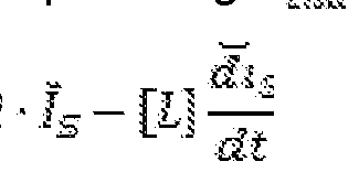
- the induced voltage can also be determined by determining the phase voltages% and the phase currents an at the phase terminals.
- the phase voltages t / s and the phase currents T s can be determined, for example, by measurement.
- the measurement of the phase voltages S and the phase currents S is performed by suitable measuring devices 12, which may be provided either in the driver circuit 11 or in the control unit 10.
- the measuring devices 12 may include, for example, shunts, analog-to-digital converters, and the like.
- the phase voltages ⁇ and the phase currents i s can be determined from a measurement or knowledge of an intermediate circuit voltage (supply voltage) applied to the driver circuit 11 and the pulse width modulation duty cycle with which the relevant phase winding is driven.
- the induced voltage ü i ä as rotating voltage vector of a statorfesten coordinate system, in particular a Cartesian coordinate system represent.
- Figure 1 b wherein as a replacement image of the stator 2 has two mutually offset by 90 ° stator windings 4.
- the stator windings 4 in a multi-phase electric machine can always be displayed in a statorfesten coordinate system , ie on an electric machine with staggered by 90 ° stator windings.
- the induced voltage of the stator-fixed Cartesian coordinate system in polar representation can be determined as follows:
- the induced voltage u i ⁇ aä has a sinusoidal course.
- the induced voltage / / ⁇ ! ⁇ depends to a considerable extent on the design of the electric machine, in particular on the shaping of the air gap between the rotor poles 6 and the stator teeth 3.
- a non-sinusoidal induced voltage to be performed a correction for this purpose, for example, a dependent of the space vector angle correction angle ⁇ ( ⁇ ) are provided, with the space vector angle of the non-sinusoidal induced voltage ü ⁇ ä is applied to correct this to the rotor position.
- the result of the correction is that the space vector angle ⁇ of the non-sinusoidal voltage is also subjected to the correction angle ⁇ ( ⁇ ) in a position-dependent manner.
- the rotational speed n of the electrical machine can be taken into account, since the induced voltage, in particular its course, is likewise dependent on the rotational speed n.
- the provision of the correction angle ⁇ ( ⁇ , ⁇ ) is generally carried out by a look-up table, which is either engine-individually learned after the manufacture of the electric machine 1 or dependent on the engine type.
- the filter, the U in d results, for example, from the type of measurement (eg, digital sampling) and determination of U in d- By the derivative of the phase current to dt, for example, by the finite dt a
- the learning can be done, for example, by the phase potentials for certain rotor positions ⁇ 'and speeds n in the currentless case, ie not applied phase voltages, and thus a profile of the induced voltage u insi depending on the rotor position ⁇ ' and the rotational speed n can be detected.
- the correction angle ⁇ ( ⁇ , n) results from the difference between the rotor position (' me ss and the space vector angle of the induced voltage 5 m8äS5 determined at a certain rotor position (p' meS s and a certain speed n meas -
- FIG. 2 shows a flow chart for illustrating the method for determining the rotor position of an electrical machine 1.
- step S1 first the induced voltages at the phase terminals, via which the phase windings 4 are energized, are determined.
- the applied phase voltages and the corresponding phase currents are detected and the induced voltages are determined according to the above formula. From this, the induced voltage at the corresponding phase connection is determined.
- step S2 the thus determined induced voltages for each phase are converted into a stator-fixed Cartesian coordinate system and one obtains an amount of the induced voltage and a space vector angle for the current rotor position.
- step S3 the space vector angle ⁇ is the induced voltage u ia . ⁇ ä e ⁇ ⁇ * by the corresponding correction angle ⁇ ( ⁇ , n) is applied (added), which is determined from a lookup table or according to a predetermined function.
- the corrected space vector angle ⁇ ' ⁇ ' ⁇ + ⁇ ( ⁇ , ⁇ ) is calculated in step S4.
Landscapes
- Engineering & Computer Science (AREA)
- Power Engineering (AREA)
- Physics & Mathematics (AREA)
- General Physics & Mathematics (AREA)
- Control Of Motors That Do Not Use Commutators (AREA)
- Control Of Ac Motors In General (AREA)
Abstract
Description
Claims
Priority Applications (4)
| Application Number | Priority Date | Filing Date | Title |
|---|---|---|---|
| JP2013520092A JP2013532936A (ja) | 2010-07-22 | 2011-07-18 | 電子整流電動機を、センサを用いずに位置識別する方法および装置 |
| EP11739025.2A EP2596579B1 (de) | 2010-07-22 | 2011-07-18 | Verfahren und vorrichtung zur sensorlosen lageerkennung einer elektronisch kommutierten elektrischen maschine |
| CN201180035855.2A CN103109454B (zh) | 2010-07-22 | 2011-07-18 | 用于在无传感器的情况下对电子换向的电机进行位置识别的方法和装置 |
| US13/811,406 US10101146B2 (en) | 2010-07-22 | 2011-07-18 | Method and device for the sensor-free position determination of an electronically commutated electric machine |
Applications Claiming Priority (2)
| Application Number | Priority Date | Filing Date | Title |
|---|---|---|---|
| DE102010038295.7 | 2010-07-22 | ||
| DE102010038295A DE102010038295A1 (de) | 2010-07-22 | 2010-07-22 | Verfahren und Vorrichtung zur sensorlosen Lageerkennung einer elektronisch kommutierten elektrischen Maschine |
Publications (2)
| Publication Number | Publication Date |
|---|---|
| WO2012010532A2 true WO2012010532A2 (de) | 2012-01-26 |
| WO2012010532A3 WO2012010532A3 (de) | 2013-01-10 |
Family
ID=44629545
Family Applications (1)
| Application Number | Title | Priority Date | Filing Date |
|---|---|---|---|
| PCT/EP2011/062190 Ceased WO2012010532A2 (de) | 2010-07-22 | 2011-07-18 | Verfahren und vorrichtung zur sensorlosen lageerkennung einer elektronisch kommutierten elektrischen maschine |
Country Status (6)
| Country | Link |
|---|---|
| US (1) | US10101146B2 (de) |
| EP (1) | EP2596579B1 (de) |
| JP (1) | JP2013532936A (de) |
| CN (1) | CN103109454B (de) |
| DE (1) | DE102010038295A1 (de) |
| WO (1) | WO2012010532A2 (de) |
Families Citing this family (3)
| Publication number | Priority date | Publication date | Assignee | Title |
|---|---|---|---|---|
| US9425725B2 (en) * | 2013-02-28 | 2016-08-23 | Cirrus Logic, Inc. | Position estimation system and method for an electric motor |
| DE102013212876A1 (de) * | 2013-07-02 | 2015-01-08 | Robert Bosch Gmbh | Verfahren und Vorrichtung zur sensorlosen Ermittlungeiner Läuferlage einer elektrischen Maschine |
| DE102014212554A1 (de) * | 2014-06-30 | 2015-12-31 | Siemens Aktiengesellschaft | Diagnose eines Antriebssystems sowie Antriebssystem |
Family Cites Families (18)
| Publication number | Priority date | Publication date | Assignee | Title |
|---|---|---|---|---|
| FI885272A7 (fi) * | 1988-01-29 | 1989-07-30 | Siemens Ag | Foerfarande foer bildande av lastvinkel-nuvaerdet foer en faeltorienterad reglerad vridfaeltmaskin och motsvarande regleringsanordning. |
| US5471122A (en) * | 1993-09-14 | 1995-11-28 | Allegro Microsystems, Inc. | DC-motor bridge driver with end-of-braking detector |
| JP2000152687A (ja) | 1998-11-05 | 2000-05-30 | Daikin Ind Ltd | ブラシレスdcモータ制御方法およびその装置 |
| EP1219015A4 (de) * | 1999-09-17 | 2006-05-10 | Delphi Tech Inc | Permament magnet motor regler mit geringer welligkeit |
| JP3411878B2 (ja) * | 2000-03-06 | 2003-06-03 | 株式会社日立製作所 | 同期モータの回転子位置推定方法、位置センサレス制御方法及び制御装置 |
| JP3840082B2 (ja) * | 2000-10-11 | 2006-11-01 | 松下電器産業株式会社 | 位置センサレスモータ制御方法及び制御装置 |
| JP4737858B2 (ja) * | 2001-03-27 | 2011-08-03 | 東芝エレベータ株式会社 | 永久磁石電動機の制御装置 |
| CN1254908C (zh) * | 2001-12-18 | 2006-05-03 | 乐金电子(天津)电器有限公司 | 同步磁阻电机的无传感控制方法 |
| EP1383231B1 (de) * | 2002-07-18 | 2017-03-01 | Grundfos A/S | Verfahren zum Erfassen des magnetischen Flusses der Rotorposition und/oder der Drehzahl |
| JP4395313B2 (ja) * | 2003-04-04 | 2010-01-06 | 日本精工株式会社 | モータ駆動制御装置および電動パワーステアリング装置 |
| JP4665735B2 (ja) * | 2005-11-30 | 2011-04-06 | 株式会社日立製作所 | 同期モータの駆動システム及び同期モータの駆動方法 |
| JP5170505B2 (ja) * | 2007-02-07 | 2013-03-27 | 株式会社ジェイテクト | モータ制御装置 |
| JP5435252B2 (ja) * | 2008-01-30 | 2014-03-05 | 株式会社ジェイテクト | 車両用操舵装置 |
| JP5267848B2 (ja) * | 2008-04-15 | 2013-08-21 | 株式会社ジェイテクト | モータ制御装置 |
| JP5159465B2 (ja) * | 2008-06-24 | 2013-03-06 | 株式会社東芝 | モータ制御装置および半導体集積回路装置 |
| JP2010029028A (ja) * | 2008-07-23 | 2010-02-04 | Jtekt Corp | モータ制御装置 |
| JP5305796B2 (ja) * | 2008-09-09 | 2013-10-02 | 株式会社東芝 | モータ制御装置,モータ駆動システム,ポンプ装置並びにモータ制御方法 |
| US8242721B2 (en) * | 2008-10-31 | 2012-08-14 | R&D Dynamics Corporation | Position-sensorless control system and method of operation for a synchronous motor |
-
2010
- 2010-07-22 DE DE102010038295A patent/DE102010038295A1/de not_active Withdrawn
-
2011
- 2011-07-18 CN CN201180035855.2A patent/CN103109454B/zh active Active
- 2011-07-18 WO PCT/EP2011/062190 patent/WO2012010532A2/de not_active Ceased
- 2011-07-18 EP EP11739025.2A patent/EP2596579B1/de active Active
- 2011-07-18 JP JP2013520092A patent/JP2013532936A/ja active Pending
- 2011-07-18 US US13/811,406 patent/US10101146B2/en active Active
Non-Patent Citations (1)
| Title |
|---|
| None |
Also Published As
| Publication number | Publication date |
|---|---|
| CN103109454B (zh) | 2016-07-06 |
| EP2596579B1 (de) | 2014-12-03 |
| CN103109454A (zh) | 2013-05-15 |
| WO2012010532A3 (de) | 2013-01-10 |
| US10101146B2 (en) | 2018-10-16 |
| DE102010038295A1 (de) | 2012-01-26 |
| JP2013532936A (ja) | 2013-08-19 |
| US20130207647A1 (en) | 2013-08-15 |
| EP2596579A2 (de) | 2013-05-29 |
Similar Documents
| Publication | Publication Date | Title |
|---|---|---|
| DE102013209562B4 (de) | Verfahren, Systeme und Geräte für das Schätzen elektrischer Winkelposition und/oder Winkelgeschwindigkeit eines Rotors einer elektrischen Maschine | |
| DE102014212554A1 (de) | Diagnose eines Antriebssystems sowie Antriebssystem | |
| EP1969714A1 (de) | Verfahren zum bestimmen der magnettemperatur bei synchronmaschinen | |
| EP2309282B1 (de) | Verfahren zur Fehlererkennung bei der Ansteuerung eines Drehfeldmotors | |
| DE102010001427A1 (de) | Sensoreinheit zur Befestigung an einer elektrischen Maschine sowie Motorsystem | |
| EP2619899B1 (de) | Verfahren und vorrichtung zur sensorlosen ermittlung einer läuferlage einer elektrischen maschine | |
| EP2596579B1 (de) | Verfahren und vorrichtung zur sensorlosen lageerkennung einer elektronisch kommutierten elektrischen maschine | |
| EP3017536B1 (de) | Verfahren und vorrichtung zur sensorlosen ermittlung einer läuferlage einer elektrischen maschine | |
| DE102007063386B4 (de) | Verfahren zur Bestimmung von elektrischen Rotorpositionen in elektrischen Maschinen mit Vorrichtungen zur Kommutierung und Positionserkennung | |
| WO2018072778A1 (de) | Verfahren zur korrektur von messabweichungen eines sinus-cosinus-rotationssensors | |
| DE112017001330T5 (de) | Motorsteuerungsvorrichtung | |
| EP1734648A1 (de) | Asymmetrische Ansteuerung eines sensorlosen und bürstenlosen Elektromotors | |
| WO2007090760A2 (de) | Verfahren und vorrichtung zum bestimmen des drehmoments einer elektrischen maschine | |
| EP3556011B1 (de) | Verfahren zur bestimmung der winkellage des rotors eines von einem wechselrichter gespeisten synchronmotors und eine vorrichtung zur durchführung des verfahrens | |
| EP4037180A1 (de) | Verfahren zum ansteuern eines mindestens zweiphasigen bürstenlosen motors | |
| DE102012012762A1 (de) | Einrichtung und Verfahren zur Bestimmung von Positionen eines Rotors in elektrischen Maschinen | |
| DE102010040223A1 (de) | Verfahren zum Betrieb einer Drehfeldmaschine | |
| EP3319222B1 (de) | Steuerungsverfahren für einen elektromotor, steuergerät sowie elektromotor | |
| DE102008011164B4 (de) | Verfahren und Vorrichtung zur dynamischen Kompensation der Nullpunktabweichung bei der Wicklungsstromerfassung für die Steuerung eines bürstenlosen Motors | |
| DE102013201241A1 (de) | Verfahren und Einrichtung zur Bestimmung der Position des Rotors bei einem bürstenlosen Gleichstrommotor | |
| EP2594017B1 (de) | Verfahren und vorrichtung zur bestimmung eines momentanen drehmoments einer elektronisch kommutierten elektrischen maschine sowie zur regelung des mittleren drehmoments | |
| WO2019084584A1 (de) | Verfahren zur Ermittlung der Rotorposition von synchron laufenden elektrischen Maschinen ohne mechanischen Geber | |
| DE102008041549A1 (de) | Verfahren zur Erfassung der Rotorlage einer elektrischen Maschine und Vorrichtung hierzu | |
| DE102014221406A1 (de) | Verfahren zum Ermitteln eines mechanischen Drehwinkels eines Rotors aufgrund eines elektrischen Drehwinkels | |
| EP4550656A1 (de) | Verfahren zum zweiphasigen betrieb eines dreiphasigen permanenterregten synchronmotors |
Legal Events
| Date | Code | Title | Description |
|---|---|---|---|
| WWE | Wipo information: entry into national phase |
Ref document number: 201180035855.2 Country of ref document: CN |
|
| WWE | Wipo information: entry into national phase |
Ref document number: 2011739025 Country of ref document: EP |
|
| ENP | Entry into the national phase |
Ref document number: 2013520092 Country of ref document: JP Kind code of ref document: A |
|
| 121 | Ep: the epo has been informed by wipo that ep was designated in this application |
Ref document number: 11739025 Country of ref document: EP Kind code of ref document: A2 |
|
| WWE | Wipo information: entry into national phase |
Ref document number: 13811406 Country of ref document: US |