WO2012014419A1 - 発情検知装置および発情検知システム - Google Patents
発情検知装置および発情検知システム Download PDFInfo
- Publication number
- WO2012014419A1 WO2012014419A1 PCT/JP2011/004138 JP2011004138W WO2012014419A1 WO 2012014419 A1 WO2012014419 A1 WO 2012014419A1 JP 2011004138 W JP2011004138 W JP 2011004138W WO 2012014419 A1 WO2012014419 A1 WO 2012014419A1
- Authority
- WO
- WIPO (PCT)
- Prior art keywords
- estrus
- state
- case
- livestock
- activity
- Prior art date
- Legal status (The legal status is an assumption and is not a legal conclusion. Google has not performed a legal analysis and makes no representation as to the accuracy of the status listed.)
- Ceased
Links
Images





Classifications
-
- A—HUMAN NECESSITIES
- A01—AGRICULTURE; FORESTRY; ANIMAL HUSBANDRY; HUNTING; TRAPPING; FISHING
- A01K—ANIMAL HUSBANDRY; AVICULTURE; APICULTURE; PISCICULTURE; FISHING; REARING OR BREEDING ANIMALS, NOT OTHERWISE PROVIDED FOR; NEW BREEDS OF ANIMALS
- A01K29/00—Other apparatus for animal husbandry
- A01K29/005—Monitoring or measuring activity
-
- A—HUMAN NECESSITIES
- A61—MEDICAL OR VETERINARY SCIENCE; HYGIENE
- A61D—VETERINARY INSTRUMENTS, IMPLEMENTS, TOOLS, OR METHODS
- A61D17/00—Devices for indicating trouble during labour of animals ; Methods or instruments for detecting pregnancy-related states of animals
- A61D17/002—Devices for indicating trouble during labour of animals ; Methods or instruments for detecting pregnancy-related states of animals for detecting period of heat of animals, i.e. for detecting oestrus
Definitions
- the present invention relates to an apparatus for detecting the estrus of livestock, particularly cattle.
- Target cows are equipped with pedometers.
- a day is divided into a plurality of time zones.
- This detection device extracts the number of steps counted by the pedometer for each time zone.
- This detection apparatus compares the counted number of steps with the number of steps in the same time zone in the past n days. The estrus state is detected based on the comparison result.
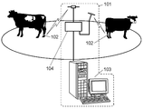
- This estrus state detection device includes a counting device 101 and at least one pedometer 102.
- the aggregation device 101 includes a computer 103 and a communication device 104.
- the pedometer 102 is attached to a cow's body, for example, a leg, a neck or the like, with a belt or the like.
- the pedometer 102 includes a walking determination unit, a communication unit, and a control unit.
- the step number determination unit counts the number of steps of the cow.
- the counted number of steps is sent from the step number determination unit to the control unit.
- the control unit accumulates the number of steps up to a predetermined time.
- the control unit sends the integrated value and a signal for identifying the solid to the communication unit.
- the communication unit transmits the received integrated value and a signal for identifying the individual to the communication device 104.
- the control unit sets the accumulated value to zero.
- the computer 103 stores step count data relating to the number of steps in the past, that is, D 1 , D 2 , D 3 , D 4 ,.
- the computer 103 compares the latest step count received via the communication device 104 with the past step count data. As a result of the comparison, when the latest number of steps tends to be larger than the past number of steps data, the computer 103 determines that the state is an estrus state.
- the conventional detection device requires a large-scale system including the counting device 101 in order to determine the estrus state of the cow.
- the equipment becomes expensive.
- the present invention detects an estrus state with a simple device.
- the estrus detection apparatus of the present invention includes a case attached to a livestock, an activity amount sensor that is housed in the case and detects the movement of the livestock, and an activity amount that is housed in the case and outputs from the activity amount sensor.
- An estrus determination unit that determines whether or not, and a display unit that is housed in the case and displays the estrus state when the estrus determination unit determines that the state is in the estrus state.
- Estrus detection devices are attached to livestock such as cows that are close to estrus. Only this estrus detection device can detect the estrus state of livestock. That is, the estrus state of livestock is detected without using a large-scale system.
- the estrus detection device is brought into an initial state by utilizing the characteristics of the 3-axis acceleration sensor.
- the estrus detection device can be operated without opening the case.
- the estrus device is kept sealed.
- FIG. 1A is an external front view of the estrus detection apparatus according to the first embodiment of the present invention.
- FIG. 1B is an external side view of the estrus detection apparatus according to the first embodiment of the present invention.
- FIG. 2 is an explanatory diagram showing a state in which the estrus detection apparatus according to the first embodiment of the present invention is attached to livestock.
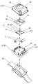
- FIG. 3 is an assembled perspective view of the estrus detection apparatus according to the first embodiment of the present invention.
- FIG. 4 is a conceptual front view showing the main part of the estrus detection apparatus according to the first embodiment of the present invention.
- FIG. 5 is a conceptual side view showing the main part of the estrus detection apparatus according to the first embodiment of the present invention.
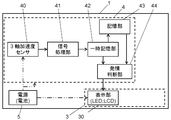
- FIG. 6 is a block diagram of the estrus detection apparatus according to the first embodiment of this invention.
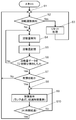
- FIG. 7 is a flowchart showing the operation of the estrus detection apparatus according to the first embodiment of this invention.
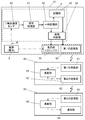
- FIG. 8 is a block diagram of an estrus detection system according to the second embodiment of this invention.
- FIG. 9 is a schematic view of a conventional estrus detection device.
- FIG. 1A and 1B are external views showing the estrus detection apparatus according to the first embodiment.
- the estrus detection device 1 has a belt 20 below the case 2.
- the case 2 is attached to the neck of a cow that is a domestic animal using a belt 20.
- the livestock to which the estrus detection device 1 is attached may be pigs or cows.
- the display substrate 3 includes a display unit 30.
- the control board 4 includes a three-axis acceleration sensor 40 that is an activity amount sensor, a signal processing unit 41, a temporary storage unit 42, a storage unit 43, and an estrus determination unit 44.
- the activity sensor detects the movement of livestock.
- Various acceleration sensors can be used as the activity amount sensor.
- the three-axis acceleration sensor 40 is used, the magnitude of the movement of the livestock and the direction of the movement can be detected in three dimensions, so that the movement of the livestock can be accurately detected.
- the triaxial acceleration sensor 40 is located at the center of gravity of the case 2. 3 and 5, the barycentric position is indicated by a one-dot chain line.
- the signal processing unit 41 converts the output from the triaxial acceleration sensor 40, which is an activity amount sensor, into an activity amount.
- the temporary storage unit 42 stores the output from the signal processing unit 41 as the current activity amount.
- the storage unit 43 stores the activity amount stored in the temporary storage unit 42 as the past activity amount for the predetermined period in the past.
- the estrus determination unit 44 determines whether the livestock is in an estrus state using the past activity amount and the current activity amount.
- the signal processing unit 41, the temporary storage unit 42, the storage unit 43, and the estrus determination unit 44 are provided on the control board 4 with components constituting each element.
- the signal processing unit 41, the temporary storage unit 42, the storage unit 43, and the estrus determination unit 44 can be configured by a single microcomputer.
- the display unit 30 displays that it is in the estrus state.
- the display unit 30 displays the elapsed time from when it is determined that the state is in the estrus state.
- the power source 5 supplies power to the components mounted on the display board 3 and the control board 4.
- Case 2 includes a cover 21 and a base 22.
- the cover 21 has a window portion 23 provided at a position facing the display portion 30.
- the cover 21 is made of resin, and polycarbonate and polyethylene terephthalate can be used. These materials are excellent in processability, impact resistance, and heat resistance.
- the base 22 has a substrate 24, an outer rib 25, and an inner rib 26.
- the outer rib 25 is provided on the outer periphery of one surface of the substrate 24.
- the inner rib 26 is provided along the outer rib 25 inside the outer rib 25 on one surface of the substrate 24. As shown in FIG. 4, due to the structure of the base 22, the inner rib 26 may have a portion that does not partially extend along the outer rib 25.
- the inner rib 26 is higher than the height of the outer rib 25.
- a waterproofing packing 27 is provided between the outer rib 25 and the inner rib 26. Case 2 is sealed with packing 27.
- the packing is made of a foam mainly composed of EPDM (ethylene-propylene-diene rubber).
- a foam mainly composed of EPDM is excellent in weather resistance and heat resistance.
- the cover 21 has a protrusion 28 that is provided around the window 23 and protrudes in the opposite direction of the display 30. In FIG. 3, the entire surface of the cover 21 protrudes from the protrusion 28.
- the protrusion 28 may be formed only on a part of the periphery of the window 23.
- the motion of the cow wearing the estrus detection device 1 is detected by the triaxial acceleration sensor 40.
- the triaxial acceleration sensor 40 outputs an electrical signal indicating the magnitude of the motion and the direction of the motion.
- the electrical signal detected by the three-axis acceleration sensor 40 is converted into an activity amount by the signal processing unit 41.
- the converted activity amount is transmitted from the signal processing unit 41 to the temporary storage unit 42.
- the transmitted activity amount is stored in the temporary storage unit 42 as a current activity amount for a certain period of time.
- a new electrical signal detected by the three-axis acceleration sensor 40 after a certain time has passed is transmitted to the temporary storage unit 42 as a new activity amount via the signal processing unit 41.
- the activity amount stored in the temporary storage unit 42 is transmitted to the storage unit 43.
- the activity amount transmitted to the storage unit 43 is accumulated as a past activity amount for a predetermined period.
- the current activity amount is transmitted from the temporary storage unit 42 to the estrus determination unit 44.
- the past activity amount accumulated for a predetermined period is transmitted from the storage unit 43 to the estrus determination unit 44.
- the estrus determination unit 44 compares the transmitted current activity amount with the past activity amount.
- the estrus determination unit 44 determines the estrus state of the livestock based on the comparison result. Specifically, when a new current activity amount is transmitted from the signal processing unit 41, the temporary storage unit 42 transmits the stored current activity amount to the storage unit 43.
- the storage unit 43 stores the received current activity amount as a past activity amount.
- the estrus determination unit 44 calculates an average value of past activity amounts.
- the estrus determination unit 44 compares the calculated average value of past activity amounts with the current activity amount.
- the estrus determination unit 44 has a preset threshold value to determine the comparison result. When the current activity amount exceeds a threshold value with respect to the average value of past activity amounts, the estrus determination unit 44 determines that the state is in the estrus state.
- the estrus determination unit 44 determines that the cow that is a livestock is in the “estrus state”
- the result is transmitted from the estrus determination unit 44 to the display unit 30.
- the display unit 30 displays that the cow is in the “estrus state”.
- the display is performed on a liquid crystal display (Liquid Crystal Display; referred to as “LCD” in FIG. 6), an LED (Light-Emitting Diode), or the like.
- LCD Liquid Crystal Display
- LED Light-Emitting Diode
- the estrus determination unit 44 measures the elapsed time after determining the “estrus state”. The estrus determination unit 44 transmits this elapsed time to the display unit 30.
- the display unit 30 can digitize and display the current activity amount.
- the estrus determination unit 44 determines that the estrus state has ended. In the first embodiment, the estrus determination unit 44 determines that the “estrus state” has ended when 24 hours have elapsed since the estrus state was determined.
- the determination result is transmitted from the estrus determination unit 44 to the display unit 30.
- the display unit 30 ends the display of “estrus state”.
- Cows generally have a 21-day estrous cycle.
- this estrus detection apparatus 1 When this estrus detection apparatus 1 is used for a cow, the past activity amount should just be able to memorize
- the cow becomes pregnant by natural mating, artificial insemination and the like.
- the estrus detection apparatus 1 can be used by being attached to another cow. At this time, the estrus detection apparatus 1 is returned to the initial state.
- the estrus detection apparatus 1 uses a triaxial acceleration sensor 40.
- the estrus detection device 1 is returned to the initial state by utilizing the characteristics of the triaxial acceleration sensor 40. Specifically, the estrus detection apparatus 1 is subjected to rotational movement for a certain period.
- the triaxial acceleration sensor 40 transmits an electric signal indicating that the movement is applied in a specific direction to the signal processing unit 41.
- the signal processing unit 41 receives such an electrical signal
- the signal processing unit 41 transmits a signal for erasing the past activity amount.
- the storage unit 43 that has received this signal via the temporary storage unit 42 deletes the past activity amount. Such a process is called a reset process.
- the movement of the cow is detected by the triaxial acceleration sensor 40 (S1).
- the detected motion magnitude and direction of the cow are converted into an activity amount by the signal processing unit 41.
- the signal processing unit 41 determines whether or not a rotational motion has been applied (S2). When the rotational motion is applied, the estrus detection device 1 is returned to the initial state by the reset process (S3).
- the detected activity amount is stored in the temporary storage unit 42 as the current activity amount (S4, S5). For example, the current activity amount is updated every hour as a fixed time. Each time a new current activity amount is updated, the stored current activity amount is transmitted to the storage unit 43.
- the storage unit 43 stores the stored current activity amount as a past activity amount. In the first embodiment, the predetermined period is 72 hours.
- the past activity amount is accumulated for 72 hours from the initial state.
- the estrus determination unit 44 determines whether 72 hours have elapsed from the initial state (S6). If it is less than 72 hours from the initial state, the operations of S4 and S5 are repeated. If 72 hours have elapsed from the initial state, the estrus determination unit 44 determines whether the cow is in the estrus state using the current activity amount and the past activity amount (S7). When the estrus determination unit 44 determines that it is in the estrus state, the estrus determination unit 44 starts measuring time (S8). The display unit 30 that has received an estrus state from the estrus determination unit 44 displays that the cow is in an estrus state.
- the display unit 30 displays the estrus state and the time after detecting the estrus state (S9).
- the estrus determination unit 44 determines whether the time from the detection of the estrus state has passed a predetermined time of 24 hours (S10). If it is less than 24 hours after detecting the estrus state, the estrus state is continuously displayed. When 24 hours have elapsed since the detection of the estrus state, the estrus determination unit 44 transmits a signal for ending the display on the display unit 30.
- the estrus detection state of this cow can be detected by attaching this estrus detection device 1 only to cows whose estrus time is close. That is, the estrus state of livestock is detected without using a large-scale system.
- the estrus state of other cows can be detected by returning the estrus detection device 1 to the initial state. That is, the estrus state of many cows can be detected without preparing the estrus detection device 1 for the number of cows. As a result, the initial cost can be suppressed.
- the optimal fertilization time can be found by displaying the elapsed time after determining that the state is in estrus.
- the triaxial acceleration sensor 40 that is an activity amount sensor is provided at the center of gravity of the case 2.
- Such an estrus detection device 1 is attached to the neck of a cow using a belt 20.
- the pedometer 102 attached to the leg of the cow has been stepped on by the other leg of the cow itself or the leg of another cow, and sometimes broke down.
- the estrus detection device 1 attached to the neck of the cow has few opportunities to contact an external element that becomes an obstacle. Therefore, it can suppress that the estrus detection apparatus 1 breaks down.
- estrus detection apparatus 1 is located on the center line of the cow's body, it is possible to detect the movement more accurately.
- the case 2 includes a cover 21 and a base 22.
- the base 22 has an outer rib 25 provided on the outer periphery of one surface of the substrate 24 and an inner rib 26 provided along the outer rib 25 inside the outer rib 25 on the one surface.
- the inner rib 26 is higher than the height of the outer rib 25.
- the cover 21 further has a protrusion 28 provided around the window 23 and protruding in the opposite direction of the display unit 30. There is a predetermined distance between the window portion 23 and the protrusion 28 that is an outer shell of the cover 21. Therefore, it can suppress that the window part 23 contacts an external element.
- estrus detection device 1 when the estrus detection device 1 is returned to the initial state, a rotational motion may be applied to the estrus detection device 1. That is, the estrus detection apparatus 1 is returned to the initial state without opening the case 2.
- the estrus detection device 1 does not need to be provided with a switch or the like for returning to the initial state. With this configuration, the estrus detection device 1 is maintained waterproof. Therefore, this estrus detection device 1 can be washed with water while being attached to the cow.
- FIG. 8 is a block diagram of the estrus detection system.
- the same components as those in the first embodiment are given the same reference numerals, and the description is incorporated.
- the estrus detection system includes an estrus detection device 81, a communication device 82, and a notification device 83.
- the estrus detection apparatus 81 according to the second embodiment includes the first transmission unit 60 in the estrus detection apparatus 1 described in the first embodiment. The fact that the cow is in an estrus state is transmitted from the estrus determination unit 44 to the first transmission unit 60. The first transmitter 60 transmits a first estrus state signal indicating that the cow is in an estrus state to the first receiver 61 of the communication device 82.
- the first estrus state signal received by the first reception unit 61 is transmitted to the second transmission unit 62 via the calculation unit 65.
- the second transmission unit 62 transmits a second estrus state signal indicating the transmitted first estrus state signal to the second reception unit 63 of the notification device 83.
- the second estrus state signal received by the second reception unit 63 is transmitted to the notification unit 64 via the calculation unit 66.
- the notification unit 64 notifies that the cow to which the estrus detection device 81 of the second embodiment is attached is in an estrus state.
- the communication device 82 and the notification device 83 may be configured integrally. Further, the communication device 82 may be composed of a plurality of communication devices 82.
- the notification unit 64 may be configured by an alarm lamp, a display, or the like.
- the communication device 82 and the notification device 83 may be wireless or wired.
- Such a configuration eliminates the need to check the estrus detection device 81 attached to each cow. That is, it is only necessary to search for a target cow only when the notification device 83 notifies that there is a cow in an estrus state. Therefore, workability for confirming the estrus state of the cow is improved.
- the estrus detection apparatus as described above can be used not only for cows but also for livestock, pigs and horses that can determine the estrus time based on the amount of activity.
Landscapes
- Life Sciences & Earth Sciences (AREA)
- Health & Medical Sciences (AREA)
- Biophysics (AREA)
- Animal Husbandry (AREA)
- Veterinary Medicine (AREA)
- Environmental Sciences (AREA)
- Pregnancy & Childbirth (AREA)
- Engineering & Computer Science (AREA)
- Biodiversity & Conservation Biology (AREA)
- Wood Science & Technology (AREA)
- Zoology (AREA)
- Animal Behavior & Ethology (AREA)
- General Health & Medical Sciences (AREA)
- Public Health (AREA)
- Measurement Of The Respiration, Hearing Ability, Form, And Blood Characteristics Of Living Organisms (AREA)
Abstract
樹脂製のケース(2)と、家畜に装着するベルト(20)とで構成され、ケース(2)内には、家畜の動きを検知する活動量センサである3軸加速度センサ(40)と、3軸加速度センサ(40)からの出力を活動量へ変換する信号処理部(41)と、信号処理部(41)からの出力を現在の活動量として記憶する一時記憶部(42)と、一時記憶部(42)が記憶していた活動量であって、過去の所定期間分の活動量を過去の活動量として記憶する記憶部(43)と、過去の活動量と現在の活動量とから家畜が発情状態であるか否かを判断する発情判断部(44)と、発情判断部(44)が発情状態であると判断したとき、発情状態であることを表示する表示部(30)と、を備える。
Description
本発明は、家畜、特に牛の発情期を検知する装置に関する。
雌牛の発情状態、特に発情が始まったときを検知することは、効率的に仔牛を増産するために重要である。発情状態を検知する装置として、歩数計を用いるものがある(特許文献1参照)。
対象となる雌牛は、歩数計を装着される。一日は、複数の時間帯に区分される。この検知装置は、時間帯ごとに、歩数計が数えた歩数を抽出する。この検知装置は、数えた歩数と過去n日間の同じ時間帯の歩数とを比較する。この比較結果に基いて、発情状態が検知される。
図9を用いて詳しく説明する。この発情状態の検知装置は、集計装置101と少なくとも1つの歩数計102とを備える。集計装置101は、コンピュータ103と通信装置104とを備える。歩数計102は、ベルト等で、雌牛の身体、例えば、脚、首などに装着される。歩数計102は、歩行判別部と、通信部と、制御部とを有する。
このような構成によれば、歩数計102を装着された雌牛が歩行すれば、歩数判別部が雌牛の歩数を数える。数えられた歩数は、歩数判別部から制御部へ送られる。制御部は、予め定められた時刻までの歩数を積算する。制御部は、この積算された値と固体を識別する信号とを通信部へ送る。通信部は、受け取った積算された値と個体を識別する信号とを通信装置104へ送信する。通信部の送信が終わると、制御部は、積算された値をゼロにする。
コンピュータ103は、過去の歩数に関する歩数データ、つまりD1,D2,D3,D4,・・・を蓄積している。コンピュータ103は、通信装置104を介して受信した直近の歩数と過去の歩数データとを比較する。比較した結果、直近の歩数が過去の歩数データよりも多い傾向を示す場合、コンピュータ103は発情状態と判断する。
しかしながら、従来の検出装置は、雌牛の発情状態を判断するために、集計装置101を含む大規模なシステムを必要とする。よって、設備が高価になる。
本発明は、簡易な装置で発情状態の検知を行うものである。
本発明の発情検知装置は、家畜に装着されるケースと、ケース内に収納されて、家畜の動きを検知する活動量センサと、ケース内に収納されて、活動量センサからの出力を活動量へ変換する信号処理部と、ケース内に収納されて、信号処理部からの出力を現在の活動量として記憶する一時記憶部と、ケース内に収納されて、一時記憶部が記憶していた活動量であって、過去の所定期間分の活動量を過去の活動量として記憶する記憶部と、ケース内に収納されて、過去の活動量と現在の活動量とから家畜が発情状態であるか否かを判断する発情判断部と、ケース内に収納されて、発情判断部が発情状態であると判断したとき、発情状態であることを表示する表示部と、を備える。
発情が近い雌牛などの家畜は、この発情検知装置を装着される。この発情検知装置のみで、家畜の発情状態は検知される。つまり、大規模なシステムを用いることなく、家畜の発情状態は検知される。
3軸加速度センサを用いれば、3軸加速度センサの特性を利用して、この発情検知装置は初期状態にされる。発情検知装置は、ケースを開けなくても操作できる。発情装置は、密閉状態が維持される。
本発明の実施の形態について、図面を用いて説明する。
(実施の形態1)
図1A、図1Bは、本実施の形態1の発情検知装置を示す外観図である。図中、発情検知装置1は、ケース2の下側にベルト20を有する。図2に示すように、ケース2は、ベルト20を用いて家畜である雌牛の首に装着される。発情検知装置1が装着される家畜は、豚や牛などでもよい。
図1A、図1Bは、本実施の形態1の発情検知装置を示す外観図である。図中、発情検知装置1は、ケース2の下側にベルト20を有する。図2に示すように、ケース2は、ベルト20を用いて家畜である雌牛の首に装着される。発情検知装置1が装着される家畜は、豚や牛などでもよい。
次に、ケース2の内部構成について、図3から図6を用いて説明する。
ケース2内には、表示基板3と、制御基板4と、電源5とが収納される。表示基板3には、表示部30が備えられる。制御基板4には、活動量センサである3軸加速度センサ40と、信号処理部41と、一時記憶部42と、記憶部43と、発情判断部44が備えられる。
活動量センサは、家畜の動きを検知する。活動量センサは、各種加速度センサが使用できる。特に、3軸加速度センサ40を用いれば、3次元で家畜の動作の大きさと動作の方向とを検知できるため、家畜の動きを精度よく検知できる。3軸加速度センサ40は、ケース2の重心位置に位置する。図3、図5において、重心位置は一点鎖線で示される。
信号処理部41は、活動量センサである3軸加速度センサ40からの出力を活動量へ変換する。一時記憶部42は、信号処理部41からの出力を現在の活動量として記憶する。記憶部43は、一時記憶部42が記憶していた活動量であって、過去の所定期間分の活動量を過去の活動量として記憶する。発情判断部44は、過去の活動量と現在の活動量とを用いて、家畜が発情状態であるか否かを判断する。
信号処理部41と一時記憶部42と記憶部43と発情判断部44とは、各要素を成す部品が制御基板4上に備えられる。あるいは、信号処理部41と一時記憶部42と記憶部43と発情判断部44とは、ひとつのマイクロコンピュータで構成できる。
表示部30は、発情検知装置1を装着された家畜が発情状態であると発情判断部44が判断したとき、発情状態であることを表示する。
さらに、表示部30は、発情状態であると判断したときからの経過時間を表示する。
電源5は、表示基板3と、制御基板4とに実装された部品へ電力を供給する。
ケース2は、カバー21とベース22とを含む。
カバー21は、表示部30と向い合う位置に設けられた窓部23を有する。カバー21は、樹脂からなり、ポリカーボネイト、ポリエチレンテレフタレートが使用できる。これらの材料は、加工性、耐衝撃性、耐熱性に優れる。
ベース22は、基板24と、外側リブ25と、内側リブ26とを有する。外側リブ25は、基板24の片側表面の外周に設けられる。内側リブ26は、基板24の片側表面で外側リブ25の内側に外側リブ25に沿って設けられる。なお、図4に示すように、ベース22の構造上の理由により、内側リブ26は一部が外側リブ25と沿わない部分があってもよい。内側リブ26は、外側リブ25の高さよりも高い。
外側リブ25と内側リブ26との間には、防水用のパッキン27が設けられる。ケース2は、パッキン27により密閉される。パッキンは、EPDM(エチレン-プロピレン-ジエンゴム)を主成分とする発泡体からなる。EPDMを主成分とする発泡体は、耐候性、耐熱性に優れる。
カバー21は、窓部23の周囲に設けられて表示部30の反対方向へ突出する突部28を有する。図3において、突部28は、カバー21の全面が突出している。突部28は、窓部23の周囲の一部にのみ形成してもよい。
以上の構成からなる発情検知装置1の動作について、図6とともに説明する。
発情検知装置1を装着された雌牛の動作は、3軸加速度センサ40で検知される。3軸加速度センサ40は、動作の大きさと動作の方向を示す電気信号を出力する。3軸加速度センサ40で検知された電気信号は、信号処理部41で活動量へ変換される。変換された活動量は、信号処理部41から一時記憶部42へ送信される。送信された活動量は、一定時間、現在の活動量として一時記憶部42に記憶される。一定時間経過後、3軸加速度センサ40で検知された新たな電気信号は、信号処理部41を介して、新たな活動量として一時記憶部42へ送信される。一時記憶部42に記憶されていた活動量は、記憶部43へ送信される。記憶部43へ送信された活動量は、所定期間、過去の活動量として蓄積される。
現在の活動量は、一時記憶部42から発情判断部44へ送信される。所定期間蓄積された過去の活動量は、記憶部43から発情判断部44へ送信される。
発情判断部44は、送信された現在の活動量と過去の活動量とを比較する。発情判断部44は、比較結果に基いて、家畜の発情状態を判断する。具体的には、信号処理部41から新たな現在の活動量が送信されたとき、一時記憶部42は記憶していた現在の活動量を記憶部43へ送信する。記憶部43は、受信した現在の活動量を過去の活動量として記憶する。発情判断部44は、過去の活動量の平均値を算出する。発情判断部44は、算出された過去の活動量の平均値と現在の活動量とを比較する。発情判断部44は、比較結果を判断するために、予め設定された閾値を有する。現在の活動量が過去の活動量の平均値に対して閾値を超えると、発情判断部44は、発情状態と判断する。
発情判断部44が、家畜である雌牛は「発情状態」であると判断した場合、その結果が発情判断部44から表示部30へ送信される。表示部30は、雌牛が「発情状態」であることを表示する。表示は、液晶ディスプレイ(Liquid Crystal Display。図6中、「LCD」と記す。)やLED(Light-Emitting Diode)等で行われる。この表示により、本実施の形態1の発情検知装置1は、家畜が発情したことを家畜の管理者へ伝える。
発情判断部44は、「発情状態」と判断してからの経過時間を測定する。発情判断部44は、この経過時間を表示部30へ送信する。表示部30は、現在の活動量を数値化して表示できる。
予め定めた時間が経過すれば、発情判断部44は発情状態が終了したと判断する。本実施の形態1では、発情状態と判断してから24時間経過すれば、発情判断部44は、「発情状態」が終了したと判断する。
この判断結果は、発情判断部44から表示部30へ送信される。表示部30は、「発情状態」の表示を終了する。
雌牛は、一般的に21日間の発情周期を有する。この発情検知装置1を雌牛に用いる場合、過去の活動量は30日分のデータを記憶できればよい。
本実施の形態1の発情検知装置1を用いて、雌牛の発情状態を検知した結果、自然交配や人工授精等により雌牛は妊娠する。
雌牛が妊娠すれば、発情を検知する必要はない。よって、発情検知装置1は、他の雌牛へ取り付けて利用できる。このとき、発情検知装置1は初期状態へ戻される。
本実施の形態1の発情検知装置1は、3軸加速度センサ40を用いている。発情検知装置1は、3軸加速度センサ40の特性を活かして初期状態へ戻される。具体的に、発情検知装置1は、ある期間、回転運動が加えられる。このとき、3軸加速度センサ40は、特定の方向へ運動が加えられたことを示す電気信号を信号処理部41へ送信する。信号処理部41がこのような電気信号を受信した場合、信号処理部41は過去の活動量を消去する信号を送信する。一時記憶部42を介してこの信号を受信した記憶部43は、過去の活動量を消去する。このような処理をリセット処理という。
以上の動作を、図7のフローチャートを用いて説明する。
雌牛の動作は、3軸加速度センサ40で検知される(S1)。検知された雌牛の動作の大きさと動作の方向は、信号処理部41で活動量へ変換される。信号処理部41は、回転運動を加えられたか否かを判断する(S2)。回転運動が加えられた場合、発情検知装置1は、リセット処理により初期状態へ戻される(S3)。回転運動が加えられなかった場合、検知された活動量は、一時記憶部42へ現在の活動量として記憶される(S4、S5)。例えば、現在の活動量は、一定時間として1時間ごとに更新される。新たな現在の活動量が更新されるたびに、記憶されていた現在の活動量は、記憶部43へ送信される。記憶部43は、この記憶されていた現在の活動量を過去の活動量として記憶する。本実施の形態1では、所定期間を72時間とする。つまり、初期状態から72時間は、過去の活動量を蓄積する。発情判断部44は、初期状態から72時間が経過したかを判断する(S6)。初期状態から72時間未満であれば、S4、S5の動作を繰り返す。初期状態から72時間が経過すれば、発情判断部44は、現在の活動量と過去の活動量とを用いて雌牛が発情状態であるかを判断する(S7)。発情判断部44が発情状態であると判断したとき、発情判断部44は時間の測定を開始する(S8)。発情判断部44から発情状態であることを受信した表示部30は、雌牛が発情状態であることを表示する。このとき、表示部30は、発情状態であることと発情状態を検知してからの時間を表示する(S9)。発情判断部44は、発情状態を検知してからの時間が、予め定められた時間である24時間を経過したか、を判断する(S10)。発情状態を検知してから24時間未満であれば、発情状態を表示し続ける。発情状態を検知してから24時間が経過したとき、発情判断部44は、表示部30の表示を終了する信号を送信する。
以上の説明から明らかなように、本実施の形態1の発情検知装置1を用いれば、発情時期が近い雌牛にのみこの発情検知装置1を装着することで、この雌牛の発情状態を検知できる。つまり、大規模なシステムを用いることなく、家畜の発情状態が検知される。
また、発情状態が検知された雌牛が妊娠した場合、この発情検知装置1を初期状態へ戻すことで、他の雌牛の発情状態を検知できる。つまり、雌牛の頭数分の発情検知装置1を準備することなく、多くの雌牛の発情状態を検知できる。その結果、初期のコストを抑制することができる。
また、発情状態であると判断してからの経過時間を表示することで、最適な受精時期を見つけることができる。
また、活動量センサである3軸加速度センサ40は、ケース2の重心位置へ設けられる。このような発情検知装置1は、ベルト20を用いて雌牛の首へ装着される。従来、雌牛の脚へ取り付けられた歩数計102は、雌牛自身の他の脚や他の雌牛の脚によって踏まれ、故障することがあった。雌牛の首へ装着された発情検知装置1は、障害となる外部要素と接触する機会が少ない。よって、発情検知装置1が故障することを抑制できる。
さらに、このような発情検知装置1は、雌牛の体の中心線上へ位置することになるため、より正確な動作の検知が可能となる。
また、ケース2は、カバー21とベース22とを含む。ベース22は、基板24の片側表面の外周に設けられた外側リブ25と、この片側表面で外側リブ25の内側に外側リブ25に沿って設けられた内側リブ26を有する。内側リブ26は、外側リブ25の高さよりも高い。このような構成により、ケース2内へ水分が浸入することを防止できる。特に、内側リブ26と外側リブ25との間にパッキン27を設ければ、より防水性が向上する。
また、カバー21は、窓部23の周囲に設けられて表示部30の反対方向へ突出する突部28をさらに有する。窓部23とカバー21の外殻となる突部28との間には、所定の距離を有する。よって、窓部23が外部要素と接触することを抑制できる。
また、発情検知装置1を初期状態へ戻す場合、発情検知装置1へ回転運動を加えればよい。つまり、発情検知装置1は、ケース2を開けることなく初期状態へ戻される。発情検知装置1は、初期状態へ戻すためのスイッチ等を設ける必要はない。本構成により、発情検知装置1は、防水性が維持される。よって、この発情検知装置1は、雌牛へ装着したままで水洗いができる。
(実施の形態2)
図8は、発情検知システムのブロック図である。図中、実施の形態1と同じものには同一の符号を付与し、説明を援用する。
図8は、発情検知システムのブロック図である。図中、実施の形態1と同じものには同一の符号を付与し、説明を援用する。
発情検知システムは、発情検知装置81と、通信装置82と、通知装置83とを有する。本実施の形態2の発情検知装置81は、実施の形態1で説明した発情検知装置1に第1の送信部60を備える。発情判断部44から第1の送信部60へ雌牛が発情状態であることを送信する。第1の送信部60は、雌牛が発情状態であることを示す第1の発情状態信号を通信装置82の第1の受信部61へ送信する。
第1の受信部61が受信した第1の発情状態信号は、演算部65を介して第2の送信部62へ送信される。第2の送信部62は、通知装置83の第2の受信部63へ、送信された第1の発情状態信号を示す第2の発情状態信号を送信する。
第2の受信部63が受信した第2の発情状態信号は、演算部66を介して通知部64へ送信される。通知部64は、本実施の形態2の発情検知装置81を装着された雌牛が、発情状態であることを通知する。
通信装置82と通知装置83は、一体で構成されてもよい。また、通信装置82は、複数の通信装置82で構成されてもよい。通知部64は、警報ランプや、ディスプレイなどで構成してもよい。通信装置82と通知装置83とは、無線、有線を問わない。
このような構成とすれば、雌牛一頭ごと装着された発情検知装置81を確認する必要がなくなる。つまり、通知装置83が、発情状態である雌牛が存在することを通知した場合にのみ、対象となる雌牛を探せばよい。よって、雌牛の発情状態を確認する作業性が向上する。
以上のような発情検知装置は、雌牛だけでなく、活動量で発情時期を判断できる家畜全般、豚や馬等に用いることができる。
1 発情検知装置
2 ケース
3 表示基板
4 制御基板
5 電源
20 ベルト
21 カバー
22 ベース
23 窓部
24 基板
25 外側リブ
26 内側リブ
27 パッキン
28 突部
30 表示部
40 3軸加速度センサ(活動量センサ)
41 信号処理部
42 一時記憶部
43 記憶部
44 発情判断部
60 第1の送信部
61 第1の受信部
62 第2の送信部
63 第2の受信部
64 通知部
81 発情検知装置
82 通信装置
83 通知装置
2 ケース
3 表示基板
4 制御基板
5 電源
20 ベルト
21 カバー
22 ベース
23 窓部
24 基板
25 外側リブ
26 内側リブ
27 パッキン
28 突部
30 表示部
40 3軸加速度センサ(活動量センサ)
41 信号処理部
42 一時記憶部
43 記憶部
44 発情判断部
60 第1の送信部
61 第1の受信部
62 第2の送信部
63 第2の受信部
64 通知部
81 発情検知装置
82 通信装置
83 通知装置
Claims (14)
- 家畜に装着される発情検知装置であって、
前記家畜に装着されるケースと、
前記ケース内に収納されて、前記家畜の動きを検知する活動量センサと、
前記ケース内に収納されて、前記活動量センサからの出力を活動量へ変換する信号処理部と、
前記ケース内に収納されて、前記信号処理部からの出力を現在の活動量として記憶する一時記憶部と、
前記ケース内に収納されて、前記一時記憶部が記憶していた活動量であって、過去の所定期間分の前記活動量を過去の活動量として記憶する記憶部と、
前記ケース内に収納されて、前記過去の活動量と前記現在の活動量とから前記家畜が発情状態であるか否かを判断する発情判断部と、
前記ケース内に収納されて、前記発情判断部が発情状態であると判断したとき、発情状態であることを表示する表示部と、
を備える発情検知装置。 - 前記発情判断部が発情状態であると判断したとき、前記表示部は、発情状態であると判断したときからの経過時間を表示する、請求項1に記載の発情検知装置。
- 前記活動量センサは、3軸加速度センサである、請求項1または2に記載の発情検知装置。
- 前記3軸加速度センサは、前記ケースの重心位置に位置する、請求項3に記載の発情検知装置。
- 前記ケースは、カバーとベースとを含み、
前記カバーは、前記表示部と向い合う位置に設けられた窓部を有し、
前記ベースは、
基板と、
前記基板の片側表面の外周に設けられた外側リブと、
前記基板の前記片側表面で前記外側リブの内側に前記外側リブに沿って設けられており、前記外側リブの高さよりも高い内側リブと、
を有する、
請求項1に記載の発情検知装置。 - 前記カバーは、前記窓部の周囲に設けられて前記表示部の反対方向へ突出する突部をさらに有する、請求項5に記載の発情検知装置。
- 前記信号処理部は、前記3軸加速度センサが所定時間回転運動が継続したことを検知したとき、前記記憶部が記憶している過去の活動量を消去する、請求項3に記載の発情検知装置。
- 家畜に装着される発情検知装置と、通信装置と、通知装置とを備える発情検知システムであって、
前記発情検知装置は、
前記家畜に装着されるケースと、
前記ケース内に収納されて、前記家畜の動きを検知する活動量センサと、
前記ケース内に収納されて、前記活動量センサからの出力を活動量へ変換する信号処理部と、
前記ケース内に収納されて、前記信号処理部からの出力を現在の活動量として記憶する一時記憶部と、
前記ケース内に収納されて、前記一時記憶部が記憶していた活動量であって、過去の所定期間分の前記活動量を過去の活動量として記憶する記憶部と、
前記ケース内に収納されて、前記過去の活動量と前記現在の活動量とから前記家畜が発情状態であるか否かを判断する発情判断部と、
前記ケース内に収納されて、前記発情判断部が発情状態であると判断したとき、発情状態であることを表示する表示部と、
前記ケース内に収納されて、前記発情状態であることを示す第1の発情状態信号を送信する第1の送信部と、
を備え、
前記通信装置は、
前記第1の送信部から送信された前記第1の発情状態信号を受信する第1の受信部と、
前記第1の受信部が前記第1の発情状態信号を受信したときに、前記通知装置へ第2の発情状態信号を送信する第2の送信部と、
を備え、
前記通知装置は、
前記第2の送信部から送信された前記第2の発情状態信号を受信する第2の受信部と、
前記第2の受信部が前記第2の発情状態信号を受信したときに、前記家畜が発情状態であることを通知する通知部と、
を備える、発情検知システム。 - 前記発情判断部が発情状態であると判断したとき、前記第1の発情状態信号は、発情状態であると判断したときからの経過時間を有する、請求項8に記載の発情検知システム。
- 前記活動量センサは、3軸加速度センサである、請求項8または9に記載の発情検知システム。
- 前記3軸加速度センサは、前記ケースの重心位置に位置する、請求項10に記載の発情検知システム。
- 前記ケースは、カバーとベースとを含み、
前記カバーは、前記表示部と向い合う位置に設けられた窓部を有し、
前記ベースは、
基板と、
前記基板の片側表面の外周に設けられた外側リブと、
前記基板の前記片側表面で前記外側リブの内側に前記外側リブに沿って設けられており、前記外側リブの高さよりも高い内側リブと、
を有する、
請求項8に記載の発情検知システム。 - 前記カバーは、前記窓部の周囲に設けられて前記表示部の反対方向へ突出する突部をさらに有する、請求項12に記載の発情検知システム。
- 前記信号処理部は、前記3軸加速度センサが所定時間回転運動が継続したことを検知したとき、前記記憶部が記憶している過去の活動量を消去する、請求項10に記載の発情検知システム。
Priority Applications (3)
| Application Number | Priority Date | Filing Date | Title |
|---|---|---|---|
| CN201180037266.8A CN103037685B (zh) | 2010-07-30 | 2011-07-22 | 发情检测装置和发情检测系统 |
| EP11812021.1A EP2599384A1 (en) | 2010-07-30 | 2011-07-22 | Estrus detection device and estrus detection system |
| JP2012526297A JPWO2012014419A1 (ja) | 2010-07-30 | 2011-07-22 | 発情検知装置および発情検知システム |
Applications Claiming Priority (2)
| Application Number | Priority Date | Filing Date | Title |
|---|---|---|---|
| JP2010171642 | 2010-07-30 | ||
| JP2010-171642 | 2010-07-30 |
Publications (1)
| Publication Number | Publication Date |
|---|---|
| WO2012014419A1 true WO2012014419A1 (ja) | 2012-02-02 |
Family
ID=45529652
Family Applications (1)
| Application Number | Title | Priority Date | Filing Date |
|---|---|---|---|
| PCT/JP2011/004138 Ceased WO2012014419A1 (ja) | 2010-07-30 | 2011-07-22 | 発情検知装置および発情検知システム |
Country Status (4)
| Country | Link |
|---|---|
| EP (1) | EP2599384A1 (ja) |
| JP (1) | JPWO2012014419A1 (ja) |
| CN (1) | CN103037685B (ja) |
| WO (1) | WO2012014419A1 (ja) |
Cited By (6)
| Publication number | Priority date | Publication date | Assignee | Title |
|---|---|---|---|---|
| JP2012090604A (ja) * | 2010-10-28 | 2012-05-17 | Nec Networks & System Integration Corp | 牛の発情検知方法 |
| WO2014019983A1 (en) | 2012-07-31 | 2014-02-06 | Bayer Cropscience Ag | Compositions comprising a pesticidal terpene mixture and an insecticide |
| JP2017051146A (ja) * | 2015-09-10 | 2017-03-16 | 国立大学法人岩手大学 | 反芻動物の行動分析方法及び行動分析装置 |
| JP2020058277A (ja) * | 2018-10-09 | 2020-04-16 | Nttテクノクロス株式会社 | 検知装置、検知方法及びプログラム |
| KR20210001224A (ko) * | 2019-06-27 | 2021-01-06 | 한상빈 | 가축의 사양관리 시스템 |
| WO2021045033A1 (ja) * | 2019-09-06 | 2021-03-11 | 日本ハム株式会社 | 雌豚用発情判定装置、雌豚の発情判定方法および雌豚の発情判定プログラム |
Families Citing this family (9)
| Publication number | Priority date | Publication date | Assignee | Title |
|---|---|---|---|---|
| AU2014293727A1 (en) * | 2013-07-23 | 2016-02-11 | Farmshed Labs Limited | Reproductive status indication system and method |
| CN103767802B (zh) * | 2014-01-16 | 2015-11-18 | 诠懋实业有限公司 | 母猪配种管理方法 |
| FR3039361B1 (fr) * | 2015-07-27 | 2017-08-18 | Reyflex | Bague d’identification avec detecteur d’un etat de chaleur d’un animal. |
| CN105684957A (zh) * | 2016-01-21 | 2016-06-22 | 河北农业大学 | 一种种禽个体交配行为自动检测记录装置 |
| EP3407706A1 (en) * | 2016-01-29 | 2018-12-05 | DeLaval Holding AB | Decision support system and method of providing decision support with respect to a herd of animals |
| CN109566453B (zh) * | 2019-01-25 | 2021-11-16 | 深圳市云辉牧联科技有限公司 | 一种牛群发情揭发方法和装置 |
| CN109984054B (zh) * | 2019-04-19 | 2021-07-20 | 广州影子科技有限公司 | 发情检测方法、发情检测装置和发情检测系统 |
| CN112450118A (zh) * | 2020-01-07 | 2021-03-09 | 丰疆智能科技股份有限公司 | 用于检测发情期的佩戴装置、检测系统和检测方法 |
| KR102733700B1 (ko) * | 2022-04-26 | 2024-11-25 | 주식회사 인프로 | Ai분석을 통한 가축 관리시스템 |
Citations (2)
| Publication number | Priority date | Publication date | Assignee | Title |
|---|---|---|---|---|
| JP2007075043A (ja) * | 2005-09-15 | 2007-03-29 | Wacom-It Co Ltd | 発情検知装置 |
| JP2008092878A (ja) * | 2006-10-12 | 2008-04-24 | Komutekku:Kk | 発情期検出方法、罹病検出方法、発情期検出装置 |
Family Cites Families (5)
| Publication number | Priority date | Publication date | Assignee | Title |
|---|---|---|---|---|
| US4895165A (en) * | 1987-10-02 | 1990-01-23 | Blair William D | Electronic estrus detector |
| CN2264360Y (zh) * | 1996-03-26 | 1997-10-08 | 王泰 | 液晶显示的计步器 |
| KR100387226B1 (ko) * | 2000-08-03 | 2003-06-12 | 윤종택 | 무인 자동 정보 시스템 |
| IL166394A0 (en) * | 2005-01-19 | 2006-01-15 | Vladimir Voronin | A system and apparatus for detecting estrus |
| JP4838651B2 (ja) * | 2006-07-20 | 2011-12-14 | 株式会社 コムテック | 仔牛の雌雄産み分け方法、授精時期表示装置 |
-
2011
- 2011-07-22 CN CN201180037266.8A patent/CN103037685B/zh not_active Expired - Fee Related
- 2011-07-22 JP JP2012526297A patent/JPWO2012014419A1/ja active Pending
- 2011-07-22 WO PCT/JP2011/004138 patent/WO2012014419A1/ja not_active Ceased
- 2011-07-22 EP EP11812021.1A patent/EP2599384A1/en not_active Withdrawn
Patent Citations (2)
| Publication number | Priority date | Publication date | Assignee | Title |
|---|---|---|---|---|
| JP2007075043A (ja) * | 2005-09-15 | 2007-03-29 | Wacom-It Co Ltd | 発情検知装置 |
| JP2008092878A (ja) * | 2006-10-12 | 2008-04-24 | Komutekku:Kk | 発情期検出方法、罹病検出方法、発情期検出装置 |
Non-Patent Citations (2)
| Title |
|---|
| NAOYUKI OKAZAKI ET AL.: "3 Jiku Hoko Sensor ni yoru Kuroge Washu Mesu Ushi no Hatsujo Kenchi no Kokoromi", 2009 NENDO DAI 111 KAI THE JAPANESE SOCIETY ZOOTECHNICAL SCIENCE ANNUAL MEETING ABSTRACTS, 28 September 2009 (2009-09-28), pages 99, XP008171753 * |
| TOSHIO WATANABE ET AL.: "Estrus Detection in Dairy Cattle Using an Acceleration Sensor", IEICE TECHNICAL REPORT, vol. 109, no. 131, 9 July 2009 (2009-07-09), pages 135 - 139, XP008170519 * |
Cited By (12)
| Publication number | Priority date | Publication date | Assignee | Title |
|---|---|---|---|---|
| JP2012090604A (ja) * | 2010-10-28 | 2012-05-17 | Nec Networks & System Integration Corp | 牛の発情検知方法 |
| WO2014019983A1 (en) | 2012-07-31 | 2014-02-06 | Bayer Cropscience Ag | Compositions comprising a pesticidal terpene mixture and an insecticide |
| EP3424322A1 (en) | 2012-07-31 | 2019-01-09 | Bayer CropScience Aktiengesellschaft | Compositions comprising a pesticidal terpene mixture and an insecticide |
| JP2017051146A (ja) * | 2015-09-10 | 2017-03-16 | 国立大学法人岩手大学 | 反芻動物の行動分析方法及び行動分析装置 |
| JP2020058277A (ja) * | 2018-10-09 | 2020-04-16 | Nttテクノクロス株式会社 | 検知装置、検知方法及びプログラム |
| JP7204093B2 (ja) | 2018-10-09 | 2023-01-16 | Nttテクノクロス株式会社 | 検知装置、検知方法及びプログラム |
| KR20210001224A (ko) * | 2019-06-27 | 2021-01-06 | 한상빈 | 가축의 사양관리 시스템 |
| KR102277874B1 (ko) * | 2019-06-27 | 2021-07-15 | 한상빈 | 가축의 사양관리 시스템 |
| WO2021045033A1 (ja) * | 2019-09-06 | 2021-03-11 | 日本ハム株式会社 | 雌豚用発情判定装置、雌豚の発情判定方法および雌豚の発情判定プログラム |
| JPWO2021045033A1 (ja) * | 2019-09-06 | 2021-03-11 | ||
| US20220183811A1 (en) * | 2019-09-06 | 2022-06-16 | Nh Foods Ltd. | Estrus determination device for sow, method for determining estrus of sow, and program for determining estrus of sow |
| JP7162749B2 (ja) | 2019-09-06 | 2022-10-28 | 日本ハム株式会社 | 雌豚用発情判定装置、雌豚の発情判定方法および雌豚の発情判定プログラム |
Also Published As
| Publication number | Publication date |
|---|---|
| EP2599384A1 (en) | 2013-06-05 |
| JPWO2012014419A1 (ja) | 2013-09-12 |
| CN103037685B (zh) | 2014-12-24 |
| CN103037685A (zh) | 2013-04-10 |
Similar Documents
| Publication | Publication Date | Title |
|---|---|---|
| CN103037685B (zh) | 发情检测装置和发情检测系统 | |
| US10716289B2 (en) | Signal transmission device and management system | |
| US8464461B1 (en) | Intelligent strike indicator | |
| US20220104929A1 (en) | Bovine motion sensor tag | |
| US8111166B2 (en) | Device, system and method for monitoring animal posture pattern | |
| US20120198932A1 (en) | Device for determining movements of an animal | |
| KR101044468B1 (ko) | 낚시찌의 어신감지 무선전송 장치 | |
| US20170055496A1 (en) | Animal health sensor system | |
| US20130186962A1 (en) | Pet Activity Monitor | |
| JP4801143B2 (ja) | 乳牛用の検出方法及び装置 | |
| US9277734B1 (en) | Shock collar assembly with proximity sensors | |
| JPH11128210A (ja) | 動物の運動量管理装置及び運動量管理システム並びに動物の運動量管理プログラムを記録した記録媒体 | |
| WO2012097275A2 (en) | Shoe sensor system | |
| CN107184215A (zh) | 生物体信息处理系统、服务器以及生物体信息推断方法 | |
| JP2007279837A (ja) | 携帯型行動監視装置および行動監視システム | |
| JPH10295212A (ja) | 放牧管理装置及びその装置を用いた放牧管理システム | |
| US20150231460A1 (en) | Pace of Play Monitoring System | |
| KR101491774B1 (ko) | 소 행동형 발정인식 시스템 | |
| US12471571B2 (en) | Systems and methods of livestock management | |
| US10872515B2 (en) | Method and apparatus for monitoring and reporting salt level in a water softener | |
| CN213336074U (zh) | 一种测距眼镜架 | |
| JP2010022740A (ja) | 水泳量計測装置 | |
| KR101657682B1 (ko) | 가속도 센서 및 gps를 이용한 사료효율 분석 시스템 | |
| CN206162834U (zh) | 跌倒检测装置及多功能鞋 | |
| KR100733500B1 (ko) | 거리 및 방향측정에 의한 미아방지 방법 및 그 장치 |
Legal Events
| Date | Code | Title | Description |
|---|---|---|---|
| WWE | Wipo information: entry into national phase |
Ref document number: 201180037266.8 Country of ref document: CN |
|
| 121 | Ep: the epo has been informed by wipo that ep was designated in this application |
Ref document number: 11812021 Country of ref document: EP Kind code of ref document: A1 |
|
| WWE | Wipo information: entry into national phase |
Ref document number: 2012526297 Country of ref document: JP |
|
| WWE | Wipo information: entry into national phase |
Ref document number: 2011812021 Country of ref document: EP |
|
| NENP | Non-entry into the national phase |
Ref country code: DE |