WO2012014620A1 - 自動分析装置 - Google Patents
自動分析装置 Download PDFInfo
- Publication number
- WO2012014620A1 WO2012014620A1 PCT/JP2011/065024 JP2011065024W WO2012014620A1 WO 2012014620 A1 WO2012014620 A1 WO 2012014620A1 JP 2011065024 W JP2011065024 W JP 2011065024W WO 2012014620 A1 WO2012014620 A1 WO 2012014620A1
- Authority
- WO
- WIPO (PCT)
- Prior art keywords
- pressure
- automatic analyzer
- dispensing
- sample
- suction
- Prior art date
- Legal status (The legal status is an assumption and is not a legal conclusion. Google has not performed a legal analysis and makes no representation as to the accuracy of the status listed.)
- Ceased
Links
Images




Classifications
-
- G—PHYSICS
- G01—MEASURING; TESTING
- G01N—INVESTIGATING OR ANALYSING MATERIALS BY DETERMINING THEIR CHEMICAL OR PHYSICAL PROPERTIES
- G01N1/00—Sampling; Preparing specimens for investigation
- G01N1/02—Devices for withdrawing samples
- G01N1/10—Devices for withdrawing samples in the liquid or fluent state
- G01N1/14—Suction devices, e.g. pumps; Ejector devices
-
- G—PHYSICS
- G01—MEASURING; TESTING
- G01N—INVESTIGATING OR ANALYSING MATERIALS BY DETERMINING THEIR CHEMICAL OR PHYSICAL PROPERTIES
- G01N35/00—Automatic analysis not limited to methods or materials provided for in any single one of groups G01N1/00 - G01N33/00; Handling materials therefor
- G01N35/10—Devices for transferring samples or any liquids to, in, or from, the analysis apparatus, e.g. suction devices, injection devices
- G01N35/1009—Characterised by arrangements for controlling the aspiration or dispense of liquids
- G01N35/1016—Control of the volume dispensed or introduced
-
- G—PHYSICS
- G01—MEASURING; TESTING
- G01N—INVESTIGATING OR ANALYSING MATERIALS BY DETERMINING THEIR CHEMICAL OR PHYSICAL PROPERTIES
- G01N35/00—Automatic analysis not limited to methods or materials provided for in any single one of groups G01N1/00 - G01N33/00; Handling materials therefor
- G01N35/02—Automatic analysis not limited to methods or materials provided for in any single one of groups G01N1/00 - G01N33/00; Handling materials therefor using a plurality of sample containers moved by a conveyor system past one or more treatment or analysis stations
- G01N35/04—Details of the conveyor system
- G01N2035/0439—Rotary sample carriers, i.e. carousels
- G01N2035/0443—Rotary sample carriers, i.e. carousels for reagents
-
- G—PHYSICS
- G01—MEASURING; TESTING
- G01N—INVESTIGATING OR ANALYSING MATERIALS BY DETERMINING THEIR CHEMICAL OR PHYSICAL PROPERTIES
- G01N35/00—Automatic analysis not limited to methods or materials provided for in any single one of groups G01N1/00 - G01N33/00; Handling materials therefor
- G01N35/02—Automatic analysis not limited to methods or materials provided for in any single one of groups G01N1/00 - G01N33/00; Handling materials therefor using a plurality of sample containers moved by a conveyor system past one or more treatment or analysis stations
- G01N35/04—Details of the conveyor system
- G01N2035/0439—Rotary sample carriers, i.e. carousels
- G01N2035/0444—Rotary sample carriers, i.e. carousels for cuvettes or reaction vessels
-
- G—PHYSICS
- G01—MEASURING; TESTING
- G01N—INVESTIGATING OR ANALYSING MATERIALS BY DETERMINING THEIR CHEMICAL OR PHYSICAL PROPERTIES
- G01N35/00—Automatic analysis not limited to methods or materials provided for in any single one of groups G01N1/00 - G01N33/00; Handling materials therefor
- G01N35/02—Automatic analysis not limited to methods or materials provided for in any single one of groups G01N1/00 - G01N33/00; Handling materials therefor using a plurality of sample containers moved by a conveyor system past one or more treatment or analysis stations
- G01N35/04—Details of the conveyor system
- G01N2035/0439—Rotary sample carriers, i.e. carousels
- G01N2035/0453—Multiple carousels working in parallel
-
- G—PHYSICS
- G01—MEASURING; TESTING
- G01N—INVESTIGATING OR ANALYSING MATERIALS BY DETERMINING THEIR CHEMICAL OR PHYSICAL PROPERTIES
- G01N35/00—Automatic analysis not limited to methods or materials provided for in any single one of groups G01N1/00 - G01N33/00; Handling materials therefor
- G01N35/10—Devices for transferring samples or any liquids to, in, or from, the analysis apparatus, e.g. suction devices, injection devices
- G01N35/1009—Characterised by arrangements for controlling the aspiration or dispense of liquids
- G01N35/1016—Control of the volume dispensed or introduced
- G01N2035/1018—Detecting inhomogeneities, e.g. foam, bubbles, clots
-
- G—PHYSICS
- G01—MEASURING; TESTING
- G01N—INVESTIGATING OR ANALYSING MATERIALS BY DETERMINING THEIR CHEMICAL OR PHYSICAL PROPERTIES
- G01N35/00—Automatic analysis not limited to methods or materials provided for in any single one of groups G01N1/00 - G01N33/00; Handling materials therefor
- G01N35/10—Devices for transferring samples or any liquids to, in, or from, the analysis apparatus, e.g. suction devices, injection devices
- G01N2035/1027—General features of the devices
- G01N2035/1048—General features of the devices using the transfer device for another function
- G01N2035/1062—General features of the devices using the transfer device for another function for testing the liquid while it is in the transfer device
-
- G—PHYSICS
- G01—MEASURING; TESTING
- G01N—INVESTIGATING OR ANALYSING MATERIALS BY DETERMINING THEIR CHEMICAL OR PHYSICAL PROPERTIES
- G01N9/00—Investigating density or specific gravity of materials; Analysing materials by determining density or specific gravity
- G01N9/36—Analysing materials by measuring the density or specific gravity, e.g. determining quantity of moisture
Definitions
- the present invention relates to an automatic analyzer that automatically analyzes components such as blood.
- the automatic analyzer dispenses a sample consisting of a biological sample such as blood or urine from the sample container to the reaction container on the reaction line, and further dispenses the reagent from the reagent container to the reaction container on the reaction line.
- Qualitative or quantitative analysis is performed by measuring the mixture of the reagent and the reagent by a measuring means such as a photometer.
- the tip of the dispensing probe is immersed in the liquid to be dispensed, but as the immersion depth increases, the amount of liquid attached to the outer wall of the probe increases and contamination increases. Therefore, in order to reduce the immersion depth of the dispensing probe as much as possible, the liquid level of the liquid in the container is detected, and the lowering operation of the probe is stopped at the position where the tip of the probe reaches slightly below the liquid level.
- a general technique is to control the operation so that a predetermined amount of liquid is sucked into the probe.
- a means for detecting the liquid level of the sample a method of measuring the capacitance between the sample probe and the sample is used. In this method, the liquid level is detected by utilizing the fact that the capacitance greatly changes when the sample probe comes into contact with the sample.
- Patent Document 1 provides a pressure sensor in the suction channel, detects the pressure in the suction channel after stopping the suction operation, and compares the pressure value during or after the suction operation with a threshold value. Discloses a method for detecting clogging of the suction flow path or insufficient suction amount.
- the shortage of the suction amount is detected by comparing the average value or the change amount of the pressure during the suction operation or for a specific period after the suction operation with a predetermined threshold value.
- the viscosity coefficient of the sample and reagent to be aspirated is not constant, and the amount of aspiration varies depending on the measurement item, so the pressure value during normal aspiration is not a constant value. It was difficult to distinguish.
- an automatic analyzer comprises a dispensing mechanism for dispensing a sample from a sample container to a reaction container, and an analysis means for analyzing the contents of the reaction container, and the dispensing mechanism
- the system consists of a movable dispensing probe, a metering pump capable of quantitative suction and discharge, and a dispensing channel that connects the dispensing probe and metering pump and holds the system fluid inside.
- signal processing may be performed using the signal indicating the vibration phase of the vibrator and the output signal of the pressure sensor.
- the tip of the dispensing probe has a throttle portion that reduces the inner diameter toward the tip.
- the specific frequency may be a frequency in the vicinity of the resonance frequency at which the pressure amplitude of the fluid in the dispensing flow path becomes maximum.
- abnormal sample suction It is good to judge the presence or absence.
- the detection of the pressure fluctuation is preferably performed between the end of the sample suction and the start of discharge.
- detection of pressure fluctuations may be performed while the dispensing probe is moving.
- the vibrator may be used as a pulse-driven metering pump.
- pressure sensors may be provided at two or more locations in the dispensing flow path, and the presence or absence of abnormal sample suction may be detected by comparing signals from a plurality of pressure sensors.
- the automatic analyzer of the present invention is provided with a pressure sensor and an excitation mechanism in the dispensing flow path, and determines whether suction has been performed normally using the amplitude and phase difference of the excitation frequency component of the pressure fluctuation. Even when a predetermined amount of liquid cannot be sucked due to the presence of a film or bubbles on the surface, it is possible to provide an automatic analyzer having a function of accurately detecting it.
- FIG 1 and 2 show an embodiment of an automatic analyzer to which the present invention can be applied.
- a sample disk 12 capable of mounting a plurality of sample containers 10 for holding a sample
- a first reagent disk 41 and a second reagent disk 42 capable of mounting a plurality of reagent containers 40 for holding a reagent
- a plurality of reaction containers 35 arranged on the circumference
- a second reagent probe 21 that dispenses the reagent aspirated from the reagent container 40 in the second reagent disk 42 into the reaction container 35
- a stirring device 30 for stirring the liquid in the reaction container 35
- a container for washing the reaction container 35 A cleaning mechanism 45, a light source 50 installed near the outer periphery of the reaction disk 36, a spectral detector 51, and a computer connected to the spectral detector 51.
- a controller 60 Over motor 61, and controls the operation of the entire apparatus, a controller 60 to exchange data with the outside.
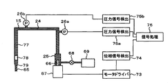
- the sample probe 15 is connected to a metering pump 25 by a dispensing channel 24, and a pressure sensor 26 and a vibrator 27 are provided in the middle of the dispensing channel 24.
- a throttle portion 65 having a small cross-sectional area is provided at the tip of the sample probe 15.
- the vibrator 27 is composed of a chamber 70 and a piezoelectric element 71.
- the metering pump 25 is provided with a plunger 66 driven by a drive mechanism 67.
- the metering pump 25 is connected to a pump 69 through a valve 68.
- the piezoelectric element 71 is connected to an oscillator 72, and the oscillator 72 is simultaneously connected to a phase signal detector 74.
- the pressure sensor 26 is connected to a pressure signal detector 75, and the phase signal detector 74 and the pressure signal detector 75 are connected to a signal processor 76.
- the sample probe 15 has a moving mechanism (not shown), and can move up and down and rotate to the sample container 10 and the reaction container 35.
- the device of this embodiment operates as follows.
- a sample to be examined such as blood is placed in the sample container 10 and set on the sample disk 12.
- the type of analysis required for each sample is input to the controller 60.
- a sample collected by the sample probe 15 is dispensed into a reaction container 35 arranged on the reaction disk 36, and a certain amount of reagent is supplied from the reagent container 40 installed on the reagent disk 41 or 42 to the reagent probe 20 or 21. And is stirred by the stirring device 30.
- the reaction disk 36 periodically rotates and stops, and photometry is performed by the spectroscopic detector 51 at the timing when the reaction container 35 passes in front of the light source 50.
- Photometry is repeated during a reaction time of 10 minutes, and then the reaction liquid in the reaction vessel 35 is discharged and washed by the vessel washing mechanism 45. In the meantime, in another reaction vessel 35, operations using different samples and reagents are performed in parallel. Data measured by the spectroscopic detector 51 is calculated by the computer 61, and the concentration of the component corresponding to the type of analysis is calculated and displayed.
- the valve 68 is opened and closed to fill the flow path of the sample probe 15 with the system liquid 77 supplied from the pump 69.
- the plunger 66 is lowered by the drive mechanism 67 and the separation air 78 is sucked.
- the sample probe 15 is lowered into the sample container 10, and the plunger 66 is lowered by a predetermined amount with the tip immersed in the sample, and the sample is sucked into the probe.
- the suction liquid 79 is a sample.
- the probe After the suction, the probe is raised and stopped, and a sine wave signal is applied from the oscillator 72 to the piezoelectric element 71 to apply a sine wave vibration from the chamber 70 to the system liquid 77.
- the pressure fluctuation during that time is detected by the pressure sensor 26, amplified by the pressure signal detector 75, and sent to the signal processor 76.
- a phase signal detector 74 detects a sine wave phase signal from the oscillator 72 and sends it to the signal processor 76.
- the signal processor 76 determines whether or not there is an abnormality in suction based on the pressure signal and the phase signal. If there is no abnormality, a signal is sent to the controller 60 to continue the operation, and the sample probe 15 is moved onto the reaction vessel 35.
- the sample is discharged and the analysis is continued.
- the sample probe 15 cleans the inside and outside by opening and closing the valve 68 to prepare for the next analysis. If it is determined that there is an abnormality in the suction, the analysis is stopped, an alarm is displayed, and the sample probe 15 is cleaned and returns.
- the return operation is selected from among other things such as re-dispensing except for the cause of the abnormality, moving to inspection of another sample, and stopping the apparatus.
- FIG. 3 shows an example of a pressure signal in this embodiment.
- the horizontal axis is time, and the vertical axis is pressure.
- the throttle portion 65 is shown.
- normal 1 contains a liquid with a viscosity equivalent to the lower limit of the range that a normal sample can take
- normal 2 is the average that a normal sample can take If a liquid with a viscosity equivalent to the typical viscosity is contained, the clogging corresponds to a case with an abnormally high viscosity liquid.
- FIG. 4 is a graph showing the characteristics of the pressure amplitude with respect to the excitation frequency in the configuration of this example.
- the horizontal axis is frequency and the vertical axis is pressure amplitude. From the graph, there is a resonance frequency having a maximum amplitude in the vicinity of 50 Hz, and the difference in amplitude due to viscosity is large, but the difference in amplitude is small at a frequency higher than the resonance frequency. Therefore, the excitation frequency may take a value near the resonance frequency.
- sinusoidal vibration is forcibly applied to the system liquid 77 inside the dispensing flow path system, and the amplitude and phase shift of the AC component of the pressure fluctuation are detected. It is possible to detect an empty sucking state in which air is contained in 65, to avoid a shortage of dispensing amount by discharging the sample to the reaction vessel 35 in the empty sucking state, and to analyze a sample with a correct amount with high accuracy. It is possible to provide an automatic analyzer.
- the present embodiment it is possible to detect a state in which abnormally high-viscosity liquid or foreign matter is mixed in the throttle portion 65 at the tip of the sample probe 15, so that it is possible to detect the state by discharging the sample to the reaction container 35 in the clogged state. It is possible to provide an automatic analyzer capable of avoiding a shortage of injection volume and analyzing a sample with a correct amount and high accuracy.
- the detection of the idling or clogging state is detected using the AC component of the excitation frequency using the phase signal of the oscillator 72, it is affected by the noise applied to the pressure fluctuation due to the mechanism operation or the like. Therefore, it is possible to provide an automatic analyzer that can accurately detect an empty suction or a clogging state and can perform an accurate analysis.
- the vibration is performed using the frequency near the resonance frequency where the pressure amplitude is large, the amplitude of the vibration may be small and does not affect the dispensing amount. Therefore, it is possible to provide an automatic analyzer capable of dispensing with high accuracy and capable of analyzing a sample with high accuracy.
- the detection can be performed while avoiding the timing of the sample suction operation and the movement of the sample probe 15, etc. It is possible to detect an empty suction or clogging with high accuracy without being affected by noise on the pressure signal due to operation.
- the detection operation can be performed while the sample probe 15 is moving. In this case, it is not necessary to devote time for detection, and an automatic analyzer having a high analysis capability per unit time can be provided.
- the narrowed portion 65 having a small inner diameter is provided at the tip of the sample probe 15, the ratio of the pressure loss of the tip portion is high in the pressure loss of the entire flow path. Therefore, it is possible to accurately detect whether the probe tip is filled with the sample.
- the suction state can be detected under the same conditions regardless of the suction amount setting.
- FIG. 5 is a graph plotting the pressure amplitude and the phase delay when the excitation frequency is 48 Hz, which is near the resonance frequency of the fluid. Not only the viscosity of the suction liquid 79 but also the amount of the separation air 78 is changed. Even if the suction liquid 79 has a constant viscosity, the pressure amplitude changes when the amount of the separation air 78 changes. When bubbles are mixed during sample suction, the amount of separation air 78 is equal to an excessive air state, but the pressure amplitude in that case becomes large and close to a clogged state.
- a standard prepared as a data table in advance is used as a reference for determining which region is normal suction on the map.
- the data table may be calculated and determined by fluid simulation or the like, or may be obtained by a simulated operation.
- the data table is corrected even if the characteristics change due to changes in the shape of the flow path member or changes in the physical property value of the system liquid 77 due to temperature changes.
- the suction state can always be detected with high accuracy.
- FIG. 6 is a graph plotting pressure amplitude and phase lag when the excitation frequency is 38 Hz, which is lower than the resonance frequency of the fluid.
- the frequency shown in this graph is also a value between the two resonance frequencies.
- the change in the amplitude is small depending on the conditions, but the change in the phase delay is large. Even when vibration is applied at this frequency, normal, idle suction, clogging, and excessive air can be determined by identifying the region on the amplitude-phase delay map.
- FIG. 7 shows the configuration of the main part of another embodiment of the present invention.
- the difference from the first embodiment is that the motor driver 73 for driving the drive mechanism 67 is connected to the phase signal detector 74 instead of providing the vibrator 27.
- the drive mechanism 67 includes a pulse motor and is driven by a pulse signal from the motor driver 73.
- a pulse having a frequency near the resonance frequency of the fluid is generated by the motor driver 73 to drive the drive mechanism 67.
- the plunger 66 descends while vibrating at the drive frequency.
- FIG. 8 An example of the pressure change at that time is shown in FIG.
- the amplitude and phase of the drive frequency component change in the case of idle suction, in the normal case, and in the case of clogging, and it is determined whether or not normal suction has been performed using this.
- the driving mechanism 67 having a small resolution is used in the configuration of this embodiment, and at the time of sample suction, the plunger 66 is lowered at a high speed, and then the plunger 66 is lowered by a small amount at a low frequency near the resonance frequency of the fluid. It is also possible to detect empty suction or clogging during the process.
- the suction time is short. Further, since it can be driven at a frequency higher than the natural frequency of the drive mechanism 67, it does not generate a large vibration, and it is possible to avoid dispensing accuracy failure and noise generation due to the vibration.
- FIG. 9 is a diagram showing the configuration of the main part of another embodiment of the present invention.
- the difference from FIG. 7 is that two pressure sensors 26a and 26b are installed in the middle of the dispensing flow path, and each is connected to the signal processor 76 through the pressure signal detectors 75a and 75b.
- the drive mechanism 67 is driven at a frequency near the resonance frequency of the fluid, the amplitudes of the excitation frequency components of the pressure fluctuations detected by the pressure sensors 26a and 26b are respectively extracted, and the ratio is calculated.
- the amplitude ratio is compared with a reference range set in advance. If the amplitude ratio is within the reference range, it is determined as normal suction, and if it is outside the reference range, abnormal suction such as idle suction or clogging is determined.
- the determination is made using the ratio of the amplitudes using the two pressure sensors, so that the influence due to the temperature drift of the pressure sensor, the change in the liquidity of the system liquid 77, and the like can be offset. It is possible to detect empty suction and clogging correctly regardless of changes.
- a reference is provided for a one-dimensional quantity called an amplitude ratio instead of a two-dimensional map of amplitude and phase delay, there is an advantage that the reference determination can be performed simply and in a short time.
- FIG. 10 is a perspective view of another embodiment of the present invention.
- pressure sensors 26c, 26d, vibrators 27c, 27d, and metering pumps 25c, 25d are also connected to the dispensing channels 24c, 24d connected to the reagent probes 20 and 21. It is.
- abnormalities such as empty suction and clogging are identified with respect to reagent dispensing in the same procedure as that performed for sample dispensing in the first embodiment.
- the resonance frequency changes depending on the system configuration, the excitation frequency is changed to a suitable frequency.
- the reagent container 40 it is possible to measure the amount of the reagent contained in the reagent container 40.
- the liquid level in each reagent container 40 is measured not when the reagent is dispensed but when the reagent container 40 is put into the apparatus or when the apparatus is started to be used every day.
- the reagent probe 20 or 21 is lowered with respect to the reagent container 40, the reagent probe 20 or 21 is sucked at a very low speed to detect the pressure fluctuation, and the height at which the reagent probe reaches the liquid level is detected.
- the reagent probe is lowered to a level where the liquid level should be and then aspirated in a small amount, and the amplitude and phase of the specific frequency component are detected to determine whether various amounts of reagent are contained.
- the amount of liquid in the reagent container can be detected without using an electric method such as a capacitance method, the amount of liquid in the reagent container is correctly detected without erroneous detection due to bubbles or the like. Can be detected.
- the amount of the reagent to be aspirated for detection can be small, and the consumption of the reagent can be reduced.
- the vibration generators 27c and 27d are not particularly provided, and a specific frequency component of fluctuation due to the low speed driving of the metering pumps 25c and 25d may be used, so that the vibration generator is unnecessary and the cost can be reduced. .
- Sample container 12 Sample disk 15 Sample probe 20 First reagent probe 21 Second reagent probe 24 Dispensing flow path 25 Metering pump 26 Pressure sensor 27 Exciter 30 Stirrer 35 Reaction container 36 Reaction disk 40 Reagent container 41 First reagent Disk 42 Second reagent disk 45 Container cleaning mechanism 50 Light source 51 Spectroscopic detector 60 Controller 61 Computer 65 Restriction section 66 Plunger 67 Drive mechanism 68 Valve 69 Pump 70 Chamber 71 Piezoelectric element 72 Oscillator 73 Motor driver 74 Phase signal detector 75 Pressure signal Detector 76 Signal processor 77 System liquid 78 Separation air 79 Suction liquid
Landscapes
- Life Sciences & Earth Sciences (AREA)
- Physics & Mathematics (AREA)
- Health & Medical Sciences (AREA)
- Chemical & Material Sciences (AREA)
- Analytical Chemistry (AREA)
- Biochemistry (AREA)
- General Health & Medical Sciences (AREA)
- General Physics & Mathematics (AREA)
- Immunology (AREA)
- Pathology (AREA)
- Hydrology & Water Resources (AREA)
- Automatic Analysis And Handling Materials Therefor (AREA)
Abstract
分注プローブで試料や試薬の吸引時に空吸いや詰まりが発生した場合分注不良が発生する。試料容器(10)から反応容器(35)へ試料を分注する分注機構(15)と、前記反応容器(35)の内容物を分析する分析手段(61)とを備えた自動分析装置において、前記分注機構(15)は、ノズル内の圧力を変化させる圧力発生機構(69)と、該ノズルと圧力発生機構(69)を接続し、内部に圧力伝達媒体を保持する分注流路(24)からなり、流路内の圧力伝達媒体に特定周波数の振動を与える加振器(27)と、該流路内の圧力を検出する圧力センサ(26)を有し、該圧力センサ(26)の出力から抽出した該特定周波数の成分の振幅または位相差に基づいて前記ノズル内に試料が正常に吸引されたかどうかを検出する機構(76)を備えたことを特徴とする自動分析装置。
Description
本発明は血液等の成分を自動的に分析する自動分析装置に関するものである。
自動分析装置は、血液や尿などの生体試料からなるサンプルをサンプル容器から反応ライン上の反応容器へサンプルを分注し、更に試薬容器から反応ライン上の反応容器へ試薬を分注し、サンプルと試薬の混合液を光度計の如き測定手段によって測定して定性或いは定量分析を行う。
サンプル、試薬共に分注動作の際には分注対象の液体内へ分注プローブの先端を浸漬させるが、その浸漬深さが大きいほどプローブ外壁への液体付着量が増しコンタミネーションが大きくなる。そこで、分注プローブの浸漬深さを極力低減するために、容器内の液体の液面を検出しプローブの先端が液面より僅かに下に達した位置でプローブの下降動作を停止させ、次いでプローブ内へ所定量の液体を吸引するように動作制御する手法が一般的である。サンプルの液面を検出する手段としては、サンプルプローブとサンプル間の静電容量を測定する方法などが使われている。この方法では、サンプルプローブとサンプルが接触すると静電容量が大きく変化することを利用して液面を検出している。
このようなサンプルプローブを用いたサンプル吸引時にオペレータの分注作業時の不具合等により検体、又は試薬の液面上部に膜、或いは泡が生成されている場合がある。この場合、分注プローブ先端が液面上の膜、或いは泡に接触した時点で静電容量が大きく変化するため、膜や泡を液面として検知し、既設の液面から僅かに下として設定されているプローブ浸漬高さでは液面に到達できない可能性がある。すなわち、引き続き行われる吸引動作にて、液体ではなく定量未満の液体、或いは空気を吸引し期待値とは異なる分析結果を出力する可能性を有していた。この問題を解決するため特許文献1では吸引流路に圧力センサを設け、吸引動作停止後における吸引流路内の圧力を検知し、吸引動作中或いは吸引動作後の圧力値を閾値と比較することにより、吸引流路の詰まり又は吸引量不足を検出する方法が開示されている。
特許文献1記載の方法では吸引動作中、或いは吸引動作後の特定期間の圧力の平均値または変化量を予め定めておいた閾値と比較することで、吸引量の不足を検知している。
しかし、吸引動作中や吸引動作後は圧力の変動が大きく、それに対して正常吸引時と吸引不足時の圧力の差は小さいので、吸引不足を正確に判定することは困難であった。
更に、吸引する検体、試薬の粘性係数などは一定でなく、また吸引量も測定項目により変化するので、正常吸引時の圧力の値は一定値ではなく、全ての条件で正常吸引と吸引不足を判別することは困難であった。
上記課題を解決するために、本発明による自動分析装置は、試料容器から反応容器へ試料を分注する分注機構と、前記反応容器の内容物を分析する分析手段を備え、前記分注機構は、移動可能な分注プローブと、定量の吸引、吐出が可能な定量ポンプと、分注プローブと定量ポンプを結び、内部にシステム液を保持する分注流路からなり、流路内のシステム液に対して特定周波数の振動を与える加振器と、分注流路内の圧力を検出する圧力センサを有し、圧力センサの出力から抽出した該特定周波数の成分の振幅または位相差に基づいて吸引動作中に試料が正常に吸引されたかどうかを検出する機構を備える。
また、加振器の振動の位相を示す信号と、圧力センサの出力信号を用いて信号処理するとよい。
また、試料の吸引時に、空吸いの発生と、詰まりの発生をそれぞれ検出するとよい。
また、分注プローブの先端に先端部に向かって内径を小さくする絞り部を有するとよい。
また、特定周波数は、分注流路内の流体の圧力振幅が極大となる共振周波数の付近の周波数であるとよい。
また、圧力変動の特定周波数の振幅と、加振器の振動に対する圧力変動の位相遅れを検出し、振幅と位相遅れの関係を予め定めておいた基準と比較することで、試料の吸引の異常の有無を判断するとよい。
また、圧力変動の検出は、試料の吸引の終了から吐出の開始までの間に行われるとよい。
また、圧力変動の検出は、分注プローブの移動中に行われるとよい。
また、加振器は、パルス駆動の定量ポンプと兼用されるとよい。
また、分注流路の2箇所以上に圧力センサが設けられ、複数の圧力センサの信号の比較により試料の吸引の異常の有無を検出してもよい。
本発明の自動分析装置は、分注流路に圧力センサと加振機構を設け、圧力変動の加振周波数成分の振幅と位相差を用いて吸引が正常に行われたかを判定するため、液面上に膜或いは泡が存在して所定量の液体が吸引できなかった場合でも正確にそれを検知できる機能を備えた自動分析装置を提供可能である。
以下、図面を用いて本発明の実施の形態を説明する。
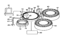
図1、図2は本発明を適用できる自動分析装置の1実施例を示す。
試料を保持するサンプル容器10を複数搭載可能なサンプルディスク12、試薬を保持する試薬容器40を複数搭載可能な第1試薬ディスク41および第2試薬ディスク42、周上に複数の反応容器35を配置した反応ディスク36、サンプル容器10から吸引した試料を反応容器35に分注するサンプルプローブ15、第1試薬ディスク41内の試薬容器40から吸引した試薬を反応容器35に分注する第1試薬プローブ20、第2試薬ディスク42内の試薬容器40から吸引した試薬を反応容器35に分注する第2試薬プローブ21、反応容器35内の液体を撹拌する攪拌装置30、反応容器35を洗浄する容器洗浄機構45、反応ディスク36の外周付近に設置された光源50、分光検出器51、分光検出器51に接続されたコンピュータ61、装置全体の動作を制御し、外部とのデータの交換を行うコントローラ60からなる。サンプルプローブ15は、分注流路24により定量ポンプ25と接続され、分注流路24の途中には圧力センサ26と加振器27が設けられる。
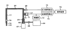
図2に詳細を示すように、サンプルプローブ15の先端には断面積の小さい絞り部65が設けられている。加振器27は、チャンバ70および圧電素子71で構成されている。
定量ポンプ25には駆動機構67で駆動されるプランジャ66が設けられている。定量ポンプ25は、バルブ68を通してポンプ69に接続されている。圧電素子71は発振器72と接続され、発振器72は同時に位相信号検出器74に接続している。圧力センサ26は圧力信号検出器75に接続し、位相信号検出器74と圧力信号検出器75は信号処理器76に接続している。サンプルプローブ15は図示しない移動機構を有しており、上下、回転してサンプル容器10と反応容器35に移動できる。
定量ポンプ25には駆動機構67で駆動されるプランジャ66が設けられている。定量ポンプ25は、バルブ68を通してポンプ69に接続されている。圧電素子71は発振器72と接続され、発振器72は同時に位相信号検出器74に接続している。圧力センサ26は圧力信号検出器75に接続し、位相信号検出器74と圧力信号検出器75は信号処理器76に接続している。サンプルプローブ15は図示しない移動機構を有しており、上下、回転してサンプル容器10と反応容器35に移動できる。
本実施例の装置は以下のように動作する。サンプル容器10には血液等の検査対象の試料が入れられ、サンプルディスク12にセットされる。それぞれの試料で必要な分析の種類はコントローラ60に入力される。サンプルプローブ15によって採取された試料は反応ディスク36に並べられている反応容器35に一定量分注され、一定量の試薬が試薬ディスク41または42に設置された試薬容器40から試薬プローブ20または21により分注され、攪拌装置30にて攪拌される。反応ディスク36は周期的に回転、停止を繰り返し、反応容器35が光源50の前を通過するタイミングで分光検出器51にて測光が行われる。10分間の反応時間の間に測光を繰り返し、その後、容器洗浄機構45で反応容器35内の反応液の排出および洗浄がなされる。それらの間に別の反応容器35では、別の試料、試薬を用いた動作が並行して実施される。分光検出器51にて測光したデータはコンピュータ61で演算し、分析の種類に応じた成分の濃度を算出して表示される。
サンプルプローブ15の動作を図2を用いて詳細に説明する。試料を吸引する前に、まずバルブ68を開閉してサンプルプローブ15の流路内部をポンプ69から供給されるシステム液77で満たす。次にサンプルプローブ15の先端が空中にある状態で、駆動機構67によりプランジャ66を下降動作し、分離空気78を吸引する。次にサンプルプローブ15をサンプル容器10の中に下降し、先端が試料内に浸かった状態でプランジャ66を所定量下降して試料をプローブ内に吸引する。この場合吸引液79は試料である。吸引後、プローブを上昇して停止し、発振器72から正弦波の信号を圧電素子71に加えてチャンバ70からシステム液77に正弦波の振動を与える。その間の圧力変動を圧力センサ26で検出し、圧力信号検出器75で増幅されて信号処理器76に送られる。同時に発振器72からは位相信号検出器74で正弦波の位相信号を検出され、信号処理器76に送られる。信号処理器76では、圧力信号と位相信号を元に吸引の異常の有無を判別し、異常が無ければ、コントローラ60に信号を与えて動作を継続し、サンプルプローブ15を反応容器35上に移動して試料を吐出し、分析を続行する。サンプルプローブ15は試料吐出後、バルブ68の開閉で内外部を洗浄し、次の分析に備える。吸引に異常があったと判断された場合は、その分析は中止し、アラームを表示して、サンプルプローブ15は洗浄されて、復帰動作をする。復帰動作は、異常の原因を除いて再分注する、別の試料の検査に移る、装置を停止するなどの中から選択される。
図3に、本実施例での圧力信号の例を示す。横軸は時間、縦軸は圧力である。条件として、絞り部65部分に4種類の粘性の異なる流体を入れた場合を示している。空吸いは、絞り部65部分に空気が入っている場合、正常1は正常な試料がとり得る範囲の下限と同等の粘性の液体が入っている場合、正常2は正常な試料がとり得る平均的な粘性と同等の粘性の液体が入っている場合、詰まりは異常な高粘性の液体が入っている場合に相当する。グラフをみてわかるように、粘性の違いにより圧力の振幅と位相が変わっており、振幅或いは位相差を判別することで正常に吸引できているか、或いは空吸いまたは詰まりのような異常がおきているかが識別できる。
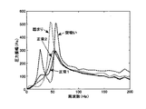
図4は本実施例の構成での、加振周波数に対する圧力振幅の特性を示したグラフである。横軸が周波数、縦軸が圧力振幅である。グラフより50Hz付近に振幅が最大となる共振周波数があり、粘性による振幅の差が大きいが、共振周波数より高い周波数では振幅の差が小さくなっている。したがって、加振周波数は共振周波数付近の値をとるとよい。
本実施例では、分注流路系の内部のシステム液77に正弦的な振動を強制的に与え、圧力変動の交流成分の振幅と位相ずれを検出するので、サンプルプローブ15の先端の絞り部65に空気が入っている空吸い状態を検出でき、空吸い状態で試料を反応容器35に吐出することによる分注量不足を避けることができ、正しい量での高精度な試料の分析ができる自動分析装置を提供することが可能である。
また、本実施例では、サンプルプローブ15の先端の絞り部65に異常に高粘性の液体や異物が混入している状態を検出できるので、詰まり状態で試料を反応容器35に吐出することによる分注量不足を避けることができ、正しい量での高精度な試料の分析ができる自動分析装置を提供することが可能である。
また、本実施例では、空吸いや詰まり状態の検出を、発振器72の位相信号を用いて加振周波数の交流成分を用いて検出するので、機構動作などにより圧力変動に加わる雑音の影響を受けにくく、正確に空吸いや詰まり状態の検出が可能であり、正確な分析が可能な自動分析装置を提供できる。
また、本実施例では、圧力変動の絶対値ではなく交流成分を検出するため、圧力センサのドリフトや液面高さの違いなどによる圧力測定値の平均値に差が生じても影響されることが無く、空吸いや詰まり状態を正しく検知することができ、正しい量での高精度な試料の分析が可能な自動分析装置が提供できる。
また、本実施例では、圧力振幅が大きい共振周波数付近の周波数を用いて加振するので、加振の振幅は小さくてよく、分注量に影響を与えることがない。そのため、精度の高い分注が可能で、高精度の試料の分析が可能な自動分析装置が提供できる。
また、本実施例では、圧力変動の交流成分の振幅の違いにより、空吸いの場合と詰まりの場合をそれぞれ検出可能である。そのため、異常の種類により、別々の対処を選択して、効率よく復帰することが可能であり、処理能力の高い自動分析装置を提供できる。
また、本実施例では、加振器27による加振によって圧力変動を起こして検出するため、試料の吸引動作やサンプルプローブ15の移動などのタイミングを避けて検出をさせることが可能であり、機構動作による圧力信号への雑音の影響を受けないで空吸いや詰まり状態を精度よく検知できる。
また、検出動作はサンプルプローブ15の移動中に行うことも可能であり、その場合は検出のために時間を割く必要が無く、単位時間当たりの分析能力の高い自動分析装置が提供できる。
また、本実施例の場合、サンプルプローブ15の先端に内径の小さい絞り部65が設けられているため、流路全体の圧力損失の中で先端部分の圧力損失の占める割合が高い。そのため、プローブ先端が試料で満たされているかどうかを正確に検出できる。
また、本実施例の場合、絞り部65の容積は小さいので、設定される最小の吸引量での場合でも絞り部65の内部は吸引液79で満たされる。したがって吸引量の設定に関わらず同じ条件で吸引状態を検知できる。
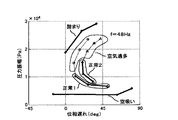
図5は加振周波数を、流体の共振周波数付近である48Hzにしたときの、圧力振幅と位相遅れをプロットしたグラフである。吸引液79の粘性だけでなく、分離空気78の量を変化させている。吸引液79の粘性が一定でも、分離空気78の量が変わると圧力振幅が変化する。試料吸引時に気泡が混じると、分離空気78の量が多い空気過多の状態と等しくなるが、その場合の圧力振幅は大きくなり、詰まり状態と近くなる。圧力振幅のみを比較するのでは、正常な状態と、空気過多の状態と、詰まりの状態を判別することは困難であるが、位相遅れを同時に算出し、マップ上の領域で識別することでそれぞれの状態を正しく判別することが可能である。マップ上でどの領域が正常吸引と判断するかの基準は、事前にデータテーブルとして用意しておいたものを用いる。データテーブルは、流体シミュレーションなどで計算して決定してもよいし、模擬的な動作で求めたものでもよい。
この場合は、完全な空吸いでなく気泡を混入して吸引した場合もそれを検出でき、吐出量不足による不正確な分析を避けることが可能である。
また、この実施例の場合は、事前にデータテーブルを用意するので、流路部材の形状変化や、温度変化によるシステム液77の物性値の変化などにより、特性が変化してもデータテーブルを修正することができ、常に高精度に吸引状態を検知することができる。
図6は加振周波数を、流体の共振周波数より低い38Hzにしたときの、圧力振幅と位相遅れをプロットしたグラフである。この系の場合50Hz付近以外に30Hz付近にも共振周波数があるが、このグラフで示した周波数は2つの共振周波数の間の値でもある。
グラフを見ると、図5の場合とは異なり、条件によって振幅の変化は小さいが位相遅れの変化が大きい。この周波数で加振した場合も、振幅-位相遅れのマップ上の領域で識別することで、正常、空吸い、詰まり、空気過多を判別することができる。
グラフを見ると、図5の場合とは異なり、条件によって振幅の変化は小さいが位相遅れの変化が大きい。この周波数で加振した場合も、振幅-位相遅れのマップ上の領域で識別することで、正常、空吸い、詰まり、空気過多を判別することができる。
また、この場合は特に振幅でなく位相遅れに違いが生じるため、ノイズやセンサのドリフトなどの影響を受けにくく、分注不足を精度よく検出することが可能である。
図7に本発明の別の実施例の主要部分の構成を示す。第一実施例との違いは、加振器27を設けない代わりに、駆動機構67を駆動するモータドライバ73が位相信号検出器74に接続されている。駆動機構67はパルスモータを含んでおり、モータドライバ73からのパルス信号で駆動される。
この実施例で、試料の吸引時に流体の共振周波数の付近の周波数のパルスをモータドライバ73で発生して駆動機構67を駆動する。それによりプランジャ66が駆動周波数で振動しながら下降する。そのときの圧力変化の例を図8に示す。図8のグラフでわかるように、空吸いの場合、正常の場合、詰まりの場合で駆動周波数成分の振幅及び位相が変化しており、それを利用して正常に吸引できたかどうかを判別する。
この実施例の場合は、加振器27を追加すること無しに吸引状態を高精度に検知できるので、安価でかつ精度高い分析が可能な自動分析装置を提供できる。
またこの実施例の場合は、試料の吸引時に状態を検知できるので、吸引後に検知のための時間をとる必要が無く、高精度でかつ高処理能力の自動分析装置を提供できる。
また、この実施例の場合は、モータドライバ73の位相信号を用いて駆動周波数成分のみを抽出して処理するので、圧力波形に含まれる吸引開始の衝撃や振動などによる雑音の影響を除去でき、空吸いや詰まりの状態を精度よく検知が可能である。
また、本実施例の構成で分解能の小さい駆動機構67を用い、試料吸引時には高い周波数でプランジャ66を高速に下降させ、その後で流体の共振周波数付近の低い周波数でわずかの量だけプランジャ66を下降させ、その最中に空吸いや詰まりを検知するようにすることも可能である。
その場合は、試料の吸引は高速で行うために、吸引時間が短くてすむ。また駆動機構67の固有振動数より高い周波数で駆動できるために、大きな振動を発生することがなく、振動による分注精度不良や騒音発生を避けることが可能である。
またこの場合、駆動機構67の分解能が小さい上に、検知のために必要な吸引パルス数は数パルス程度なので、追加吸引はごく微量であり、分注量に与える影響は小さい。
図9は本発明の別の実施例の主要部分の構成を示す図である。図7との違いは、分注流路の途中に2つの圧力センサ26a、26bが設置され、それぞれが圧力信号検出器75a、75bを通して信号処理器76に接続されている点である。この実施例では、駆動機構67を流体の共振振動数付近の周波数で駆動し、圧力センサ26aと26bが検出した圧力変動の加振周波数成分の振幅をそれぞれ抽出してその比を計算する。事前に設定しておいた基準範囲と振幅比を比較し、振幅比が基準範囲内なら正常吸引、基準範囲外なら空吸いや詰まりなどの異常吸引と判断する。
本実施例の場合は、2つの圧力センサを用いて振幅の比を用いて判断を行うため、圧力センサの温度ドリフトや、システム液77の液性変化などによる影響を相殺することができ、環境変化によらず正しく空吸いや詰まりを検出できる。
また、本実施例では、振幅と位相遅れの2次元マップではなく、振幅比という1次元量に対して基準を設けるので、基準決めが単純で短時間に行えるという利点がある。
また、本実施例では、2つの圧力センサの信号を使うため、サンプルプローブ15の移動中など外部から圧力信号に雑音の入りやすい条件で測定しても雑音を相殺しやすく、他の機構の動作と同時に実行できるので、処理能力の高い自動分析装置が提供できる。
図10は本発明の別の実施例の斜視図である。第一実施例との違いは、試薬プローブ20および21に接続する分注流路24c、24dにも圧力センサ26c、26d、加振器27c、27d、定量ポンプ25c、25dが接続されている点である。本実施例では、第一実施例で試料の分注に対して行っていると同様の手順で、試薬の分注に対して空吸いや詰まりなどの異常を識別する。但し、系の構成により共振周波数は変わるので、加振周波数を適した周波数に変える。
本実施例では、試薬分注での空吸いや詰まりなどの異常も検出できるため、反応容器に試薬が分注される量が不足することを避けることができ、高精度な試料の分析ができる自動分析装置を提供できる。
また、本実施例の構成の用途として、試薬容器40の中に入っている試薬の量を測定することが可能である。その場合、試薬分注時ではなく、試薬容器40を装置に入れた時や、毎日装置を使い始める時などに、各試薬容器40の中の液面高さを測定する。そのときは、試薬容器40に対して試薬プローブ20または21を下降させながら、微速度で吸引し、圧力変動を検出して、試薬プローブが液面に達した高さを検出する。または、液面があるべき高さまで試薬プローブを下降させてから微量吸引し、特定周波数成分の振幅と位相を検出して、諸定量の試薬が入っているかを判別する。
この方法によれば、静電容量方式などの電気的な方法によらずに試薬容器内の液量を検出できるため、泡などによって誤った検出をすることがなく、正しく試薬容器内の液量が検出できる。
また、この方法によれば、微量の液体を吸引中の圧力変動から試薬の有無を検出するため、検出のために吸引する試薬の量が微量で済み、試薬の消費を少なくすることができる。
この場合、特に加振器27cおよび27dを設けず、定量ポンプ25c、25dの低速駆動による変動の特定周波数成分を用いてもよく、そうすることで加振器が不要で低コスト化が実現できる。
10 サンプル容器
12 サンプルディスク
15 サンプルプローブ
20 第1試薬プローブ
21 第2試薬プローブ
24 分注流路
25 定量ポンプ
26 圧力センサ
27 加振器
30 攪拌装置
35 反応容器
36 反応ディスク
40 試薬容器
41 第1試薬ディスク
42 第2試薬ディスク
45 容器洗浄機構
50 光源
51 分光検出器
60 コントローラ
61 コンピュータ
65 絞り部
66 プランジャ
67 駆動機構
68 バルブ
69 ポンプ
70 チャンバ
71 圧電素子
72 発振器
73 モータドライバ
74 位相信号検出器
75 圧力信号検出器
76 信号処理器
77 システム液
78 分離空気
79 吸引液
12 サンプルディスク
15 サンプルプローブ
20 第1試薬プローブ
21 第2試薬プローブ
24 分注流路
25 定量ポンプ
26 圧力センサ
27 加振器
30 攪拌装置
35 反応容器
36 反応ディスク
40 試薬容器
41 第1試薬ディスク
42 第2試薬ディスク
45 容器洗浄機構
50 光源
51 分光検出器
60 コントローラ
61 コンピュータ
65 絞り部
66 プランジャ
67 駆動機構
68 バルブ
69 ポンプ
70 チャンバ
71 圧電素子
72 発振器
73 モータドライバ
74 位相信号検出器
75 圧力信号検出器
76 信号処理器
77 システム液
78 分離空気
79 吸引液
Claims (10)
- 試料容器から反応容器へ試料を分注する分注機構と、
前記反応容器の内容物を分析する分析手段とを備えた自動分析装置において、
前記分注機構は、ノズル内の圧力を変化させる圧力発生機構と、該ノズルと圧力発生機構を接続し、内部に圧力伝達媒体を保持する分注流路からなり、
流路内の圧力伝達媒体に特定周波数の振動を与える加振器と、該流路内の圧力を検出する圧力センサを有し、
該圧力センサの出力から抽出した該特定周波数の成分の振幅または位相差に基づいて前記ノズル内に試料が正常に吸引されたかどうかを検出する機構を備えたことを特徴とする自動分析装置。 - 請求項1の自動分析装置において、
前記分注機構は、加振器の振動の位相を示す信号と、圧力センサの出力信号を用いて信号処理することを特徴とする自動分析装置。 - 請求項1の自動分析装置において、
試料の吸引時に、空吸いの発生と、詰まりの発生をそれぞれ検出する
ことを特徴とする自動分析装置。 - 請求項1~3の自動分析装置において、
分注プローブの先端に先端部に向かって内径を小さくする絞り部を有することを特徴とする自動分析装置。 - 請求項1~4の自動分析装置において、
特定周波数は、分注流路内の流体の圧力振幅が極大となる共振周波数の付近の周波数であることを特徴とする自動分析装置。 - 請求項1~5の自動分析装置において、
圧力変動の特定周波数の振幅と、加振器の振動に対する圧力変動の位相遅れを検出し、振幅と位相遅れの関係を予め定めておいた基準と比較することで、試料の吸引の異常の有無を判断することを特徴とする自動分析装置。 - 請求項6の自動分析装置において、
前記圧力変動の検出は、試料の吸引の終了から吐出の開始までの間に行われることを特徴とする自動分析装置。 - 請求項1~7の自動分析装置において、
圧力変動の検出は、分注プローブの移動中に行われることを特徴とする自動分析装置。 - 請求項1~8の自動分析装置において、
加振器は、パルス駆動の定量ポンプと兼用されることを特徴とする自動分析装置。 - 請求項1~9の自動分析装置において、
分注流路の2箇所以上に圧力センサが設けられ、複数の圧力センサの信号の比較により試料の吸引の異常の有無を検出することを特徴とする自動分析装置。
Priority Applications (3)
| Application Number | Priority Date | Filing Date | Title |
|---|---|---|---|
| CN201180036069.4A CN103026241B (zh) | 2010-07-27 | 2011-06-30 | 自动分析装置 |
| US13/811,938 US20130121880A1 (en) | 2010-07-27 | 2011-06-30 | Automatic analyzer |
| EP11812213.4A EP2600158A1 (en) | 2010-07-27 | 2011-06-30 | Autoanalyzer |
Applications Claiming Priority (2)
| Application Number | Priority Date | Filing Date | Title |
|---|---|---|---|
| JP2010167678A JP5277214B2 (ja) | 2010-07-27 | 2010-07-27 | 自動分析装置 |
| JP2010-167678 | 2010-07-27 |
Publications (1)
| Publication Number | Publication Date |
|---|---|
| WO2012014620A1 true WO2012014620A1 (ja) | 2012-02-02 |
Family
ID=45529839
Family Applications (1)
| Application Number | Title | Priority Date | Filing Date |
|---|---|---|---|
| PCT/JP2011/065024 Ceased WO2012014620A1 (ja) | 2010-07-27 | 2011-06-30 | 自動分析装置 |
Country Status (5)
| Country | Link |
|---|---|
| US (1) | US20130121880A1 (ja) |
| EP (1) | EP2600158A1 (ja) |
| JP (1) | JP5277214B2 (ja) |
| CN (1) | CN103026241B (ja) |
| WO (1) | WO2012014620A1 (ja) |
Cited By (8)
| Publication number | Priority date | Publication date | Assignee | Title |
|---|---|---|---|---|
| CN104854459A (zh) * | 2012-12-19 | 2015-08-19 | 株式会社日立高新技术 | 自动分析装置 |
| US11058278B2 (en) | 2018-04-30 | 2021-07-13 | Lg Electronics Inc. | Nozzle for cleaner |
| TWI736882B (zh) * | 2018-04-30 | 2021-08-21 | 南韓商Lg電子股份有限公司 | 用於清掃機的吸嘴 |
| US11096536B2 (en) | 2018-04-30 | 2021-08-24 | Lg Electronics Inc. | Nozzle for cleaner |
| US11154172B2 (en) | 2018-04-30 | 2021-10-26 | Lg Electronics Inc. | Nozzle for cleaner |
| US11191415B2 (en) | 2018-04-30 | 2021-12-07 | Lg Electronics Inc. | Nozzle for cleaner |
| US11426041B2 (en) | 2018-07-30 | 2022-08-30 | Lg Electronics Inc. | Nozzle for cleaner |
| US12616345B2 (en) | 2018-04-30 | 2026-05-05 | Lg Electronics Inc. | Nozzle for cleaner |
Families Citing this family (27)
| Publication number | Priority date | Publication date | Assignee | Title |
|---|---|---|---|---|
| JP5865633B2 (ja) | 2011-09-01 | 2016-02-17 | 株式会社日立ハイテクノロジーズ | 自動分析装置 |
| EP3044596A4 (en) * | 2013-09-09 | 2017-03-15 | Abbott Laboratories | Systems and methods for incubating samples |
| CN103575925B (zh) * | 2013-11-14 | 2015-04-01 | 宋筱亮 | 一种具有自动检测功能的加样针 |
| WO2015092844A1 (ja) * | 2013-12-16 | 2015-06-25 | 株式会社島津製作所 | 液採取装置及びその液採取装置を備えた自動分析装置 |
| WO2015174226A1 (ja) * | 2014-05-15 | 2015-11-19 | 株式会社日立ハイテクノロジーズ | 自動分析装置 |
| CN110452808B (zh) | 2014-07-08 | 2022-11-22 | 国立研究开发法人产业技术综合研究所 | 核酸扩增装置、核酸扩增方法以及核酸扩增用芯片 |
| CN104190344B (zh) * | 2014-07-25 | 2016-01-13 | 北京泊菲莱科技有限公司 | 光辐照多样品平行反应装置 |
| JP6649942B2 (ja) * | 2015-02-23 | 2020-02-19 | 株式会社日立ハイテクノロジーズ | 自動分析装置 |
| JP2018510363A (ja) | 2015-02-27 | 2018-04-12 | ハイコア バイオメディカル エルエルシー | 複数のキュベットの内容物を浮かせて洗うための装置と方法 |
| CN104777323A (zh) * | 2015-03-30 | 2015-07-15 | 苏州长光华医生物医学工程有限公司 | 化学发光免疫分析仪加样针堵孔报警电路 |
| CN106706940B (zh) * | 2016-11-15 | 2018-08-17 | 上海德孚生物医疗科技有限公司 | 生化分析加样装置 |
| TWI766942B (zh) | 2017-02-13 | 2022-06-11 | 美商海科生醫有限責任公司 | 透過利用瞬態和穩態間隔振動移液管來混合流體或介質的設備和方法 |
| WO2018179190A1 (ja) * | 2017-03-29 | 2018-10-04 | 株式会社日立産機システム | 給液式気体圧縮機 |
| KR101933062B1 (ko) | 2017-09-19 | 2019-03-15 | 서강대학교산학협력단 | 이송대상유체의 압력을 측정하는 펌프, 이를 이용하는 유체운송 시스템과 그 시스템의 동작 방법 |
| CN107643699B (zh) * | 2017-09-30 | 2019-11-01 | 迈克医疗电子有限公司 | 取液控制方法、装置及取液系统 |
| JP6946202B2 (ja) * | 2018-01-15 | 2021-10-06 | 株式会社日立ハイテク | 自動分析装置 |
| CN108061590A (zh) * | 2018-01-29 | 2018-05-22 | 淮阴工学院 | 气压式吸液探测器 |
| EP3779467B1 (en) * | 2018-03-28 | 2023-09-06 | Hitachi High-Tech Corporation | Automated analysis device |
| JP6914887B2 (ja) * | 2018-05-16 | 2021-08-04 | 日本電子株式会社 | 自動分析装置、および自動分析方法 |
| CN109026653B (zh) * | 2018-09-29 | 2025-01-17 | 瞬知(广州)健康科技有限公司 | 一种基于微流控泵的输注异常状态检测及控制系统 |
| JP7255129B2 (ja) | 2018-10-12 | 2023-04-11 | ソニーグループ株式会社 | 注入装置、注入方法、及び注入プログラム |
| EP4050342A4 (en) * | 2019-10-24 | 2023-12-20 | Hitachi High-Tech Corporation | DEVICE AND METHOD FOR AUTOMATICALLY ANALYZING REAGENT DISPENSION |
| CN110794159A (zh) * | 2019-11-04 | 2020-02-14 | 广州科方生物技术股份有限公司 | 加样机构 |
| CN110794153A (zh) * | 2019-11-04 | 2020-02-14 | 广州科方生物技术股份有限公司 | 自动干式荧光免疫分析仪 |
| JP7269869B2 (ja) * | 2019-12-05 | 2023-05-09 | 株式会社日立ハイテク | 自動分析装置及び分注方法 |
| WO2025013646A1 (ja) * | 2023-07-11 | 2025-01-16 | 株式会社日立ハイテク | 自動分析装置 |
| WO2025158807A1 (ja) * | 2024-01-23 | 2025-07-31 | 株式会社日立ハイテク | 自動分析装置、および自動分析装置における異常の有無を判定する方法 |
Citations (4)
| Publication number | Priority date | Publication date | Assignee | Title |
|---|---|---|---|---|
| JPH05256857A (ja) * | 1992-03-12 | 1993-10-08 | Hitachi Ltd | 分注機構 |
| JPH10227799A (ja) * | 1997-02-13 | 1998-08-25 | Aloka Co Ltd | 分注装置 |
| JP3151924B2 (ja) * | 1992-03-31 | 2001-04-03 | 株式会社島津製作所 | 分析装置の自動分注装置 |
| JP2007047083A (ja) * | 2005-08-11 | 2007-02-22 | Olympus Corp | 分注装置における配管内の気泡の有無判定方法および分注装置 |
Family Cites Families (13)
| Publication number | Priority date | Publication date | Assignee | Title |
|---|---|---|---|---|
| US5033858A (en) * | 1990-02-26 | 1991-07-23 | Westinghouse Electric Corp. | Detection of contaminants in a liquid stream |
| US5804698A (en) * | 1993-10-29 | 1998-09-08 | Uhp Corp. | Method and system for measuring fluid parameters by ultrasonic methods |
| JP4717312B2 (ja) * | 2000-02-29 | 2011-07-06 | ジェン−プローブ・インコーポレイテッド | 流体搬送プローブ |
| US6669909B2 (en) * | 2001-03-26 | 2003-12-30 | Allegro Technologies Limited | Liquid droplet dispensing |
| US20030022234A1 (en) * | 2001-05-31 | 2003-01-30 | Cawse James Norman | Method and system to conduct a combinatorial high throughput screening experiment |
| DE10132530A1 (de) * | 2001-07-09 | 2003-01-30 | Evotec Ag | Verfahren zur Überwachung der Funktionsfähigkeit einer Flüssigkeitsfördervorrichtung und Flüssigkeitsfördervorrichtung |
| JP4099822B2 (ja) * | 2002-07-26 | 2008-06-11 | セイコーエプソン株式会社 | ディスペンシング装置、ディスペンシング方法及び生体試料含有溶液吐出不良検出方法 |
| JP3903015B2 (ja) * | 2003-02-05 | 2007-04-11 | 株式会社日立ハイテクノロジーズ | 化学分析装置 |
| JP4045211B2 (ja) * | 2003-06-27 | 2008-02-13 | 株式会社日立ハイテクノロジーズ | 自動分析装置 |
| EP1596169B1 (en) * | 2004-05-14 | 2012-05-30 | F. Hoffmann-La Roche AG | Level sensor apparatus for detecting contact of a pipetting needle with a liquid in a vessel |
| DE202006010293U1 (de) * | 2005-07-22 | 2006-08-31 | Tecan Trading Ag | Pipettiergerät mit Computerprogrammprodukt zum Akzeptieren oder Verwerfen von pipettierten Flüssigkeitsproben |
| JP2008002897A (ja) * | 2006-06-21 | 2008-01-10 | Olympus Corp | 分注装置および自動分析装置 |
| US8545757B2 (en) * | 2009-01-30 | 2013-10-01 | Hitachi High-Technologies Corporation | Automatic analyzer and sample treatment apparatus |
-
2010
- 2010-07-27 JP JP2010167678A patent/JP5277214B2/ja active Active
-
2011
- 2011-06-30 WO PCT/JP2011/065024 patent/WO2012014620A1/ja not_active Ceased
- 2011-06-30 EP EP11812213.4A patent/EP2600158A1/en not_active Withdrawn
- 2011-06-30 US US13/811,938 patent/US20130121880A1/en not_active Abandoned
- 2011-06-30 CN CN201180036069.4A patent/CN103026241B/zh active Active
Patent Citations (4)
| Publication number | Priority date | Publication date | Assignee | Title |
|---|---|---|---|---|
| JPH05256857A (ja) * | 1992-03-12 | 1993-10-08 | Hitachi Ltd | 分注機構 |
| JP3151924B2 (ja) * | 1992-03-31 | 2001-04-03 | 株式会社島津製作所 | 分析装置の自動分注装置 |
| JPH10227799A (ja) * | 1997-02-13 | 1998-08-25 | Aloka Co Ltd | 分注装置 |
| JP2007047083A (ja) * | 2005-08-11 | 2007-02-22 | Olympus Corp | 分注装置における配管内の気泡の有無判定方法および分注装置 |
Cited By (28)
| Publication number | Priority date | Publication date | Assignee | Title |
|---|---|---|---|---|
| CN104854459A (zh) * | 2012-12-19 | 2015-08-19 | 株式会社日立高新技术 | 自动分析装置 |
| US11896188B2 (en) | 2018-04-30 | 2024-02-13 | Lg Electronics Inc. | Nozzle for cleaner |
| US11058278B2 (en) | 2018-04-30 | 2021-07-13 | Lg Electronics Inc. | Nozzle for cleaner |
| US11096536B2 (en) | 2018-04-30 | 2021-08-24 | Lg Electronics Inc. | Nozzle for cleaner |
| US11154172B2 (en) | 2018-04-30 | 2021-10-26 | Lg Electronics Inc. | Nozzle for cleaner |
| US11191415B2 (en) | 2018-04-30 | 2021-12-07 | Lg Electronics Inc. | Nozzle for cleaner |
| TWI769892B (zh) * | 2018-04-30 | 2022-07-01 | 南韓商Lg電子股份有限公司 | 清掃機 |
| US12551069B2 (en) | 2018-04-30 | 2026-02-17 | Lg Electronics Inc. | Nozzle for cleaner |
| US11517173B2 (en) | 2018-04-30 | 2022-12-06 | Lg Electronics Inc. | Nozzle for cleaner |
| US11517174B2 (en) | 2018-04-30 | 2022-12-06 | Lg Electronics Inc. | Nozzle for cleaner |
| US11659973B2 (en) | 2018-04-30 | 2023-05-30 | Lg Electronics Inc. | Nozzle for cleaner |
| TWI736882B (zh) * | 2018-04-30 | 2021-08-21 | 南韓商Lg電子股份有限公司 | 用於清掃機的吸嘴 |
| US11786093B2 (en) | 2018-04-30 | 2023-10-17 | Lg Electronics Inc. | Nozzle for cleaner |
| US12029364B2 (en) | 2018-04-30 | 2024-07-09 | Lg Electronics Inc. | Nozzle for cleaner |
| US12616345B2 (en) | 2018-04-30 | 2026-05-05 | Lg Electronics Inc. | Nozzle for cleaner |
| US11944249B2 (en) | 2018-04-30 | 2024-04-02 | Lg Electronics Inc. | Nozzle for cleaner |
| US11957296B2 (en) | 2018-04-30 | 2024-04-16 | Lg Electronics Inc. | Nozzle for cleaner |
| US11937752B2 (en) | 2018-04-30 | 2024-03-26 | Lg Electronics Inc. | Nozzle for cleaner |
| US12029361B2 (en) | 2018-04-30 | 2024-07-09 | Lg Electronics Inc. | Nozzle for cleaner |
| US12035862B2 (en) | 2018-04-30 | 2024-07-16 | Lg Electronics Inc. | Nozzle for cleaner |
| US12042116B2 (en) | 2018-04-30 | 2024-07-23 | Lg Electronics Inc. | Nozzle for cleaner |
| US12082756B2 (en) | 2018-04-30 | 2024-09-10 | Lg Electronics Inc. | Nozzle for cleaner |
| US12551074B2 (en) | 2018-04-30 | 2026-02-17 | Lg Electronics Inc. | Nozzle for cleaner |
| US12251062B2 (en) | 2018-04-30 | 2025-03-18 | Lg Electronics Inc. | Nozzle for cleaner |
| US12446751B2 (en) | 2018-04-30 | 2025-10-21 | Lg Electronics Inc. | Nozzle for cleaner |
| US11426041B2 (en) | 2018-07-30 | 2022-08-30 | Lg Electronics Inc. | Nozzle for cleaner |
| US12185898B2 (en) | 2018-07-30 | 2025-01-07 | Lg Electronics Inc. | Nozzle for cleaner |
| US11944257B2 (en) | 2018-07-30 | 2024-04-02 | Lg Electronics Inc. | Nozzle for cleaner |
Also Published As
| Publication number | Publication date |
|---|---|
| CN103026241A (zh) | 2013-04-03 |
| CN103026241B (zh) | 2015-03-18 |
| JP2012026942A (ja) | 2012-02-09 |
| JP5277214B2 (ja) | 2013-08-28 |
| US20130121880A1 (en) | 2013-05-16 |
| EP2600158A1 (en) | 2013-06-05 |
Similar Documents
| Publication | Publication Date | Title |
|---|---|---|
| JP5277214B2 (ja) | 自動分析装置 | |
| JP5984584B2 (ja) | 自動分析装置 | |
| JP4966913B2 (ja) | 液体分注装置 | |
| US9897624B2 (en) | Automatic analyzer | |
| CN104956229B (zh) | 自动分析装置 | |
| CN104854459B (zh) | 自动分析装置 | |
| CN103748471A (zh) | 自动分析装置 | |
| JPWO2016136438A1 (ja) | 自動分析装置 | |
| EP2720045A1 (en) | Autoanalyzer | |
| CN101377521A (zh) | 自动分析装置 | |
| JP2004271266A (ja) | 分注装置およびそれを用いた自動分析装置 | |
| WO2013035444A1 (ja) | 自動分析装置 | |
| JP6654881B2 (ja) | 自動分析装置及び自動分析装置の異常判定方法 | |
| JP7178208B2 (ja) | 分析システム | |
| EP3581937B1 (en) | Automatic analysis device | |
| JP2015158410A (ja) | 自動分析装置 | |
| US20090031789A1 (en) | Liquid measuring device and automatic analyzer | |
| JP7659447B2 (ja) | 分注装置、自動分析装置及び分注方法 | |
| JP2024008589A (ja) | 自動分析装置 | |
| EP4726396A1 (en) | Automated analyzing device and abnormality determining method for same | |
| WO2013042551A1 (ja) | 自動分析装置 | |
| JP2012189514A (ja) | 自動分析装置 | |
| JP2016090526A (ja) | 自動分析装置 |
Legal Events
| Date | Code | Title | Description |
|---|---|---|---|
| WWE | Wipo information: entry into national phase |
Ref document number: 201180036069.4 Country of ref document: CN |
|
| 121 | Ep: the epo has been informed by wipo that ep was designated in this application |
Ref document number: 11812213 Country of ref document: EP Kind code of ref document: A1 |
|
| WWE | Wipo information: entry into national phase |
Ref document number: 2011812213 Country of ref document: EP |
|
| WWE | Wipo information: entry into national phase |
Ref document number: 13811938 Country of ref document: US |
|
| NENP | Non-entry into the national phase |
Ref country code: DE |